

1
I
OD
INS
,TRUC IONS
l . ·.88
"It.
$,
IVICE
...........
O~
M cturing
,H, I
.~.IIII
II:,M;UO
•••
110
Com
CO.pO
y.
me.;
AT
ON 0 A
GENERAL
PURPOSE
COMMUNICA liONS
MODEL AR-88
INSTRUCTIONS
RECEIVER
PrInted
In
U.
S.
A.
RCA
"AN
Manufadured
ManuFacturing
Camden,
N.
J.,
ReA SERVICE"
by
C-ompany,
U.
S.
A.
Inc.
18-25921·2
Technical
I
Introduction...
11
Equipment
III
Description...
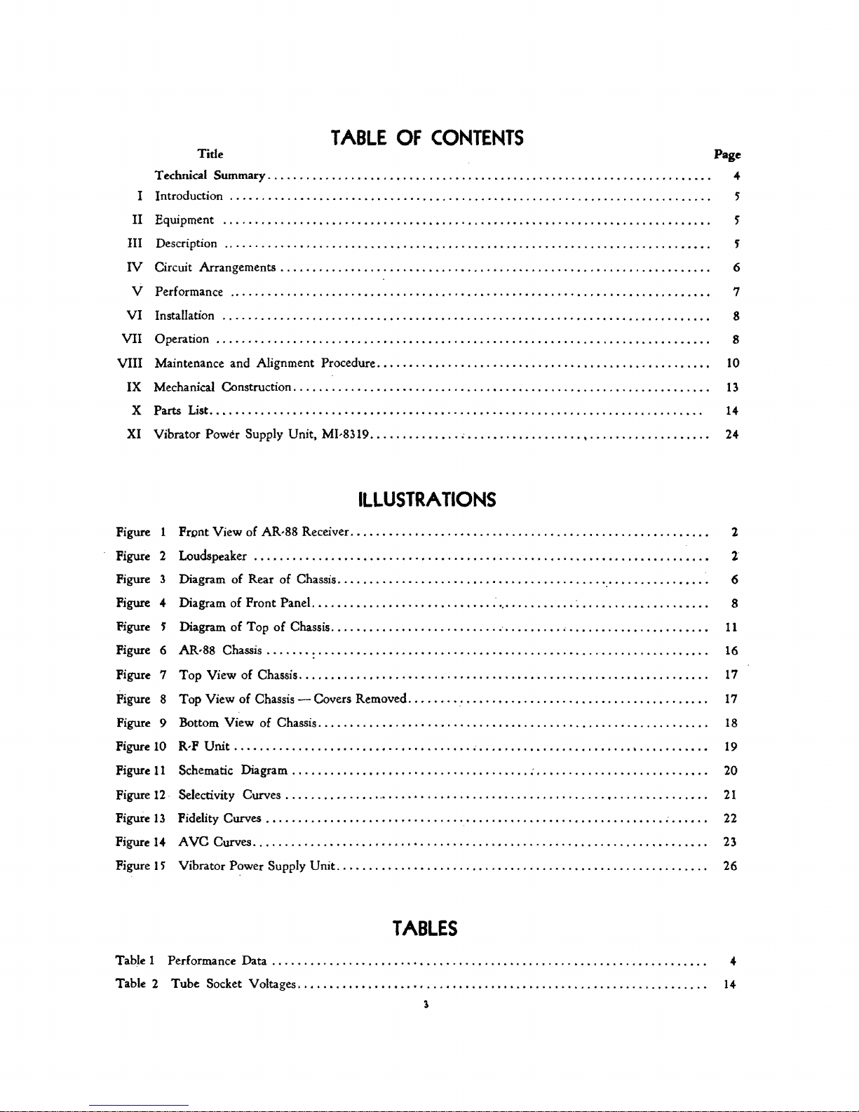
Title Page
TABLE
Summary..................
. . . . . . . . . . . . . . . . . . . . . . . . . . . . . . . . . . . . . . . . . . . . . . . . . . . . . . . . . . . . . . . . . . . . . . . . 5
............................................................................
. . . . . . . . . . . . . . . . . . . . . . . . . . . . . . . . . . . . . . . . . . . . . . . . . . . . . . . . . . . . . . . . . . . . . . . . . 5
OF
CONTENTS
. . • . . . . . . . . . . . . . . . . . . . . . . . . . . . . . . . . . . . . . . . . . . . . . . . . "
W Circuit Arrangements . . . . . . . . . . . . . . . . . . . . . . . . . . . . . . . . . . . . . . . . . . . . . . . . . . . . . . . . . . . . . . . . . . . 6
5'
V Performance
VI
Installation.......................
VII
Operation................................................
VIII
Maintenance and Alignment
IX Mechanical
X Parts
XI Vibrator Power Supply Unit,
Figure
Figure 2
Figure
Figure 4
Figure 5
Figure
Figure
Figure
Figure
Figure
List.............................................................................
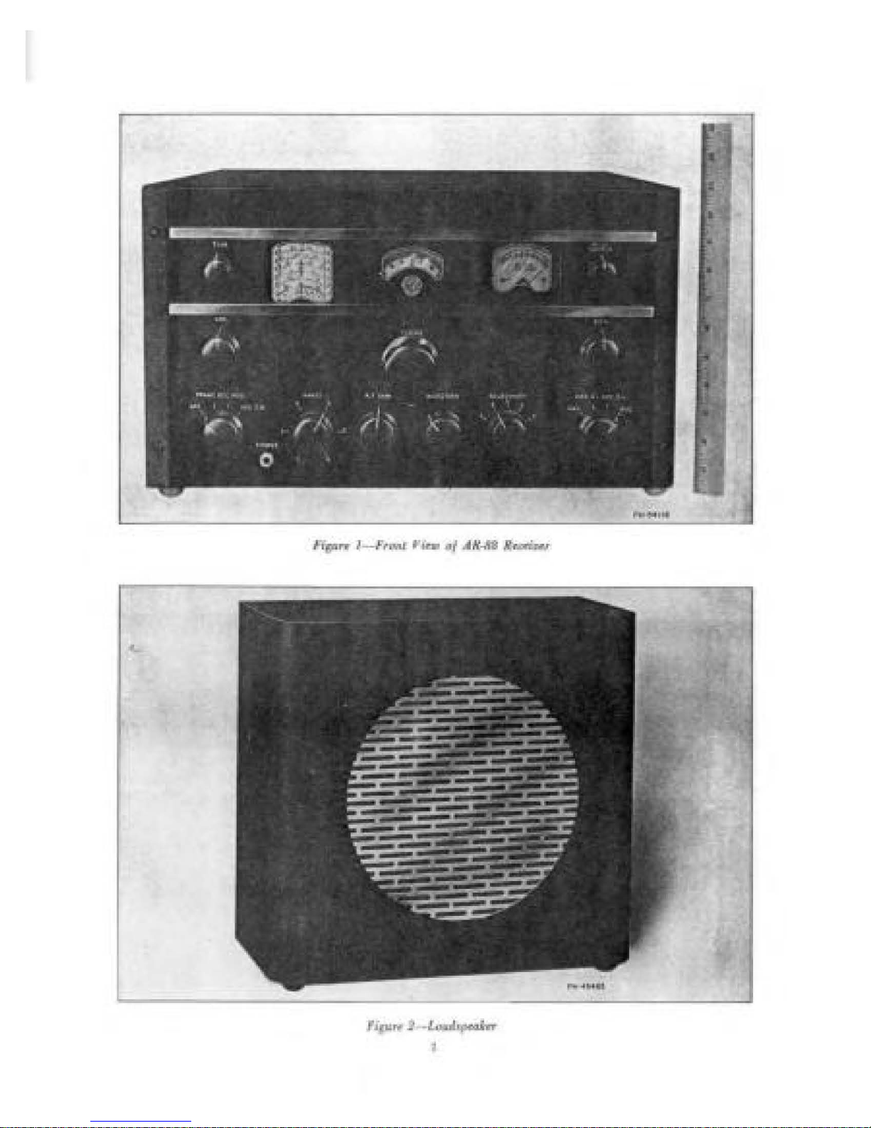
FrDnt View of AR-88 Receiver. . . . . . . . . . . . . . . . . • • . . . . . . . . . . . . . . . . . . . . . . . . . . . . . . . . . . . . . 2
Loudspeaker
3
Diagram of Rear of Chassis
Diagram of Front
Diagram of Top
AR,88
6
Top
7
Top View of Chassis - Covers Removed. . . . . . .
8
Bottom View of Chassis. . . . . . . . . . . . . . . . . . . . . . . . . . . . . . . . . . . . . . . . . . . . . . . . . . . . . . . . . . . . .
9
R,FUnit
10
...........................................................................
Procedure....................................................
Construction.................................................................
MI-8319......................................................
......................................................•...............•
Panel
..........................•.
of
Chassis
Chassis.....................................................................
View of
Chassis................................................................
...........................................................................
. . . . . . . . . . . . . . . . . . . . . . . . . . . . . . . . . . . . . . . . . . . . . . . . . . . . . 8
. . . . . . . . . . . . . . . . . . . . . . . . . . . . . 8
ILLUSTRATIONS
.........................................
..
,.
'" " ............................
..
. . • . . • . . . . . . . . . . . . . . . . . . . . . . . . . . . . . . . .
: '.'
..........
'.'
..............
'.
. . . . . . . . . . . . . . . • . . . . 8
,... . ........
.........•
7
10
13
14
24
2'
'.
6
11
16
17
17
18
19
Figure
11
Schematic Diagram
Figure 12·
Figure
Figure
Figure
Table 1 Performance Data . . . . . . . . . . . . . . . . . . . . . . . • . . . . . . . . . . . . . . . . . . . . . . . . . . . . . . . . . . . . . . . . . . . . 4
Table 2 Tube Socket Voltages
Selectivity
13
Fidelity Curves
AVe
14
15
Vibrator Power Supply Unit
Curves...................................................................
..............................................................
Curves.......................................................................
............•........................
........ , ....•.........
TABLES
...............•..............................
3
,
..
:...........................
... . ...
..
.......... . ..
,
.......
. .
'"
..
; . . . . . .
......
.....
. .
20
21
22
23
26
14
GENERAL
PURPOSE
COMMUNICATIONS
RECEIVER
MODEL
AR-88
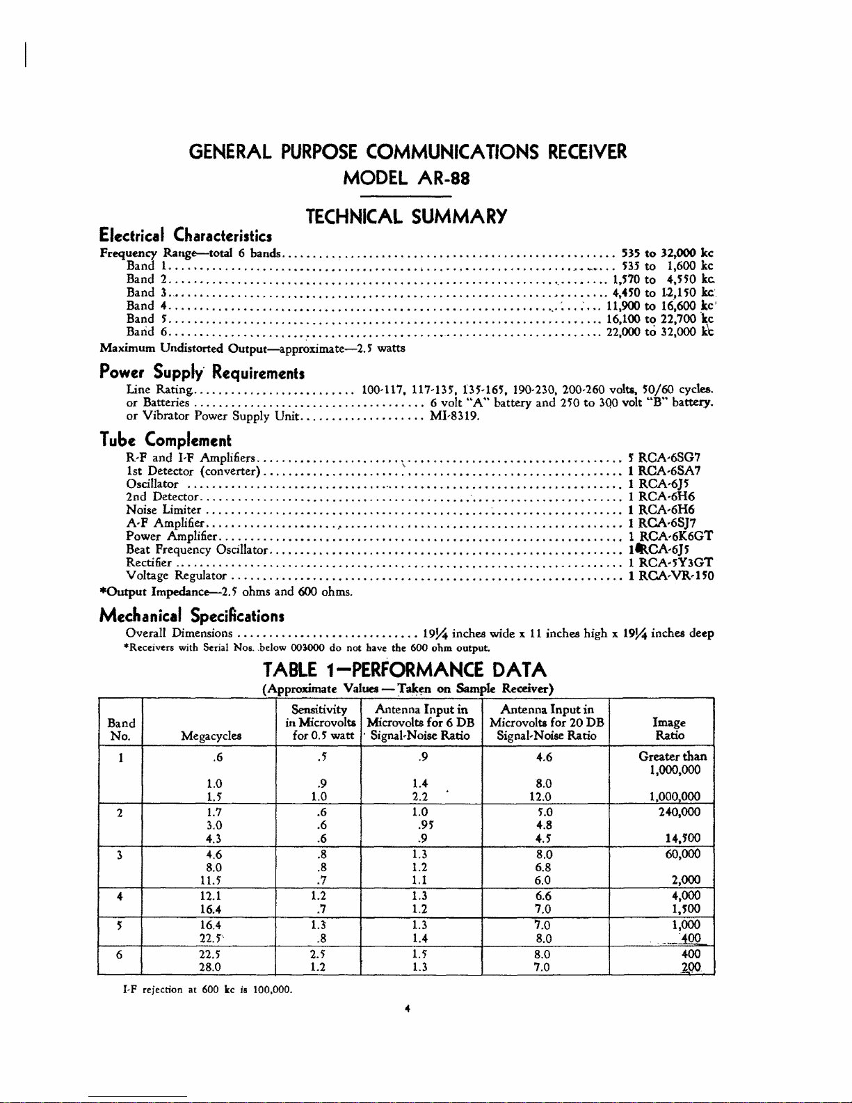
TECHNICAL
SUMMARY
Electrical
Characteristics
Frequency Range--total 6 bands
......... , ............
,
......... , ....................
535
to
32,000
lee
Band 1
....................•••..••....•..•..••.
,
......•.....•........••
~.
"'~
...
535
to
1,600
kc
Band 2
......................•..••..•.............•................•.
,
.•.•....
1,570
to
4,5;0
ke.
Band 3.,
.........•...........•.......••..•..•.••......•.•...........••.......
4,.SO to 12,150
kc',
Band 4
.....................••....•.•..........•....•...........•...
,.:
......
11,900
to
16,600
,kc'
Band 5
.....................................................................
16,100
t~
22,700
~c
Band 6
.......................•.............•.......................•......
" 22,000
to
32,000
KC
Maximum Undistorted
Output-app~ximate-2.
5
watts
Power
Supply'
Requirements
Line
Rating
..........................
100-117, 117-135, 135-165, 190-230, 200-260 volts,
50/60
cycles.
or
Batteries.
'"
..............................
'" 6 volt
"A"
battery and 250
to
3QO
volt
"B"
battery.
or
Vibrator
Power Supply
Unit
...............•....
MI-8319.
Tube
Complement
R-F and I-P Amplifiers
.......••.......•.....•...•..•..•..•.•.•••.••.•.•.....•.••
S'RCA·6SG7
1st Detector (converter)
......•...............
~
........••.............•.....
,
...• 1 RCA·6SA7
Oscillator
...........................•....
'
...................................
" • RCA-6]5
2nd
Detector
................•....•..............
,
.....• ' .•..........•...........
1
RCA·6H6
Noise Limiter
..............•.•...•....................•.•.
'.
. . . . . • • . . • • • . . . . . .
.• 1 RCA·6H6
A·
F Amplifier
...............••..•.
~
• • • . . . . . . . . . . • . . . • • . . • . . . . • . . . . • . . . . • . • . . .
.. • RCA·6S]7
Power
Amplifier. . . . . . . . . . . . . • . . . . . . . . . . . . • . . . . . . . . . . • . . . . . . . . . . . . . . . • . . • . . . . .
.• 1 RCA·6K6GT
Beat Frequency Oscillator
.......•............•.•.•..•.••...•••.....•.•..•.......•
ItllCA·6]5
Rectifier..
. . . . . . . . . . . . . . . . . . . . . . . . . . . . • . . . . . . . . . . . . . . . . . . . . . . . . . . . . . . . . . . . . . .
.. 1 RCA·;Y3GT
V oltage Regulator . . . . . . . . . . . . • . . . . . . . . . . . . . . . . . . . . • . . . . . . . . . . . . . . . . . • • • . . . . . .
.. 1 RCA·
VR·.
50
*Output
Impedance--2.5 ohms and 600 ohms.
Mechanical
SpeciAcations
Overall Dimensions
..........•...........
"
..•.•
1934 inches wide x
11
inches high x 1934 inches deep
*Receivers with Serial Nos, .below
oo~ooo
do
not have the 600
ohm
output.
TABLE
1-PERFORMANCE
DATA
(Approximate Values -
Taken
on
SampJe Receiver)
..
-
Sensitivity Antenna
Input
in
Antenna
Input
in
Band
in Microvolts Microvolts
for 6 DB
Microvolts for 20
DB
Image
No.
Megacycles
for
0.5
watt
. Signal·Noise Ratio
Signal-Noise Ratio
Ratio
1
.6
.5 .9
4.6
Greater
than
1,000.000
1.0 .9 1.4 8.0
1.5
1.0 2.2 12.0 1,000000
2
1.7
.6
1.0
5.0
240,000
3.0
.6 .95 4.8
4.3
.6 .9
4.5 14.100
3
4,6
.8 1.3
8.0
60,000
8.0
.8 1.2 6.8
11.5
.7
1.1
6,0 2,000
4
12.1
1.2 1.3 6.6
4,000
16.4
.7
1.2 7.0
1,;00
5
16.4
1.1 1.3
7.0
1,000
22';'
.8 1.4
8.0
-
..
~OO
6
22.5
2.5 1.5
8.0
400
28.0
1.2
1.3 7.0
200
I·F
rejection at 600 kc is 100,000.
GENERAL
PURPOSE
COMMUNICA
TlONS
RECEIVER
I
INTRODUCTION
In
the design of a high frequency radio receiver,
there are four important qualities for consideration:
1.
Usable sensitivity.
2. Selectivity.
3. Frequency Stability.
4. Reliability.
The
sensitivity of this receiver
is
limited only by
the tube noise originating in the first tube and its
asso-
ciated circuits. A large ·part·
of
this noise
is
due to
"shot" effect and thermal agitation in the first tuned
circuit. A signal, to be readable, must
produce a volt:
a&-e
on the grid,
of
the same or
greate~
ordet: of mag'
I1Lt!Jde
than this inherent noise voltage. Therefore, an
efficient coupling system between the antenna and the
first R,F tube of the receiver
is
of great importance.
This
has been the subject of considerable develop"
ment, and the system used on this receiver gives opti,
mum coupling with antenna or transmission line
im'
pedances
of
200
ohms, over the entire frequency
range of the receiver, except on the broadcast band.
On
the
broa~ast
band, a low frequency primary
is
used, resonating well below the band with a 200 mmf
antenna.
The
second quality of a receiver, selectivity, is
nec'
essarily a compromise with fidelity of the reproduced
signal. This receiver
is
designed
to
have
five
degrees
of selectivity, three of which include a crystal filter.'
1'0 secure good frequency stability, rugged con'
struction of parts and wiring in the high frequency
heterodyne oscillator circuit has been included in
the
design. This, together with voltage stabili2;ation of
the oscillator plate supply, temperature compensation,
and proper oscillator excitation, provides a high
de'
gree of stability.
Reliability depends
to
a large extent on the quality
of
material and workmanship. Throughout the AR,SS
Receiver the best material obtainable is used for each
particular purpose and
all
workmanship is of the best.
The
following instructions should be studied before
the installation or operation
of
this equipment is
at'
tempted, in order
that
optimum performance may
be
obtained.
11
EQUIPMENT
The
equipment furnished consists of the Receiver
Chassis Assembly, including control panel and
tubes and cabinet for complete enclosure for table
mounting.
Additios:al equipment required includes headphones
or
loudspeakers, an antenna system, and an
AC
sourCe
of power, batteries,
or
Vibrator Power Supply
Unit
MI'8319.
III
DESCRIPTION
This receiver covers short wave, standard broad,
cast, and
r;:,w
service; its principal use
is
for short
wave. communications.
It
is designed
to
withstand
severe climatic and line voltage variations without
ap'
preciable impairment
of
performance.
Its features include: .
Mechanical Band
Spread with Single Control for
ease of tuning a previously logged station.
Automatic Noise Limiter which automatically
limits interference
to
a percentage of modula'
tion determined
by
the Noise Limiter Control.
Noise Limiter Control for setting Noise Limiter
to
operate at any desired percent modulation.
Noise Limiter
Switch for switching Noise Lim-
iter on
or
off.
Continuously variable
High
Prequency
Tone
Control.
$
nntenna
trimmer for circuit alignment.
Crystal filter for ultra'sharp selectivity when
re-
quired.
Tuning meter for indicating relative strength
of
incoming signals.
Exceptionally good oscillator stability through
normal variations in line voltage.
Pour'gang Condenser giving high image ratio
on
all
bands.
Twelve Tuned
I,P Circuits giving a very high
degrelllOf selectivity.
Temperature compensated oscillator circuits on
all bands.
Ceramic Insulation throughout on gang
condenser, sockets, range switch, and selectivity
switch.
Tuning Lock for service under extreme condi,
tions of vibration.
IV
CIRCUIT
The
circuit
is
consists of two stages of
tector,
amplification, second detector, noise limiter, second
heterodyne oscillator;
power
designed
ohm
The
denser adjustable from
first heterodyne oscillator; three stages of I,P
stage and power supply system.
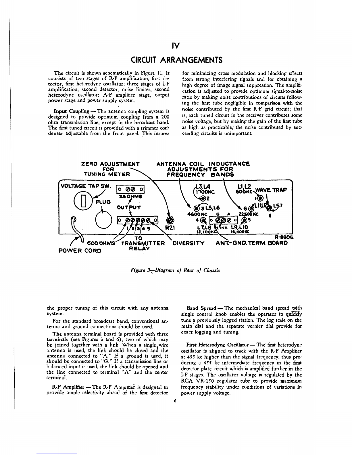
Input Coupling -
transmission line. ,except in the broadcast band.
nrst tuned circuit
VOLTAGE
shown schematically in Figure
to
provide ,optimum coupling from a 200
R'F
amplification, first de'
A,
P amplifier stage. output
The
antenna coupling. system is
is
provided with a trimmer con'
the
front panel. This insures
ZERO AD.JUSTMENT
TAP
SW. 1
PLUG
~U
FOR
METER
00
0
2.S/MS
0 T T 6
01
TUNING
friVO
\J::!)
ARRANGEMENTS
1l.
ANTENNA
It
for minimizing cross modulation and blocking effects
from strong iryterfering signals and for obtaining a
high degree
cation
ratio by making noise contributions
ing the first tube negligible in comparison with the
noise contributed
is, each tuned circuit in the receiver contributes some
noise voltage.
as
high
ceeding circuits is unimportant.
COIL
ADJUSTMENTS
FREQUENCY
of
image signal suppression.
is
adjusted
as
to
provide optimum signal.ta-noise
by
the first
but
by making the gain
practicable, the noise contributed
INDUCTANCE
FO~
R'P
BANDS
of
grid circuit; that
Jc!o~-{~V!.
tt!) l
~11~S7
The
amplifi'
circuits follow'
of
the first tube
by
suc'
TRAP
~'~()-~~Tlo~~R~--~~~~--'~
~!
6000HMS
POWER
the
proper tuning of this circuit with any antenna
system.
Por
the standard broadcast band, conventional an-
tenna
and
The
antenna terminal board
terminals (see Pigures 3 and
be
joined together with a link.
antenna
antenna
should be connected
balanced input
the
line connected to terminal
terminal.
R.F
Amplifier -
provide ample selectivity ahead of the first detector
CORD
ground connections should be used.
is
used. the link should be dosed and the
connected
to
"A."
to
is
"G,"
used, the link should be opened and
The
R,P
TRANSWTTER
RELAY
Figure
3,Diagram
is
provided with three
6),
two of which may
When
a single, wire
If
a ground
If
a transmission line
"A"
AmpI1fier is designed
is
used,
and the center
it
or
'
te
DIVERSITY.
of
Rear
of
Band Spread single control knob enables the operator to
tune a previously logged station.
main'dial and the separate vernier dial provide for
exact logging and tuning.
First Heterodyne
oscillator
at
4H
kc
ducing a
detector plate circuit which
I,P stages.
ReA
VR·150
frequency stability under conditions of variations
power supply voltage.
6
ANT.-GND. TERM.
Chassu
The
mechanical band spread with
Oscillator -
is
aligned
higher
45'5
The
to
track with the R,P Amplifier
than
the signal frequency, thus pro-
kc
intermediate frequency in the first
oscillator voltage
regulator tube
The
The
is
amplified further
to
R-e80E
BOARD
qwCHy
Ipg
scale
on
first heterodyne
in
is
regulated by the
provide maximum
the
the
in
Intermediate Frequency Crystal Filter -
The
first
detector plate circuit is tuned
to
the intermediate fre,
quency and a balanced link circuit
is
used
to
couple
the
first detector plate and first I,P grid circuits. A
4H
kc crystal
is
connected
in,
one
arm
of
the
link cir'
cuit and a neutralizing capacitor is connected in the
other.
The
impedances of the coils in the link circuit
. are designed so
that
the crystal selectivity character-
istic
is
not impractically sharp. The band width
at
two
times resonant
input may be adjusted to 400 cycles,
1.100 cycles,
or
3,000 .cycles. Por this adjustment see
"Operation." .
Intermediate
Frequency
Amplifi,1!r
- Three stages
of
I·P amplification are used; RCA,6SG7 tubes are
used in all stages and an
RCA6H6
tube is used
fof
AVC
and second detector. The first I,P Transformer
has its primary and secondary tuned, and
is
coupled
through the crystal filter link. The second and third
I·P
Transformers are
compOSE;d
of four tuned circuits
each.
These circuits are varied in coupling by
the
selectivity
Switch.
The
fourth I·P Transformer has
t
two
tuned circuits.
•
The
third I·P stage
is
not connected
to
the
AVC
.~
nor
to
the manual volume control so
that
a good
AVC
. 'characteristic with little overload distortion is ob-
tained. This also permits the
CW
oscillator
to
be
coupled to
the
grid circuit of this stage, giving a com'
paratively highde,tector excitation voltage with small
electrical coupling
to
the oscillator circuit.
Second
H~erodyne
Oscillator -
The
second het·
erodyne
(CW)
oscillator is a triode
RCA-6];
tube
which is electrostatically coupled to the finall-P stage.
.(\ pant;l control
is
provided by means'of which
the
frequency of' the heterodyne oscillator and resultant
audio
beat n&e may be varied.
Par:t1cular
care has been taken in the design
of
the
circuit constants to minimize oscillator harmonics.
Automatic Volume
Control-
The
AVC
voltage is
obtained from the second detector, an
RCA·6H6
tube.
A variable delay is obtained depending on the setting
of
the R,P gain control.
.'
The
second heterodyne
(CW)
oscillator excitation
voltage
is
just lower than the A
VC
diode bias voltage
so that it does not decrease the sensitivity
of
th(
receiver.
Manual Volume
Control-
Two
manual volum(
controls are provided; an audio gain control which
i~
employed when the
AVC
is
in use, to obtain the de-
sired output level, and
an
R·P gain control.
Noise Limiter -
The
noise limiter circuit utilizes
an RCA·6H6 tube and limits the noise interference te,
100% modulation and
to
continuously lower percent·
ages
down to any modulation whatsoever, determined
by the setting of the noise
Iimiter control.
A noise limiter switch in conjunction with A
VC
provides for
use
of
the noise limiter on
CWor
on
modulated reception when interference
is
preserit.
*Output Tube -
The
RCA
6K6GT output tube
is
resistance coupled from the A·P amplifier, an
RCA·
6S}7
tube, and operates into an output transformer
which has taps for matching into a
2.5'
or 600 ohm
load. Terminals are provided on the rear apron for
each of these load impedances.
The
output from the
2.5'
ohm tap
is
fed directly to the
2.5'
ohm output
ter'
minal, while the output from the 600 ohm tap
is
fed
to
the 600 ohm output terminal through a
two'
position
jack mounted on the panel.
With
the phone plug
in'
serted into the jack in the first position, the phones
are
in
parallel with the 600 ohm output and
both
are
on.
With
the plug pushed in to the second position,
the
600 ohm output is cut off from
the
rear terminals.
Power Pack -
The
power pack mounted on
the
receiver chassis consists of a power transformer, rec'
tifier tube RCA·5'Y3GT, and filter. A tap switch is
provided on the rear apron for changing the power
transformer voltage tap. (See
Pigures 3 and 6.)
The
voltage for which the switch
is
set may be read di,
rectly on the switch.
The
instrument may also be
operated from 6V.
"A"
and 250 to
300
V.
"B"
bat'
teries, or Vibrator Power Supply
Unit
MI,8319.
Shielding -
Interstage shielding is provided to in-
sure stability under
all
operating conditions
and
to
minimize oscillator radiation. Complete external
shielding prevents coupling to any portion
of
the
cir·
cuit except through the antenna circuit,
V
PERFORMANCE
The
performance data under technical summary
and the data for the various curves, are approximate
values taken on a sample receiver. Variations in these
values are
to
be
expected because
of
practical manu'
facturing
toleran~es.
The
data were taken with an
artificial antenna of
200 mmf. capacity for band 1
and
200 ohms resistance for bands 2 to 6 inclusive.
The output was measured across a resistance
of
2.5'
ohms connected in place of the speaker voice coil.
The selectivity switch was placed in position
2.
•
On
AR·SS receivers with serial numbers below 003000,
the
600 ohm outPUt
is
not provided.
The
speaker terminals on the
rear are for 2.5 ohm load, and a
20
ohm tap
is
provided for phones. With the head phone plug inserted into the jack in
the
first poJition, the phones are
in
parallel with the
2.5
ohm speaker terminals and both are on. With the plug pushed in to the
lecon.d position, the speaker terminals
at~
cut off and the phones are connected to the
20
ohm winding. This winding
8'ive~
luJliclent
output
for phones up
to
2000 ohms impedance.
7
INSTALLA
Power Supply -
tegral with the receiver. Determine line voltage and
frequency and check with the rating
The
power transformer primary may
anyone
for
switch. This switch is located in the rear apron of the
receiver. and the voltage for which
read directly on the switch.
For Battery
nections see Schematic Diagram Figure
necessary to remove the plug from the socket on
rear
of
proper terminals
gram. A battery cable terminating' in an octal male
plug
supply
receiver directly from a 6 volt storage battery. For
information on this power unit
to
tive sockets.
terminals
the receiver, and connect the batteries
is
necessary for this purpose. A vibrator power
MI,8319
Tubes -
see
Antenna
Inspect the chassis before applying power
that
all tubes are firmly seated in their respec'
- The input impedance
is
The
power supply circuit
of
be
of
five
voltage
or
other Supply Operation - For con'
as indicated by the schematic dia'
is
available which will operate the
designed to match a 200 ohm transmis'
r3:nges
see
by means
it
is
Section XI.
at
is
the receiver.
connected
of
a tap
set may be
11.
It
is
only
to
the antenna
in'
the
the
VI
TION
sion line except on the
frequency primary
For general use it
wire antenna between
Speaker Terminals for connection
speaker are indicated in Figures
transformer is designed to match a speaker having
2.25 ohms impedance.
Headphones - A jack
the front panel for plugging in a pair of headphones.
There are two positions
1.
Half
way
and phones.
2.
Fully. in-=-for phone receptiori only.
See
Tube."
table
the panel mounting screws and remove the front
panel and chassis complete from the cabinet.
mount on rack by means of the slots
the panel.
"CIRCUIT
Mounting -
or
mounted on a rack.
The
VII
broadcast band where a low
is
used.
is
recommended that a straight
25
and m feet long be used.
at
6.
of
The
the
the
3 and
is
provided on
of
the plug.
in-for
reception on both speaker
ARRANGEMENT"
instrument may be placed on a
ror
rack mounting loosen
a loud,
output
left
of
"Output
Then
sideS
of
OPERATION
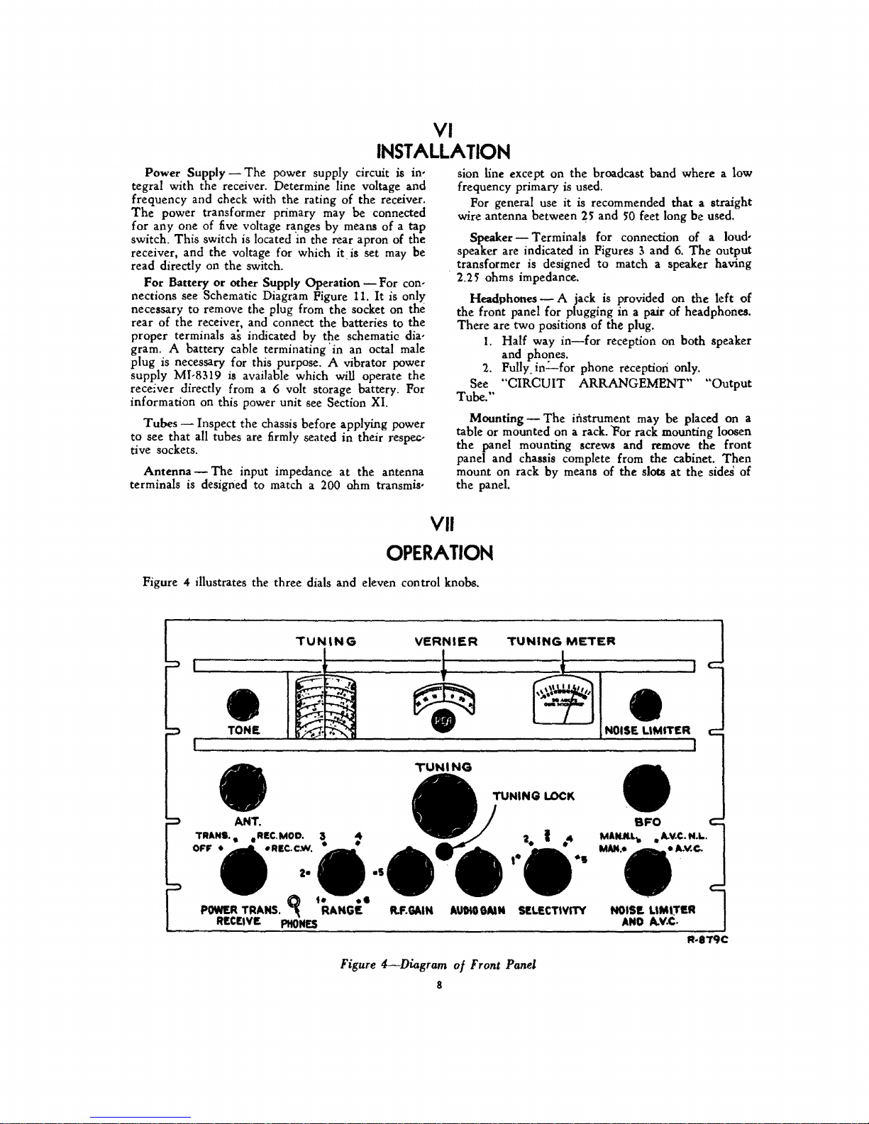
Figure 4 illustrates the three dials and eleven con trol knobs.
TUN'NG
I
TONE.
•
I
ANT.
TRANS.. .REe.MOD. 3
OFF
•
;;.-..-
,-'''''';
.;...
.......
~
;r;;~,
_REC-CloY.
ttII
..
~
1 •
•
-., .
.!
;......f!;"
~
•
;R
~
Figure
VERNIER
~
•
TUNING
M.GAIN
4-Diagram
8
I
AUDIO
of
Front Panel
GAtM
TUNING
METER
I
-*-
\ \ \1
'"
\..-.::.
--~;
SELECTIYITY
I
J
NOISE
LlMIT£R
•
SFO
M1NJlU.... • II..Y.e..
MAN..
NOIS!. LlMl.TI!.R
AND
A.V.C.
I
I
N.L.
.1I..v.c.
R-8T9C
 Loading...