

Page 1
INDOOR
Five Year Limited Warranty
ANT500
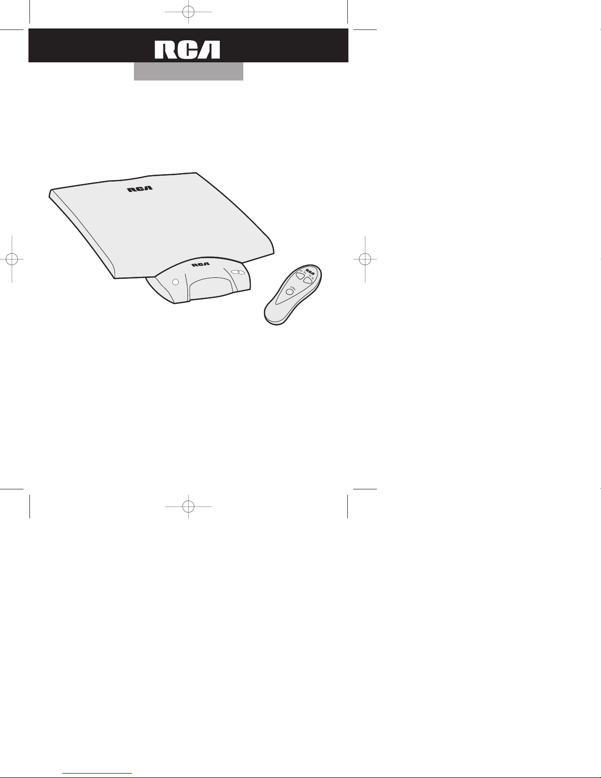
Thank you for choosing the RCA Low Profile Antenna with
Amplifier and Narrow Band Tuning. This antenna combines high
performance with unique design to provide excellent TV reception.
Before attempting to use your antenna, please remove all parts
from the box and read the instructions carefully.
Low Prof ile
™
TV Antenna
ANT500 Manual 6/10/99 1:10 PM Page 1
Page 2
ANT500 Manual 6/10/99 1:07 PM Page 2
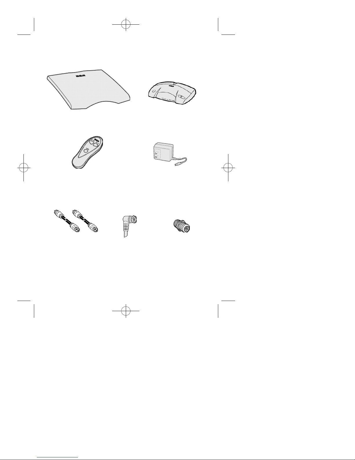
Contents
Antenna Element Amplifier/Tuner
Coaxial Cables
2
Remote Control
(2) 6ft.
Short Coaxial Cable
with 90º Connector
12Vdc, 500mA
Power Adapter
Inline “F”
Connector Coupler
2 “AAA” Batteries (Included)
Page 3
ANT500 Manual 6/10/99 1:07 PM Page 3
CAUTION
RISK OF ELECTRIC SHOCK
DO NOT OPEN
CAUTION: TO REDUCE THE RISK OF ELECTRIC SHOCK DO NOT REMOVE COVER OR BACK. NO
USER SERVICEABLE PARTS INSIDE. REFER SERVICING TO QUALIFIED SERVICE PERSONNEL.
Important Safeguards
• Read and follow the instructions before operating.
• Retain the instructions for future use.
• Follow all warnings on the adapter and instructions.
Water and Moisture
Do not use this antenna near water. Keep away from a bathtub, sink, wet
basement or swimming pool and other wet places.
Power Source
The wall adapter for this antenna should be operated only from a standard
120 V, 60 Hz wall outlet. If you are not sure of the type of power supply to
your home, contact your local power company.
Servicing
Do not attempt to service this antenna yourself as opening or removing covers may expose you to dangerous voltage or other hazards and voids your
warranty. Refer servicing to qualified service personnel.
Cleaning
Unplug the antenna from the wall outlet before cleaning. Use a lint free
cloth for cleaning the outside of the unit only. Do not use aerosol cleaners.
Important Information
Your antenna’s AC adapter operates on 120 volts AC, 60 Hz.
CAUTION:
• To reduce the risk of electric shock, do not remove the cover or back of the
AC adapter or antenna. There are no user serviceable parts inside.
• If you spill liquid on the AC adapter or antenna, disconnect the AC
adapter’s power cord from the AC outlet to prevent possible fire or shock
hazard and consult authorized service personnel.
To prevent damage to internal parts, do not expose the antenna to moisture.
•
• Maintain electrical safety. Powerline-operated equipment or accessories
connected to this unit should bear the UL listing mark or CSA certification
mark on the accessories themselves and should not have been modified so
as to defeat the safety features. This will help avoid any potential hazard
from electrical shock or fire.
If in doubt, contact qualified service personnel.
!
3
Page 4
ANT500 Manual 6/10/99 1:07 PM Page 4
Installation
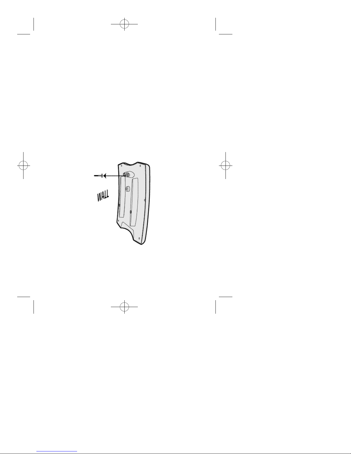
Wall Mounting and Operating Instructions
The antenna is designed to be mounted on a wall in a discreet, out of sight
location. For example, it may be hidden behind furniture. The antenna will
perform better if located as high as possible, and away from power outlets
and wires inside the wall. Do not place the Antenna Element
directly beneath the TV or other electronic equipment.
Prior to selecting a permanent location for the antenna, proceed with
hooking the antenna up to your TV or VCR and experiment by moving the
element to get the best picture possible. See “Installation” page 5.
Once the final hanging location is selected, mount the antenna by using the
V hanger on the back of the antenna element. The antenna will hang from a
hook or screw inserted into the wall.
There should be no need to reposition the antenna element once installed.
4
Page 5

ANT500 Manual 6/10/99 1:07 PM Page 5
Installation
For Installation of Amplifier/Tuner
Separated from Antenna Element
1. Locate the Antenna Element.
Connect the right angle end of
the Short Coaxial Cable to the
connector on the bottom of the
Antenna Element.
2. Locate the Inline “F” Connector
Coupler. Connect one end of the
6ft. Coaxial Cable to the free end
of the Short Coaxial Cable with
the Coupler.
3. Locate the Amplifier/Tuner. Attach
the other end of the 6ft. Coaxial Cable
to the “IN (Antenna)” connector on the
back of the Amplifier/Tuner.
4. Connect one end of
the second 6ft.
Coaxial Cable to
the “OUT (to TV)”
connector on the back
of the Amplifier/Tuner,
and connect the other
end to the“Antenna”
connector on the back
of your TV or VCR.
5. The Amplifier/Tuner
should be positioned
in line-of-sight of the
Remote Control.
Antenna Element
Short Coaxial Cable
Inline “F”Connector Coupler
6ft. Coaxial Cable
Back of
Television
6ft. Coaxial Cable
Amplifier/Tuner
5
Page 6

ANT500 Manual 6/10/99 1:07 PM Page 6
For Installation of Combined Element and Amplifier/Tuner
The Antenna Element and Amplifier/Tuner can be used as a combined unit
for positioning on flat surfaces like the top of a TV cabinet. To avoid blocking
the broadcast signal, do not place the unit beneath the TV or any other
electronic component.
1. Locate the Antenna Element. Connect the right
angle end of the Short Coaxial Cable to the
connector on the bottom of the Antenna Element.
2. Locate the Amplifier/Tuner. Attach the other end
of the cable to the “IN (Antenna)” on the back
of it. Place the combined Antenna Element and
Amplifier/Tuner in a spot visible to the remote
control (ideally on top of the TV).
3. Connect one end of the second 6ft. Coaxial Cable to the “OUT (to
TV)” connector on the back of the Amplifier/Tuner Unit, and connect
the other end to the “Antenna” connector on the back of your TV or
VCR. Cables should be routed under the Antenna Element and out the
back to the “Antenna” of your video equipment.
4. The Amplifier/Tuner should be positioned in line-of-sight of the
Remote Control.
Power
1. Connect the Power Adapter to the Amplifier/Tuner by inserting the plug
into the “DC Input” on the back of the unit.
2. Plug the Power Adapter into a 110/120 Volt, 60 Hz. Outlet.
3. Turn the Antenna ON by
pressing the POWER button on
the Amplifier/Tuner or by aiming
the remote at the Amplifier/Tuner
and pressing the POWER button.
A red indicator light on the
Amplifier/Tuner will show power
is ON.
6
500mA
12vDC
OUT
(To TV)
(Antenna)
IN
Page 7

ANT500 Manual 6/10/99 1:07 PM Page 7
Tuning and Using the Antenna
Insert 2 “AAA” batteries in the Remote Control.
Turn on Amplifier/Tuner using either the POWER button on the Remote
Control or the Amplifier/Tuner.
Tune the antenna by using the arrow keys on
the Remote or Amplifier/Tuner. Toggle up or
down through the tuning positions until you get
the best picture for the channel you are
watching. A red indicator light will show which
of the five tuning positions is selected.
Channel
Down
Remote Control
Using an RCA Universal Remote Control
If you have an RCA Universal Remote Control, the Amplifier/Tuner can be
operated by using VCR code 020. If the remote has an AUX key, the code
can be programmed under that key by following the instructions that came
with the remote control. The following VCR keys can be used to operate the
antenna as shown in the following chart:
U. Remote Operates
Key Amp./Tuner
STOP Power ON/OFF
F.FORWARD Channel Up (CHAN UP)
REWIND Channel Down (CHAN DN)
Power
Channel
Down
Channel
Up
Power
Channel
Up
Amplifier/Tuner
7
Page 8

ANT500 Manual 6/10/99 1:07 PM Page 8
ALSO AVAILABLE: Cable TV & Satellite Surge Suppressors
SCTV90
FEATURES:
•6 Outlets
•640 joules
•Cable/TV Satellite Protection
•Phone/Modem/Fax Line Protection
•Flat Profile Plug
•Diagnostic Indicator Lights
•Noise Reduction
•Accommodates AC Adapter
•$25,000 Equipment Guarantee
•Lifetime Limited Warranty
SCTV160
FEATURES:
•8 Outlets
•940 joules
•Cable/TV Satellite Protection
•Phone/Modem/Fax Line Protection
•Audible Alarm
•Diagnostic Indicator Lights
•Noise Reduction
•Accommodates 4 Large AC Adapters
•$50,000 Equipment Guarantee
•Lifetime Limited Warranty
$
3 4
$
4 9
O N LY
O N LY
9 5
9 5
*
*
TO ORDER CALL 1-800-338-0376
(VISA, Mastercard, Discover Accepted)
8
*Shipping/Handling & Sales Tax
will be added to all ord e r s .
Page 9

ANT500 Manual 6/10/99 1:07 PM Page 9
9
Page 10

ANT500 Manual 6/10/99 1:07 PM Page 10
ANT500 Purchase Registration Card
Please complete and return this Purchase Registration Card right away. This
information will help us get to know and service our customers better.
1.❏ Mr. ❏ Mrs. ❏ Ms. Name: ______________________________
Address: ________________________________________________
_______________________________________________________
3.Date of Purchase/Receipt as Gift:________ 4. Price: $__________
4.Age of Purchaser/Gift Recipient:
❏ 16-25 ❏ 26-35 ❏ 36-45 ❏ 46-55 ❏ 56+
5.How will this antenna primarily be used?
A .
With T V o n l y ❏
❏
6.How did you become aware of this antenna?
A.
Advertisement ❏
❏
❏
D.
Received as a Gift ❏
7.What other brands did you consider buying?
❏
B.
Jasco ❏
E.
Gemini ❏
❏
8.What factors most influenced this purchase?
❏
A.
Brand ❏
❏
D.
Price ❏
G.
Other
❏
9.Why did you purchase this antenna?
❏ A. Receiving off-air programmingwith a cable,
satelliteorDBS System
B.
Improve Reception of Local Stations
❏
❏
C.
Other_________________________________________________
B.
DBS ❏
B.
Salesperson ❏
E.
Friend or Relative ❏
C.
Terk ❏
F.
Recoton ❏
B.
Features ❏
E.
Received as a Gift ❏
C.
H D T V
C.
Store Display
F.
Other ________
❏
A.
Magnavox
D.
Zenith
G.
Other ________
C.
Recommendation
F.
Appearance
What suggestions do you have to improve this product?
_______________________________________________________
_______________________________________________________
Thank you for filling out this card. This information will help us better serve you and others who
purchase RCAProducts. We will not share your information with any other companies.
10
Page 11

ANT500 Manual 6/10/99 1:07 PM Page 11
Five Year Warranty
Thomson Consumer Electronics, Inc. warrants that for 5 years from date of purchase this product will be free from defects in material and workmanship. If the
item is defective within that period, return it at your expense to the dealer from
whom it was purchased together with proof of purchase for replacement. This
warranty excludes defects or damage due to misuse, abuse, or neglect.
THE FOREGOING WARRANTYIS IN LIEU OF ALLOTHER WARRANTIES,
EXPRESS OR IMPLIED, INCLUDING BUT NOT LIMITED TO THE IMPLIED
WARRANTIES OF MERCHANTABILITYAND FITNESS FOR APARTICULAR
PURPOSE. IN NO EVENT SHALLTHOMSON CONSUMER ELECTRONICS,
INC. BE LIABLE FOR SPECIAL, INDIRECT, INCIDENTAL, OR CONSEQUENTIAL DAMAGES, WHETHER IN CONTRACT, TORT, OR NEGLIGENCE.
Some states do not allow limitations on how long an implied warranty lasts or
permit the exclusion or limitation of incidental or consequential damages, so the
above limitations or exclusions may not apply to you.
This warranty gives you specific legal rights, and you may also have other
rights which vary from state to state.
For purchases in Canada, refer to the Canadian warranty.
©
1999 Thomson Consumer Electronics, Inc.
Trademark(s)®Registered
Made in China
1110
 Loading...