

Page 1
ANT3038XR
Outdoor Antenna
User’s Guide
Para obtener instrucciones en español,
consulte la página 9.
Assembling the ANT3038XR
BEFORE YOU START!!!
Please read the IMPORTANT SAFETY INFORMATION sheet included in this
package.
Step 1: Unpack
Remove all three sections of the antenna and the hardware bag from package.
Make sure the following parts are in the package:
• (3) Antenna sections (rear, large/middle, and front booms)
• (1) Boom brace • (2) Refl ector booms
• (1) Hardware bag
The hardware bag contains the following pieces:
(2) U-Bolts (4) 1/4” Flange nuts
(2) Mast clamp inserts (5) End caps
(10) #10 Flange nuts (4) #10 Screws
(8) #10 Washers (1) Matching transformer
English
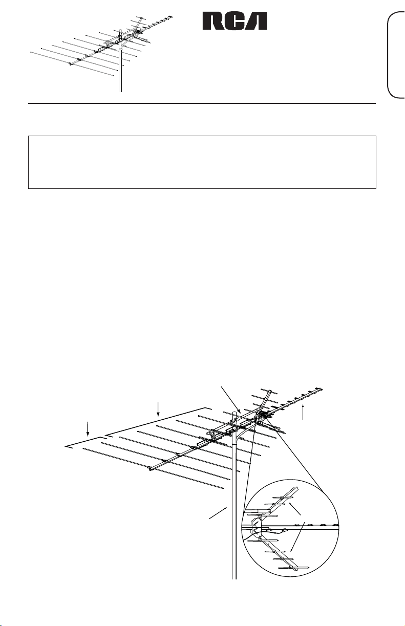
Boom Brace
Large Boom
Rear Boom
Mast
(Not Included)
Fig.1: ANT3038XR fully assembled
(mast not inclued)
Front Boom
Reflector
Booms
Page 2

Step 2: Connect the refl ector booms to the front
(small) boom
Find the two refl ector booms and the front (or small)
boom. The two smaller elements on the refl ector
booms face away from the small main boom.
Fig. 1
IMPORTANT: Unfold the elements on each end of
the refl ector boom so that the front of their locking
tabs face towards each other. The remaining
locking tabs can be unfolded in either direction.
Make sure that all of the elements are perpendicular
to the refl ector boom.
Fig. 2
FRONT
Fig. 2A
Locking Tab
Main Boom
Connect the two refl ector booms to the front boom
using two of the provided #10 nuts and screws.
The refl ector booms should be parallel to the
smaller boom at this point. (See Fig. 1.)
Step 3: Unfold the rest of the antenna
Unfold all the other elements on the antenna until they lock into place ensuring
that they are fl at and parallel to each other. (See Fig. 3.)
Fig. 3
2
Page 3
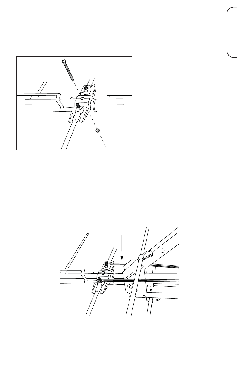
Step 4: Connect the middle (large) section to the
front (small) section
Find the middle (large) section. Locate the end of the middle section that
matches fi gure 4.
Remove the nut and screw in
the center. Slide the narrow
boom of the front (small)
section into the middle (large)
section. Make sure the
phasing lines are on the top
side of the small boom and the
black plastic element holders
are also on this same side.
This is the top of the antenna.
(See fi gure 5.)
Tap lightly with a rubber mallet
on the end of the small boom
aligning the holes for the
screw. (See fi gure 4.)
Re-install the screw and nut;
be sure to tighten securely.
Middle
section
Fig. 4
Front
section
Step 5: Connect the phasing lines
Place the phasing lines from the front section over the studs. Secure them to
the studs with #10 fl ange nuts and washers. Tighten securely.
English
Fig. 5
Phasing Lines
3
Page 4

Step 6: Connect the rear section to the middle
T
(large) section
On the open end of the middle (large)
section, remove the rear nut and screw.
Find the rear section. Slide the narrow
boom of the rear antenna into the middle
(large) section. Tap lightly with a rubber
Rear
section
Screw
Middle
section
mallet on the end of the small boom,
Nut
Fig. 6
aligning the holes for the screw. (See fi gure
6.)
Re-install the screw and nut; be sure to
tighten securely.
Step 7: Connect the phasing lines
On the middle (large) section, near where
Phasing
line
Nut
Washer
Stud
the middle and rear sections come
together, fi nd the posts on the top and
bottom of the last element holder studs.
(See fi gure 7.)
Place the phasing lines from the rear
Fig. 7
section over the studs, one on the top side
and one on the bottom. Then fasten them
to the posts with washers and #10 fl ange
nuts. Tighten securely.
4
Page 5

Step 8: Connect the boom brace
Lay the boom brace on top of the antenna. Make sure the mast clamps (the
brass-colored sections) on the boom brace and antenna are facing the same
direction.
English
Fig. 8
Locate the screw hole in the refl ector boom
and attach the brace with one of the provided
#10 screws and nuts. (See fi gure 8.)
Fig. 9
Nut
Swing the boom brace down towards the
rear. Form a “V” with the metal straps. Use
one of the provided #10 screws and nuts to
attach the “V” to each side of boom. (See
fi gure 9.)
Screw
Step 9: Install the transformer
Find the downlead connection on the bottom of the front section of the
antenna, just beyond the refl ector booms.
Place two washers on each of the studs. Place a #10 nut on top of each stud,
but don’t tighten them yet.
Place the transformer ends between the two washers and tighten the nuts
securely. (See fi gure 10.) Attach the coax downlead to the transformer.
Fig. 10
Transformer
Downlead
connections
5
Page 6

Step 10: Insert end caps
Insert two of the plastic end caps in the ends of the
antenna as shown in fi gure 11.
Insert a third plastic end cap in the exposed end of
the boom brace.
Insert the last two end caps on the ends of the
refl ector booms.
Fig. 11
Use a rubber mallet to gently tap them into the
ends so that they are secure.
Step 11: Mount the antenna to a mast
#10 Nuts
Boom brace
Clamp insert
Main
boom
Clamp
insert
Fig. 12
Fig. 13
Find the two U-bolts, four 1/4” fl ange nuts, and the
two mast clamp inserts.
Place the mast clamp inserts on the inside of the
mast clamps on the antennas as shown in fi gure
12. Then insert the U-bolts into the mast clamps
and mast clamp inserts. Attach the nuts loosely.
Slide the antenna over the mast and lightly tighten
the two mast clamps. (See fi gures 12 and 13.) The
top side of the antenna is the side with the black
plastic pieces on it.
6
Page 7

Step 12: Connect the coax downlead to your TV
or preamplifi er
Fig. 14
Point toward
broadcast
towers
NOTE: Point the small end of the
antenna towards the station(s).
Connect the coax downlead to your
TV.
Rotate the antenna until you receive
the best picture. You will probably
need a helper to view the TV set
while you are rotating the antenna.
Important: Point The Antenna Toward Your Local Broadcast
Towers
Visit www.antennaweb.org to see the locations of your local broadcast
towers. This information is crucial in pointing your antenna correctly.
Step 13: Secure mast clamps and downlead,
ground the antenna
Tighten the two mast clamps securely.
English
Secure the coaxial downlead to the mast (using cable ties or electrical tape) to
prevent it from whipping by the wind.
Ground the antenna and mast per the accompanying grounding instructions.
Antenna Removal
Removal of the antenna should be exactly the reverse of the installation
instructions. Please, for your own safety, follow the instructions for installing
the antenna starting with the last step fi rst.
7
Page 8

12 Month Limited Warranty
Audiovox Electronics Corporation (the “Company”) warrants to the original
retail purchaser of this product that should this product or any part thereof,
under normal use and conditions, be proven defective in material or
workmanship within 12 months from the date of original purchase, such
defect(s) will be repaired or replaced (at the Company’s option) without charge
for parts and repair labor. To obtain repair or replacement within the terms of
this Warranty, the product along with any accessories included in the original
packaging is to be delivered with proof of warranty coverage (e.g. dated bill of
sale), specifi cation of defect(s), transportation prepaid, to the Company at the
address shown below. Do not return this product to the Retailer.
This Warranty is not transferable and does not cover product purchased,
serviced or used outside the United States or Canada. The warranty
does not extend to the elimination of externally generated static or noise.
This Warranty does not apply to costs incurred for installation, removal or
reinstallation of the product, or, if in the Company’s opinion, the product
has been damaged through acts of nature, alteration, improper installation,
mishandling, misuse, neglect, or accident. This warranty does not cover
damage caused by an AC adapter not provided with the product. THE
EXTENT OF THE COMPANY’S LIABILITY UNDER THIS WARRANTY IS
LIMITED TO THE REPAIR OR REPLACEMENT PROVIDED ABOVE AND, IN
NO EVENT, SHALL THE COMPANY’S LIABILITY EXCEED THE PURCHASE
PRICE PAID BY PURCHASER FOR THE PRODUCT. This Warranty is in lieu
of all other express warranties or liabilities. ANY IMPLIED WARRANTIES,
INCLUDING ANY IMPLIED WARRANTY OF MERCHANTABILITY OR FITNESS
FOR A PARTICULAR PURPOSE, SHALL BE LIMITED TO DURATION OF THIS
WARRANTY. ANY ACTION FOR BREACH OF ANY WARRANTY HEREUNDER,
INCLUDING ANY IMPLIED WARRANTY, MUST BE BROUGHT WITHIN A
PERIOD OF 24 MONTHS FROM THE DATE OF ORIGINAL PURCHASE. IN
NO CASE SHALL THE COMPANY BE LIABLE FOR ANY CONSEQUENTIAL
OR INCIDENTAL DAMAGES WHATSOEVER. No person or representative is
authorized to assume for the Company any liability other than expressed herein
in connection with the sale of this product.
Some states/provinces do not allow limitations on how long an implied
warranty lasts or the exclusion or limitation of incidental or consequential
damage so the above limitations or exclusions may not apply to you. This
Warranty gives you specifi c legal rights and you may also have other rights
which vary from state/province to state/province.
U.S.A.: Audiovox Electronics Corporation, 150 Marcus Blvd.,
Hauppauge, NY 11788
CANADA: Audiovox Return Center, c/o Genco, 6685 Kennedy Road,
Unit #3 Door 16, Mississauga Ontario L5T 3A5
8
 Loading...