

Page 1
PHOTOFACT*
Folder
RCA
VICTOR MODELS
9T79
9T89
(Ch.
(Ch.
KCS49,
KCS6O,
A,
A,
9T57,
AT,
T),
AT, T)
9T77,
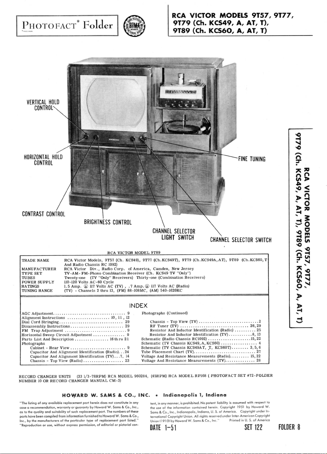
VERTICAL
HOLD
CONTROL-
HORIZONTAL
HOLD
CONTROL
CONTRAST CONTROL
TRADE
NAME
RCA
MANUFACTURER
TYPE
SET
TUBES
Twenty-one
POWER
SUPPLY 110-120
RATINGS
TUNING
RANGE
RCA
TV-AM-
1.5
(TV) - Channels 2 thru
BRIGHTNESS CONTROL
Victor
And
Models,
Radio
Chassis
Victor
Div.,
FM-Phono Combination
(TV
Volts
Amp.
® 117
RCA
9T57 (Ch. KCS49),
RC
1092)
Radio
"Only"
AC-60 Cycle
Volts
AC
13,
CHANNEL SELECTOR
LIGHT
VICTOR
MODEL
9T89
9T77
(CK.KCS49T),
Corp.
of
America,
Receiver
Receivers)
(FM) 88-108MC, (AM) 540-1620KC
Thirty-one (Combination
(TV) , .7
Amp.
Camden,
(Ch.
® 117
KCS49
Volts
New
TV
SWITCH
9T79
Jersey
"Only")
AC
(Radio)
(Ch.KCS49A,
Receivers)
FINE
TUNING
CHANNEL SELECTOR SWITCH
AT), 9T89
(Ch.KCSGO,
T
o
x~>
r»
So;
-o
~S
n
rj
3-
Ul
AGC
Adjustment
Alignment
Dial
Cord Stringing
Disassembly
FM
Trap
Horizontal Sweep
Parts
List
Photographs
Cabinet - Rear
Capacitor
Capacitor
Chassis
RECORD
NUMBER
"The listing
case a recommendation, warranty
as
to the
quality
parts have been
Inc.,
by the
"Reproduction
9
Instructions
29
Instructions
Adjustment
And
- Top
CHANGER
10 OR
of any
and
compiled
manufacturers
or
9
Circuit
Description
View
And
Alignment Identification
And
Alignment Identification
View (Radio)
UNITS
RECORD
HOWARD
available
replacement
suitability
from information furnished
of the
use, without express permission,
10, 11 , 12
29
Adjustment
16
9
(33
CHANGER
or
of
such
particular
9
(Radio)...
23
1/3-78RPM)
part
guaranty
replacement
type
(TV)..
RCA
MANUAL
W.
herein does
by
CM-3)
SAMS & CO., INC. • Indianapolis
not
Howard
W.
part.
The
to
Howard
of
replacement
of
editorial
th
ru
21
24
.7,
14
MODEL 960284,
constitute
Sams & Co.,
numbers
W.
Sams & Co.,
part
or
pictorial
INDEX
in any
Inc.,
of
these
listed."
con-
Photographs
Chassis
RF
Tuner
Resistor
Resistor
Schematic
Schematic
Schematic
Tube
Placement
Voltage
And
Voltage
And
(45RPM)
tent,
in any
the
use of the
Sams & Co., Inc.,
ternational
Union
DATE
(Continued)
- Top
View (TV)
(TV)
26, 29
And
Inductor Identification (Radio)
And
Inductor Identification (TV)
(Radio
Chassis
(TV
Chassis
(TV
Chassis
Chart
Resistance
Resistance
RCA
MODEL RP168
manner,
is
information contained herein. Copyright
Indianapolis,
Copyright Union.
(191
0)
by
Howard
2
RC1092)
KCS49,
A,
KCS49AT,
(TV)
' 27
Measurements
Measurements
1,
Indiana
prohibited.
No
Indiana,
AH
rights
W.
Sams & Co.,
1-51
25
15, 22
KCS60)
T,
PHOTOFACT
patent
U. S. of
reserved
Inc." Printed
8,
4
KCS60T)
3, 5, 6
(Radio)
15, 22
(TV)
28
SET
#72-FOLDER
liability
is
assumed with
1951
America. Copyright under
under Inter-American Copyright
by
in U. S. of
SET
122
13
respect
to
Howard
W.
In-
America
FOLDER
8
Page 2
CO
CO
co
<
I
(J
PAGE
2
Page 3

-L
loooo
JtfLillltimf
A
PHOTOFACT
STANDARD
©Howord
W.
Soms & Co.,
NOTATION
Inc. 1951
SCHEMATIC
DOTTED
MODELS.
USED
IN
MflTS
POINTS
WHEN
ARE NOT
MARKED
USED
DOTTED
IN ALL
X ARE
IN
R
BROKEN.
PAGE
5
PAGE
Page 4
®6AU6
SYNC.
AMP.
-
e®6SN7GT
AGE
6
Page 5
-®~-
•M
S
VEL,
BLK-PED
I
270
-L-
L
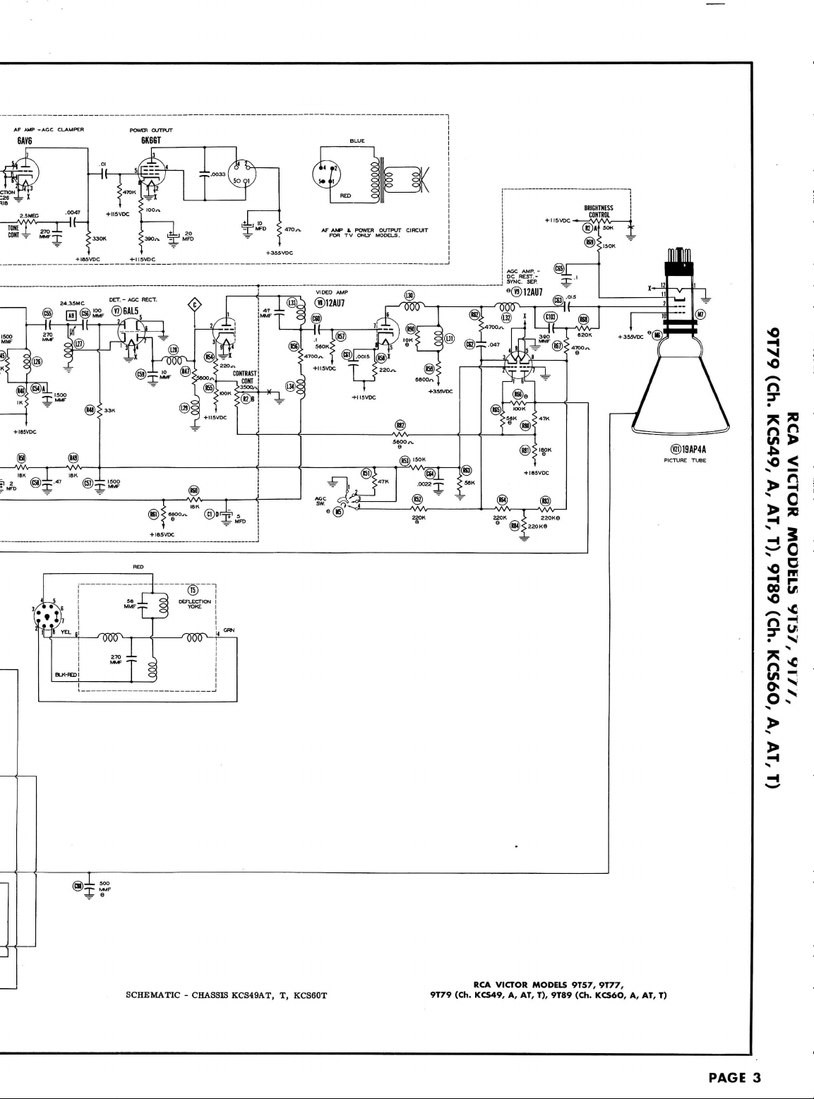
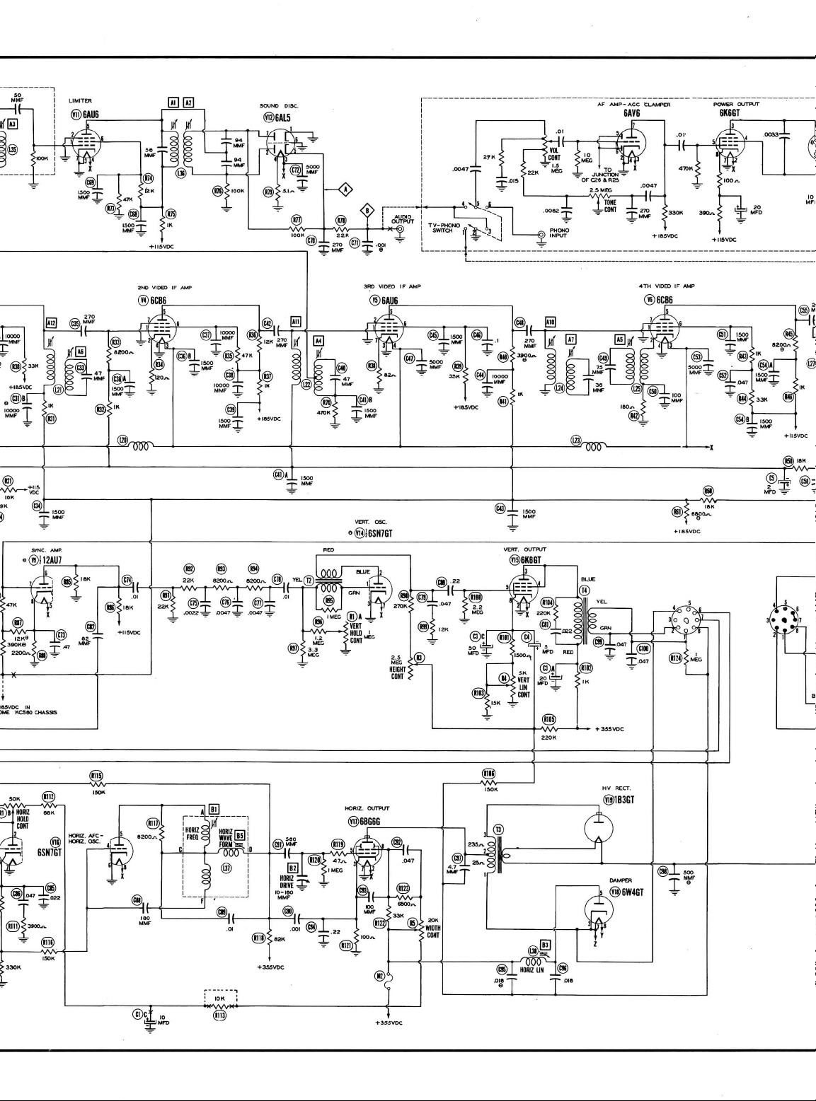
SCHEMATIC - CHASSIS KCS49AT,
T,
KCS60T
9T79
(Ch.
RCA
KCS49,
VICTOR MODELS
A, AT, T),
9T89 (Ch.
9T57,
9T77,
KCS6O,
A, AT, T)
PAGE
3
Page 6

A
PHOTOFACT
STANDARD
©Howord
W.
Sams & Co.,
CHANNEL
NOTATION
Inc.
SW.
SHOWN
®
^T,
SCHEMATIC
1951
IN
CHANNEL 2 POSITION
Osui-
@5U4G
USED
)K,£iv
THE
COOPERATION
RECEIVER
MAKES
IN
IT
POSSIBLE
OF THE
MANUFACTURER
TO
BRING
YOU
THIS
OF
THIS
SERVICE
4-IMVDC
SOME
KC366O CHASSIS
IN
@B
DOTTED
IN
FWTTS
ARE NOT
USED
IN
MODELS.
USED
POINTS MARKED
WHEN DOTTED
IN
X ARE
PARTS
BROKEN.
ALL
ARE
PAGE
4
Page 7
Page 8

r
BLK-RED
®
YOKE
56 <
YEL
6
'TKfi^.
wu I s
270
-L
MMF
SCHEMATIC - CHASSIS
-p
T
IFT
i
4
G
/7Tf5?T1
j
RCA
KCS49,
A,
KCS60
9T79
(Ch.
KCS49,
VICTOR MODELS
A, AT, T),
9T57, 9T77,
9T89
(Ch.
KCS6O,
A, AT, T)
Page 9

PAGE
14
CHASSIS
BOTTOM
VIEW-CAPACITOR
Page 10

R
AND
ALIGNMENT IDENTIFICATION
PAGE
7
Page 11

PAGE
8
CHASSIS BOTTOM VIEW-RESISTOR
A
Page 12

R
AND
INDUCTOR
IDENTIFICATION
PAGE
13
Page 13

SWITCH
VERTICAL
HEIGHT CONTROL
WIDTH
LINEARITY
CONTROL
CONTROL
FOCUS
HORIZONTAL
LINEARITY
HI
HORIZONTAL DRIVE
B2l
HORIZONTAL LOCK
MISCELLANEOUS ADJUSTMENTS
HORIZONTAL
Connect a short
Turn
Turn
single
Turn
Adjust
Adjust
Adjust
optimum
Turn
Turn
Adjust
HORIZONTAL
Remove
Turn
in
the
Turn
Cunnect
Adjust
necessary
Turn
the
picture pulls into synchronization
Turn
Turn
AGC
Inastrongsignal
switch
FM
TRAP
If
interference
interference
SWEEP CIRCUIT ADJUSTMENT
between
the set on and
the
horizontal
vertical
the
hold
the
horizontal drive trimmer
the
width
the
horizontal linearity slug (B3) until
results.
the
hold control
the
hold control clockwise
the
horizontal locking trimmer (B4) until
the
short
the
horizontal
raster.
the
hold control
the
vertical
the
horizontal
during
the
hold control
the
hold control
the
hold control
SWITCH
to the
center
ADJUSTMENT
in the
terminals C and D of
tune
in a TV
hold
control
line
in the
control
WAVEFORM
ADJUSTMENT
is
picture.
1/4
turn
control until picture
fully
counter-clockwise
ADJUSTMENT
from
terminals
hold control
1/4
turn counter-clockwise
input
of an
waveform
adjustment
to
maximum
to
maximum clockwise
1/4
turn counter-clockwise
area
the
normal position
position.
encountered
picture.
CABINET-REAR
L37
clockwise
proper
the
and
the
least
L37,
to
the
the
hold control
hold control
and
of the
signal
FM
.
to
synchronize
as far as
width.
picture
interrupt
number
7 to 9
and
adjust
to
synchronize
terminal
broad
adjust
to
synchronize
switch
areas,
station
and
pattern.
and
is
symmetrical
the
of
bars
the
C of
and
to
keep
momentarily
is
turned clockwise.
Bl
until
is
counter-clockwise.
turn
signal
ADJUST
station, preferably a test
to
maximum clockwise
counter-clockwise
(B2)
is of
and
note
C and D of
fully
clockwise
oscilloscope
slug (B5) until
of B5
turn
counter-clockwise
as the
In
very weak
from a strong
adjust
the
possible
signal
bars
are
present
waveform
the
L37.
narrow
the
the
the
the
it may be
FOR
the
picture.
present
picture.
peaks
picture
blanking
picture.
switch
VIEW
horizontal frequency
without
crowding
from
left
to
right,
by
switching
to
just before
just before pull
slug
of the
remove
clockwise.
possible
EQUAL
another channel
the
(B5) until
waveform
in
synchronization.
the
signal.
bar
appears
If
interference
to
eleminate
PEAKS-
the
picture
in.
the
Adjust
is the
slug
(Bl)
right
slight
blanking
are of
raster.
of the
it by
until
the
side
of the
picture.
readjustment
and
back
pulls
into synchronization.
signal
appears
equal height
B4
until
two
impulse type
adjusting A38.
blanking
of
B2
may be
again.
as a
as
shown
bars
are
is
encountered turn
Adjust
signal
single
in
figure
present
A38 for
appears
required
vertical
9.
just
minimum
as a
for
line
If
before
the
FIG.
9
PAGE
9
Page 14

The
high
The
plug
Remove
tions.
DUMMY
ANTENNA
.
001MFD
.
001MFD
.
001MFD
Use
frequency
DUMMY
ANTENNA
.
001MFD
.
001MFD
Connect
*
NOTE:
have
been reversed.
DUMMY
ANTENNA
Direct
Direct
Direct
Direct
Direct
Direct
Direct
Direct
Direct
voltage shock hazard
on the
focus
the
High
of
to
High
of
side
High
of
to
the
In
High
tube
dummy
(V2).
chassis.
and
converter tube (V2)
SIGNAL
GENERATOR
COUPLING
side
to pin 1
6AU6
(Vll).
chassis.
6AU6
6AU6
chassis.
Low
side
to pin 1
(V10).
Low
to
chassis.
modulated signal
SWEEP
GENERATOR
COUPLING
side
to pin 1
(V10).
Low
negative lead
later
side
shield
Low
productions,
In
those
SWEEP
GENERATOR
COUPLING
to
ungrounded
floating
converter
side
to
of a 3
"
"
"
"
TV
ALIGNMENT INSTRUCTIONS
ALIGNMENT
may be
and
GENERATOR
FREQUENCY
side
SOUND
with
60 % modulation
GENERATOR
side
volt battery
receivers
receivers,
GENERATOR
FREQUENCY
Not
eliminated
replace
SOUND
SIGNAL
21MC
(Unmod.)
IF
ALIGNMENT
SWEEP
FREQUENCY
21MC
(450KC
SWP)
where
A9 is
SWEEP
used
deflection/assembly
(Grid)
(Grid)
(Grid)
over
tube
"
"
"
24MC
(10MC
SWP)
INSTRUCTIONS—
by
removing
must
be in
it
place
with a 6J6
IF
ALIGNMENT USING
CHANNEL
Any
USING
and
450KC
MARKER
GENERATOR
FREQUENCY
21MC
R40 is
tuned
GENERATOR
FREQUENCY
21MC
27MC
19.
»
22.
•24.35MC
21.
25.
22.
21.
24.75MC
25.
26.25MC
VIDEO
junction
1800S2,
to 24.
MARKER
SMC
SMC
75MC
SMC
SMC
85MC
SMC
35MC,
to the
READ
CAREFULLY
the
horizontal
to
operate
which
has pin 1 removed.
AM
SIGNAL
CONNECT
VTVM
DC
Probe thru 1 Meg.
to
Point^X
Common
:o
chassis.
DC
Probe
to
Common
to
chassis.
DC
Probe
thru 1 Meg.
to
PoinK^.
Common
o
chassis.
FM
SIGNAL GENERATOR
sweep.
Use 120 ^ sawtooth voltage
CHANNEL
Any
IF
ALIGNMENT
of R25 and
R45 is
and A10 is
CHANNEL
R26, connect
18KS2
Any
"
"
"
BEFORE
oscillator
the
set.
Potnt^J>.
CONNECT
Vert. Amp.
ffi>.
Low
chassis.
Vert. Amp.
xTJ>.
Low
chassis.
and L26 has
tuned
CONNECT
Use
VTVM
DC
Probe
Common
't.
Amp.
Low
€
ssis.
ATTEMPTING ALIGNMENT
tube
(V16)
from
This
will
disable
GENERATOR
SCOPE
side
side
to 22.
SCOPE
to
"
ADJUST
Al
A2
A3
AND
to
to
to
to
the
been added,
5MC.
to
Poinf@>.
chassis.
Point
Point
positive
AND
VTVM
Detune
Al for
•Adjust
reading will
setting.
Adjust
OSCILLOSCOPE
in
ADJUST
A1.A3
A2
lead
ADJUST
A4,
A6.A7
A8
A9
"
AID
All
A12
to
Point
side
A13,
to
its
socket.
the
local
oscillator
A2 to
maximum counter clockwise.
maximum
deflection.
for
zero
reading. A positive
be
obtained
for
maximum deflection.
scope
for
horizontal
Adjust
for
symmetry
Adjust
A2 so
crossover
retouch
Al
straightness
with
step
to
chassis.
the
frequencies
A5
Adjust
for
Adjust
for
above.
A14
Connect
330fi
R33,
R36,
and
A14 for
figure
3.
Remove
Check
for
figure
4. If
A14
for
proper
and
prevent erroneous indica-
REMARKS
on
either side
deflection.
REMARKS
maximum
amplitude
as per
figure
21MC occurs
lines
as per
maximum
of
crossover
A9 and A10 are
REMARKS
figure
deflection.
deflection.
for
4.
to
which
MINIMUM
maximum
"
carbon
R45.
response
all
necessary
response.
resistors
curve
330ft
retouch
R40 and
response curve
and
negative
of the
1.
at
center
2.
amplitude
lines.
Adjust
similar
resistors.
similar
Adjust
correct
and
of
SLIGHTLY
and
Continue
tuned
See
note
across
A13
to
to
A9
thru
PAGE
1O
FIG.
FIG.5
I
FIG.6
RF
OSCILLATOR
ADJUSTMENTS
Page 15

17.
18.
23.
24.
25.
Remove
the
Disconnect
the
Loosely couple
Connect
the
The
sweep
generator
Set the ine
DUMMY
ANTENNA
Two
120S2
Across
carbon
res.
Connect
VTVM
6.
Repeat
these
Two
120ft
carbon
res.
Check
the
oscillator
by
adjusting
Repeat
step
Across
Two
120ft
carbon
als
lead.
res.
Check
the
voltage
proper
response.
TV
ALIGNMENT
dummy
converter tube
co-ax
link from terminal
the
Irnk
to
negative lead
tuning
als
with
lead.
Across antenna terminals
with
lead.
A26
15.
with
terminal
of the 3 vo t
output
control
to the
SWEEP
GENERATOR
COUPIING
antenna termin-
120R
in
to
Point
D and
retouching
120ft
in
frequency
for
zero voltage
antenna termin-
120ft
in
at
Point
D . If
lead
each
adjust
adjustments
each
for the
each
and
replace
2 of the
2 of the
battery
should
be
mid-position
SWEEP
GENERATOR
FREQUENCY
Not
used
I83MC
(10MC
Not
used
85MC
(10MC
A24 for -3 vo t
until
Not
used
183MC
(10MC
SWP)
213MC
(10MC
Not
used
213MC
(10MC
SWP
207MC
(10MC
201MC
(10MC
195MC
(iOMC
189MC
(IOMC
183MC
(IOMC
177MC
(IOMC
high
at
Point
B .
85MC
(IOMC
necessary
tae
original
tuner
termina
terminal board.
to
terminal
terminated
iwith
of its
range.
MARKER
GENERATOR
FREQUENCY
215.
75MC
181.25MC
SWP)
185.75MC
87.
75MC
83.25MC
SWP)
87.
75MC
reading.
proper
response
185.75MC
181.25MC
185.75MC
211.25MC
215.75MC
SWP)
215.
75MC
211.25MC
215.
75MC
205.
25MC
209.
75MC
SWP)
199.25MC
SWP)
203.75MC
193.25MC
SWP)
197.75MC
187.
25MC
SWP)
191.75MC
81.25MC
SWP)
185.75MC
175.25MC
SWP)
179.
adjust
75MC
channels.
83.25MC
87.'75MC
A24 for -3 vo t
band
SWP)
INSTRUCTIONS
HF
TUNER
ALIGNMENT
6J6 in its
socket.
board
and
connect a 39ft
3 of the
terminal
CHANNE1
13
8
6
6
If
necessary
s
obtained
8
8
13
13
13
12
11
10
9
8
7
oscillator
6
reading.
strip,
Common
Vert.
<@>.
chassis.
DC
Common
Vert.
^^.
chassis.
slightly retouch A21, A22,
with
DC
^J}
chassis.
Vert. Amp.
<K>.
chassis.
DC
Common
Vert. Amp.
^^.
chassis.
is off
Vert.
<^.
chassis.
If A24 is
its
characterist c impedance, usually
If the
SCOPE
VTVM
DC
Probe
SCOPE
Low
Probe
SCOPE
Low
-3
Probe
Common
SCOPE
Low
VTVM
Probe
SCOPE
Low
SCOPE
Low
connect
CONNECT
OR
to
to
Amp.
side
VTVM
to
to
chassis.
Amp.
side
volt
reading
VTVM
to
side
to
to
chassis.
side
frequency,
Amp.
side
adjusted,
carbon
the
VTVM
Pointqp
chassis.
to
to
PoinK^p
to
to
Point
to
to
to
Pointful)
to
to
to
to
resistor
positive lead
50
Point
Point
at
Point
Point
Point
overshoot
Point
turn
CCONTJ
across
to
chassis.
ohms.
ADJUST
A15
Adjust
negative
A16,
A17,
Adjust
A18,
A19
shown
A20
Adjust
A21,
A22,
Adjust
A23
A23 and A17 for
D .
A15
Adjust
negative
side
Readjust
curve,
in
figure
A25
Adjust
midway
shoot
the
required
initial
amplitude.
A26
overshoot
Adjust
proper
Check
response
markers
step
should
compensated
maximum
and
top
of
seems
flatten
A27
adjustment.
the
adjustment
Check
figure
and
channel
selector
terminals
1 and 2
for
zero reading. A positive
reading
will
for
response
in
figure
5.
as in
step
13.
for
response
proper
response
for
zero reading. A positive
reading
of the
same
14.
video
may be
A23 for
will
correct
A16, A17,
frequency
and
5.
for
maximum
between
the
the
adjustment
direction a little more
for
maximum
setting.
Adjust
the
adjustment
A15 to
reset
frequency.
all
high
band
with
markers above 80%.
do not
appear
If A19 is
adjusted,
be
over shot a small
for by
amplitude
markets.
the
curves
on the
deeper
than
the
for
6. If
normal adjust
curve.
In
fixed
and
of A15 and
response
necessary retouch
proper
to
channel
REMARKS
be
obtained
curve
with
bandwidth
similar
to
figure
on
channel
be
obtained
setting.
and A19 for
response
bandwidth
shown
amplitude
of
markers.
Then
of
turning
the
amplitude
A19 for
maximum
as in
the
channels
If the
response.
8 and
step
oscillator
for
within
80%
the
adjustment
amount
adjusting
A25 for
between
the
valley
high
channels
later productions
will
not
require
compensate
curve similar
A21,
readjust
on
on
either
response
slug
than
from
20.
to the
proper
U
repeat
and
sound
in the
A27 to
for it
to
A22,
A16 for
and
6.
and
over-
in
the
Two
120ft
carbon
res.
Turn
channel switch
deeper valley
slight
touch
Disconnect
Across antenna terminals
with
120ft
in
"
to
channel
top. Check
adjustments,
39£i
resistor
each
if
from terminals
the
ead.
up
at the
85MC
(IOMC
Not
8 and
adjust
all
channel for:
necessary.
83.25MC
87.
75MC
SWP)
used
215.
75MC
209.
75MC
203.75MC
197.
75MC
191.
75MC
185.75MC
179.
75MC
87.
75MC
81.
75MC
71.75MC
65.75MC
59.75MC
A24 for
proper
(1)
proper
If A16 and A24 are
1 and 2 on the
6
13
12
11
10
9
SCOPE
Vert.
^>
Low
chassis.
DC
Probe
Common
Amp.
VTVM
e
7
6
5
4
3
2
response.
When
strip
(2)
A24 is
oscillator
and
reconnect
response,
changed considerably, retouch
terminal
to
Point
side
to
to
PoinKg>
to
chassis.
A28
A30
A
A32
A33
A20
A34
properly adjusted
injection
voltage
the
oscillator
the
co-ax
link. Repeat
A35
A36
A37
31
the
at
Check
similar
age at
Also
If
necessary adjust
in
Adjust
negative
curve
Point
D, and (3)
frequency
all low
to
Point D which
recheck
step
13.
for
reading
will
be
steps
11 and 12 of
band channels
figure
6, and the
channels 7 thru
A15 for
zero
reading. A positive
will
slightly
wider
oscillator
on all
channels.
for
injection
should
be -3
zero voltage
be
obtained
with a slightly
frequency.
Video
IF
response
volts.
13.
and
on
either
Make
Alignment.
volt-
as
PAGE
11
Page 16

32.
33.
34.
35.
36.
37.
38.
36.
37.
38.
39.
40.
41.
Remove
the
Turn
Replace
insulated
ANTENNA
.1MFD
the
transformer
secondary.
ANTENNA
.
470O
carbon
res.
Use
ANTENNA
ANTENNA
carbon
res.
plastic
the
tuning
gang
the
plastic cover.
Any
adjusting
Loop should
Volume
Alternate
Connect
During
DUMMY
Connect
schematic.
Alternate
DUMMY
01MFD
.
01MFD
frequency
DUMMY
.
01MFD
.
01MFD
.
01MFD
DUMMY
Two
"
done
be
control
alignment screwdriver
loading
47K£i
resistor
secondary adjustment move
High
side
center
tuning
to
chassis.
Loop
Loop
Loop
two
matched
loading
while
High
side
6AU6
chassis.
High
side
center
tuning
chassis.
modulated signal
High
side
6BA6
chassis.
High
side
616
(V23).
chassis.
120£!
Across
als
with
radio
cover containing
fully
closed.
on the
maintained
should
be at
of the IF
across
SIGNAL
GENERATOR
COUPLING
to
stator
"AM" section
gang.
Low
lOOKSi
is
used
the
secondary
SIGNAL
GENERATOR
COUPLING
to pin 1
(V24).
Low
to
stator
of
"FM" section
gang.
Low
SIGNAL
GENERATOR
COUPLING
to pin 1
(V24).
Low
to pin 5
Low
side
SIGNAL
GENERATOR
COUPLING
FM
antenna termin-
120ft
in
RADIO
Set the
455KC
IP's
in
same
maximum
for
adjusting.
transformers
the
primary
on
of
side
(± 1%)
on
lall
FM
of the
(Grid)
of
side
to
on
of
side
to
with
60 ^ modulation
(Grid)
of
side
to
(Grid)
of
to
each
lead.
ALIGNMENT INSTRUCTIONS
ALIGNMENT
relative position
the
resistors
FM
INSTRUCTIONS-READ
the
dial
scale
dial pointer
will
necessitate
position.
Output
is
used.
of
each transformer
47KS2
resistor
SIGNAL
GENERATOR
FREQUENCY
455KC
(4001,
Mod.)
position
1620KC
1400KC
600KC
FM
IF
ALIGNMENT USING
in
series
transformers except
same
transformer
SIGNAL
GENERATOR
FREQUENCY
10. 7MC
(Unmod.
)
IF
ALIGNMENT USING
and
SIGNAL
GENERATOR
FREQUENCY
10. 7MC
(450KC
SWP)
SIGNAL
GENERATOR
FREQUENCY
90MC
(Unmod.
)
106MC
90MC
and
to the
alignment
to
chassis
of
to
across
BAND
SWITCH
POS.
AM
(third
CW)
from
the
is
BAND
SWITCH
POS.
FM
(fourth
position
CW)
450KC
BAND
SWITCH
POS.
FM
(fourth
position
CW)
BAND
SWITCH
POS.
FM
"
45RPM
calibration
being
CAREFULLY
record
mark
AM
ALIGNMENT
of the 10. 7MC FM
as
when
signal
fl
receiver
generator
while
the
the
primary.
RADIO
DIAL
SETTING
Tuning
gang
fully
closed
Tuning
gang
fully
open
Tune
for
max.
output.
600KC
AM
point
E to
chassis.
discriminator transformer L36.
adjusting.
RADIO
DIAL
SETTING
Tuning
gang
fully
open
FM
SIGNAL
sweep.
Use
RADIO
DIAL
SETTING
Point
of
non-
interference
A
RF
ALIGNMENT
RADIO
DIAL
SETTING
90MC
Tune
for
max.
deflection.
BEFORE
player.
near
the
left
IF's.
is in
cabinet.
should
be no
secondary
of the
OUTPUT
METER
Across
voice
coil
SIGNAL
GENERATOR
The
junction
During
primary adjustment move
CONNECT
VTVM
DC
Probe
to
Point<£\n
chassis.
DC
Probe
F . Common
PoinS^>.
DC
Probe
^K>.
Common
chassis..
GENERATOR
120%
sawtooth voltage
CONNECT
SCOPE
Vert. Amp.
PolnKgX
side
to
Vert. Amp.
Point<^>.
side
to
CONNECT
VTVM
Probe
Common
€
LSSis.
AND
chassis.
chassis.
ATTEMPTING ALIGNMENT
hand
end of the
dial
backplate.
higher
than
necessary
same
transformer
AND
of
these
Connect
to
to
to
Point
to
to
Point
to
OSCILLOSCOPE
to
Low
to
Low
to
Point
to
ADJUST
A39,
A40,
A41,
A42
A43
A44,
A45
A46,
A47
VTVM
ADJUST
A48
A49
A50,
A51,
A52,
A53
in
scope
ADJUST
A48,
A50,
A51
A52,
A53
A49
ADJUST
A
A55,
A56
A57,
A58
is
Adjust
output.
using
Fashion loop
radiate signal into loop
for
Connect a lOKft
"AM"
gang while adjusting
output.
A47
steps
ment
two
resistors
a 680 ohm
the 680 ohm
Adjust
Adjust
negative reading will
either
Adjust
nate loading
for
horizontal
Disconnect
Adjust
symmetry
Reconnect
10.
as per
for
of
54
Expand
imum
Adjust
Expand
mum
to
obtain
an
output
being adjusted.
REMARKS
in the
order given
Then adjust
alternate loading
maximum
section
Remove
while
34 and 35
can be
is
resistor
for
for
side
for
for
7MC
occurs
figure
maximum
crossover
or
deflection.
for
or
deflection.
in
of
several
output.
resistor
of
tuning
A46 for
lOKft
rocking tuning gang. Repeat
until
no
made.
alignment point
across
resistor
REMARKS
maximum
zero reading. A positive
of the
correct
maximum deflection.
as
described above.
deflection.
REMARKS
stabilizer
maximum amplitude
as per
figure
capacitor C106.
at
center
8.
SLIGHTLY
amplitude
lines.
REMARKS
compres s coil turns
maximum deflection.
compress
reading.
Use an
for
maximum
reverse
as
described above.
turns
of
of
receiver.
across
gang. Rock
maximum
resistor
further
G as
the
primary
to
across
deflection.
be
obtained
setting.
capacitor
7.
Adjust
of
crossover
retouch
and
straightness
coil turns
order
wire
and
Adjust
the
center
tuning
and
adjust
improve-
shown
of
each
the
and
on
Use
alter-
C106.
and
A49 so
lines
A48
for
max-
for
maxi-
on
PAGE
12
FIG.
7
FIG.
8
Page 17

A
PHOTOFACT
STANDARD
©Howard
IF=
455
IF=
10.7
H»
Tubi
V22
acBfl
vas
8JO
V24
8BAB
m
flAUfl
V28
V28
V30
NOTATION
W.
Sami & Co., Inc. 1951
OV
-80VDC
OV
KC
MC
Pbl
AM
FM
PV.J
OV
ov
ov
f
TAKEN
SCHEMATIC
WTK
n,a
ov
e.
SVAC
2B5VDC
2H5VDC
VACUUM
ph<
B.3VAC
ov
ov
8
3VAC
2I5VDC
21SVTX-
TUBE
PhS
215VDC
-1.3VDC
Bnvnc
-fl
4VDC
B
7VTK-
«n6
200VDC
-18VDC
18VTM-
R
THE
COOPERATION
RECEIVER
Ph7
ov
ov
K2ypc_
-12VDC
B
3VAC
MAKES
JVS
OV
IT
t TTAKEN
OF THE
POSSIBLE
1,™
V22
V23
V21
V2B
VJfl
VST
V28
VZ9
V30
VII
IN
FM
POSITION
MANUFACTURER
TO
BRING
8CBB
eja
OBAS
BAOe
8AL5
8AV5
5Y3GT
rub.
YOU
.40
3-3KO
10
MH
int.
THIS
Pir
1
OF
SERVICE
88fl
MOKO
00
10KO
on
<o*n
THIS
W*2
P-3
Ph
t
Phj
«»6
P*7
on
-in
•
-2.9KR
.in
on
.in
00
on
10
.10
00
00
„
inf.
4. T
•Z.TKn
*3
Hit.
.«OKfl
5KO
^70KR
Meg.
18KB
•gSKO
tasKn
00
.2.8M«.
68KB
270(1
00
on
esn
1200
llnl
.210KO
3
»KO
in
10
Bt
on
40K(1
n,a
CXHTEO
IN
WKRT5
ARE NOT
USED
IN
MODELS.
USED
POINTS
VWEN
DOTTED
MARKED
X ARE
IN
PARTS
BROKEN.
ARE
ALL
PAGE
22
RADIO SCHEMATIC
-
Page 18

9T79 (Ch.
RCA
VICTOR MODELS
KCS49,
A, AT, T),
9T57,
9T89 (Ch.
9T77,
KCS6O,
A, AT, T)
1C - CHASSIS
RC1092
PAGE
15
Page 19

VI
V2
V3
V4
V5
V6
V7
V8
V9A
V10
Vll
V12
V13
V14A
V15
V16
VI
V18
VI
V20
V21
ITEM
No.
B
B
C
7
9
TV
USE
RF
Amp.
Converter
1st
Video
IF
2nd
Video
IF
3rd
Video
IF
4th
Video
IF
DET. -AGC
Video
AGC
Rest.
Sync.
AGC
Rest.
Sound
Li
Sound
Bias
Vert.
Hor. AVC-Hor.
Osc.
Hor. Output
Damper
HV
LV
Picture
Amp.
Amp.
-Sync.
Amp.
Amp.
-Sync.
IF
Amp.
miter
Discr.
Clamp.
Vert.
Osc. -AGC
Clamp.
Sync. Amp.
Osc.
Vert.
Osc.
Output
Rect.
Rect.
Tube
Rect.
-DC
Sep.
-DC
Sep.
-Vert.
PARTS LIST
TUBES
REPLACEMENT
RCA
PART
No.
6CB6
6J6
6AU6
6CB6
6AU6
6CB6
6AL5
12AU7
12AU7
12AU7
6AU6
6AU6
6AL5
6AV6
6SN7GT
6SN7GT
6J5
6K6GT
6SN7GT
6BG6G
6W4GT
1B3GT
5U4G
19AP4A
(SYLVANIA
DATA
STANDARD
REPLACEMENT
6CB6
616
6AU6
6CB6
6AU6
6CB6
6AL5
12AU7
12AO7
12AU7
6AU6
6AU6
6AL5
6AV6
6SN7GT
6SN7GT
615
6K6GT
6SN7GT
6BG6G
6W4GT
1B3GT
5U4G
19AP4A
AND
DESCRIPTIONS
or
Equivalent)
RMA
BASE
TYPE
6CK
7BF
7BK
6CK
7BK
6CK
6BT
9A
9A
9A
7BK
7BK
6BT
7BT
8BD
BED
6Q
7S
8BD
5BT
4CG
3C
5T
12D
In
Ch.
clamper
Chassis
Chassis
Used
in
KCS49,
and AF
KCS60
KCS49AT,
chassis
NOTES
A, AT, T, V13 is
Amp.
T,
60T
KCS49,
KCS49A
used
as
bias
ITEM
No.
CIA
C2A
C3A
C4
C5
C6
C7
C8
C9
C10A
Cll
C12
C13
C14
C15
C16
C17
CIS
C19
C20
C21
C22
C23
C24
C25A
C26
C27
C28
C29
C30
C31A
C32
C33
C34
C35
C36A
C37
C38
C39
C40
C41A
C42
C43
C44
C45
C46
C47
C48
Capacity
CAPACITORS
values
given
in the
rating
column
are in
mid.
for
and
Paper
Capacitors,
RATING
CAP.
35
35
B
C
10
D
5
35
B
35
C
10
D
5
20
B
80
50
5
2
100
39
270
5000
1500
1500
12
270
270
390
4
15
39
.68
1500
1500
1500
1500
1500
6.8
1500
1500
10000
56
1500
1500
82
10000
10000
1500
47
1500
270
1500
1500
10000
10000
1500
47
1500
1500
270
1500
10000
1500
.1
•
5000
270
200
450
1000
1000
400
1000
C
B
B
B
B
B
VOLT
450
450
450
450
450
450
450
450
450
50
50
75510
75510
75592
28417
73747
75437
75450
75199
73473
75089
75200
75199
75199
75641
75289
45465
75196
71504
75166
73748
75166
75166
75166
75197
75089
73960
71924
73748
73748
73960
73960
73748
73748
73091
75089
73960
73960
73748
75089
73091
73748
73960
73748
73551
73478
73091
RCA
PART
No.
I
"1
and in
AEROVOX
PART
No.
AFH7721J
AFH7721J
AFH4J16E10E
PRS450/4
E26F3
SHOO
SI270
BPD-005
'.BPD-2 x 0015
sin
SI270
SI270
SI390
BPD-0015
SI6. 8NPO
:BPD-2
x
0015
BPD-01
BPD-0015
BPD-0015
BPD-01
BPD-01
BPD-0015
BPD-0015
1468-00025
BPD-2 x 0015
BPD-01
BPD-01
BPD-0015
BPD-2
X0015
1468-00025
BPD-0015
BPD-01
BPD-0015
P488-1
BPD-005
1468-00025
mmfd.
REPLACEMENT
CENTRALAB
PART
No.
D6-101
TCZ-39
D6-271
DD-502
DD-2-152
TCZ-12
D6-271
D6-271
D6-391
TCZ-15
TCN-39
TCZ-.68
DD-152
TCZ-6.8
DD-2-152
DD-103
TCN-56
DD-152
DD-152
TCZ-82
tDD-3-103
DD-152
TCZ-47
DD-152
D6-271
DD-2-152
DD-103
DD-103
DD-152
TCZ-47
DD-2-152
D6-271
DD-152
DD-103
DD-152
DF-104
DD-502
D6-271
for
Mica
DATA
CORNELL-
DUBILIER
PART
No.
UPT420
UPT42G
UPT420
BR445
BBR2-50T
1W5D15
1W5D15
("PTE6S1
IPTE6S1
1W5D15
1W5D15
5W5T25
(1W5D15
(
1W5D15
PTE6S1
PTE6S1
1W5D15
'1W5D15
1W5D15
5W5T25
1W5D15
PTE6S1
1W5D15
PTE4P1
1D5D5
5W5T25
and
PART
GP1K-100
NPOL-39
GP2K-270
811-005
812-2 x 0015
GP1K-12
GP2K-270
GP2K-270
GP2K-390
NPOK-4
NPOK-15
N750L-39
801-0015
NPOK-61.
812-2 x 0015
821-01
N750L-56
801-0015
801-0015
NPOM-82
821-01
821-01
801-0015
NPOM-47
801-0015
GP2K-270
j
812-2 x 0015
821-01
821-01
801-0015
NPOM-47
t
812-2 x 0015
GP2K-270
801-0015
821-01
801-0015
811-005
GP2K-270
Ceramic
ERIE
No.
8
Electrolytic
Capacitors.
SPRAGUE
PART
No.
r
TVL-3785
I
TVA-1702
TVL-3785
TVA-1702
TVL-3709
TVA-1702
TVA-1301
19C11
19C31
29C1
29C6
[
19C22
19C31
19C31
19C5
29C8
29C6
f
36C1
29C8
29C8
"
36C1
36C1
29C8
29C14
29C8
1FM-325
29C6
£
36C1
36C1
29C8
29C14
29C6
j
1FM-325
29C8
36C1
29C8
4TM-P1
29C1
1FM-325
IDENTIFICATION
AND
INSTALLATION
.
Filter
•
Filter
t
Hor.
AFC
V.
Amp. Dec.
.
Filter
•
Filter
•
Filter
Decoupling
-
Vert.
Output Dec.
•
Filter
*
Vert.
Output Cath.
Decoupling
AGC
Filter
RF
Coupling
Fixed
Trimmer
RF
Coupling
AGC
Filter
RF
Amp.
Screen
RF
Amp. Fil.
I
RF
Amp. Cath.
RF
Coupling
RF
Coupling
RF
Coupling
Fixed
Trimmer
Osc.
Feedback
Osc.
Grid
Cap.
Fixed
Trimmer
Conv. Decoupling
Conv.
Filament
Filament
Bypass
RF
Bypass
RF
Bypass
Fixed
Trimmer
RF
Bypass
RF
Bypass
AGC
Filter
Fixed
Trimmer
AGC
Filter
AGC
Filter
Fixed
Trimmer
1st V. IF
Screen
1st V. IF
Plate
1st
V. IF
Fil.
Fixed
Trimmer
RF
Bypass
IF
Coupling
AGC
Filter
2nd
V.
IF
Fil.
2nd
V. IF
Screen
2nd
V. IF
Dec.
RF
Bypass
Fixed
Trimmer
AGC
Filter
1st
S. IF
Grid
IF
Coupling
RF
Bypass
3rd V. IF
Plate
3rd V. IF
Screen
3rd
V. IF
Screen
3rd
V. IF
Fil.
IF
Coupling
Plate
t
CODES
NOTES
Dec.
*
Dec.
Filter
Dec.
»
PAGE
16
Page 20

ITEM
No.
C49
C50
C51
C52
C53
C54A
C55
C56
C57
C58
C59
C60
C61
C62
C63
C64
065
C66
C67
C68
C69
C70
C71
C72
C73
C74
C75
C76
C77
C78
C79
C80
C81
C82
C83
C84
C85
C86
C87
C88
C89
C90
C91
C92
C93
C94
C95
C96
C97
C98
C99
C100
C101
C102
C103
C104
ITEM
R1A
R2A
R3A
H4A
R5A
TV
B
*
f
f
§
No.
B
C
B
B
B
B
*
Additional
Some models
Not
Some models
Some
PARTS
RATING
VOLT
CAP.
75
100
1500
.047
400
5000
1500
1500
270
1000
100
1500
200
.47
10
.1
400
.0015
600
600
.047
400
.015
.0022
600
.1
600
10000
1500
1500
1500
270
.001
600
5000
.47
200
.01
400
.0022
400
.0047
600
.0047
600
.01
600
.047
1000
.22
600
.022
400
82
1000
82
1000
.047
400
.022
400
.47
200
.047
600
180
1000
.01
600
.001
1000
560
500
.047
1000
100
.22
400
.018
1000
1000
.018
4.7
5000
500
20000
.047
1000
.047
1000
.047
400
.047
400
390
500
.0022
600
use
used
in all
models.
use .
models
use
RATING
RESIST-
WATTS
ANCE
1
Meg.
End
Meg.
parts
i
I
i
k
50KS1
Shaft
50KSJ
3500S2
2. 5
Shaft
sooon
Shaft
20KR
Shaft
PART
45469
73748
73553
73478
75089
73091
39396
73748
73787
53511
73551
73598
73592
73797
73595
73557
73960
73748
75166
75166
75244
75249
73478
73787
73561
73595
73920
73920
73594
73597
74957
73562
73090
73090
73553
73562
73787
73592
73102
73594
75643
74250
73597
39396
73794
74727
74727
75646
74154
73597
73597
75071
75071
73904
73595
1500MMF
022MFD
250MMF
I
)
2
T
2
to be
LIST
RCA
No.
I
RCA
PART
[75215
<
(
75216
71440
Not
Req.
71441
Not
Req.
75516
Not
Req.
used with
SI75NPO
SI100NPO
BPD-0015
P488-047
BPD-005
BPD-2X0015
1468-00025
snoo
BPD-0015
P288-47
S110
P488-1
P688-0015
P688-047
P488-015
P688-0022
P688-1
BPD-01
SI1500
SI1500
SI270
P688-001
BPD-005
P288-47
P488-01
P688-0022
P688-0047
P688-0047
P688-01
P1088-047
684-25
P488-022
P488-047
P488-022
P288-47
P688-047
P688-01
P1088-001
1469-0005
P1088-047
SHOO
P488-22
HV20B
P1088-047
P1088-047
P488-047
P488-047
1469-0004
P688-0022
in
this
in
this
application.
in
this
application.
REPLACEMENT
No.
f
"Concentrikit"
AND
CAPACITORS
PART
No.
IRC
PART
No.
Concentrikit
Bll-137
»
Bll-123
«
E-187
•
Qll-239
Not R eq
.
Qll-114
Not
Req.
Qll-119
Not
Req.
REPLACEMENT
DATA
AEROVOX
BPD-0015
application.
DESCRIPTIONS
CCONT.J
DATA
CENTRALAB
PART
TCZ-75
TCZ-100
DD-152
DF-503
DD-502
DD-2-152
D6-271
D6-101
DD-152
D6-100
DF-104
D6-152
DF-503
D6-222
DF-104
DD-103
D6-472
D6-103
DF-503
DF-203
DF-503
D6-561
D6-101
TV1-502
DF-503
DF-503
D6-391
D6-222
")
/
)
CORNELL-
DUBILIER
No.
PART
5R5T1
1W5D15
PTE4S5
1D5D5
(1W5D15
(.1W5D15
5W5T25
5W5T1
1W5D15
GT2P5
5W5Q1
PTE4P1
PTE6D2
PTE6S5
PTE6S15
PTE6D2
PTE6P1
DD-152
D6-152
D6-152
D6-271
D6-102
DD-502
D6-103
D6-222
D6-472
PTE6S1
1W5D15
1W5D15
1W5D15
5W5T25
PTE6D1
1D5D5
GT2P5
PTE4S1
PTE6D2
PTE6D5
PTE6D5
PTE6S1
PTE16S5
GT6P25
PTE6S2
PTE4S5
PTE4S2
GT2P5
PTE6S5
PTE6S1
PTE16D1
5R5T5
GT16S5
5W5T1
GT4P25
GT16S5
GT16S5
PTE4S5
PTE4S5
5R5T4
PTE6D2
CONTROLS
CLAROSTAT
PART
No.
fHTV-65
RTV-191
AM-84-S
FKS-1/4
AM-19-S
FKS-1/4
AM-36-S
FKS-1/4
No.
NPOM-75
NPOM-100
801-0015
811-005
L
812-2
GP2K-270
GP1K-100
801-0015
GP1K-10
GP2L-0015
GP2M-0022
821-01
GP2L-0015
GP2L-0015
GP2K-270
GP2L-001
811-005
821-01
GP2M-0022
GP2M-0047
GP2M-0047
821-01
GP2K-560
GP1K-100
GP2K-390
GP2M-0022
CENTRALAB
PART
No.
SBB-510
SBB-511
AN-83
AK-1
AN-10
AK-1
AN-22
AK-1
ERIE
PART
No.
XC015
801-0015
INSTALLATION
Attach
(Continued)
IDENTIFICATION
SPRAGUE
PART
No.
36C10
29C8
4TM-S47
29C1
29C6
f
1FM-325
19C11
29C8
2TM-P47
19C3
4TM-P1
6TM-D15
6TM-S47
6TM-S15
6TM-D22
6TM-P1
36C1
29C8
29C8
29C8
19C31
6TM-D1
29C1
2TM-P47
4TM-S1
6TM-D22
6TM-D47
6TM-D47
6TM-S1
MB-S5
6TM-P25
4TM-S22
4TM-S47
4TM-S22
2TM-P47
6TM-S47
6TM-S1
MB-D1
MS-35
MB-S5
19C11
4TM-P22
MB-S5
MB-S5
4TM-S5
4TM-S5
MS-34
6TM-D22
Vert,
hold control-front
Horiz. hold
Attach
per
instr.
Brightness
control
Contrast
control-rear
Height
control
Attach
to R3A per
Vert,
linearity
Attach
to R4A per
Width
control
to R5A per
NOTES
control-rear
AND
INSTALLATION
Fixed
Trimmer
4th
V. IF
Cath.
4th
V. IF
Screen
4th
V. IF
Screen
4th
V. IF
Fil.
4th
V. IF
Plate
RF
Bypass
IF
Coupling
IF
Coupling
AGC
Filter
AGC
Filter
V.
Diode
Filter
Video
Coupling
V.
Amp. Cath.
Video Coupling
Video Coupling
DC
Res. -Sync. Sep.
Grid.
Pic. Tube Cath.
IstS.
IF
Dec.
IstS.
IF
Cath.
Limiter
Decoupling
Limiter
Screen
RF
Bypass
De-emphasis
Discr.
Fil.
Sync. Amp. Cath.
Vert.
Sync. Coupling
Integrator Net.
Integrator
Integrator
Vert.
Osc. Grid
Vert.
Discharge
Vert.
Sweep Coupling
Fixed
Trimmer
Hor. Sync. Coupling
Hor. Feedback
AFC
Filter
AFC
Filter
AFC
Filter
Hor.
AFC
Hor. Osc. Grid
Fixed
Trimmer
Hor.
Fischarge
Hor. Sweep Coupling
Hor. Output Screen
Hor.
Output
Hor.
Output
Damper
Filter
Damper
Filter
Fixed Trimmer
HV
Filter
Fixed
Trimmer
Fixed Trimmer
Line
Filter
Line
Filter
Video
Coupling
Sync.
Coupling
in
"Concentrikit".
-front
instructions
control
instructions
instructions
Net.
Net.
Plate
§
CODES
NOTES
Dec.
t
Screen
Cath.
f
a*
*"
.
Nl
8s
>
>
8
R6
R7
R8
R9
RIO
Rll
R12
R13
R14
R15
R16
ITEM
No.
RATING
RESISTANCE
3900SJ
27S2
22KS2
3300S2
3900SJ
ison
20%
lOOKfi
20%
820052
100KS2
rooKn
10KO
20%
WATTS
2
i
1
|
~
^
|
2
i
B
*
REPLACEMENT
RCA
PART
No.
DATA
IRC
PART
BTS-3900
BTS-3300
BTS-3900
BTS-150
BTS-100K
RESISTORS
No.
ALL
Antenna
RF
RF
RF
AGC
AGC
Series
RF
Mixer
Osc. Grid
Osc.
RESISTORS
Coil
Shunt
Amp. Cathode
Amp.
Screen
Amp.
Plate
Network
Network
Test
Point
Coil
Shunt
Grid
Plate
IDENTIFICATION
ARE t 10%
CODES
UNLESS OTHERWISE STATED.
PAGE
17
Page 21

R17
R18
R19
R30
R21
R22
R23
R24
R25
R26
R27
R28
R29
R30
R3l
R32
R33
H34
R35
R36
R37
R38
R39
R40
R41
R42
R43
R44
R45
R46
R47
R48
R48
R50
R51
R52
R53
R54
R55
R56
R57
R58
R59
R60
R61
R62
B63
R64
H65
R66
H67
R68
R69
R70
R71
«72
R73
R74
H75
K76
R77
R78
R79
R80
R81
R82
R83
R84
R85
R85
R87
R88
R89
R90
R91
R92
R93
R94
R95
R96
R97
R98
R99
R100
R101
R102
R103
RIO
R105
R106
R107
R108
R109
R110
Rill
RI12
R113
R114
R115
R116
R117
RI18
R119
ITEM
No.
4
RATING
RESISTANCE
lOKn
5%
2.2
Meg.
100!!
20%
100!!
20%
10K!!
39K!!
39K!1
39K!1
33KR
iooon
20%
470!!
10K!!
120!!
33KB
IOOOB
20%
IOOOB
20%
8200!!
5%
120B
47KO
20%
12K!!
5%
iooon
20%
82!!
33Kn
3900B
5%
iooon
20%
ison
1000!!
20%
33K8
8200!!
5%
iooon
20%
5600!!
5%
33K!!
20%
18KB
18KB
47KB
390KB
ISOKn
220!!
100K!1
4700B
5%
560KS!
220!!
6800!!
18KB
6800!!
4700n
56K!1
470K!!
56KB
lOOKn
47001!
820Kn
150K!!
470K!!
821!
iooon
20%
47KB
12K!!
iooon
20%
lOOKn
5%
100KB
5%
22KB
5.
in
47KB
390K!!
5600B
220KB
220KB
18Kn
18KH
12KH
2200!!
20%
10KB
lOKn
22K!1
22KB
8200!!
8200n
I
Meg.
20%
1.2
Meg.
3.3
Meg.
270Kn
12Kn
5%
2.2
Meg.
isoon
iooon
20%
i5Kn
220Kn
220Kn
isOKn
330KB
820Kn
82K!i
330Kn
5%
3900n
68Kn
lOKn
82Kn
150KB
ISOKn
5%
8200n
5%
82Kn
5%
47020%
5%
5%
WATTS
I
1
\
2
2
2
i
3
2
1
i
f
I
1
1
2
2
a
JL
1
i
i
£
2
2
2
2
I
L
i
2
Z
-i|
2
|
I
3
|
|
f
1
2
1
2
3
2
2
2
T
2
1
2
k
i
|
i
X
I
I
2
1
^
£
5
I
2
2
2
I
2
i
^
|
1
1
1
3
i
I
I
2
i
I
\
i
I
2
k
\
1
1
i
1
i
1
1
1
i
1
i
REPLACEMENT
RCA
PART
72067
No.
RESISTORS
DATA
IRC
PART
No.
BTS-2.2
Meg.
BTS-100
BTS-100
BTB-10K
BTB-39K
BTB-39K
BTB-39K
BTS-33K
BTS-1000
BTA-470
BTS-120
BTS-1000
BTS-1000
BTS-120
BTS-1000
BTS-82
BTB-3900-5%
BTS-1000
BTS-180
BTS-1000
BTS-33K
BTS-8200-5%
BTS-1000
BTS-5600-5%
BTS-33K
BTS-18K
BTS-18K
BTS-47K
BTS-390K
BTS-150K
BTS-220
BTS-100K
BTS-4700-5%
BTS-560K
BTS-220
BTA-6800
BTB-18K
BTS-4700
BTS-56K
BTS-470K
BTS-56K
BTS-100K
BTS-4700
BTS-820K
BTS-150K
BTS-82
BTS-1000
BTS-47K
BTS-12K
BTS-1000
BTS-100K-5%
BTS-100K-5%
BTA-22K
BW-j-5.1
BTS-47K
BTS-390K
BTS-5600
BTS-220K
BTS-220K
BTS-18K
BTB-I8K
BTS-12K
BTS-2200
BTS-10K
BTS-10K
BTA-22K
BTA-22K
BTS-8200
BTS-82
00
BTS-1
Meg.
BTS-1. 2 Meg-
BTS-3.3
BTS-270K
BTS-12K-5%
BTS-2.2
BTA-1500
BTS-1000
BTS-15K
BTS-220K
BTS-220K
BTS-150K
BTS-330K
BTS-820K
BTA-82K
BTA-330K-5%
BTS-3900
BTA-68K
BTS-10K
BTA-82K
BTA-150K
BTA-150K-5%
BTS-8200-5%
BTA-82K-5%
Meg-
Meg.
ca
VTO
5%
CCONT.J
IDENTIFICATION
Converter Transformer
Voltage Divider
Decoupling
Decoupling
Voltage
Divider
Voltage Divider
Voltage
Divider
Voltage
Divider
AGC
Network
AGC
Network
1st
Video
IF
Transformer Shunt-See Note
1st
Video
IF
Transformer
1st
Video Amp. Cathode
1st
Video Amp.
Plate
AGC
2nd
2nd
2nd
2nd
2nd
3rd
3rd
3rd
3rd
4th
Video
4th
Video
4th
Video
4th
Video
4th
Video
AGC
AGC
AGC
AGC
Voltage
AGC
Video
Voltage Divider
Video
Video
Video
Video
Video
Decoupling-See
Isolation
AGC
AGC
AGC
AGC
Isolation-See
Picture Tube Grid
Picture Tube Cathode
Sound
Sound
Sound
Voltage
Limiter
Limiter
Discriminator Diode
Discriminator Diode Load
De-emphasis
Discriminator Filament-Wire
Sync.
Voltage Divider-See Notes
Voltage Divider-See Notes
Sync.
Voltage Divider-See Notes
Voltage
Sync. Amp.
Voltage
Sync.
Isolation-See
Peaking Coil Shunt-See Notes
Voltage Divider
Integrator
Integrator
Integrator
Vert.
Voltage
Vert. Osc. Grid
Vert. Osc.
Vert.
Output
Vert.
Vert.
Vert.
Damping
Voltage Divider
Voltage
Horiz.
Horiz.
Horiz.
Horiz.
Horiz.
Horiz.
Horiz.
Voltage
Horiz.
Horiz. Osc. Grid
Horiz.
Horiz.
Parasitic
Screen
Decoupling
Network
Video
IF
Amp. Grid
Video
IF
Amp. Cathode
Video
IF
Amp.
Video
Video
Video
Video
Video
Video
Video
Detector Diode Load
Rectifier
Network
Network
Network
Network
Amp. Cathode
Amp.
Amp.
Amp. Cathode
Amp.
Amp. Decoupling
Amp. Grid
Amp. Cathode-See Note
Amp.
Amp.
IF
IF
IF
Separator
Separator
Amp. Cathode
Osc. Transformer
Peaking
Grid
Output
Output
Linearity Control
AFC
AFC
AFC
AFC
AFC
AFC
AFC
AFC
Transformer
Osc.
Screen
IF
Amp.
Plate
IF
Amp. Decoupling
IF
Amp. Cathode
IF
Amp.
Screen
IF
Amp.
Plate-See
IF
Amp.
Plate
IF
Amp. Cathode
IF
Amp.
Screen
IF
Amp.
Screen
IF
Amp.
Plate-See
IF
Amp.
Plate
Plate
Divide'r-See Note
Plate
Grid
Plate
Note
2
Plate-See
Plate-See
Note
9
Grid
Cathode
Decoupling
Divider
Screen
Decoupling
Divider
Divider-See
Divider
Divider
Divider
Plate
Cathode-See Notes
Plate
Notes
9 and 12
Plate
Cathode
Decoupling
Grid
Grid
Cathode
Cathode
Filter
Plate
Plate
Filter
Plate
Suppressor
Load
Note
Shunt
CODES
Shunt
6
7
9 and 12
1
12
Shunt-See Note
Note
Decoupling
Decoupling
Note
Decoupling
10
s 8, 10 and 12
Notes
9 and 12
Notes
9 and 12
Wound
3, 4 and 5
9 and 12
9 and 12
11
9 and 12
Shunt
• .
Shunt
TV
PARTS
ITEM
No.
RESISTANCE
R120
1
Meg.
loon
RI21
RI22
33KB
R123
6800!!
R124
1
Meg.
4ooon
R125
56KB
R126
R127
56KB
R128
56KB
RI29
lOKn
lOKn
R130
8000B
R13I
R132
100KB
27KB
R133
1.
Some
Note
2.
Some
Note
3.
Late
Note
4.
Late production
Note
5.
Used only
Note
6.
Late
Note
7.
Late production models
Note
8.
Late
Note
9.
Used only
Note
Note
10.
Chassis
Note
11.
Not
Note
12.
Not
13.
Some
Note
ITEM
No.
PRI.
Tl
117VAC
®
1.5A
ITEM
No.
DC
RESISTANCE
PRI.
T2
165!!
T3
26on
Tap®
T4
465B
T5A
13.
5B
B
43!!
i
Drill
ITEM
No.
IMPEDANCE
PRI.
T7
7.8KB
ITEM
No.
FIELD
PM
SP1
CONE
11
1/2"
SP2
ITEM
TOTAL
No.
DIRECT
CURRENT
LI
.200ADC
RATING
WATTS
£
2
2
1
\0
1
1
1
2
2
10
20%
2
2
models
use
models
use
production
in
late
production models
production models
in
chassis
KCS60T
used
in
chassis
used
in all
models
use a
RATING
SEC.
1
720VCT
.
200ADC
RATING
SEC.
1310B
on •
.4B
one new
mounting
RATING
DC
SEC.
PRI.
4.7B
soon
CT
RATINGS
RES.
V. C.
4.2B
DIA.
V. C.
1"
RATINGS
D.
C.
RESISTANCE
45B
LIST
REPLACEMENT
RCA
PART
No.
75512
75593
680U
resistor
parallel
resistors
models
use 1.2
models
use
390KS2
production models.
use
1800&
use
18KJ2
use
560KSI
KCS60T.
uses
220KS
resistor
KCS60T.
models.
15KS7, 2 watt
SEC.
2
5VAC
® 3A
RES.
IMP.
DIA.
SEC.
6.3VAC
®
1.2A
SEC.
6.3VAC
® 8A
TRANSFORMER
RCA
PART
No.
74144
75585
74950
74952
hole.
TRANSFORMER
SEC.
.5B
75557
RCA
PART
75681
75682
INDUCTANCE
(0
CURRENT
VXO-f)
. 8
Henries
AND DES
RESISTOR:
DATA
IRC
PART
No.
BTS-1 Meg.
BW-2-100
BTS-33K
BTA-6800
BTS-1
Meg.
1
3/4A-4000
BTA-56K
BTA-56K
BTA-56K
BTB-10K
BTB-10K
1
3/4A-8000
BTB-100K
BTB-27K
in
this
application.
in
this
Meg.
4
RCA
PART
appticatiot
resistor
in
resistor
resistor
resistor
resistor
and two
this
in
this
in
this
appli
in
this
applii
in
this
in
this
applicatii
12KS2
, 2
TRANSFORMS
RCA
3
PART
No.
75508
(S1
REPLACEME
STANCOR
PART
No.
A-8121
©
REPLACEM
STANCOR
PART
SPEAK
REPLACEMENT
JENSEN
PART
ST-101
MOD. P12-T
No.
No.
No.
No.
FILTER
RCA
PART
No.
73154
app!
app]
wa
DAI
C
a
F
PAGE
18
Page 22

MTIFICATION
mer
Shunt-See Note
mer
Shunt-See
•id
ithode
reen
ate
•coupling
Ihode
reen
ate-See Note
a!e
Decoupling
thode
reen
reen
Decoupling
ite-See
Note
ate
Decoupling
Load
ee
Notes
8, 10 and 12
Notes 9 and 12
Notes
9 and 12
CODES
Note
6
7
TV
PARTS
RESISTANCE
1
100J!
33Kn
6800E1
1
4000S!
56Kn
56Kn
56KH
10KS!
10KS1
aooon
loonn
27Kn
117VAC
®
1.5A
DC
lesn
260S1
Tap
255!
465n
is.
43n
CD
Drill
Meg.
Meg.
PRI.
PRI.
RATING
20%
Some models
Some
models
Late
production,
Late
production
Used only
Late
production
Late
production
Late
production models
Used only
Chassis
Not
used
Not
used
Some
models
720VCT
.200ADC
RATING
RESISTANCE
I3ion
on
®
.4n
5n
one new
ITEM
No.
R120
R121
R122
R123
R124
R125
R126
R127
R128
R129
I
12
R130
R131
R132
R133
ITEM
Tl
ITEM
No.
T2
T3
T4
T5A
N(
No
No
No
No
Note
Note
Note
Note
Note
Note
Note
Note
No.
B
WATTS
2
B
1
1.
10
1
1
1
2
2
10
2
2
use
use
models
models
in
late production
models
models
in
chassis
KCS60T
in
chassis
in all
models.
use a
RATING
SEC.
1
SEC.
mounting
LIST
AND
REPLACEMENT
RCA
PART
No.
75512
75593
680J1
resistor
resistors
use
1.2
use
390KJ2
models.
use
180012
use
18Kfi
use
560KS2
KCS60T.
220KJ3
resistor
KCS60T.
15KS2, 2 watt
2
SEC.
6.3VAC
®
1.2A
SEC.
6.
3VAC
® 8A
in
Meg.
parallel
uses
SEC.
5VAC
® 3A
TRANSFORMER
RCA
PART
No.
74144
'
75585
74950
74952
hole.
DESCRIPTIONS
RESISTORS
DATA
IRC
PART
No.
BTS-1
Meg.
BW-2-100
BTS-33K
BTA-6800
BTS-1 Meg.
1
3/4A-4000
BTA-56K
BTA-56K
BTA-56K
BTB-10K
BTB-10K
1
3/4A-8000
BTB-100K
BTB-2TK
this application.
in
this application.
resistor
in
in
PART
A-8121
in
in
this
I2Kfi
PART
75508
in
CD
this application.
in
this
application.
this
application.
this application.
this
application.
application.
, 2
watt
RCA
No.
(SWEEP
REPLACEMENT
No.
resistor
resistor
resistor
resistor
and two
TRANSFORMER
3
4
CCONT.I)
IDENTIFICATION
Horiz. Output Grid
Horiz. Output Cathode
Horiz. Output Screen
Voltage Divider
Voltage
Divider
Voltage
Divider-Wire
Voltage Divider
Bleeder
-See
Note
-See
-See
-Wire
Divider
Note
Note
Wound
in
parallel
13
13
13
13
Bleeder
Bleeder
Bleeder-See Note
Filter
Isolation
Voltage
resistors
(POWER)
REPLACEMENT
STANCOR
PART
No.
CIRCUITS)
DATA
PART
No.
A-4000
CD
TBO-2
A-3035
(Continued)
CODES
Wound
to
replace
R127, R128, R129,
DATA
MERIT
PART
No.
P-3070
PART
No.
Vert.
Block Osc.
Vert. Output
Horiz. Deflection Coil
Vert.
Deflection Coil
CHICAGO
TP370
and
PART
Trans.
R130.
No.
Trans.
L2
L3
L4
L5
L6
L7
L8
L9
L10
LI1
L12
L13
L14
L15
LI
LIT
LIB
L19
L20
L21
L22
L23
L24A
L25
L26
L27
L28
L29
L30
LSI
L32
L33
L34
L35
L36
L37
L38
ITEM
Ml
ITEM
No.
No.
6
B
USE
Ant.
Coil
Ant.
Coil
IF
Trap
IF
Trap
Ant.
Coil
Shunt
FM
Trap
Ant.
Coils
Fil.
Choke
RF
Coils
RF
Coil
Mixer Grid
Coils
Mixer Grid
Osc.
Coils
Fil. Choke
Mixer
Plate
Loading Coil
RF
Choke
Conv.
Trans.
1st
Video
IF
Fil. Choke
2nd
Video
IF
3rd
Video
Fil. Choke
4th
Video
4th
Video
Sound
Trap
RF
Choke
5th
Video
Peaking
Peaking
Peaking
Peaking
Peaking
4.
SMC
Trap
Peaking
Sound
IF
Disc.
Trans.
Horiz.
Osc.
Trans.
Horiz.
Lin.
BASE
TYPE
Bayonet
DC
RES.
PRI.
SEI
.6C
.6n
.en
.es;
.252
.20
on
on
on
on
on
OS!
OS!
on
on
OS!
on
.3S1
.2n
.4n
.2S1
en
on
.in
.2n
on
.in
.IS!
.4S1
sn
sn
2.6S1
sn
2.6n
I2n
.sn
.IS!
130S!
ssn
on
.IE
on
.in
37f
VOLTS
6-8
IF
IF
IF
IF
nt-Wire
lotes
lotes
•de-See
lotes
and 12
>e
Notes
Wound
3, 4 and 5
9 and 12
Notes
9 and 12
9 and 12
9 and 12
ITEM
No.
T7
ITEM
No.
SP1
SP2
ITEM
No.
LI
IMPEDANCE
PRI.
7.8Kn
FIELD
PM
CONE
11
1/2"
TOTAL
DIRECT
CURRENT
.200ADC
4.
RES.
DIA.
RATING
SEC.
7S!
RATINGS
DC
RES.
PRI.
soon
CT
V. C.
IMP.
4.2H
V. C.
DIA.
1"
RATINGS
D.
C.
RESISTANCE
45S1
TRANSFORMER
RCA
SEC.
PART
75557
RCA
PART
No.
75681
75682
INDUCTANCE
[0
CURRENT
1000
./"I
. 8
Henries
No.
.sn
REPLACEMENT
STANCOR
PART
SPEAKER
REPLACEMENT
JENSEN
PART
ST-101
MOD.P12-T
FILTER
RCA
PART
No.
73154
(AUDIO
PART
No.
A-3020
DATA
No.
CHOKE
REPLACEMENT
STANCOR
PART
DATA
MERIT
No.
QUAM
PART
I2A4
No.
No.
OUTPUT)
CHICAGO
PART
No.
DATA
MERIT
PART
No.
C-2996
CHICAGO
PART
TR-3300
INSTALLATION
NOTES
INSTALLATION
No.
NOTES
NOTES
ITEM
No.
M2
M3
M4
MSA
B
M6A
M7
B2, B4
B
C
PART
Fuse
RF
Tuner
Switch
Switch
Switch
Focus
magnet
Focus
magnet
Focus
magnet
Ion
trap
Ant. Matching
Trimmer
Safety
Glass
Escutcheon
Knob
Knob
Knob
Knob
Knob
NAME
Unit
Page 23

OPTIONS
:ONTJ
-iz.
Output
Grid
•iz.
Output
Cathode
•iz.
Output
Screen
tage
Divider
tage
Divider
tage
Divider-Wire
Itage
Divider
:eder-See
Note
;eder-See
Note
ieder-See
Note
.•eder-See
Note
ter-Wire
Wound
lation
Itage
Divider
sistors
in
parallel
(POWER)
REPLACEMENT
STANCOR
PART
No.
!EP
CIRCUITS)
ATA
MERIT
ART
No.
1000
©
i035
(Continued)
IDENTIFICATION
Wound
13
13
13
13
lo
CHICAGO
PART
TBO-2
replace
DATA
PART
P-3070
No.
MERIT
R127,
No.
CODES
R128, R129,
Vert.
Horiz.
Vert.
Horiz.
Vert.
CHICAGO
PART
TP370
NOTES
Block
Osc. Trans.
Output
Output
Trans.
Deflection
Deflection
and
No.
Trans.
Coil
Coil
R130.
L2
L3
«
L5
L6
L7
L8
L9
L10
Lll
L12
L13
L14
LI
L16
LIT
L18
L19
L20
L21
L22
L23
L24A
L25
L26
L27
L28
L29
L30
L3]
L32
L33
L34
L35
L36
L37
L38
ITEM
Ml
ITEM
No.
,
5
No.
Ant.
Ant.
IF
IF
Ant.
Shunt
FM
Ant.
Fil.
RF
RF
Mixer
Coils
Mixer
Osc. Coils
Fil.
Mixer
Loading
RF
Conv.
1st
Fil.
2nd
3rd
Fil.
4th
4th
B
Sound
RF
5th
Peaking
Peaking
Peaking
Peaking
Peaking
4.
Peaking
Sound
Disc.
Horiz.
Trans.
Horiz.
Bayonet
Coil
Coil
Trap
Trap
Coil
Trap
Coils
Choke
Coils
Coil
Choke
Choke
Video
Choke
Video
Video
Choke
Video
Video
Choke
Video
SMC
BASE
USE
Grid
Grid
Plate
Coil
Trans.
IF
IF
IF
IF
IF
Trap
Trap
IF
Trans.
Osc.
Lin.
TYPE
COILS
(RF-IF)
DC
RES.
PRI.
SEC.
.en
.6!!
.6n
.20
.2!!
on
Of!
on
OS!
on
on
on
on
on
.en
73591
73591
75242
75242
75241
75449
75180
73477
75179
75183
75187
75182
75175
RCA
PART
REPLACEMENT
No.
on
on
.sn
.4n
.2n
on
.in
.2n
on
.in
.in
.4n
IF
sn
5S!
2.
en
sn
2.
en
i2n
.sn
.in
ison
ssn
.2n
en
on
.in
on
an
3 TO
75185
75202
75181
74589
73477
74590
75209
73477
74592
73574
71778
76011
75210
75299
75253
71793
73253
75251
75252
75211
75212
75213
71449
DIAL
AMPS.
.2
COLOR
White
BEAD
VOLTS
6-8
MEISSNER
PART
No.
19-1921
19-1923
19-1921
19-1923
LIGHTS
REPLACEMENT
RCA
PART
No.
11765
DATA
PART
CLA
DATA
IRC
No.
NOTES
Stator
complete
with
rotor,
with
rotor,
trimmer
with
rotor,
C14
with
rotor,
white
selector
No.
dots,
dot
coils,
coils,
coils,
coils,
dots
dots
light
R6,
RIO,
Rll,
C8, C9
Stator complete
R9, C13
Includes
.8-3.8
Stator complete
R12,
R13, R14, C12,
Includes
.8-3.8
Stator complete
C16,
C18
Wound
.
56
With
With
Sound
With
With
Includes
36
microhenries,
used
36
microhenries, orange-white dots
120
microhenries, blue-red
36
microhenries, black
500
(chassis
120
microhenries, blue-red
500
Type
trimmer
on
coax cable, part
microhenries
trap
trap
take
off
trap
trap-alternate
C49
in all
models.
microhenries, green-white dots,
KCS60T)
microhenries, green-white dots
NOTES
#51,
channel
75201
not
NJ
O
sr
00
CO
o
o
3IO
OUTPUT)
DATA
WERIT
,RT
No.
1020
QUAM
'ART
No.
OKE
iCEMEN'
ICOR
No.
CHICAGO
PART
DATA
MERIT
PART
C-2996
No.
No.
CHICAGO
PART
No.
TR-3300
INSTALLATION
INSTALLATION
NOTES
NOTES
ITEM
No.
M2
M3
M4
MSA
B
M6A
M7
B2.B4
B
C
PART
Fuse
RF
Tuner
Switch
Switch
Switch
Focus magnet
Focus magnet
Focus magnet
Ion
trap
Ant.
Matching
Trimmer
Safety
Glass
Escutcheon
Knob
Knob
Knob
Knob
Knob
NAME
Unit
MISCELLANEOUS
RCA
PART
No.
73600
75594
75692
76010
75584
75504
75935
74953
75509
75217
75619
75455
73996
74959
74962
74963
74969
.25A
250V
Type
BEL
Dial light
AGC
AGC
(alternate)
Has
green
dot
Includes
connector,
Dual(horiz.
drive,
horiz.
Channel
selector
Channel
selec
Fine
Vert,
Horiz.
Light
tor, maroon
tuning,
maroon
hold, brightness, maroon
hold,
contrast,
switch, maroon
NOTES
L2, L3, L4, L5, L6, L7, C6, C7
lock
10-160MMF)
maroon
8
PAGE
19
Page 24

V22
V23
V24
V25
V26
V27
V2B
V29
V30
V31
ITEM
No.
RADIO
USE
RF
Amp.
Converter
1st FM AM IF
2nd
FM IF
Ratio Det.
DET.
-AVC-AF
Phase
Inv.
Power
Output
Power Output
Rectifier
PARTS
TUBES
REPLACEMENT
RCA
PART
No.
6CB6
616
6BA6
6AU6
6AL5
6AV6
6C4
6V6GT
6V6GT
5Y3GT
LIST
AND
(SYLVANIA
DATA
STANDARD
REPLACEMENT
6CB6
616
6BA6
6AU6
6AL5
6AV6
6C4
6V6GT
6V6GT
5Y3GT
DESCRIPTIONS
or
Equivalent)
RMA
BASE
TYPE
6CK
7BF
7BK
7BK
6BT
7BT
6BG
7AC
7AC
5T
NOTES
ITEM
No.
C105A
C106
C107
C108
C109
C110
CHI
C112
C113
C114
C115
cue
C117
C118
C119
C120
C121
C122
C123
C124
C125
C126
C127
C128
C129
C130
C131
C132
C133
C134
C135
C136
C137
C138
C139
C140
C141
C142
C143
C144
C145
C146
C147
C148
C149
B
C
*
t
f
RATING
CAP.
30
30
40
2
220
5000
5000
100
470
15
68
68
3
150
5
5000
5000
47
5000
39
.05
5000
5000
5000
150
150
5000
5000
.005
330
330
.005
.005
1800
.001
1500
.018
.015
.02
100
.005
.01
.02
150
.001
.001
5000
Not
used
in
When either
Some
models
VOLT
450
350
25
50
500
200
200
500
500
100
200
200
200
200
100
400
400
400
1200
1200
all
models.
items
use
Capacity
and
Paper
RCA
PART
72052
73747
75611
73473
73473
39396
72571
39044
75612
75612
74733
75614
75612
73473
73473
75609
73473
73553
73473
73473
73473
75614
75614
73473
73473
71926
39640
39640
71926
71926
75610
73801
75610
58476
72120
74010
75437
71926
71925
74010
75614
70642
70642
73473
C132
1500MMF
No.
or
C133
in
values
given
Capacitors,
AEROVOX
PART
AFH6J10I8A
E26F3
SI220
BPD-005
BPD-005
SHOO
1468-0005
SI15
SI68
SI150
SI5N750
BPD-005
BPD-005
SI47
BPD-005
P288-05
BPD-005
BPD-005
BPD-005
SI150
SI150
BPD-005
BPD-005
P688-005
1468-0003
1468-0003
P688-005
P688-005
SI1800
P688-001
SI1500
P488-015
P488-02
snoo
P688-005
P488-01
P488-02
SI150
P1688-001
P1688-001
BPD-005
are
replaced,
this
application.
in the
and in
No.
replace
REPLACEMENT
CENTRALAB
CAPACITORS
rating
column
mmfd.
for
Mica
DATA
CORNELL-
No.
both with
DUBILIER
PART
No.
UP3345V4
BBR2-50T
5W5T25
1D5D5
1D5D5
5W5T1
5W5T5
5W5T15
1D5D5
1D5D5
5W5Q5
1D5D5
PTE4S5
1D5D5
1D5D5
1D5D5
5W5T15
5W5T15
1D5D5
1D5D5
PTE6D5
5W5T3
5W5T3
PTE6D5
PTE6D5
PTE6D1
1W5D15
PTE6S15
PTE4S2
5W5T1
PTE6D5
PTE4S1
PTE4S2
5W5T15
PTE16D1
PTE16D1
1D5D5
capacitors
PART
D6-221
DD-502
DD-502
D6-101
D6-471
D6-150
TCN-68
TCN-68
D6-151
DD-502
DD-502
D6-470
DD-502
TCN-39
DF-503
DD-5C2
DD-502
DD-502
D6-151
D6-151
DD-502
DD-502
D6-502
D6-331
D6-331
D6-502
D6-502
D6-182
D6-102
D6-152
DF-203
D6-101
D6-502
D6-103
DF-203
D6-151
DD-502
are in
and
GP2K-220
811-005
811-005
GP1K-100
GP2K-470
GP1K-15
N750L-68
N750L-68
N220K-3
GP2K-150
N750K-5
811-005
811-005
GP1K-47
811-005
N750L-39
811-005
811-005
811-005
GP2K-150
GP2K-15C
811-005
811-005
811-005
GP2K-330
GP2K-330
811-005
811-005
GP2M-0018
GP2L-001
GP2L-0015
GP1K-100
811-005
821-01
GP2K-150
811-005
mfd.
Ceramic
ERIE
PART
No.
of
equal
for
Electrolytic
Capacitors.
SPRAGUE
PART
TVL-3741
f
L
TVA-1205
TVA-1301
19C13
29C1
29C1
19C1
1FM-35
19C22
29C15
29C15
19C12
29C1
29C1
19C25
29C1
2TM-S5
29C1
29C1
29C1
19C12
19C12
29C1
29C1
6TM-D5
1FM-335
1FM-335
6TM-D5
6TM-D5
6TM-D1
29C8
6TM-S15
2TM-S2
19C11
6TM-S5
4TM-S1
4TM-S2
19C12
MB-D1
MB-D1
29C1
value.
No.
IDENTIFICATION
AND
INSTALLATION
.
Filter
•
Filter
i
Bias
Filter
Stabilizing Cap.
RF
Coupling
RF
Amp.
Screen
RF
Amp.
Plate
RF
Coupling
RF
Coupling
Osc. Grid Cap.
Fixed Trimmer
Osc.
Feedback
Fixed
Trimmer
Osc. Grid Cap.
Fixed
Trimmer
Osc.
Plate
Fil.
Fil.
Plate
Fixed
Trimmer
Filter
Filter
IF
Dec.
IF
Screen
RF
RF
IF
Dec.
IF
Screen
IF
Cath.
Bypass
Coupling
Coupling
Amp.
Tone Comp.
Audio
Coupling
Audio
Coupling
Output
Screen
Output
Plate
Output
Plate
Output
Fil.
Dec.
Dec.
Filter
Filter
f
Plate
Conv.
Conv.
Conv.
AVC
AVC
1st
1st
Diode
Diode
2nd
2nd
2nd
Diode Load Cap.
Diode Load Cap.
RF
De-emphasis
Tone Comp.
Tone Comp.
Audio
Tone Comp.
Tone Comp.
Audio
AF
CODES
NOTES
Dec.
*
f
j
PAGE
2O
ITEM
No.
R134A
R135A
R136A
R137
R138
R139
H140
R141
R142
RMS
B
C
B
B
ITEM
No.
RESIST-
ANCE
1.5
Meg.
Shaft
Switch
2
Meg.
Shaft
2
Meg.
Shaft
RESISTANCE
2.2
Meg.
68S2
470KS2
82001!
680S2
390SJ
loon
WATTS
¥
i
RATING
75537
Not
Not
75561
Not
75562
Not
WATTS
i
I
£
1
|
a
PART
Req.
Req.
Req.
Req.
REPLACEMENT
No.
REPLACEMENT
RCA
PART
PART
Q18-139XX
Q13-139
Not
Req.
Q13-139
Not
Req.
No.
DATA
No.
DATA
PART
BTS-680
CONTROLS
PART
No.
AT-95
FS-3
SWB
AG-66-Z
FS-3
AG-66-Z
FE-3
RESISTORS
IRC
No.
RF
RF
RF
RF
RF
Parasitic
Parasitic
PART
No.
B-76
Not
Req.
B-76
Not
Req.
Amp. Grid
Amp. Cathode
Amp.
Screen-See
Amp.
Plate
Amp.
Decoupling
Suppressor
Suppressor
Volume
control-tapped
Attach
to
R134A
Attach
to
R134A
Low
tone
control
Attach
to
R135A
High
tone
control
Attach
to
R136A
IDENTIFICATION
Note
16
per
per
per
per
CODES
at
250KS1
instructions
instructions
instructions
instructions
and
Page 25

RADIO
ITEM
No.
R144
RH5
R146
R147
RI48
R149
R150
R151
R152
R153
R154
R155
R156
R157
R158
R159
R160
R161
R162
R163
R164
R165
R166
H167
R168
R169
R170
R171
R172
R173
R174
R175
R176
R177
R178
R179
R180
R181
R182
Note
Note
Note
Note
ITEM
No.
T6
L39
L40
L41
L42
L43
L44
L45
L46
L47
L48
L49
L50
ITEM
MS
ASTATIC
REPLACEMENT CARTRIDGES
M9
M10
Mil
M12
M13
M14
ITEM
No.
No.
ITEM
No.
ITEM
No.
ITEM
No.
14. Not
15.
16.
17.
117VAC
®
)
1
PARTS
RATING
RESISTANCE
18KO
33KSJ
2.2
Meg.
2.2
Meg.
150KSJ
220KP.
68n
22KI2
680SI
39Kn
i2on
22KP.
680S!
22
Meg.
470KSJ
I200SJ
5%
33000
5%
39KSJ
5%
56Kn
100S2
15KSJ
150KJJ
1.5
Meg.
1. 5 Meg.
27KSJ
1BKC!
27KSJ
10
Meg.
270Kn
330005%
82KR
68KSJ
470Kfi
470Kn
icon
2200n
270n
looon
3(1
used
Some models
Some models
Some models
PRI.
640VCT
.7A
.
Add
series
Drill
new
USE
FM
Ant. Coil
FM
HF
Coil
FM
Osc. Coil
Loop
Ant.
AM
RF
Coil
AM
Osc. Coil
1st AM IF
1st FM IF
Fil.
Choke
2nd
AM IF
2nd
FM IF
Ratio
Del.
Trans.
RCA
PART
No.
74625
AND
SHURE
RCA
PART
No.
75475
BASE
TYPE
Bayonet
Bayonet
Bayonet
Switch
Tuning
Knob
Knob
in all
SEC.
065ADC
resistor
mounting
PART
Capacitor
WATTS
t
2
I
i
~
1
1
I
1
¥
I
5
5
Y
I
1
\
I
I
1
a
1
¥
i
1
2
i
I
i
1
\
5
i
2
5
2
i
i
models.
use
use
33K£^
use
100KS1
RATING
1
PRI.
on
on
on
.10
73n
i.2n
sn
.2n
.30
15fl
1.2!!
1.3S2
PHONO
REPLACEMENT
CAC-J
NEEDLE
PHONO
REPLACEMENT
NAME
120KS2
SEC.
5VAC
® 2A
to
reduce
holes.
DC
RES.
ASTATIC
PART
CARTRIDGE
VOLTS
7.5
7.5
7.5
ASTATIC
PART
LIST
RCA
PART
resistor
2
LISTINGS
LISTED.
AND
RESISTORS
REPLACED
INT
No.
BTS-33K
BTS-2.2
BTS-2.2
BTS-150K
BTS-220K
BTS-680
BTS-39K
BTS-680K
BTS-22
BTS-470K
BTS-1200-5%
BTS-3300-5%
BTS-39K-5%
BTS-56K
BTS-100
BTS-15K
BTS-150K
BTS-1. 5 Meg.
BTS-1.5
BTS-27K
BTS-18K
BTS-27K
BTS-10
BTS-270K
BTS-3300-5%
BTS-82K
BTS-68K
BTS-470K
BTS-470K
1
BW-2-270
BTS-1000
BW-i-3
resistor
in
this application.
in
this application.
resistor
in
this
TRANSFORMER
SEC.
3
6.
3VAC
3)
4.5A
voltage.
SEC.
1.40
4.2£J
7.5S2
12S2
.2n
isn
.412
.3S2
RCA
PART
75615
74815
74817
75705
75570
75569
75558
75559
71942
73037
75560
73743
CARTRIDGE
DATA
No.
NEEDLE
W21AR
Q-33
SHOWN
CARTRIDGE
DATA
No.
AMPS.
.2
.2
.2
RCA
PART
75586
75576
75712
75714
DESCRIPTIONS
CCONT.
DATA
IRC
PART
No.
Meg.
Meg.
Meg.
Meg.
Meg.
3/4A-2250
application.
RCA
PART
No.
75566
COILS
REPLACEMENT
No.
and
SHURE
PART
No.
CARTRIDGE
ABOVE
NEEDLE
A65MG
ARE
and
SHURE
PART
No.
DIAL
BEAD
COLOR
White
11765
White
11765
White
11765
MISCELLANEOUS
No.
J
Osc.
Grid
Osc.
Plate
AVC
Network
AVC
Network
Diode Load
Diode
Load
1st
IF
Amp. Cathode
1st IF
Amp. Screen
Decoupling
Decoupling-See
2nd
FM IF
2nd
FM IF
Decoupling
AVC
Network
AVC
Network
Ratio Detector Diode Load
Ratio
Detector Diode Load
Ratio Detector Diode Load
Diode
Filter
Balancing
De-emphasis
Tone Compensation
Phono
Input
Phono
Input
Tone
Compensation
Tone Compensation
Tone
Compensation-See Note
AF
Amp. Grid
AF
Amp. Plate
Phase
Inverter Cathode
Phase
Inverter
Phase
Inverter
Output
Grid
Output
Grid
Parasitic
Filter-Wire
Bias
Network
Bias
Network
Series
Pilot
(POWER)
STANCOR
PART
(RF-IF)
DATA
MEISSNER
PART
No.
NEEDLE
SPECIFIED
NEEDLE
LIGHTS
REPLACEMENT
RCA
PART
No.
Function
TV-FM-AM-Phono 45-Phono
(24-531MMF,
Tone, tuning, volume,
Function
switch,
(Continued)
IDENTIFICATION
Decoupling
Note
15
Amp. Cathode
Amp.
Screen
Shunt
Shunt
17
Plate
Grid
Suppressor
Wound
Light-Wire
REPLACEMENT
No.
Less
2.2J2
12fi
FOR THE
20-305MMF, 35-205MMF)
cable
pick-up
tertiary
REMARKS
REMARKS
DATA
(maroon)
Wound-See
DATA
P-3051
winding
winding
RESPECTIVE
NOTES
(maroon)
PART
Type
Type
Type
MERIT
No.
»51
»51
#51,
CODES
Note
NOTES
jewel
78, 33
14
PV-70 @ ®
NOTES
light
CHICAGO
PART
No.
38
si
II
•
^
I
PAGE
21
Page 26

N
o
'3
3
N
o
00
*
O
RADIO
CHASSIS-TOP
VIEW
PAGE
23
Page 27

ALIGNMENT IDENTIFICATION
AND
VIEW-CAPACITOR
CHASSIS-BOTTOM
RADIO
Page 28

IDENTIFICATION
INDUCTOR
AND
VIEW-RESISTOR
6Z16
'43)
'6trS3)l
'V
'IV
'(l
6816
*MD)
'09S3X
'V
SOiDIA
S13QOW
'/S16
'LLL6
CHASSIS-BOTTOM
RADIO
'IV
(1
Page 29

RF
TUNER-RIGHT
SIDE
PAGE
26
RF
TUNER-LEFT
SIDE
Page 30

I
VERT.
6K6GT
j
OUTPUT
TOP
VIEW
1ST
VIDEO F AMP.
DC
REST.
IBfeSB
[\_yj
{eAue}
I
L35J
O
/^\
5U4G
VIS
6W4GT
VI9
IB3GT
3RD
VIDEO r AMP
^—'
SOUND F AMP.
(wf\
LIM1TER
4TH
VIDEO F AMR
0
L36|
('vizN
DISC.
J
HORIZ.
OUTPUT
DAMPER
Vt8
]~
6VMGT | |
r-f
IB3GT | |
I
|
I 1
2ND
VIDEO
FAMP.
16K6GT
V
s
VERT.
OUTPUT
BOTTOM
1ST
VIDEO
IF AMR
VIEW
CONV.
(S)
TUBE PLACEMENT CHART
PAGE
27
Page 31

9
Pin
8
Pin
7
Pin
on
on
wonon82n
6
Pin
T30Kn
looxn
t37Kn
tsoicn
tSTKn
5
Pin
tl2K!2
tmn
loonn
tiTKn
tHKn
on
on
t5Kn
2.2M2
5.6Kn
on
t600Kn
SKK
on
tSSKfi
t6.
on
.in
tiSKn
on
60Kn
82n
5Kfi
ti4Kn
t5.
t!6Kfi
.in
t5.5Kn
ts.SKn
on
IOOKH
.in
on
on
200Kn
on
TOP CAP
TOP CAP
*2sn
»260!Z
8Kn
5Kn
.in
te.
fi4Kn
i.SKn
.in
on
on
3.5Kn
on
on
3.9Kn
Meg.
2.2
t82Kn
IMeg.
mn
#.sn
Inf.
#on
Inf.
Inf.
Inf.
25n
Inf.
tson
.in
PIN 12
Inf.
Inf.
MEASUREMENTS
RESISTANCE
AND
VOLTAGE
4
Pin
.in
.in
.in
READINGS
3
Pin
RESISTANCE
ononon
2
Pin
270
tmn
1
Pin
SOKfi
tlTKa
Tube
6CB6
6J6
r
Item
v
V2
9
Pin
8
Pin
7
Pin
OV
OV
6
Pin
5-3VDC
85VDC
5
Pin
-1.1VDC
155VDC
4
VAC
Pin
3VAC
3
6.
READINGS
VOLTAGE
6.
3
Pin
OV
OV
2
Pin
.3VDC
125VDC
Pin 1
-.2VDC
65VDC
Tube
6CB6
6J6
Item
V 1
V 2V 3v'4
on
35Kfi
6AU6
V3
.8VDC
115VDC
105VDC
VAC
3
6.
OV
OV
-.2TOC
6AU6
.in
on
.in
on
on
I2on
45KH
35KSI
6CB6
6AU6
V 4V 5V
.5VDC
OV
90VDC
100VDC
80VDC
100VDC
3VAC
OV
6.
3VAC
6.
OV
.9VDC
OV
-.2VDC
-.2VDC
6CB6 j6AU6
V 5V6
.in
.in
.in
.in
on
250Kn
on
45Kn
60Kn
470KS2
6AU6
12AU7
10
V
OV
7VDC
6VDC
.5VDC
VDC
35VDC
105
VAC
3
6.
105VDC
3VAC6. 3VAC
6.
OV
1.1VDC
OVOVOV
6.2VDC
-.3VDC
6AU6
12AU7
10
V
JO
2.sn
.in
on
lOOKn
Lon
on
lOOKn
6AU6
6AL5
12
V
V 1 1
OV
-.8VDC
70VDC
OV
110VDC
OV
2VAC
6.3VAC
1.
3VAC
OV
6.
-.8VDC
-.9VDC
OV
6AU6
6AL5
1 1
12V 13
V
V
on
.in
on
3.7Kn
on
33Kn
5.6Kn
is
.112
.in
t32Kn
6CB6
6AL5
12AU7
t
V7
V 8V9
OV
115VDC
-.5VDC
95VDC
OV
OV
270VDC
115VDC
VAC
OV
6. 3
120VDC
3VAC
3VAC
6.
OV
6.
3VAC
6.
OV
5.7VDC
6VDC
-.4VDC '-.4VDC
1.
ov
ov
100VDC
6CB6
6AL5
12AU7
V7
V 8V9
70Kn
on
MODELS.
5Meg.
t400Kn
|2.
IN ALL
USED
Meg.
NOT
1.3
6AV6
6SN7GT
13V 14V 15
V
OV
3VAC
6.
ov
ov
-.2VDC
OV
MODELS.
320VDC
120VDC
IN ALL
USED
-16VDC
NOT
6AV6
6SN7GT
V14
8KB
480Kn
tl.
Inf.
Inf.
8Kn
410Kn
ti.
loon
270KB
on
.in
teoKn
Int.
Mee.
5
1.
t45n
Inf.
6K6GT
VDC
30
45VDC
6.3VAC
VDC
30
OV
ov
340VDC
340VDC
OV
OV
6K6GT
V15
Inf.
6SN7GT
6BG6G
6W4GT
V16
V17
vie
TOP CAP
6.3VAC
300VDC
480VDC
OV
OV
480VDC
OV
OV
OV
-22VDC
195VDC
355VDC
70VDC
OV
OV
-22VDC
7.4VDC
480VDC
3VAC
115VDC
6.
OV
-2.5VDC
350VDC
OV
6SN7GT
6BG6O
6W4GT
18V 19
V16
V17
V
11
25n
PIN
Inf.
ISOKn
PIN 10
Inf.
Inf.
t45!J
7KSI
Inf.
Inf.
Inf.
5U4G
1B3GT
20
19
V
V
360VDC
OV
360VAC
OV
360VAC
OV
360VDC
MEASURE
OV
* DO NOT
5U4G
1B3GT
V20
V18
IMee.
3 OF
CLOCKWISE
PIN 8 OF V20
PIN
on
FROM
FROM
FULLY
19AP4A
SWITCH
MEASURED
MEASURED
V21
AGC
t
#
VAC
3
PIN 12
6.
11
PIN
110VDC
10.
PIN
355VDC
VOLTMETER
.4VDC
TUBE
CLOCKWISE
OV
FULLY
MEASURE
19AP4A
SWITCH
TAKEN WITH VACUUM
§
AGC
* DO NOT
V21
volt-
to the
for
volts
117
at
maintained
voltage
readings.
Line
4.
age
1,000
20,000
at
at
are
measured
Voltage
AC
measurements
volt;
per
Voltage
ohms
DC
1.
minimum
given.
minimum.
are
vary according
set at
controls, both
may
readings
service
controls
of the
panels
maximum
and
setting
Front
Where readings
6.
. 5.
com-
direc-
pin to
stated.
clockwise
socket
in a
from
otherwise
socket.
are
counted
of
unless
are
values
bottom
negative
on
numbers
mon
tion
Measured
3.
2. Pin
m
K»:
00
I
Page 32

RF
TUNER-REAR
VIEW
DISASSEMBLY
TV
CHASSIS
REMOVAL
1.
Remove seven push-on type control knobs.
2.
Remove
3.
Disconnect built-in
4.
Disconnect
5.
Disconnect audio
6.
Disconnect ground lead from picture
7.
Remove
8.
Remove
RADIO
1.
Remove
2.
Disconnect
3.
Disconnect
4.
Disconnect phono
5.
Remove wood screw
6.
Remove
7.
Remove
33
1/3-78
NOTE:
six
screws
speaker.
six
7/16"
four
11/32"
CHASSIS
REMOVAL
five
push-on type control
built-in
FM
antenna.
three
1/4"
radio
and
RPM
PHONOGRAPH REMOVAL
Remove
the
from
FOR
PICTURE TUBE
fillister
front
Remove
holding
rear
antenna.
lead.
hex
head
bolts
nuts
from
AM
antenna.
leads.
at
rear
of
hex
head
screws
45RPM
phonograph unit from
head machine
of
cabinet.
REMOVAL,
cover
from
speaker.
knobs.
track.
fastening
screw
INSTRUCTIONS
in
place.
Remove
rear
cover.
tube.
chassis.
Remove
Remove
rear
at
rear
IT IS
NECESSARY
TUNING
GANG FULLY CLOSED
chassis.
speaker.
cover.
rear
of
cabinet.
of 33 1/3 - 78 RPM
TO
REMOVE
phono
THE TV
track.
CHASSIS
AS
OUTLINED ABOVE.
DIAL
CORD
STRINGING
PAGE
29
 Loading...