


MI3
Miniature Infrared Sensor
Operating Instructions
Rev. G Nov/2015
55201

Contacts
Raytek Corporation |
|
|
|
Worldwide Headquarters |
|
|
|
Santa Cruz, CA USA |
|
|
|
Tel: |
+1 800 227 – 8074 |
|
|
|
(USA and Canada only) |
|
|
+1 831 458 – 3900 |
|
|
|
solutions@raytek.com |
|
|
|
European Headquarters |
France |
United Kingdom |
|
Berlin, Germany |
|
|
|
Tel: +49 30 4 78 00 80 |
info@raytek.fr |
ukinfo@raytek.com |
|
raytek@raytek.de |
|
|
|
Fluke Service Center |
|
|
|
Beijing, China |
|
|
|
Tel: |
+86 10 6438 4691 |
|
|
info@raytek.com.cn
Internet: http://www.raytek.com/
Thank you for purchasing this Raytek product. Register today at www.raytek.com/register to receive the latest updates, enhancements and software upgrades!
© Raytek Corporation.
Raytek and the Raytek Logo are registered trademarks of Raytek Corporation. All rights reserved. Specifications subject to change without notice.

WARRANTY
The manufacturer warrants this product to be free from defects in material and workmanship under normal use and service for the period of two years from date of purchase, except as hereinafter provided. This warranty extends only to the original purchaser (a purchase from the manufacturer or a licensed distributor of the manufacturer is an original purchase). This warranty shall not apply to fuses, batteries, or any product which has been subject to misuse, neglect, accident, or abnormal conditions of operation.
In the event of failure of a product covered by this warranty, the manufacturer will repair the instrument when it is returned by the purchaser, freight prepaid, to an authorized Service Facility within the applicable warranty period, provided manufacturer’s examination discloses to its satisfaction that the product was defective. The manufacturer may, at its option, replace the product in lieu of repair. With regard to any covered product returned within the applicable warranty period, repairs or replacement will be made without charge and with return freight paid by the manufacturer, unless the failure was caused by misuse, neglect, accident, or abnormal conditions of operation or storage, in which case repairs will be billed at a reasonable cost. In such a case, an estimate will be submitted before work is started, if requested.
THE FOREGOING WARRANTY IS IN LIEU OF ALL OTHER WARRANTIES, EXPRESSED OR IMPLIED, INCLUDING BUT NOT LIMITED TO ANY IMPLIED WARRANTY OF MERCHANTABILITY, FITNESS, OR ADEQUACY FOR ANY PARTICULAR PURPOSE OR USE. THE MANUFACTURER SHALL NOT BE LIABLE FOR ANY SPECIAL, INCIDENTAL OR CONSEQUENTIAL DAMAGES, WHETHER IN CONTRACT, TORT, OR OTHERWISE.
SOFTWARE WARRANTY
The manufacturer does not warrant that the software described herein will function properly in every hardware and software environment. This software may not work in combination with modified or emulated versions of Windows operating environments, memory-resident software, or on computers with inadequate memory. The manufacturer warrants that the program disk is free from defects in material and workmanship, assuming normal use, for a period of one year. Except for this warranty, the manufacturer makes no warranty or representation, either expressed or implied, with respect to this software or documentation, including its quality, performance, merchantability, or fitness for a particular purpose. As a result, this software and documentation are licensed “as is,” and the licensee (i.e., the user) assumes the entire risk as to its quality and performance. The liability of the manufacturer under this warranty shall be limited to the amount paid by the User. In no event shall the manufacturer be liable for any costs including but not limited to those incurred as a result of lost profits or revenue, loss of use of the computer software, loss of data, the cost of substitute software, claims by third parties, or for other similar costs. The manufacturer’s software and documentation are copyrighted with all rights reserved. It is illegal to make copies for another person.
Specifications subject to change without notice.
The device complies with the requirements of the European Directives.
EC – Directive 2004/108/EC (EMC)
EC – Directive 2006/95/EC (low voltage)

|
Content |
CONTENT............................................................................................................................................................. |
5 |
1 SAFETY INSTRUCTIONS............................................................................................................................ |
10 |
2 DESCRIPTION................................................................................................................................................ |
13 |
2.1 OVERVIEW COMM BOXES ··························································································································· 14 |
|
3 TECHNICAL DATA....................................................................................................................................... |
15 |
3.1 MEASUREMENT SPECIFICATION ················································································································· 15 |
|
3.1.1 Sensing Heads ..................................................................................................................................... |
15 |
3.1.2 Comm Box ........................................................................................................................................... |
16 |
3.1.2.1 Comm Box (metal) ..................................................................................................................................... |
16 |
3.1.2.2 Comm Box (DIN)........................................................................................................................................ |
16 |
3.2OPTICAL CHARTS ······································································································································· 17
3.3ELECTRICAL SPECIFICATION······················································································································· 18
3.3.1 Comm Box, all models ......................................................................................................................... |
18 |
3.3.2 Comm Box (metal) .............................................................................................................................. |
18 |
3.3.3 Comm Box (DIN 6TE, analog) ........................................................................................................... |
18 |
3.4 ENVIRONMENTAL SPECIFICATION ············································································································· 19 |
|
3.4.1 Sensing Head....................................................................................................................................... |
19 |
3.4.2 Comm Box (metal) .............................................................................................................................. |
19 |
3.4.3 Comm Box (DIN)................................................................................................................................ |
20 |
3.4.4 LTH Electronics .................................................................................................................................. |
20 |
3.5 DIMENSIONS ··············································································································································· 21 |
|
3.5.1 Sensing Head LT, G5 .......................................................................................................................... |
21 |
3.5.2 Sensing Head LTH .............................................................................................................................. |
21 |
3.5.3 Sensing Head 1M, 2M ........................................................................................................................ |
21 |
3.5.4 Comm Box (metal) .............................................................................................................................. |
21 |
3.5.5 Comm Box (DIN)................................................................................................................................ |
22 |
3.6 SCOPE OF DELIVERY···································································································································· 22 |
|
3.6.1 Sensing Head....................................................................................................................................... |
22 |
3.6.2 Comm Box ........................................................................................................................................... |
23 |
4 BASICS ............................................................................................................................................................. |
24 |
4.1MEASUREMENT OF INFRARED TEMPERATURE ··························································································· 24
4.2EMISSIVITY OF TARGET OBJECT ·················································································································· 24
4.3AMBIENT TEMPERATURE ···························································································································· 24
4.4ATMOSPHERIC QUALITY····························································································································· 24
4.5ELECTRICAL INTERFERENCE ······················································································································· 24
5 INSTALLATION ............................................................................................................................................ |
26 |
|
5.1 |
POSITIONING··············································································································································· 26 |
|
5.1.1 Distance to Object ............................................................................................................................... |
26 |
|
5.2 |
INSTALLATION SCHEMES···························································································································· 26 |
|
5.2.1 Comm Box (metal) .............................................................................................................................. |
26 |
|
5.2.2 Comm Box (DIN)................................................................................................................................ |
27 |
|
5.3 |
WIRING, HEAD CABLE ······························································································································· 27 |
|
5.3.1 Comm Box (metal) .............................................................................................................................. |
28 |
|
5.3.2 Comm Box (DIN)................................................................................................................................ |
29 |
|

5.4 WIRING, TERMINAL ··································································································································· 29 |
|
5.4.1 Comm Box (metal) .............................................................................................................................. |
29 |
5.4.2 Comm Box (DIN 3TE) ....................................................................................................................... |
30 |
5.4.3 Comm Box (DIN 4 TE) ...................................................................................................................... |
31 |
5.4.4 Comm Box (DIN 6 TE) ...................................................................................................................... |
32 |
5.4.5 EMI Resistance for Comm Box (DIN)................................................................................................ |
35 |
5.5 POWER ON PROCEDURE ···························································································································· 36 |
|
5.5.1 One Head System ............................................................................................................................... |
36 |
5.5.2 Multiple Heads – Random Address Assignment ............................................................................... |
36 |
5.5.3 Multiple Heads – User Controlled Address Assignment ................................................................... |
36 |
5.6USB····························································································································································· 37
5.7FIELDBUS ···················································································································································· 39
5.7.1 Addressing .......................................................................................................................................... |
39 |
5.7.2 RS485 based Installations................................................................................................................... |
39 |
6 OUTPUTS ........................................................................................................................................................ |
40 |
6.1ANALOG OUTPUT OUT1 ··························································································································· 40
6.2ANALOG OUTPUT OUT2 ··························································································································· 40
6.3ANALOG OUTPUTS OUT1 - OUT4············································································································ 41
6.4ALARM OUTPUT RELAY··························································································································· 41
6.5THERMOCOUPLE OUTPUT TC···················································································································· 42
7 INPUTS ............................................................................................................................................................ |
43 |
7.1EMISSIVITY (ANALOG)································································································································ 43
7.2EMISSIVITY (DIGITAL) ································································································································· 44
7.3AMBIENT TEMPERATURE COMPENSATION································································································ 44
7.4TRIGGER/HOLD ·········································································································································· 46
7.5LASER SWITCHING ····································································································································· 47
8 OPERATION................................................................................................................................................... |
48 |
8.1CONTROL PANEL ······································································································································· 48
8.2<HEAD> PAGE ············································································································································ 50
8.3<BOX SETUP> PAGE ···································································································································· 51
8.4<BOX INFO> PAGE ······································································································································ 53
8.5POST PROCESSING ······································································································································ 53
8.5.1 Averaging ........................................................................................................................................... |
53 |
8.5.2 Peak Hold............................................................................................................................................ |
54 |
8.5.3 Valley Hold ......................................................................................................................................... |
54 |
8.5.4 Advanced Peak Hold........................................................................................................................... |
55 |
8.5.5 Advanced Valley Hold ........................................................................................................................ |
56 |
8.5.6 Advanced Peak Hold with Averaging................................................................................................. |
56 |
8.5.7 Advanced Valley Hold with Averaging .............................................................................................. |
56 |
9 OPTIONS......................................................................................................................................................... |
57 |
9.1 WATER COOLED HOUSING (1M, 2M HEADS)··························································································· 57 |
|
9.1.1 Avoidance of Condensation ................................................................................................................ |
58 |
9.2 INTRINSIC SAFETY ······································································································································ 59 |
|
9.2.1 Sensing Heads .................................................................................................................................... |
59 |
9.2.2 Ex Power Supply RAYMI3ACISx ..................................................................................................... |
59 |
9.2.3 Installation.......................................................................................................................................... |
60 |

9.2.4 Mains Supply ...................................................................................................................................... |
61 |
9.2.5 Ex Power Supply 115MI3ACIS / 230MI3ACIS ................................................................................ |
63 |
10 ACCESSORIES.............................................................................................................................................. |
64 |
10.1 ACCESSORIES (ALL MODELS) ···················································································································· 64 |
|
10.1.1 Multi-Channel Box ........................................................................................................................... |
64 |
10.1.2 USB/RS485 Adapter ......................................................................................................................... |
67 |
10.2 ACCESSORIES (LT, G5 HEADS)················································································································· 68 |
|
10.2.1 Adjustable Mounting Bracket ........................................................................................................... |
69 |
10.2.2 Fixed Mounting Bracket ................................................................................................................... |
70 |
10.2.3 Air Purge Jacket ................................................................................................................................ |
70 |
10.2.4 Air Cooling System ........................................................................................................................... |
71 |
10.2.5 Right Angle Mirror........................................................................................................................... |
75 |
10.2.6 Protective Windows .......................................................................................................................... |
76 |
10.2.7 Close Focus Lens ............................................................................................................................... |
76 |
10.3 ACCESSORIES (1M, 2M HEADS) ··············································································································· 78 |
|
10.3.1 Fixed Mounting Bracket ................................................................................................................... |
79 |
10.3.2 Adjustable Mounting Bracket ........................................................................................................... |
80 |
10.3.3 Isolation Kit....................................................................................................................................... |
81 |
10.3.4 Air Purge Collar................................................................................................................................ |
81 |
10.3.5 Right Angle Mirror........................................................................................................................... |
82 |
10.3.6 Protective Window ............................................................................................................................ |
83 |
11 MAINTENANCE .......................................................................................................................................... |
84 |
11.1TROUBLESHOOTING MINOR PROBLEMS··································································································· 84
11.2FAIL-SAFE OPERATION ····························································································································· 84
11.3CLEANING THE LENS ································································································································ 85
11.4SENSING HEAD EXCHANGE······················································································································ 86
12 DATATEMP MULTIDROP SOFTWARE ................................................................................................ |
87 |
12.1SOFTWARE FEATURES ······························································································································· 87
12.2PC REQUIREMENTS··································································································································· 87
12.3USB DRIVER INSTALLATION ···················································································································· 87
12.4SOFTWARE LAUNCH ································································································································· 87
13 RS485 ............................................................................................................................................................... |
88 |
13.1 WIRING ····················································································································································· 88 |
|
13.1.1 Comm Box (metal)............................................................................................................................. |
88 |
13.1.2 Comm Box (DIN).............................................................................................................................. |
88 |
13.2 ASCII PROGRAMMING ····························································································································· 88 |
|
14 PROFIBUS...................................................................................................................................................... |
89 |
14.1 WIRING ····················································································································································· 89 |
|
14.1.1 Comm Box (metal)............................................................................................................................. |
89 |
14.1.2 Comm Box (DIN).............................................................................................................................. |
91 |
14.2 PROGRAMMING ········································································································································ 92 |
|
14.2.1 Parameter Data ................................................................................................................................. |
92 |
14.2.2 Input Data......................................................................................................................................... |
93 |
14.2.3 Output Data...................................................................................................................................... |
94 |
14.2.4 Diagnose Data................................................................................................................................... |
94 |
15 MODBUS ....................................................................................................................................................... |
97 |

15.1 WIRING····················································································································································· 97 |
|
15.1.1 Comm Box (metal) ............................................................................................................................ |
97 |
15.1.2 Comm Box (DIN) ............................................................................................................................. |
98 |
15.2 PROGRAMMING ········································································································································ 99 |
|
15.2.1 Supported Functions ........................................................................................................................ |
99 |
15.2.2 Parameter Data................................................................................................................................. |
99 |
15.2.2.1 Box Parameter........................................................................................................................................... |
99 |
15.2.2.2 Head Parameter...................................................................................................................................... |
101 |
16 ETHERNET.................................................................................................................................................. |
103 |
16.1 WIRING··················································································································································· 103 |
|
16.1.1 Comm Box (metal) .......................................................................................................................... |
103 |
16.1.2 Comm Box (DIN) ........................................................................................................................... |
103 |
16.2 ADDRESSING··········································································································································· 104 |
|
16.2.1 MI3 ................................................................................................................................................. |
104 |
16.2.2 PC Network Adapter ...................................................................................................................... |
105 |
16.3ASCII PROGRAMMING··························································································································· 106
16.4HTTP SERVER ·········································································································································· 107
16.4.1 Data Logging .................................................................................................................................. |
107 |
17 PROFINET ................................................................................................................................................... |
109 |
17.1 WIRING··················································································································································· 109 |
|
17.1.1 Status LED ..................................................................................................................................... |
109 |
17.2 PROGRAMMING ······································································································································ 110 |
|
17.2.1 I/O Device Configuration ............................................................................................................... |
110 |
17.2.1.1 GSD File................................................................................................................................................... |
110 |
17.2.1.2 Configuration.......................................................................................................................................... |
110 |
17.2.2 Parameter Setting ........................................................................................................................... |
110 |
17.2.2.1 Parameters of the Fieldbus Communicator ........................................................................................ |
111 |
17.2.2.2 Parameters of the Pyrometer Module.................................................................................................. |
113 |
17.2.3 Input Data Structure...................................................................................................................... |
114 |
17.2.3.1 Input Data of Fieldbus Communicator ............................................................................................... |
114 |
17.2.3.2 Input Data of Pyrometer Module......................................................................................................... |
114 |
17.2.4 Output Data Structure................................................................................................................... |
114 |
17.2.5 Diagnostics ..................................................................................................................................... |
114 |
18 ASCII PROGRAMMING ......................................................................................................................... |
116 |
18.1TRANSFER MODES·································································································································· 116
18.2COMMAND STRUCTURE ························································································································· 116
18.3ADDRESSING··········································································································································· 117
18.4DEVICE INFORMATION··························································································································· 118
18.5DEVICE SETUP ········································································································································ 118
18.5.1 Temperature Calculation ................................................................................................................ |
118 |
18.5.2 Temperature Pre-Processing........................................................................................................... |
118 |
18.5.3 Emissivity Setting and Alarm Set points ....................................................................................... |
119 |
18.5.4 Post Processing ............................................................................................................................... |
119 |
18.6DYNAMIC DATA····································································································································· 120
18.7DEVICE CONTROL ·································································································································· 120
18.7.1 Output for the Target Temperature................................................................................................ |
120 |
18.7.2 Analog Output, Scaling ................................................................................................................. |
120 |
18.7.3 Alarm Output................................................................................................................................. |
120 |

18.7.4 Factory default values ..................................................................................................................... |
121 |
18.7.5 Lock Mode ....................................................................................................................................... |
121 |
18.7.6 Mode Setting for the Digital Input FTC3 ....................................................................................... |
121 |
18.7.7 Ambient Background Temperature Compensation ......................................................................... |
121 |
18.8 COMMAND SET ······································································································································· 121 |
|
18.8.1 ASCII Commands for Ethernet and Profinet .................................................................................. |
127 |
19 APPENDIX ................................................................................................................................................... |
128 |
19.1DETERMINATION OF EMISSIVITY ············································································································ 128
19.2TYPICAL EMISSIVITY VALUES ················································································································· 128
19.3ATEX CERTIFICATE OF CONFORMITY FOR SENSING HEADS································································· 132
19.4ATEX CERTIFICATE OF CONFORMITY FOR EX POWER SUPPLY ····························································· 135
19.5IECEX CERTIFICATE OF CONFORMITY FOR SENSING HEADS ································································ 138
19.6IECEX CERTIFICATE OF CONFORMITY FOR POWER SUPPLY·································································· 142
20 NOTES .......................................................................................................................................................... |
146 |

Safety Instructions
1 Safety Instructions
This document contains important information, which should be kept at all times with the instrument during its operational life. Other users of this instrument should be given these instructions with the instrument. Eventual updates to this information must be added to the original document. The instrument should only be operated by trained personnel in accordance with these instructions and local safety regulations.
Acceptable Operation
This instrument is intended only for the measurement of temperature. The instrument is appropriate for continuous use. The instrument operates reliably in demanding conditions, such as in high environmental temperatures, as long as the documented technical specifications for all instrument components are adhered to. Compliance with the operating instructions is necessary to ensure the expected results.
Unacceptable Operation
The instrument should not be used for medical diagnosis.
Replacement Parts and Accessories
Use only original parts and accessories approved by the manufacturer. The use of other products can compromise the operational safety and functionality of the instrument.
10 |
Rev. G Nov/2015 |
MI3 |
Safety Instructions
Safety Symbols
AC (Alternating Current)
DC (Direct Current)
Risk of danger. Important information. See manual.
Hazardous voltage. Risk of electrical shock.
Helpful information regarding the optimal use of the instrument.
Earth ground
Protective ground
Fuse
Normally-open (NO) relay
Normally-closed (NC) relay
Switch or relay contact
DC power supply
Conforms to European Union directive.
Disposal of old instruments should be handled according to professional and environmental regulations as electronic waste.
Conforms to relevant South Korean EMC Standards.
MI3 |
Rev. G Nov/2015 |
11 |

Safety Instructions
The instrument can be equipped with a Class 2 laser. Class 2 lasers shine only within the visible spectrum at an intensity of 1 mW. Looking directly into the laser beam can produce a slight, temporary blinding effect, but does not result in physical injury or damage to the eyes, even when the beam is magnified by optical aids. At any rate, closing the eye lids is encouraged when eye contact is made with the laser beam. Pay attention to possible reflections of the laser beam. The laser functions only to locate and mark surface measurement targets. Do not aim the laser at people or animals.
To prevent possible electrical shock, fire, or personal injury follow these guidelines:
Read all safety Information before you use the product.
Use the product only as specified, or the protection supplied by the product can be compromised.
Carefully read all instructions.
Do not use and disable the product if it is damaged.
Do not use the product if it operates incorrectly.
Make sure the ground conductor in the mains power cord is connected to a protective earth ground. Disruption of the protective earth could put voltage on the chassis that could cause death.
Replace the mains power cord if the insulation is damaged or if the insulation shows signs of wear.
Use in 110/230 VAC electrical systems can result in electrical hazards and personal injury, if not properly protected. All instrument parts supplied by electricity must be covered to prevent physical contact and other hazards at all times.
The system integrator is responsible for the final safety of the system.
12 |
Rev. G Nov/2015 |
MI3 |

Description
2 Description
The MI3 sensor series is the next generation of the well-established “MI class” sensor platform. It will be capable of covering a broad range of applications. The MI3 sensor series introduces various network communications, an externally accessible user interface, improved temperature measurement specifications and capabilities at an economic price.
The MI3 series comes with the following highlights:
Rugged sensing heads survive ambient temperatures to 120°C (248°F) including optimized performance due to ambient temperature calibration across full ambient temperature range
Special high ambient temperature heads available withstanding up to 180°C (356°F) without any cooling (LTH models)
Multi head system architecture to allow multiple sensing heads to be multiplexed from a single communication box
Stand-alone OEM sensing head operation
Intrinsically safe sensing head with Ex Power Supply for installation in hazardous areas (ATEX)
Precision high resolution optics up to 100:1
Up to 10 ms response time
Alarm status indicator
Standard USB 2.0 digital interface
Analog outputs with galvanic isolation
Alarm relay output
Serial RS485 communication interface with the protocols: ASCII, Profibus, Modbus®1
Ethernet communication interface with the protocols: ASCII, http, Profinet IO
Automatic sensing head identification
Includes DataTemp® Multidrop software for sensor configuration and monitoring
Field calibration software
1 Modbus is a registered trademark of Modbus Organization, Inc.
MI3 |
Rev. G Nov/2015 |
13 |

Description
2.1 Overview Comm Boxes
|
|
|
MI3COMM |
|
|
MI3MCOMMN |
|
|
MI3MCOMM |
|
|
MI3MCOMM… |
|
|
|
|
|
|
|
|
|
|
|
||||
|
|
|
metal box |
|
|
DIN 3TE |
|
|
DIN 4TE |
|
|
DIN 6TE |
|
|
|
|
|
|
|
|
|
|
|
||||
|
Part number |
|
MI3COMM… |
|
MI3MCOMMN |
|
MI3MCOMM |
|
MI3MCOMM… |
||||
|
|
|
|
|
|
|
|
|
|
||||
|
Spectral Heads1 |
|
LT, G5, 1M, 2M |
|
LT, G5, 1M, 2M |
|
LT, G5, 1M, 2M |
|
LT, G5, 1M, 2M |
||||
|
Head Support |
|
|
|
|
|
|
|
|
|
|
|
|
|
by firmware |
|
8 heads |
|
8 heads |
|
8 heads |
|
8 heads |
||||
|
by terminal |
|
1 head |
|
4 heads |
|
4 heads |
|
4 heads |
||||
|
|
|
|
|
|
|
|
|
|
|
|
|
|
|
Control panel |
|
|
|
|
|
|
|
|
|
|
|
|
|
Display |
|
|
|
– |
|
|
|
|
||||
|
Buttons |
|
|
|
– |
|
|
|
|
||||
|
|
|
|
|
|
|
|
|
|
|
|||
|
|
|
|
|
|
|
|
|
|
|
|
|
|
|
Outputs |
|
|
|
|
|
|
|
|
|
|
|
|
|
mA/V |
1 |
|
|
– |
|
– |
|
4x (optional …A) |
||||
|
TC |
1 |
|
|
– |
|
– |
|
– |
||||
|
Relay |
1 |
|
1 |
|
1 |
|
1 |
|
||||
|
|
|
|
|
|
|
|
|
|
|
|
|
|
|
Inputs |
|
|
|
|
|
|
|
|
|
|
|
|
|
Emissivity (analog) |
|
|
|
– |
|
– |
|
– |
||||
|
Emissivity (digital) |
|
|
|
– |
|
– |
|
– |
||||
|
|
|
|
|
|
|
|||||||
|
Ambient Temp. Compensation |
|
|
|
– |
|
– |
|
– |
||||
|
|
|
|
|
|
|
|||||||
|
Trigger/Hold Function |
|
|
|
|
|
|
|
|
||||
|
|
|
|
|
|
||||||||
|
Laser Switching |
|
|
|
|
|
|
|
|||||
|
|
|
|
|
|
|
|
|
|
|
|
|
|
|
|
|
|
|
|
|
|
|
|
|
|
|
|
|
Interfaces |
|
|
|
|
|
|
|
|
|
|
|
|
|
USB |
|
Standard |
|
Standard |
|
Standard |
|
Standard |
||||
|
RS485 |
|
Option (…4) |
|
– |
|
Standard |
|
– |
||||
|
Protocols |
|
|
|
|
|
|
|
|
|
|
|
|
|
ASCII |
|
Standard |
|
Standard |
|
Standard |
|
Standard |
||||
|
Profibus |
|
Option (…P1, …P2) |
|
– |
|
– |
|
Option (…P) |
||||
|
Modbus |
|
Option (…M) |
|
– |
|
– |
|
Option (…M) |
||||
|
Profinet |
|
Option (…PN) |
|
– |
|
– |
|
Option (…PN) |
||||
|
Ethernet |
|
Option (…E) |
|
– |
|
– |
|
Option (…E) |
||||
|
|
|
|
|
|
|
|
|
|
|
|
|
|
Table 1: Capabilities of Communication Boxes
1 1M, 2M spectral heads require box firmware revision 2.11 or higher
14 |
Rev. G Nov/2015 |
MI3 |

Technical Data
3 Technical Data
3.1 Measurement Specification
3.1.1 Sensing Heads
Temperature Range
LTS02, LTS10, LTH10 |
-40 to 600°C (-40 to 1112°F) |
LTS20, LTF, LTH20 |
0 to 1000°C (32 to 1832°F) |
G5 |
250 to 1650°C (482 to 3002°F) |
2M |
250 to 1400°C (482 to 2552°F) |
1M |
500 to 1800°C (932 to 3272°F) |
Spectral Response |
|
LT |
8 to 14 µm |
G5 |
5 µm |
2M |
1.6 µm |
1M |
1 µm |
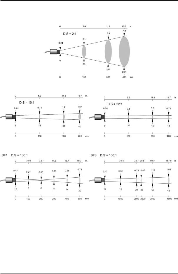
Optical Resolution D:S1 |
|
LTS |
2:1, 10:1, 22:1 typ. (21:1 guaranteed) |
LTF |
10:1 |
LTH |
10:1, 22:1 typ. (21:1 guaranteed) |
G5 |
10:1 |
1M, 2M |
100:1 |
|
SF1 optics: 2 mm spot @ 200 mm distance (0.08 in @ 7.9 in) |
|
SF3 optics: 22 mm spot @ 2200 mm distance (0.87 in @ (8.7 in) |
Response Time2 |
|
LTS (standard), LTH |
130 ms |
LTF (fast) |
20 ms |
G5 |
130 ms |
1M, 2M |
10 ms3 |
Accuracy4 |
|
LT, G5 |
± (1% of reading or 1°C), whichever is greater |
|
± 2°C (± 4°F) for target temp. < 20°C (68°F) |
1M, 2M |
± (0.5% of reading + 2°C) |
Repeatability |
|
LT, G5 |
± 0.5% of reading or ± 0.5°C, whichever is greater |
1M, 2M |
± 0.25% of reading + 1°C |
Temperature Coefficient5 |
|
LT, G5 |
± 0.05 K / K or ± 0.05% of reading / K, whichever is greater |
1M, 2M |
0.01% of reading / K |
1at 90% energy in minimum and distance 400 mm (15.7 in.)
290% response
330 ms – if more than one sensing head drives an analog output of the communication box
4at ambient temperature 23°C ±5°C (73°F ±9°F), ε = 1.0, and calibration geometry
5ambient temperature deviations related to 23°C
MI3 |
Rev. G Nov/2015 |
15 |

Technical Data
3.1.2 Comm Box
Accuracy |
|
mA/V output |
± 1°C |
|
(corresponds to ± 0.015 mA for the current output at 0-20 mA |
|
or ± 0.015 mA for the current output at 4-20 mA |
|
or 4 mV for the voltage output at 0-5 V |
|
or 8 mV for the voltage output at 0-10 V) |
TC output |
± 1.5°C |
Temperature Resolution |
|
mA/V Output |
± 0.1°C (± 0.2°F)1 / 12 bit, for Comm Box (metal) |
mA/V Output |
± 0.02°C (± 0.04°F) / 16 bit, for Comm Box (DIN 6TE, analog) |
Temperature Coefficient |
|
mA/V Output |
± 0.02 K / K |
TC Output |
± 0.05 K / K |
Emissivity |
|
All models |
0.100 to 1.100 |
Transmission |
|
All models |
0.100 to 1.000 |
3.1.2.1 Comm Box (metal) |
|
Loop Time |
|
mA/V Output |
|
LTS, G5 |
8 ms |
LTF, 1M, 2M |
4 ms |
digital |
18 ms * number of connected heads |
3.1.2.2 Comm Box (DIN) |
|
Loop Time |
|
digital |
|
LTS, G5 |
8 ms2 * number of connected heads |
LTF, 1M, 2M |
4 ms3 * number of connected heads |
1for a zoomed temperature span of < 500°C (932°F)
2per bus channel
3per bus channel
16 |
Rev. G Nov/2015 |
MI3 |
Technical Data
3.2 Optical Charts
Figure 1: Spot Size Charts
MI3 |
Rev. G Nov/2015 |
17 |

Technical Data
3.3 Electrical Specification
For an overview to the capabilities of the communication boxes, see section 2.1 Overview Comm Boxes, page 14.
3.3.1 Comm Box, all models
Voltage Supply |
8 to 32 VDC |
Power Consumption |
max. 6 W |
Alarm Output
1 potential-free relay output, 48 V / 300 mA
Relay with wear-free contacts (solid state relay) for target temperature or head ambient temperature, electrically isolated from power supply
USB Interface
Version: 2.0
Connector on the board: type Mini-B
3.3.2 Comm Box (metal)
Analog Outputs |
|
Output 1 |
0 to 5/10 V output for head ambient temperature and object temperature |
|
electrically not isolated from power supply |
Thermocouple |
J: -40 to 600°C (-40 to 1112°F) |
|
K: -40 to 800°C (-40 to 1472°F) |
|
R/S: 250 to 1800°C (482 to 3272°F) |
Output 2 |
0 to 20 mA (active), or |
|
4 to 20 mA (active), or |
|
0 to 5 V, or |
|
0 to 10 V |
|
electrically not isolated from power supply |
External Inputs
3 inputs are available useable in different modes:
FTC1-3 |
Emissivity control: 3 bit digital coded, 0 to VSS |
FTC1 |
Emissivity control: analog, 0 to 5 VDC |
FTC2 |
Ambient temperature compensation analog: 0 to 5 VDC |
FTC3 |
for trigger/hold/laser functions, 0 to VSS |
3.3.3 Comm Box (DIN 6TE, analog) |
|
Analog Outputs |
|
Output 1 to 4 |
0 to 20 mA (active), or |
|
4 to 20 mA (active), or |
|
0 to 5 V, or |
0 to 10 V
Each output is galvanically isolated from the other and from power supply!
18 |
Rev. G Nov/2015 |
MI3 |

Technical Data
3.4 Environmental Specification
3.4.1 Sensing Head
Ambient Temperature |
|
LT, G5 |
-10 to 120°C (14 to 248°F) |
LTH |
-10 to 180°C (14 to 356°F) |
1M, 2M |
0 to 120°C (32 to 248°F) |
Laser (1M, 2M) |
automatic switch off at 65°C (149°F) |
Storage Temperature |
|
LTH |
-20 to 180°C (-4 to 356°F) |
all other models |
-20 to 120°C (-4 to 248°F) |
Rating |
IP65 (NEMA-4) / IEC 60529 |
Relative Humidity |
10% to 95% non-condensing |
EMC |
EN 61326-1:2006 |
KCC |
Electromagnetic Compatibility Applies to use in Korea only. Class A |
|
Equipment (Industrial Broadcasting & Communication Equipment) |
|
This product meets requirements for industrial (Class A) electromagnetic wave equipment and |
|
the seller or user should take notice of it. This equipment is intended for use in business |
|
environments and is not to be used in homes. |
Vibration |
11 to 200 Hz, 3 g above 25 Hz operating, 3 axes / IEC 60068-2-6 |
Shock |
50 g, 11 ms, operating, 3 axes / IEC 60068-2-27 |
Weight |
|
LT, G5 |
50 g (1.8 oz) |
1M, 2M |
233 g (8.2 oz) |
Material |
|
Head |
Stainless steel |
Head Cable |
|
LTH |
Teflon® |
all other models |
PUR (Polyurethane), Halogen free, Silicone free |
Teflon develops poisonous gasses when it comes into contact with flames!
3.4.2 Comm Box (metal)
Ambient Temperature |
-10 to 65°C (14 to 149°F) |
Storage Temperature |
-20 to 85°C (-4 to 185°F) |
Rating |
IP65 (NEMA-4) / IEC 60529 |
Relative Humidity |
10% to 95% non-condensing |
EMC |
EN 61326-1:2006 |
MI3 |
Rev. G Nov/2015 |
19 |

Technical Data
KCC |
Electromagnetic Compatibility Applies to use in Korea only. Class A |
|
Equipment (Industrial Broadcasting & Communication Equipment) |
|
This product meets requirements for industrial (Class A) electromagnetic |
|
wave equipment and the seller or user should take notice of it. This |
|
equipment is intended for use in business environments and is not to be |
|
used in homes. |
Vibration |
11 to 200 Hz, 3 g above 25 Hz operating, 3 axes / IEC 60068-2-6 |
Shock |
50 g, 11 ms, operating, 3 axes / IEC 60068-2-27 |
Weight |
370 g (13 oz) |
Material |
die-cast zinc enclosure |
3.4.3 Comm Box (DIN)
Ambient Temperature |
-10 to 65°C (14 to 149°F) |
Storage Temperature |
-20 to 85°C (-4 to 185°F) |
Relative Humidity |
10% to 95% non-condensing |
EMC |
EN 61326-1:2006 |
KCC |
Electromagnetic Compatibility Applies to use in Korea only. Class A |
|
Equipment (Industrial Broadcasting & Communication Equipment) |
|
This product meets requirements for industrial (Class A) electromagnetic |
|
wave equipment and the seller or user should take notice of it. This |
|
equipment is intended for use in business environments and is not to be |
|
used in homes. |
Vibration |
11 to 200 Hz, 3 g above 25 Hz operating, 3 axes / IEC 60068-2-6 |
Shock |
50 g, 11 ms, operating, 3 axes / IEC 60068-2-27 |
Weight |
125 g (4.4 oz) |
Material |
molded plastic |
3.4.4 LTH Electronics
Ambient Temperature |
-10 to 65°C (14 to 149°F) |
Storage Temperature |
-20 to 85°C (-4 to 185°F) |
Rating |
IP65 (NEMA-4) / IEC 60529 |
20 |
Rev. G Nov/2015 |
MI3 |
Technical Data
3.5 Dimensions
3.5.1 Sensing Head LT, G5
Standard cable length 1 m (3 ft.)
Ø 5 mm (0.2 in)
Figure 2: Dimensions of LT, G5 Sensing Heads
3.5.2 Sensing Head LTH
Figure 3: Dimensions of LTH Sensing Head with separated Electronics
3.5.3 Sensing Head 1M, 2M
Standard cable length 1 m (3 ft)
Ø 5 mm (0.2 in)
Figure 4: Dimensions of 1M, 2M Sensing Heads
3.5.4 Comm Box (metal)
The box is equipped with three cable feed-through ports – two with IP65 compatible sealing glands, a third sealing gland comes for boxes with fieldbus communications (RS485, Profibus etc.). Boxes without fieldbus have a plugged expansion feed-through port instead (M12x1.5 thread).
MI3 |
Rev. G Nov/2015 |
21 |

Technical Data
Figure 5: Dimensions of Communication Box
3.5.5 Comm Box (DIN)
The boxes come in a standard DIN rail size in accordance to EN 50022-35x7.5 (DIN 43880).
|
|
|
|
Width |
MI3MCOMMN |
MI3MCOMM |
MI3MCOMM… |
X |
DIN 3TE: |
DIN 4TE: |
DIN 6TE: |
|
53.6 mm (2.1 in) |
71.6 mm (2.8 in) |
107.6 mm (4.2 in) |
|
|
|
|
Figure 6: Dimensions for Comm Boxes (DIN)
3.6 Scope of Delivery
3.6.1 Sensing Head
Sensing head with cable
Integrated Laser (1M, 2M heads only)
Mounting nut
22 |
Rev. G Nov/2015 |
MI3 |

Technical Data
3.6.2 Comm Box
Communication box
for Comm Box (DIN) only - XXXMI3MCOMMSET: ferrite cores (4 pcs), shield tapes (4 pcs)
Software DVD
Quickstart guide
MI3 |
Rev. G Nov/2015 |
23 |

Basics
4 Basics
4.1 Measurement of Infrared Temperature
All surfaces emit infrared radiation. The intensity of this infrared radiation changes according to the temperature of the object. Depending on the material and surface properties, the emitted radiation lies in a wavelength spectrum of approximately 1 to 20 µm. The intensity of the infrared radiation (heat radiation) is dependent on the material. For many substances, this material-dependent constant is known. This constant is referred to as the ”emissivity value”.
Infrared thermometers are optical-electronic sensors. These sensors are sensitive to the emitted radiation. Infrared thermometers are made up of a lens, a spectral filter, a sensor, and an electronic signal processing unit. The task of the spectral filter is to select the wavelength spectrum of interest. The sensor converts the infrared radiation into an electrical signal. The signal processing electronics analyze the electrical signal and convert it into a temperature measurement. As the intensity of the emitted infrared radiation is dependent on the material, the required emissivity can be selected on the sensor.
The biggest advantage of the infrared thermometer is its ability to measure temperature without touching an object. Consequently, surface temperatures of moving or hard to reach objects can easily be measured.
4.2 Emissivity of Target Object
To determine the emissivity of the target object see section 19.1 Determination of Emissivity, page 128. If emissivity is low, measured results could be falsified by interfering infrared radiation from background objects (such as heating systems, flames, fireclay bricks, etc. located close beside or behind the target object). This type of problem can occur when measuring reflective surfaces and very thin materials, such as plastic film and glass.
This measurement error can be reduced to a minimum, if particular care is taken during installation and the sensing head is shielded from these reflecting radiation sources.
4.3 Ambient Temperature
The sensing head is suited for the ambient temperatures up to 120°C (248°F) for the standard heads and up to 180°C (356°F) for the LTH heads. The sensing head can operate in ambient temperatures up to 200°C (392°F) with the air-cooling accessory.
4.4 Atmospheric Quality
If the lens gets dirty, infrared energy will be blocked and the instrument will not measure accurately. It is good practice to always keep the lens clean. The Air Purge Jacket helps keep contaminants from building up on the lens. If you use air purging, make sure a filtered air supply with clean dry air at the correct air pressure is installed before proceeding with the sensor installation.
4.5 Electrical Interference
To minimize electrical or electromagnetic interference or “noise”, please be aware of the following:
Mount the unit as far away as possible from potential sources of electrical interference, such as motorized equipment, which can produce large step load changes.
Use shielded wire for all input and output connections.
To avoid current equalizations, make sure that a sufficient potential equalization is realized between the sensing head and metal housing of the communication box.
24 |
Rev. G Nov/2015 |
MI3 |
Basics
To avoid ground loops, make sure that only one point is earth grounded, either via the sensing head, the Comm Box, or power.
Please note that:
The metal housings of the sensing head and the MI3 communication box are electrically connected to the shield of the head cable.
All inputs and outputs (except the alarm output and the outputs of the Comm Box (DIN 6TE, analog)) use the same ground and are electrically connected to the power supply.
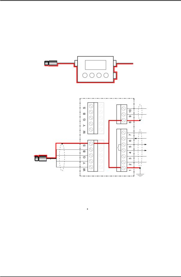
Figure 7: Shield Run for Comm Box (metal)
Figure 8: Shield Run for Comm Box (DIN)
|
Head |
|
Box |
|
Power |
|
|||||||
|
|
Shield |
|
|
|
|
|
|
|
|
Shield |
|
|
|
|
|
|
|
|
|
|
|
|
|
|
||
|
|
|
|
|
|
|
|
|
|
|
|
|
|
|
|
|
|
|
|
|
|
|
|
|
|
|
|
|
|
|
|
|
|
|
|
|
|
|
|
|
|
|
|
|
|
|
|
|
|
|
|
|
|
|
|
|
|
|
|
|
|
|
|
|
|
|
|
|
|
|
|
|
|
|
|
|
|
|
|
|
|
|
|
Figure 9: Only one point is earth grounded either via sensing head, via Comm Box, or via Power
MI3 |
Rev. G Nov/2015 |
25 |
Installation
5 Installation
5.1 Positioning
Sensor location depends on the application. Before deciding on a location, you need to be aware of the ambient temperature of the location, the atmospheric quality of the location, and the possible electromagnetic interference in that location. If you plan to use air purging, you need to have an air connection available. Wiring and conduit runs must be considered, including computer wiring and connections, if used.
5.1.1 Distance to Object
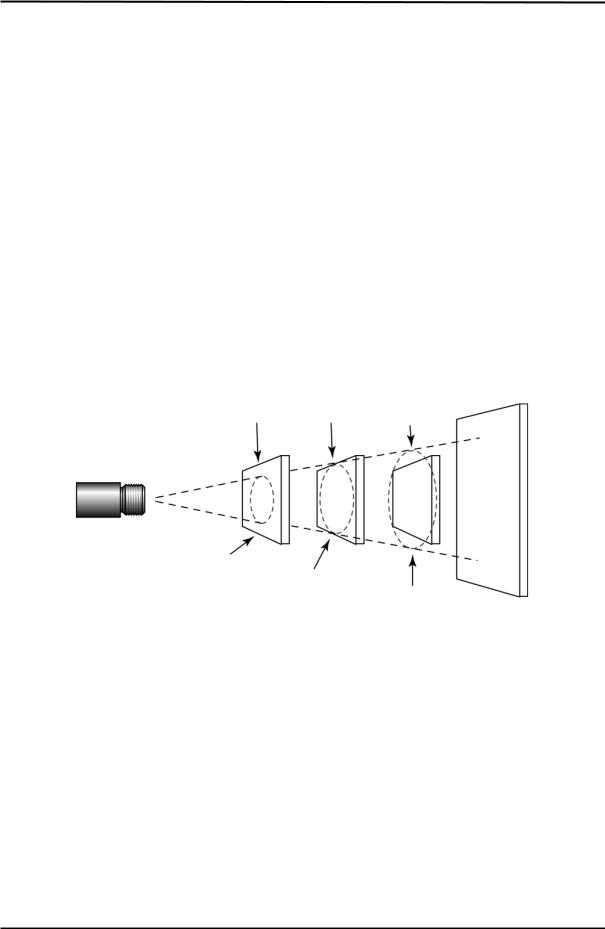
The desired spot size on the target will determine the maximum measurement distance. To avoid erroneous readings, the target spot size must completely fill the entire field of view of the sensor. Consequently, the sensor must be positioned so the field of view is the same as or smaller than the desired target size. For a list indicating the available optics, see section 3.2 Optical Charts, page 17.
The actual spot size for any distance can be calculated by using the following formula. Divide the distance D by your model’s D:S number. For example, for a unit with D:S = 10:1, if the sensor is
400 mm (15.7 in.) from the target, divide 400 by 10 (15.7 by 10), which gives you a target spot size of approximately 40 mm (1.57 in.).
best |
critical |
incorrect |
Sensor
Background
Target greater than spot size
Target equal to spot
Targets smaller than spot size
Figure 10: Proper Sensor Placement
5.2 Installation Schemes
5.2.1 Comm Box (metal)
The basic stand-alone configuration consists of one sensing head interfaced to one metallic communications box. The sensing head provides all IR measurement functionality. The communications box provides an externally accessibly user interface and display, advanced signal processing capability, field wiring terminations and fieldbus functionality with optional RS485 communication interface.
26 |
Rev. G Nov/2015 |
MI3 |
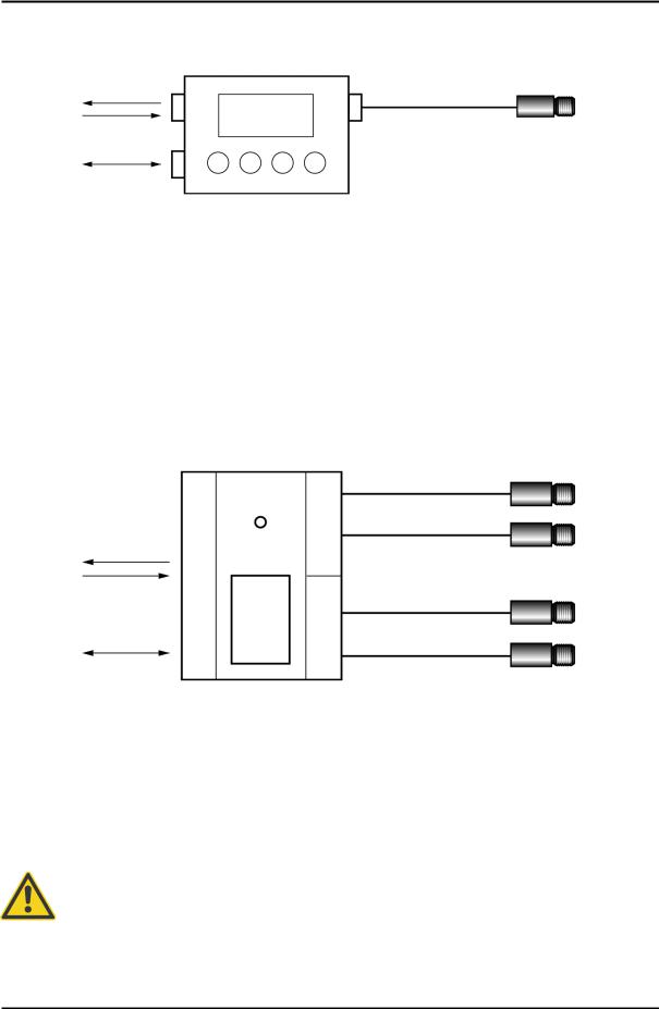
|
|
Installation |
Power supply, |
Comm Box |
|
2 analog |
(RAYMI3COMM) |
Head 1 |
outputs, |
|
(RAYMI3…) |
3 inputs |
|
|
Fieldbus |
|
|
Figure 11: Single Head Configuration with Comm Box
To increase the number of supported sensing heads, you can use a dedicated accessory, see section 10.1.1 Multi-Channel Box, page 64.
5.2.2 Comm Box (DIN)
The multiple sensing head configuration consists of a modular communication box provided in a DIN rail mountable plastic enclosure for supporting 4 sensing heads simultaneously. The DIN rail communication box provides an externally accessibly user interface. The terminal strip connectors are
used to simplify the field wiring.
Power supply 1 alarm output, 1 trigger input
Fieldbus or
4x analog
DIN Rail Comm Box
(RAYMI3MCOMM)
Total length: |
max. 30 m (98 ft) |
Total length: |
max. 30 m (98 ft) |
Max. 8 Sensing Heads
(RAYMI3…)
Figure 12: Multiple Head Configuration with DIN Rail Comm Box
5.3 Wiring, Head Cable
The user has to install the sensor cable on the communication box. It may be shortened, if necessary, but keep a minimal length of 20 cm (7.9 in).
Do not bend the sensing head cable tighter than a radius of 25 mm (1 in.) for the standard heads (PUR cable) and 15 mm (0.6 in.) for the high ambient temperature heads (Teflon cable) respectively!
To prevent possible fluctuating temperature readings or damages to the device make sure that the sensor head is grounded before use!
MI3 |
Rev. G Nov/2015 |
27 |

Installation
The total sensing head cable length for all networked sensing heads must not exceed 30 m (98 ft) for MI3 and 2x30 m (2x98 ft) for MI3M!
Do not add a third party cable to extend the length of the sensing head cable!
5.3.1Comm Box (metal)
1.Cut about 40 mm (1.5 in) of the cable sheath from the end of the sensing head cable . Caution: Do not cut into the shield!
2.Cut the shield so about 5 mm (0.2 in) remains exposed from under the cable sheath. Separate the shield and spread the strands out.
3.Strip 3 mm (0.12 in) of insulation from the wires !
4.Open the communication box by removing the four Phillips head screws and pulling off the
lid. Unscrew the pressure screw , and remove the first metal washer , the rubber washer , and the second and the third metal washers .
5.Put the following on the cable: the pressure screw , the first metal washer , the rubber washer and the second metal washers , see the following figure.
6.Spread the cable shield and then slip the third metal washer onto the cable. Note that the shield must make good contact to both metal washers.
7.Slip the wires into the communication box far enough to connect to the terminal.
8.Screw the pressure screw into the communication box. Tighten snuggly. Do not over tighten.
9.Connect the wires to the terminal on the printed circuit board.
Cable and sensing head
Figure 13: Sensing Head Cable to the Comm Box
28 |
Rev. G Nov/2015 |
MI3 |
Installation
5.3.2 Comm Box (DIN)
The wiring of the sensing head cable is color coded, see section 5.4.3 Comm Box (DIN 4 TE), page 31.
5.4 Wiring, Terminal
You need to connect the power supply and possibly the signal input/output wires. Use only cable with outside diameter from 4 to 6 mm (0.16 to 0.24 in), wire size: 0.14 to 0.75 mm² (AWG 19 to 26).
The cable must include shielded wires. It should not be used as a strain relief!
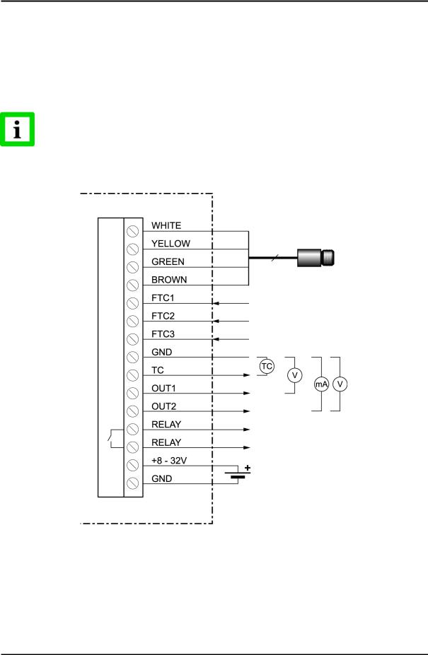
5.4.1 Comm Box (metal)
Sensing Head
Emissivity Control
Ambient Compensation
Trigger/Hold
Tobj Thead Tobj/Thead
Alarm: Tobj / Thead
Power Supply
Figure 14: Terminal Wiring for the Comm Box
MI3 |
Rev. G Nov/2015 |
29 |
Installation
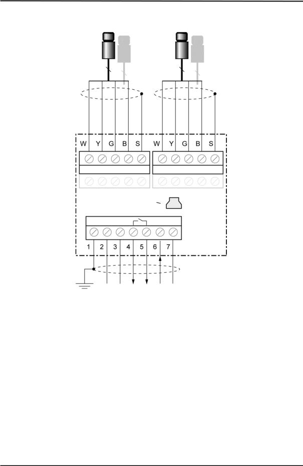
5.4.2 Comm Box (DIN 3TE)
Sensing
Heads
white |
yellow |
green |
brown |
shield |
white |
yellow |
green |
brown |
shield |
USB Connector, Mini-B
Shield |
GND |
V 32 - 8 |
RELAY |
RELAY |
FTC3 |
GND |
Figure 15: Terminal Wiring for the Comm Box DIN 3TE
30 |
Rev. G Nov/2015 |
MI3 |
 Loading...