

Page 1

MARATHON
MR
2-Color Infrared Thermometer
Operating Instructions
Rev. E2 04/2011
56913
Page 2

Page 3

Contacts
Raytek Corporation
Worldwide Headquarters
Santa Cruz, CA USA
Tel: +1 800 227 – 8074 (USA and Canada only)
+1 831 458 – 3900
solutions@raytek.com
European Headquarters
Berlin, Germany
Tel: +49 30 4 78 00 80
raytek@raytek.de
France
info@raytek.fr
United Kingdom
ukinfo@raytek.com
China Headquarters
Beijing, China
Tel: +86 10 6438 4691
info@raytek.com.cn
Internet: http://www.raytek.com/
Thank you for purchasing this Raytek product. Register today at www.raytek.com/register to receive
the latest updates, enhancements and software upgrades!
© Raytek Corporation.
Raytek, DataTemp and the Raytek Logo are registered trademarks of Raytek Corporation.
All rights reserved. Specifications subject to change without notice.
Page 4

WARRANTY
The manufacturer warrants this instrument to be free from defects in material and workmanship
under normal use and service for the period of two years from date of purchase. This warranty
extends only to the original purchaser. This warranty shall not apply to fuses, batteries, or any
product that has been subject to misuse, neglect, accident, or abnormal conditions of operation.
In the event of failure of a product covered by this warranty, the manufacturer will repair the
instrument when it is returned by the purchaser, freight prepaid, to an authorized Service Facility
within the applicable warranty period, provided manufacturer’s examination discloses to its
satisfaction that the product was defective. The manufacturer may, at its option, replace the product in
lieu of repair. With regard to any covered product returned within the applicable warranty period,
repairs or replacement will be made without charge and with return freight paid by the manufacturer,
unless the failure was caused by misuse, neglect, accident, or abnormal conditions of operation or
storage, in which case repairs will be billed at a reasonable cost. In such a case, an estimate will be
submitted before work is started, if requested.
THE FOREGOING WARRANTY IS IN LIEU OF ALL OTHER WARRANTIES, EXPRESSED OR
IMPLIED, INCLUDING BUT NOT LIMITED TO ANY IMPLIED WARRANTY OF
MERCHANTABILITY, FITNESS, OR ADEQUACY FOR ANY PARTICULAR PURPOSE OR USE.
THE MANUFACTURER SHALL NOT BE LIABLE FOR ANY SPECIAL, INCIDENTAL OR
CONSEQUENTIAL DAMAGES, WHETHER IN CONTRACT, TORT, OR OTHERWISE.
SOFTWARE WARRANTY
The manufacturer does not warrant that the software described herein will function properly in every
hardware and software environment. This software may not work in combination with modified or
emulated versions of Windows operating environments, memory-resident software, or on computers
with inadequate memory. The manufacturer warrants that the program disk is free from defects in
material and workmanship, assuming normal use, for a period of one year. Except for this warranty,
the manufacturer makes no warranty or representation, either expressed or implied, with respect to
this software or documentation, including its quality, performance, merchantability, or fitness for a
particular purpose. As a result, this software and documentation are licensed “as is,” and the licensee
(i.e., the User) assumes the entire risk as to its quality and performance. The liability of the
manufacturer under this warranty shall be limited to the amount paid by the User. In no event shall
the manufacturer be liable for any costs including but not limited to those incurred as a result of lost
profits or revenue, loss of use of the computer software, loss of data, the cost of substitute software,
claims by third parties, or for other similar costs. The manufacturer’s software and documentation are
copyrighted with all rights reserved. It is illegal to make copies for another person.
Specifications subject to change without notice.
The device complies with the requirements of the European Directives.
EC – Directive 2004/108/EC (EMC)
Page 5

TABLE OF CONTENTS
1 SAFETY INSTRUCTIONS .............................................................................................................................. 7
2 PRODUCT DESCRIPTION ............................................................................................................................ 8
2.1 THEORY OF OPERATION FOR 2-COLOR SENSORS ......................................................................................... 9
2.1.1 Partially Obscured Targets ................................................................................................................... 9
2.1.2 Targets Smaller Than Field of View ...................................................................................................... 9
2.1.3 Low or Changing Emissivities ............................................................................................................ 10
3 TECHNICAL DATA ....................................................................................................................................... 11
3.1 MEASUREMENT SPECIFICATIONS ............................................................................................................... 11
3.2 GENERAL SPECIFICATIONS ......................................................................................................................... 13
3.3 ELECTRICAL SPECIFICATIONS ..................................................................................................................... 14
3.4 DIMENSIONS ............................................................................................................................................... 14
3.5 OPTICAL SPECIFICATIONS .......................................................................................................................... 16
3.6 SCOPE OF DELIVERY .................................................................................................................................... 17
4 ENVIRONMENT ............................................................................................................................................ 18
4.1 AMBIENT TEMPERATURE ............................................................................................................................ 18
4.2 ATMOSPHERIC QUALITY ............................................................................................................................. 18
4.3 ELECTRICAL INTERFERENCE ....................................................................................................................... 18
5 INSTALLATION ............................................................................................................................................ 19
5.1 MECHANICAL INSTALLATION .................................................................................................................... 19
5.1.1 Distance to Object ............................................................................................................................... 19
5.1.2 Sensor Placement (1-Color Mode) ...................................................................................................... 19
5.1.3 Sensor Placement (2-Color Mode) ...................................................................................................... 20
5.1.4 Viewing Angles ................................................................................................................................... 21
5.1.5 Aiming and Focusing .......................................................................................................................... 22
5.2 ELECTRICAL INSTALLATION ....................................................................................................................... 23
5.2.1 DIN Connector Wiring ....................................................................................................................... 23
5.2.2 Cables and Terminal Block .................................................................................................................. 23
5.2.3 Power Supply ...................................................................................................................................... 25
5.2.4 PC Connection via USB/RS485 Converter ......................................................................................... 26
5.2.5 PC Connection via RS232/485 Converter .......................................................................................... 27
5.2.6 Addressing .......................................................................................................................................... 29
6 OPERATION ................................................................................................................................................... 30
6.1 CONTROL PANEL ........................................................................................................................................ 30
6.2 OPERATION MODES .................................................................................................................................... 31
6.2.1 Temperature Display ........................................................................................................................... 31
6.2.2 Emissivity (1-Color) ............................................................................................................................ 31
6.2.3 Slope (2-Color) .................................................................................................................................... 32
6.2.4 2C/1C Switch ...................................................................................................................................... 32
6.2.5 Overview to Hold Functions ............................................................................................................... 34
6.2.6 Setpoints .............................................................................................................................................. 35
6.2.7 Deadband............................................................................................................................................. 35
Page 6

6.3 INPUTS AND OUTPUTS ............................................................................................................................... 36
6.3.1 Milliamp Output ................................................................................................................................ 36
6.3.2 Relay Outputs .................................................................................................................................... 36
6.3.3 Trigger ................................................................................................................................................ 36
6.4 FACTORY DEFAULTS .................................................................................................................................. 37
7 OPTIONS ......................................................................................................................................................... 38
7.1 WATER COOLED HOUSING INCLUDING AIR PURGE COLLAR .................................................................. 38
8 ACCESSORIES ............................................................................................................................................... 39
8.1 OVERVIEW .................................................................................................................................................. 39
8.2 FIXED MOUNTING BRACKET ...................................................................................................................... 39
8.3 AIR PURGE COLLAR ................................................................................................................................... 40
8.4 POLARIZING FILTER END CUP ................................................................................................................... 40
8.5 CABLES ....................................................................................................................................................... 41
8.6 INDUSTRIAL POWER SUPPLY ...................................................................................................................... 43
9 PROGRAMMING GUIDE ........................................................................................................................... 44
9.1 REMOTE VERSUS MANUAL CONSIDERATIONS .......................................................................................... 44
9.2 COMMAND STRUCTURE ............................................................................................................................. 44
9.3 TRANSFER MODES ...................................................................................................................................... 45
9.3.1 Poll Mode ............................................................................................................................................ 45
9.3.2 Burst Mode ......................................................................................................................................... 45
9.4 RESPONSE TIME IN SETUP MODE ............................................................................................................... 46
9.5 COMMAND LIST ......................................................................................................................................... 47
9.6 COMMAND EXAMPLES ............................................................................................................................... 49
10 MAINTENANCE .......................................................................................................................................... 50
10.1 TROUBLESHOOTING MINOR PROBLEMS .................................................................................................. 50
10.2 FAIL-SAFE OPERATION ............................................................................................................................ 50
10.3 CLEANING THE LENS ............................................................................................................................... 53
10.4 CHANGING THE WINDOW ....................................................................................................................... 53
11 APPENDIX..................................................................................................................................................... 54
11.1 DETERMINATION OF EMISSIVITY .............................................................................................................. 54
11.2 TYPICAL EMISSIVITY VALUES ................................................................................................................... 54
11.3 TYPICAL SLOPES ....................................................................................................................................... 56
11.4 2-WIRE COMMUNICATION ....................................................................................................................... 57
11.5 TRACEABILITY OF INSTRUMENT CALIBRATION ....................................................................................... 58
Page 7
Safety Instructions
Marathon MR Rev. E2 04/2011 7
1
This document contains important information, which should be kept at all times with the instrument
during its operational life. Other users of this instrument should be given these instructions with the
instrument. Eventual updates to this information must be added to the original document. The
instrument can only be operated by trained personnel in accordance with these instructions and local
safety regulations.
Acceptable Operation
This instrument is intended only for the measurement of temperature. The instrument is appropriate
for continuous use. The instrument operates reliably in demanding conditions, such as in high
environmental temperatures, as long as the documented technical specifications for all instrument
components are adhered to. Compliance with the operating instructions is necessary to ensure the
expected results.
Unacceptable Operation
The instrument should not be used for medical diagnosis.
Replacement Parts and Accessories
Use only original parts and accessories approved by the manufacturer. The use of other products can
compromise the operation safety and functionality of the instrument.
Instrument Disposal
Do not dispose of this product as unsorted municipal waste. Go to Fluke’s website for
recycling information.
Operating Instructions
The following symbols are used to highlight essential safety information in the operation instructions:
Helpful information regarding the optimal use of the instrument.
Risk of danger. Important information!
Incorrect use of 110 / 230 V electrical systems can result in electrical hazards and personal
injury. All instrument parts supplied with electricity must be covered to prevent physical
contact and other hazards at all times.
Page 8
Product Description
8 Rev. E2 04/2011 Marathon MR
2
The Marathon MR Series of instruments are 2-color infrared noncontact temperature measurement
systems with variable focus, through-the-lens sighting, and parallax-free optics. They are energy
transducers designed to measure accurately and repeatedly the amount of heat energy emitted from
an object, and then convert that energy into a measurable electrical signal. Temperature measurements
can be taken using either of the following modes:
1-color mode – for standard temperature measurements. The 1-color mode is best for
measuring the temperature of targets in areas where no sighting obstructions, either solid or
gaseous, exist. The 1-color mode is also best where the target completely fills the measurement
spot and where the background or foreground are higher in temperature than the target.
2-color mode – temperatures are determined from the ratio of two separate and overlapping
infrared bands. The 2-color mode is best for measuring the temperature of targets that are
partially obscured (either intermittently or permanently) by other objects, openings, screens, or
viewing windows that reduce energy, and by dirt, smoke, or steam in the atmosphere. The 2color mode can also be used on targets that do not completely fill the measurement spot,
provided the background is much cooler than the target.
Each model operates as an integrated temperature measurement subsystem consisting of optical
elements, spectral filters, detector, digital electronics and a NEMA-4 (IEC 529, IP65) housing. Each is
built to operate on a 100 percent duty cycle in industrial environments. Outputs consist of
standardized current signals commonly available for use with computers, controllers, recorders,
alarms, or A/D interfaces.
Model
Temperature Range
Minimum Temperature
(95% Attenuation)
Optical Resolution
(Nominal)
Standard Focus
MR1SASF
MR1SBSF
MR1SCSF
600 to 1400°C (1112 to 2552°F)
700 to 1800°C (1292 to 3272°F)
1000 to 3000°C (1832 to 5432°F)
800°C (1472°F)
950°C (1742°F)
1300°C (2372°F)
44:1
82:1
130:1
Close Focus
MR1SACF
MR1SBCF
MR1SCCF
600 to 1400°C (1112 to 2552°F)
700 to 1800°C (1292 to 3272°F)
1000 to 3000°C (1832 to 5432°F)
800°C (1472°F)
950°C (1742°F)
1300°C (2372°F)
44:1
82:1
130:1
Focal Range SF = Standard Focus 600 mm to ∞ (24" to ∞)
CF = Close Focus 300 mm to 600 mm (12" to 24")
Table 1: Models
All Marathon sensors are addressable and can be used in multidrop environments. Setup, utility, and
operating/monitoring software is included with your sensor(s).
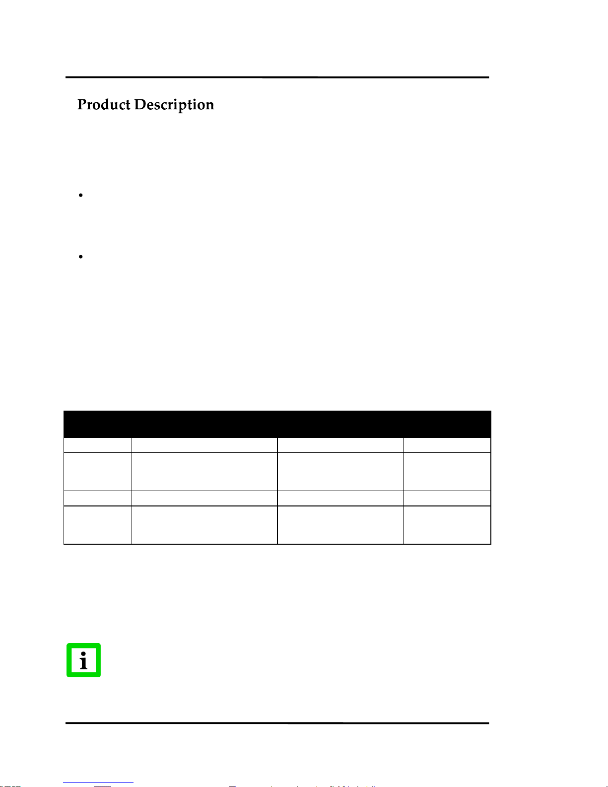
For the percentage of allowed signal reduction at temperatures below the minimum
temperature (95% attenuation) as shown above, refer to Figure 1.
Page 9

Product Description
Marathon MR Rev. E2 04/2011 9
2.1 Theory of Operation for 2-Color Sensors
Two-color ratio technology makes possible accurate and repeatable temperature measurements that
are free from dependence on absolute radiated energy values. In use, a 2-color sensor determines
temperature from the ratio of the radiated energies in two separate wavelength bands (colors).
The benefits of 2-color sensors are that accurate measurements can be made under the following
conditions:
When the field of view to the target is partially blocked or obscured.
When the target is smaller than the sensor’s field of view.
When target emissivities are low or changing by the same factor in both wavelength bands.
Another benefit is that 2-color sensors measure closer to the highest temperature within the measured
spot (spatial peak picking) instead of an average temperature. A 2-color sensor can be mounted farther
away, even if the target does not fill the resulting spot size. The convenience is that you are not forced
to install the sensor at some specific distance based upon target size and the sensor’s optical
resolution.
2.1.1 Partially Obscured Targets
The radiated energy from a target is, in most cases, equally reduced when objects or atmospheric
materials block some portion of the optical field of view. It follows that the ratio of the energies is
unaffected, and thus the measured temperatures remain accurate. A 2-color sensor is better than a
1-color sensor in the following conditions:
Sighting paths are partially blocked (either intermittently or permanently).
Dirt, smoke, or steam is in the atmosphere between the sensor and target.
Measurements are made through items or areas that reduce emitted energy, such as grills,
screens, small openings, or channels.
Measurements are made through a viewing window that has unpredictable and changing
infrared transmission due to accumulating dirt and/or moisture on the window surface.
The sensor itself is subject to dirt and/or moisture accumulating on the lens surface.
1-color sensors see polluted atmosphere and dirty windows and lenses as a reduction in
energy and give much lower than actual temperature readings!
2.1.2 Targets Smaller Than Field of View
When a target is not large enough to fill the field of view, or if the target is moving within the field of
view, radiated energies are equally reduced, but the ratio of the energies is unaffected and measured
temperatures remain accurate. This remains true as long as the background temperature is much
lower than the target’s. The following examples show where 2-color sensors can be used when targets
are smaller than the field of view:
Measuring wire or rod — often too narrow for field of view or moving or vibrating
unpredictably. It is much easier to obtain accurate results because sighting is less critical with
two-color sensors.
Measuring molten glass streams — often narrow and difficult to sight consistently with
single-wavelength sensors.
Page 10

Product Description
10 Rev. E2 04/2011 Marathon MR
2.1.3 Low or Changing Emissivities
If the emissivities in both wavelengths (colors) were the same, as they would be for any blackbody
(emissivity = 1.0) or greybody (emissivity < 1.0 but constant), then their ratio would be 1, and target
emissivity would not be an influence. However, in nature there is no such thing as a greybody. The
emissivity of all real objects changes with wavelength and temperature, at varying degrees, depending
on the material.
When emissivity is uncertain or changing, a 2-color sensor can be more accurate than a 1-color
instrument as long as the emissivity changes by the same factor in both wavelength bands. Note,
however, that accurate measurement results are dependent on the application and the type of material
being measured. To determine how to use 2-color sensors with your application when uncertain or
changing emissivities are a factor, please contact your sales representative.
Page 11

Technical Data
Marathon MR Rev. E2 04/2011 11
3
3.1 Measurement Specifications
Temperature Range
MR1SA 600 to 1400°C (1112°F to 2552°F)
MR1SB 700 to 1800°C (1292°F to 3272°F)
MR1SC 1000 to 3000°C (1832°F to 5432°F)
Spectral Nominal Response 1.0 µm nominal (Si/Si layered detector)
Spectral Band Response
1-color band 0.75 to 1.1 μm
2-color band 0.75 to 1.1 μm, 0.95 to 1.1 μm
System Accuracy ±(0.5% Tmeas + 2°C), Tmeas in °C
with no attenuation
Repeatability ±0.3% full scale
Temperature Resolution ±1°C (±2°F) for display and RS485 interface
Analog Output Resolution
MR1SA, MR1SB 1°C or 1°F
MR1SC 1°C or 2°F
Response Time (95% Response) all models 10 ms for signal to reach 95% of final temperature
Temperature Coefficient All models 0.03% full scale change per 1°C change in ambient
temperature
Emissivity (1-color) 0.10 to 1.00, digitally adjustable in increments of 0.01
Slope (2-color) 0.850 to 1.150, digitally adjustable in increments of 0.001
Signal Processing Peak hold, averaging
Noise Equivalent Temperature all models 1°C peak to peak, target emissivity of 1.00,
(NET) unobscured target
3°C peak to peak, for all specified attenuation conditions
Peak Hold Range 0.1 to 299.9 s (300 s = )
Averaging Range 0.1 to 299.9 s (300 s = )
Warm Up Period 15 minutes
Figure 1, Figure 2, and Figure 3 show each sensor model’s percentage of allowed signal reduction at
all temperatures. Refer to these graphs to estimate what percentage of target area must be visible to
the sensor at temperatures below the minimum temperature (95% attenuation) as shown in Table 1.
Page 12
Technical Data
12 Rev. E2 04/2011 Marathon MR
Figure 1: Model A Percentage of Allowed Signal Reduction
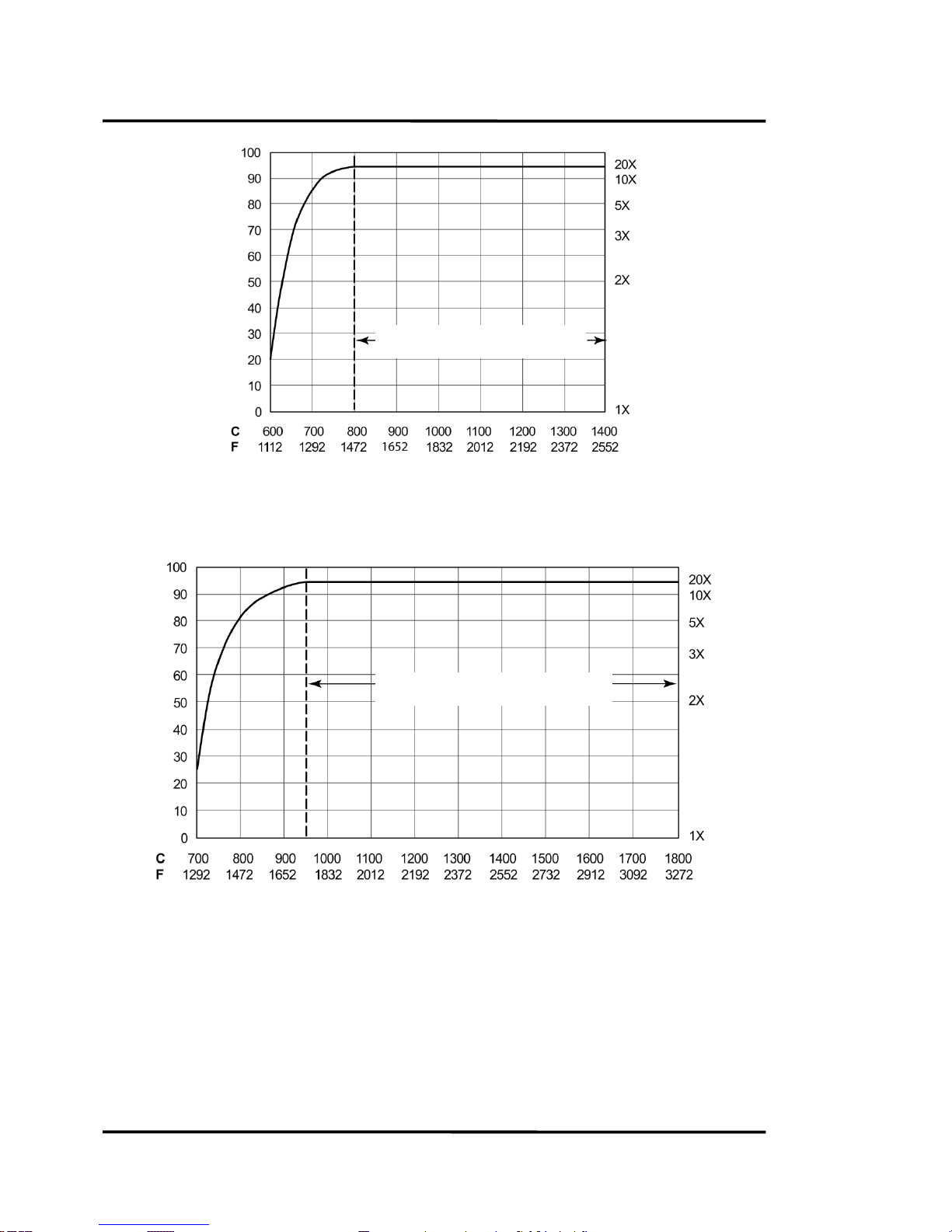
Figure 2: Model B Percentage of Allowed Signal Reduction
Model A – up to 95% allowed signal reduction
800°C (1472°F) to 1400°C (2552°F)
Attenuation Factor
Target Temperature
Maximum Allowed Signal Reduction [%]
Model B – up to 95% allowed signal reduction
950°C (1742°F) to 1800°C (3272°F)
Attenuation Factor
Target Temperature
Maximum Allowed Signal Reduction [%]
Page 13
Technical Data
Marathon MR Rev. E2 04/2011 13
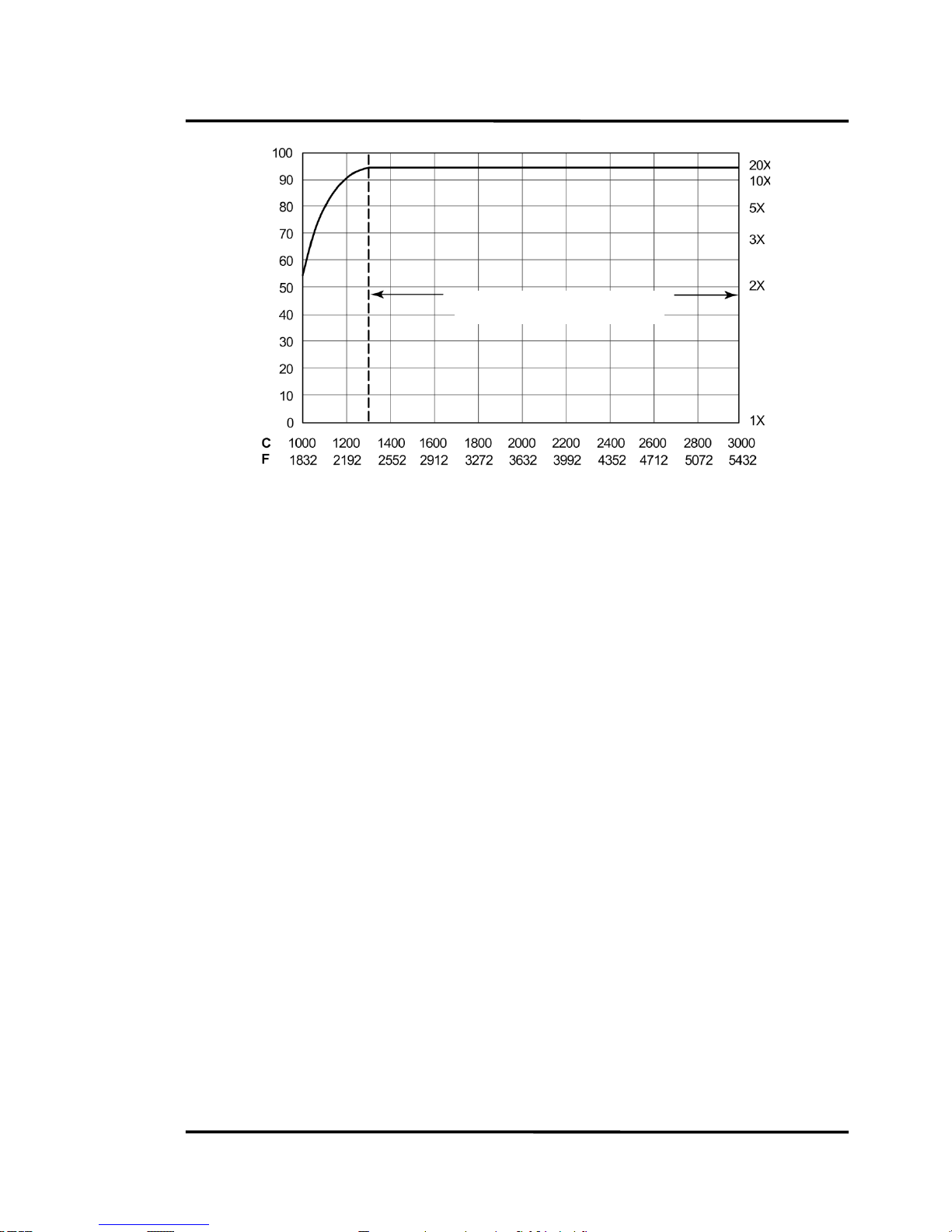
Figure 3: Model C Percentage of Allowed Signal Reduction
3.2 General Specifications
Display 7-segment LED display—shows temperature, slope, emissivity,
peak hold seconds, average seconds, and failsafe codes.
Individual LED’s indicate modes and active functions (e.g.,
2C/1C mode, slope, emissivity, peak hold, and average)
Environmental Rating IP65 (IEC 529, NEMA-4)
Ambient Temperature
without cooling 0 to 50°C (32°F to 122°F)
with air cooling 0 to 120°C (32°F to 250°F)
with water cooling 0 to 175°C (32°F to 350°F)
with ThermoJacket 0 to 315°C (32°F to 600°F)
Storage Temperature
Electronics Housing -20 to 70°C (-4°F to 158°F)
Relative Humidity 10 to 95%, not condensing at 22°C to 43°C (72°F to 110°F)
Electromagnetic Interference CE Emission Standard: EN50081-2
CE Immunity Standard: EN50082-2
Mechanical Shock
Electronics Housing MIL-STD-810D (IEC 68-2-27), 50 G, 11 msec duration, 3 axis
Vibrations
Electronics Housing MIL-STD-810D (IEC 68-2-6), 3 G, 11 to 200 Hz 3 axis
Thermal Shock none
Warm up Period 15 minutes
Weight
sensor 480 g (17 oz)
Attenuation Factor
Target Temperature
Maximum Allowed Signal Reduction [%]
Model C – up to 95% allowed signal reduction
1300°C (2372°F) to 3000°C (5432°F)
Page 14
Technical Data
14 Rev. E2 04/2011 Marathon MR
with air/water-cooled housing 800 g (28 oz)
Fail-Safe Full or low scale, depending upon system failure, see section
10.2 Fail-Safe Operation, Seite 50.
3.3 Electrical Specifications
Power Supply 24 VDC ±20%, 500 mA (max 100 mV peak to peak of ripple)
Power Consumption max. 12 W
Outputs
Analog 0 - 20 mA, 4 - 20 mA, active output, 16 bit resolution
max current loop impedance: 500 Ω
Digital RS485 networkable to 32 sensors
Baud rate: 300, 1200, 2400, 9600, 19200, 38400 (default)
Data format: 8 bit, no parity, 1 stop bit,
Software selectable 4-wire, full-duplex non-multidrop, point-topoint or 2-wire half duplex multidrop
Relay Contacts max. 48 V, 300 mA, response time < 2 ms, (software
programmable)
Relay Contacts Type: SPDT contact closure
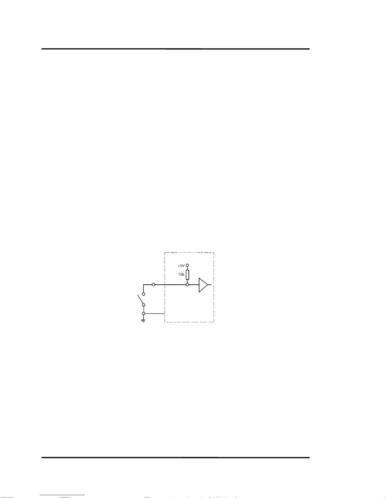
Input
External Reset TTL input, trigger for resetting peak hold
Figure 4: External Reset Wiring Diagram
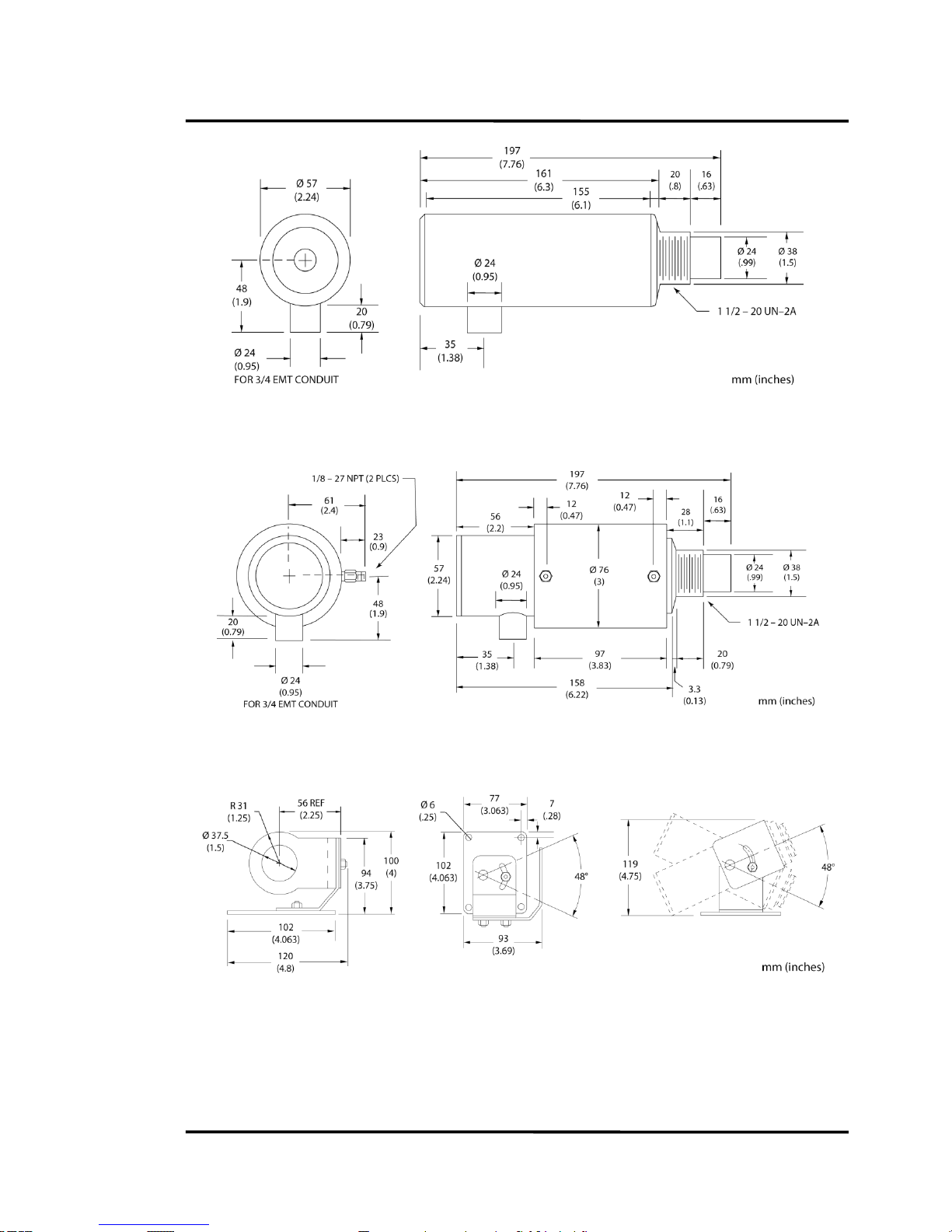
3.4 Dimensions
The following illustrations show dimensions of a standard sensor, see Figure 5, a sensor with the
air/water-cooled housing option, see Figure 6, and the adjustable bracket.
Dimensions are listed for your installation convenience.
Sensor
Trigger
GND
Page 15
Technical Data
Marathon MR Rev. E2 04/2011 15
Figure 5: Dimensions of Sensing Head
Figure 6: Sensing Head with Air/Water-Cooled Housing Option
Figure 7: Adjustable Bracket
Page 16
Technical Data
16 Rev. E2 04/2011 Marathon MR
3.5 Optical Specifications
Optical Resolution D:S (assumes 95% energy at the focus point)
MR1SA 44:1
MR1SB 82:1
MR1SC 130:1
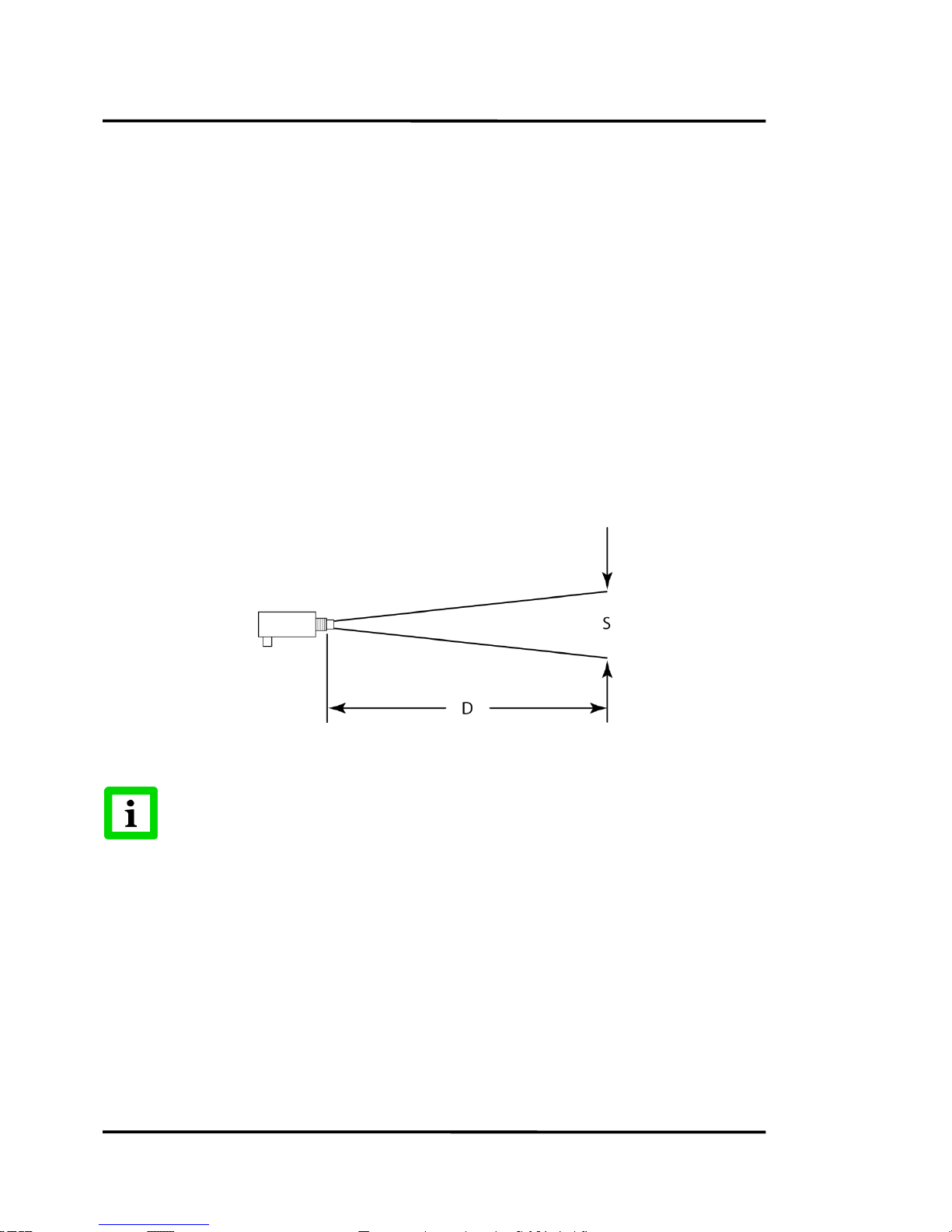
Because the sensor has variable focus, through-the-lens sighting, and parallax-free optics, it can be
mounted almost anywhere. SF (Standard Focus) models can be focused from 600 mm (24 in) to
infinity, and CF (Close Focus) models can be focused from 300 mm (12 in) to 600 mm (24 in). For
1-color temperature measurements make sure the target completely fills the measurement spot. The
spot size for any distance, when the unit is properly focused, can be figured by using the following
formula and Figure 8.
Divide the distance (D, in Figure 8) by your model’s D:S number. For example, if a model C unit (D:S =
130:1) is 2000 millimeters (80 inches) from the target, divide 2000 by 130 (80 by 130), which gives you a
target spot size of 15 mm (0.6 in). A model A unit (D:S = 44:1) at 2000 mm (80 in) would measure a
target spot of 45 mm (1.8 in). Divide 2000 by 44 (80 by 44).
Figure 8: Spot Size Chart
D:S is a ratio and applies to either metric or non-metric measurements!
D = Distance
S = Spot size
Page 17

Technical Data
Marathon MR Rev. E2 04/2011 17
3.6 Scope of Delivery
The scope of delivery includes the following:
Marathon MR Documentation and Support CD
Adjustable mounting bracket (XXXTXXACAB) with mounting nut
End cap for display
The cable with the terminal block needs to be ordered separately!
Page 18

Environment
18 Rev. E2 04/2011 Marathon MR
4
Sensor location and configuration depends on the application. Before deciding on a location, you need
to be aware of the ambient temperature of the location, the atmospheric quality of the location
(especially for 1-color temperature measurements), and the possible electromagnetic interference in
that location. If you plan to use air purging, you need to have an air connection available. Also, wiring
and conduit runs must be considered, including computer wiring and connections, if used. The
following subsections cover topics to consider before you install the sensor.
4.1 Ambient Temperature
The sensing head is designed to operate in ambient temperatures between 0°C (32°F) and 50°C
(122°F). The internal ambient temperature can vary from 10°C (50°F) to 68°C (154°F). Internal
temperatures outside this range will cause a failsafe error. In ambient conditions above 50°C (122°F),
an optional air/water-cooled housing is available to extend the operating range to 120°C (250°F) with
air cooling, or 175°C (350°F) with water cooling. When using the water cooled housing, it is strongly
recommended to also use the air purge collar to avoid condensation on the lens. In ambient conditions
up to 315°C (600°F), the ThermoJacket accessory should be used.
When using air or water cooling and air purging, make sure air and water supplies are installed
before proceeding with the sensor installation.
Water and air temperatures for cooling should be 15-30°C (60-86°F) for best performance. Chilled
water or air below 10°C (50°F) is not recommended. For air purging or air cooling, clean (filtered) or
“instrument” air is recommended.
4.2 Atmospheric Quality
Smoke, fumes, dust, and other contaminants in the air, as well as a dirty lens are generally not a
problem when using the 2-color mode (as long as the attenuation is equal in both spectral bands).
However, if the lens gets too dirty, it cannot detect enough infrared energy to measure accurately, and
the instrument will indicate a failure. It is good practice to always keep the lens clean. The Air Purge
Collar helps keep contaminants from building up on the lens.
If you use air purging, make sure an air supply with the correct air pressure is installed before
proceeding with the sensor installation.
4.3 Electrical Interference
To minimize electrical or electromagnetic interference or “noise” be aware of the following:
Mount the electronics enclosure as far away as possible from potential sources of electrical
interference such as motorized equipment producing large step load changes.
Use shielded wire for all input and output connections.
Make sure the shield wire from the electronics to terminal block cable is earth grounded.
For additional protection, use conduit for the external connections. Solid conduit is better than
flexible conduit in high noise environments.
Do not run AC power for other equipment in the same conduit.
Page 19

Installation
Marathon MR Rev. E2 04/2011 19
5
5.1 Mechanical Installation
After all preparations are complete, you can install the sensor.
How you anchor the sensor depends on the type of surface and the type of bracket you are using. As
noted before, all sensors, whether standard or with the air/water-cooled housing option, are supplied
with an adjustable bracket and mounting nut. You can also mount the sensor through a hole, on a
bracket of your own design, or on one of the other available mounting accessories, see section
8 Accessories, Seite 39. If you are installing the sensor in a ThermoJacket accessory, you should use the
appropriate mounting device. (Refer to the ThermoJacket manual for further details.) If you do not
have the focusing tool accessory, the sensor must be focused before mounting inside a ThermoJacket
or before attaching an air purge collar.
5.1.1 Distance to Object
The Standard Focus sensor can be focused from 600 mm (24 in) to infinity, and the Close Focus sensor
can be focused from 300 mm (12 in) to 600 mm (24 in), so sensor placement can be varied to suit the
application. The following sections show sensor placement and the various conditions where 2-color
temperature measurements can be taken.
When installing the sensor, check for any high-intensity discharge lamps or heaters that
may be in the field of view (either background or reflected on a shiny target)! Reflected
heat sources can cause a sensor to give erroneous readings.
5.1.2 Sensor Placement (1-Color Mode)
Sensor placement for one-color temperature measurements is more critical than two-color
measurements. The sensor must have a clear view of the target. There can be no obstructions on the
lens, window, or in the atmosphere. The distance from the target can be anywhere beyond the
minimum requirements, as long as the target completely fills the field of view. The following figure
illustrates proper placement when using the one-color mode.
Figure 9: Proper Sensor Placement in 1-Color Mode
Target greater than spot size
Target equal to spot size
Target smaller than spot size
best
good
incorrect
Page 20

Installation
20 Rev. E2 04/2011 Marathon MR
5.1.3 Sensor Placement (2-Color Mode)
The following figure shows head placement under various conditions where two-color temperature
measurements can be taken. Note, however, that if the sensor signal is reduced more than 95%
(including emissivity and obscuration of the target), the sensor accuracy also degrades.
Figure 10: Sensor Placement in 2-Color Mode
Emitted
energy
Emitted
energy
Sighting hole smaller than the
sensor’s field of view
Emitted
energy
Target smaller than field of view
and/or moves or vibrates in and
out of field of view (e.g. wire)
Emitted
energy
Smoke, steam, dust,
gas in atmosphere
Dirty lens or dirty sighting window
Page 21

Installation
Marathon MR Rev. E2 04/2011 21
5.1.4 Viewing Angles
The sensor can be placed at any angle from the target up to 30° for one-color mode, or 45° for twocolor mode.
Figure 11: Acceptable Sensor Viewing Angles
Minimum Distance
SF: 600 mm (24 in)
CF: 300 mm (12 in)
Best
90° to target
Acceptable
Viewing Angles
Bad
1-Color Mode: greater than 30° to target
2-Color Mode: greater than 45° to target
Good
1-Color Mode: 30° to target
2-Color Mode: 45° to target
Page 22

Installation
22 Rev. E2 04/2011 Marathon MR
5.1.5 Aiming and Focusing
Once you have the sensor in place, you need to aim and focus it on the target. To aim and focus the
sensor, complete the following:
1. Loosen the nuts or bolts of the mounting base. (This can be either a factory-supplied accessory
or customer-supplied base.)
2. Look through the eyepiece and position the sensor so the target is centered as much as possible
in the middle of the reticle, see Figure 12. (Note that the target appears upside down.)
3. Turn the lens holder clockwise or counter-clockwise until the target is in focus. You can tell the
lens is focused correctly by moving your eye from side to side while looking through the
eyepiece. The target should not move with respect to the reticle. If it does, keep adjusting the
focus until no apparent motion is observed.
4. Check once more to make sure the target is still centered, and secure the mounting base.
Focusing is complete.
Figure 12: Sensor Eyepiece and Reticle
Target
Sighting Scope
Reticle
Area to measure
(inside recticle)
Page 23

Installation
Marathon MR Rev. E2 04/2011 23
5.2 Electrical Installation
5.2.1 DIN Connector Wiring
If you need to wire a new DIN connector or rewire the supplied connector, refer to the following
illustration and table for the wiring layout.
Figure 13: DIN Connector Pin Layout (Pin Side)
Pin
Color
Description
A
Black*
Rx A B White*
Rx B C Grey*
Tx B D Purple*
Tx A E White/Drain
Shield
F
Yellow
Trigger
G
Orange
Relay COM
H
Blue
Relay NO/NC
J
Green
+ mA Out
K
Brown
– mA Out
L
Black
Power Ground
M
Red
+ 24 VDC
Note: Twisted Pairs
– Black & White
– Grey & Purple
Figure 14: DIN Connector Wiring
5.2.2 Cables and Terminal Block
Sensor cables can be ordered in several lengths. They come with a 12-pin DIN plug on one end and
bare wires on the other. An external terminal block is included with each sensor cable and is labeled as
shown in Figure 15.
E F G
B A K
D
M
C
L
H
J
Page 24

Installation
24 Rev. E2 04/2011 Marathon MR
Figure 15: Terminal Block
To connect the bare wires to the terminal block, attach the sensor cable wires to the color coded side of
the terminal block. Match the wire’s colors to the appropriately labeled terminals. If necessary, use
Figure 15 as a guide. The connections on the opposite side of the terminal are discussed in the
following subsections. If you cut the cable to shorten it, notice that both sets of twisted-pair wires
have drain wires inside their insulation. These drain wires (and the white wire that is not part of
the twisted pair) must be connected to the terminal labeled CLEAR. (Only necessary if you cut the
cable.)
Incorrect wiring can damage the sensor and void the warranty. Before applying power,
make sure all connections are correct and secure.
The terminal block is susceptible to electrostatic discharge. You should mount it in a
protective case.
Power supply
RS485 Transmit
RS485 Receive
MilliAmp output
Relay outputs
Neutral ground
twisted-pair cables (do not confuse with single black and single white cables)
Page 25

Installation
Marathon MR Rev. E2 04/2011 25
When using conduit for the cable, and when it has a compression fitting installed on
the conduit connection, the sensor head is rated NEMA-4 (IEC 529, IP65).
The sensor cable may be shortened but not lengthened without the appropriate
terminal block accessory. Longer cables are available from the factory. Limit power
cables to 60 m (200 ft) or less. RS485 cables can be extended up to 1200 m (4000 ft).
Avoid installing the sensor cable in noisy electrical environments such as around
electrical motors, switch gear, or induction heaters.
5.2.3 Power Supply
Connections from a 24 VDC (500 mA or higher) power supply attach to the appropriate terminals on
the electronic enclosure’s terminal strip.
Isolated power is required, and this is provided by the appropriate manufacturer
supplied power supply accessory. Beware of use of other power supplies which may
not provide the necessary isolation and could cause instrument malfunction or damage!
Page 26

Installation
26 Rev. E2 04/2011 Marathon MR
5.2.4 PC Connection via USB/RS485 Converter
To connect to a computer’s USB port, you need one of the USB/RS485 Converter accessories (similar to
the following figure) and the proper USB cable.
The distance between the sensor and a computer can be up to 1200 m (4000 ft.) via RS485 interface.
This allows ample distance from the harsh environment where the sensing system is mounted to a
control room or pulpit where the computer is located. The USB/RS485 converter is self-powering via
the USB connection.
Figure 16: USB/RS485 Converter (XXXUSB485)
Figure 17: Wiring the Sensor’s RS485 Interface (left)
with USB/RS485 Converter (right)
Sensor
Converter
Page 27

Installation
Marathon MR Rev. E2 04/2011 27
5.2.5 PC Connection via RS232/485 Converter
To connect to a computer’s RS232 port, you need one of the Interface Converter accessories (see table
below) and the proper RS232 cable. If your computer has an RS485 interface card, you can connect the
sensor directly to its port (using the proper connector) with wiring from the electronic enclosure’s
terminal block.
Do not use other commercially available converters, they do not have the necessary
features!
Order number
Model
XXX485CVT
25 pin to terminal strip interface converter, recommended for direct
wiring between a serial interface and the terminal block
XXX485CVT1
XXX485CVT with 110 VAC power adapter
XXX485CVT2
XXX485CVT with 230 VAC power adapter
XXX485CV
25 pin to 25 pin interface converter
XXX485CV1
XXX485CV with 110 VAC power adapter
XXX485CV2
XXX485CV with 230 VAC power adapter
Table 2: Available RS232/485 Interface Converters
Connect the interface converter to an available COM port on your computer, either directly or with an
appropriate serial cable (available from computer supply stores). If your computer has a 9-pin serial
connector, use the supplied 25-pin to 9-pin cable between the interface converter or cable and the
computer.
Figure 18: RS232/485 Interface Converter, with pins (left, XXX485CV…)
or terminal (right, XXX485CVT…)
The RS485 output is as follows:
Baud rate: 300, 1200, 2400, 9600, 19200, 38400 (default)
Data format: 8 bit, no parity, 1 stop bit
4-wire, full duplex, point-to-point
not
used
RS232 25-pin female connector
RS232 25-pin female connector
RS485 25-pin male connector
RS485 Connector (screw terminals)
Optional power connector
9 VDC as alternative to
24 VDC power supplement
Optional power connector
9 VDC as alternative to
24 VDC power supplement
From electronics housing ...
Page 28

Installation
28 Rev. E2 04/2011 Marathon MR
Adjustable baud rate only available through 2-way RS485.
To set up your computer to initialize the sensors, complete the following steps:
1. Remove power from the MR sensor!
2. Install all electronics wiring!
3. Plug the RS232/485 interface converter into your computer’s serial port, or attach it to a serial
cable connected to the computer! Use 9 pin to 25 pin converter if necessary!
4. If the 9 VDC power supply is used, apply power to the RS232/485 converter!
5. Apply power to the MR sensor!
6. Turn on your computer!
You need to make sure another serial device (e.g. an internal modem) is not using the
identical COM-port at the same time!
Always make all electrical connections before applying power to the MR sensor! Do not
change RS485 or power connections on the RS232/485 converter while the MR sensor has
power applied, as this may cause damage to the Interface converter!
In 4-wire communication the data can be transferred in both directions, from sensor to PC and reverse.
4-wire communication should be preferred compared to 2-wire communication (for 2-wire
communication see appendix 11.4 2-Wire Communication, Seite 57).
For an installation of two or more sensors in a network, each sensor cable is wired to its own terminal
block. The RS485 terminal lines on each terminal block are wired in parallel.
Figure 19: 4-Wire Multidrop Wiring in a Network
RS232/485
Interface Converter
XXX485CVT2
Terminal Block
from Sensor
from additional terminal block
of another sensor
9 VDC power ... or 24 VDC power supply
Page 29

Installation
Marathon MR Rev. E2 04/2011 29
5.2.6 Addressing
If you are installing two or more sensors in a multi-drop configuration, please be aware of the
following:
Each sensor must have a unique address greater zero.
Each sensor must be set to the same baud rate.
The addressing of a sensor can be done by means of the Multidrop Software (Menu <Sensor Setup>)
that came with your sensor. An alternative would be to use the specific interface commands of the
sensor in conjunction with a standard terminal program (e.g. Windows HyperTerminal), see section
9.5 Command List, page 47.
To set up your computer to initialize the sensors, complete the following stepps:
Attach each sensor individually in 4-wire mode to the computer.
Start the DataTemp Multidrop software.
In the DataTemp MultiDrop Startup Wizard, select the correct COM port and ASCII protocol,
then <Scan All Baud Rates> for a <Single Sensor>. DataTemp MultiDrop should find the single
MR unit connected to the computer serial port.
Once DataTemp Multidrop is running, go to the <Setup> menu and select <Sensor Setup>.
In the <Sensor Setup> menu select the <Advanced Setup> tab. This tab contains the
Communications Interface menu. The Interface Menu allows you to set the <Polling Address>,
<Baud Rate> and <RS485 Mode>. Each unit needs a unique address, but the same <Baud Rate>
and <RS485 Mode> settings.
Once all the units are addressed, wire up the units in the either the 2-wire or 4-wire multidrop
manner, keeping all TxA's, TxB's, RxA's and RxB's to be common.
Now you can run DataTemp Multidrop Software and by selecting the baud rate that you set,
the program will quickly identify all of the units attached on the network and you're up and
running.
Page 30

Operation
30 Rev. E2 04/2011 Marathon MR
6
Once you have your sensor(s) positioned and connected properly, the system is ready for continuous
operation. Operation is accomplished either through the back panel or through controlling software.
A setup and configuration program is supplied with your sensor. You can also create custom
programs using the communications protocols listed in Section 9 Programming Guide on page 44.
6.1 Control Panel
The sensor is equipped with a control panel, which has setting/controlling buttons and an LED
display. The panel is used primarily for setting up the instrument and is covered over during normal
use.
The control panel is protected by the supplied end cap. The sighting hole in the end cap is threaded to
accept the polarizing filter accessory (used for sighting/focusing on very bright targets). An end cap
with a larger window, which allows all control panel LED’s to be visible, is available as an option.
(You cannot use the polarizing filter with this option.)
You can configure sensor settings with the control panel or with a computer. The panel is used
primarily for setting up the instrument. The buttons and LED’s are defined in the following sections.
Allow the electronics to warm up for 15 minutes before making control panel
adjustments!
Figure 20: Control Panel
The sensor has a remote locking feature that keeps the unit from being accidentally changed from the
control panel (locked by default in multidrop mode). This lockout mode denies access to all the
switches on the control panel. It is available through the RS485 connection and can be unlocked only
by a command from the remote computer.
On the sensor’s back panel is a switch that is labeled “S” and “A.” Make sure the switch is always in
the “A” position, the “S” position is for servicing only.
Mode Selection
Switches between 1C and 2C
Display
Temperature Unit Indicator: °C or °F
E-Slope/Emissivity
Peak Hold
Averaging
Sighting scope
Raises selected function value
Lowers selected function value
Page 31

Operation
Marathon MR Rev. E2 04/2011 31
6.2 Operation Modes
When you first turn the unit on, the display shows the current temperature. Pushing the mode selector
button will change the figures on the display to the current setting for each particular mode. Figure 21
illustrates the sequence of operation for the mode selector button when in current temperature mode.
Figure 21: Mode Selector Button Sequence
6.2.1 Temperature Display
The temperature display can be set for either °C or °F by pressing the C/F selector button ( – up
arrow), which also doubles as the Increase Value button for the other modes. The Decrease Value
(– down arrow) button is inactive in this mode. A lit LED shows you whether the measured
temperature is in °C or °F. Note that this setting influences the RS485 output for both target and
internal temperatures.
6.2.2 Emissivity (1-Color)
You can set the unit up for either 1-color or 2-color measurements. The 1C/2C selector button on the
control panel switches between the two functions. One of the red LEDs, labeled 1C and 2C, will show
what function is active.
The emissivity is a calculated ratio of infrared energy emitted by an object to the energy emitted by a
blackbody at the same temperature (a perfect radiator has an emissivity of 1.00). The emissivity is
preset at 1.00. For information on determining an unknown emissivity, and for sample emissivities,
refer to section 11.1 Determination of Emissivity and 11.2 Typical Emissivity Values, p. 54f.
To change the unit’s emissivity setting, complete the following:
1. Make sure the 1C LED is lit.
2. Press the Mode button until the Є LED is lit. The current emissivity value shows on the
display.
3. Press the or button to change the value.
4. Press the Mode button several times until the C or F LED is lit. The displayed temperature
will now be based on the new emissivity value.
Display/Change emissivity (1-color mode)
default: 1.00
Display/Change slope (2-color mode)
default: 1.000
Display current temperature
Switches between °C and °F
Raises and lowers emissivity
or slope
Display/Change peak hold setting
default = 0 sec / off
Raises and lowers
peak hold timing
Display/Change averaging setting
default = 0 sec / off
Raises and lowers
averaging time
Page 32

Operation
32 Rev. E2 04/2011 Marathon MR
6.2.3 Slope (2-Color)
The slope is the quotient of the emissivities based on the narrow and the wide spectral range (first and
second wavelength). The slope is preset at the factory at 1.000.
The slope is the deciding parameter for measurements in 2-color mode! The emissivity
affects only measurements in 1-color mode.
For information on determining an unknown slope, and for sample slopes, refer to section 11.3 Typical
Slopes, p. 56.
To change the unit’s slope setting, complete the following:
1. Make sure the 2C LED is lit.
2. Press the Mode button until the Є LED is lit. The current slope value shows on the display.
3. Press the or button to change the value.
4. Press the Mode button several times until the C or F LED is lit. The displayed temperature
will now be based on the new slope value.
6.2.4 2C/1C Switch
To switch between 2-color and 1-color temperature measurement push the 2C/1C selector button. A lit
LED indicates the active measurement method. Switching affects the LED display and analog out but
not the RS485 out.
6.2.4.1 Peak Hold (PKH)
With Peak Hold, the respective last peak value is held for the duration of Hold Time.
To set and activate Peak Hold, do the following:
1. Press the Mode button until the PKH LED is lit.
2. Press the button to both set and activate. The display reads in 0.1 seconds. Set Peak Hold
from 0.1 to 299.9 seconds. If Peak Hold is set to 300.0 seconds, a hardware reset is needed to
trigger another reading. If Peak Hold is set to 0.0 seconds, the function is deactivated.
3. Press the Mode button until the C or F LED is lit. If Peak Hold has been activated, the Peak
LED will stay lit.
Once Peak Hold is set above 0, it automatically activates. The output signal remains the same until one
of two things happens:
The peak hold time runs out. In this case, the signal reverts to actual temperature.
The actual temperature goes above the hold temperature. In this case, starts holding new
peak.
Note that other hold functions (like Averaging) cannot be used concurrently. By means of the
software other hold functions are adjustable (e.g. Advanced Peak Hold).
6.2.4.2 Averaging (AVG)
Averaging can be useful when an average temperature over a specific duration is desired, or when a
smoothing of fluctuating temperatures is required.
Page 33

Operation
Marathon MR Rev. E2 04/2011 33
The averaging algorithm simulates a first order low pass RC filter whose time constant can be
adjusted to match the user’s averaging needs. The following figure illustrates an averaging output
signal.
Figure 22: Averaging Example
To set and activate Averaging, do the following:
1. Press the Mode button until the AVG LED is lit.
2. Press the button to both set and activate. The display reads in 0.1 seconds. Set Average
anywhere from 0.1 to 300.0 seconds. If Average is set to 0.0 seconds, the function is
deactivated.
3. Press the Mode button until the C or F LED is lit. If Average has been activated, the AVG LED
will stay lit.
Once Averaging is set above 0, it automatically activates. Note that other hold functions (like Peak
Hold) cannot be used concurrently.
Hot objects moving on a production line
Standard output signal
Average output signal
Page 34

Operation
34 Rev. E2 04/2011 Marathon MR
6.2.5 Overview to Hold Functions
The following table lists the various Hold functions along with their resets and timing values. Use this
table as a guide for programming your sensor and adjusting the Hold times.
Please note, the setting of some commands is not possible by using of the control panel, these
commands are only available by means of the software.
Hold Function
RESET by
Peak Time
Valley Time
Threshold
Hysteresis
Decay Rate
Protocol code
P F C
XY
XE
none
none
000.0
000.0
-*
-*
-*
Peak Hold
timer
000.1-299.9
000.0
000.0
-*
000.0
Peak Hold
trigger
300.0**
000.0
000.0
-*
000.0
Peak Hold with decay
timer
000.1-299.9
000.0
000.0
-*
0001-9999
Advanced Peak Hold
trigger or
threshold
300.0
000.0
0250-3000
-*
0000
Advanced Peak Hold
timer or
threshold
000.1-299.9
000.0
0250-3000
-*
0000
Advanced Peak Hold with
decay
timer or
threshold
000.1-299.9
000.0
0250-3000
-*
0001-9999
* Value does not affect the function type
** Holds indefinitely or until triggered
Table 3: Hold Functions
Page 35

Operation
Marathon MR Rev. E2 04/2011 35
6.2.6 Setpoints
The two Setpoints are deactivated by default (alarm mode). Activating and adjusting the Setpoints is
accomplished through software. Once one or both Setpoints are activated the relay changes state as
the current temperature passes the setpoint temperature.
6.2.7 Deadband
Deadband is a zone of flexibility around the Setpoint. The alarm does not go abnormal until the
temperature exceeds the Setpoint value by the number of set deadband degrees. Thereafter, it does not
go normal until the temperature is below the Setpoint by the number of set deadband degrees. The
Deadband is factory preset to ± 2° C or F of Setpoint value. Adjusting to other values is accomplished
through software. For information on the sensor’s communication protocols, see Section
9 Programming Guide Seite 44. The following figure is an example of the Deadband around a Setpoint
temperature of 960°C (1760°F).
Figure 23: Deadband Example
962°C
958°C
Setpoint: 960°C
Relay Changes State
Time
Normal State
Alarm
Alarm
Normal State
Deadband
Object Temperature
Page 36

Operation
36 Rev. E2 04/2011 Marathon MR
6.3 Inputs and Outputs
6.3.1 Milliamp Output
The milliamp output is an analog output you can connect directly to a recording device (e.g., chart
recorder), PLC, or controller. The analog output resolution for all models is 0.5°C or 1°F. The mA
output can be forced to a specific value, underrange, or overrange with a RS485 command. This
feature is useful for testing or calibrating connected equipment.
6.3.2 Relay Outputs
The relay output is used as an alarm for failsafe conditions or as a setpoint relay, refer to Section
10.2 Fail-Safe Operation, on page. 50. Relay outputs relate to the currently displayed temperature on
the LED display. The relay output can be used to indicate an alarm state or to control external actions.
The relay can be set to either NO (Normally Open) or NC (Normally Closed) with a 2- way RS485
command (depending on the compatibility requirements of connected equipment). The relay can be
forced on or off via the 2-way for testing connected equipment.
6.3.3 Trigger
Peak Hold can be Reset by shorting the Trigger input (labeled TRIG) to Ground (labeled GND) for a
minimum of 10 msec. This can be done either with a momentary switch or a relay. Peak Hold has to be
set to 300.0 seconds to recognize this Reset. The Reset signal will cause the peak reading that the
sensor is holding to change immediately to the current target temperature.
Page 37

Operation
Marathon MR Rev. E2 04/2011 37
6.4 Factory Defaults
To globally reset the unit to its factory default settings, press the and buttons at the same time for
approximately 2 seconds. The baud rate will not change from the last value when this is done.
Parameter
As shipped from Factory (Defaults)
Display mode
2-color mode, degrees C, TEMP display
Emissivity
1.00
PKH
0.0
AVG
0.0
Baud rate
38400 baud *
Temperature Setting for 4 mA
Low end of sensor temperature range **
Temperature Setting for 20 mA
High end of sensor temperature range **
Serial Output Transmission Mode
Burst mode, Default string = UTSI
Relay Output Control
Controlled by unit, NO function (indicates failsafe alarms)
Set Output Current
Controlled by unit, 4-20 mA
Lockout Switch Panel Access
Unlocked
Communications Mode
Standalone ***
RS485 Mode
4-wire ***
* Note that the default values can be loaded into the sensor by pressing the (up) and (down) buttons
together for about 2 seconds or by 2-way instructions. The baud rate will not change from the last value when
this is done. Factory defaults can be installed with a RS485 command (#XF).
** These parameters can be adjusted both by a RS485 command, which allows you to scale the high and low
temperature points to suit your application.
*** Communications Mode and RS485 Mode, like Baud Rate, are unchanged when the factory defaults are restored
Table 4: Factory Defaults
Page 38

Options
38 Rev. E2 04/2011 Marathon MR
7
Options are items that are factory installed and must be specified at time of order. The following are
available:
ISO Calibration Certificate, based on NIST/DKD certified probes (XXXMRCERT)
Water-Cooled Housing, incl. Air Purge Collar (…W)
7.1 Water Cooled Housing including Air Purge Collar
Figure 24: Sensing Head with Air/Water-Cooled Housing Option
Page 39

Accessories
Marathon MR Rev. E2 04/2011 39
8
8.1 Overview
A full range of accessories for various applications and industrial environments are available.
Accessories include items that may be ordered at any time and added on-site. These include the
following:
Fixed Mounting Bracket (XXXTXXACFB)
Air Purge Collar (XXXTXXACAP)
Polarizing Filter End Cup (XXXTPFEC)
Industrial Power Supply (XXXSYSPS)
USB/RS485 Converter (XXXUSB485), see section 5.2.4, page 26
RS232/485 Interface Converter (XXX485CV…), see section 5.2.5, page 27
Cables in the following lengths: 4, 8, 15, 30, or 60 m (13, 26, 50, 100, or 200 ft.) (XXX2CCB…)
Replacement Window (XXX2CPW)
ThermoJacket enclosure for ambient temperatures to 315°C (599°F) (RAYTXXTJ1M), see also
ThermoJacket documentation
Figure 25: Sensing Head with Air/Water-Cooled Housing Option
8.2 Fixed Mounting Bracket
The Fixed Mounting Bracket accessory can be used if the sensor will always remain in a fixed location.
Adjustable Mounting Bracket
Mounting Nut
Air Purge Collar
Fixed Mounting Bracket
Sensing Head
Sensing Head with Water Cooled
Housing Option
Polarizing Filter
End Cup
Page 40

Accessories
40 Rev. E2 04/2011 Marathon MR
Figure 26: Fixed Mounting Bracket
8.3 Air Purge Collar
The Air Purge Collar accessory is used to keep dust, moisture, airborne particles, and vapors away
from the lens. It can be installed before or after the bracket. It must be screwed in fully. Air flows into
the 1/8” NPT fitting and out the front aperture. Air flow should be a maximum of (0.5 to 1.5 liters/sec
or 0.13 to 0.4 gallon/sec). Clean (filtered) or “instrument” air is recommended to avoid contaminants
from settling on the lens. Do not use chilled air below 10°C (50°F).
Focus the instrument before attaching the air purge collar.
Figure 27:Air Purge Collar
8.4 Polarizing Filter End Cup
The Polarizing Filter can be screwed into the viewing port to provide eye protection when sighting on
bright, high temperature targets. The filter does not affect measured energy. It is solely for viewing
comfort. Rotate the outer portion of the filter until you achieve the desired visual attenuation.
Page 41

Accessories
Marathon MR Rev. E2 04/2011 41
Figure 28 Polarizing Filter
8.5 Cables
The cable comes with terminal block. The cable is 2 twisted pairs and 8 separate wires. The overall
shield is aluminized mylar and 85% braided tinned copper. The following are descriptions of the 12
wires:
Power—2 wires (Black/Red)
Conductor: AWG 22/7x30 tinned copper
Insulation: FEP .006” wall
Shield: None
RS485—2 twisted pairs (Black/White and Purple/Gray)
Conductor: AWG 24/7x32 tinned copper
Insulation: FEP .006” wall
Shield: Aluminized mylar with drain wire
Outputs and Ground—6 wires (Green/Brown/Blue/Orange/Yellow/Clear)
Conductor: AWG 24/7x32 tinned copper
Insulation: FEP .006” wall
Shield: None
Cable Diameter: 7 mm (0.256 in) nominal
Temperature: UL rated at –80°C to 200°C (-112°F to 390°F)
High temperature cables have good to excellent resistance to oxidation, heat, weather, sun, ozone,
flame, water, acid, alkalis, and alcohol, but poor resistance to gasoline, kerosene, and degreaser
solvents.
If you purchase your own RS485 cable, use wire with the same specifications as those
listed above. Maximum RS485 cable length is 1200 meters (4000 feet).
Polarizing filter will not fit in glass window end cap. Do not look through the lens at
extremely bright objects with your eyes unprotected. Eye damage could occur.
Page 42

Accessories
42 Rev. E2 04/2011 Marathon MR
If you cut the cable to shorten it, notice that both sets of twisted-pair wires have drain
wires inside their insulation. These drain wires (and the white wire that is not part of
the twisted pair) must be connected to the terminal labeled CLEAR. (Only necessary if
you cut the cable.) Refer to Section 2.3 for terminal block wiring diagram.
Page 43

Accessories
Marathon MR Rev. E2 04/2011 43
8.6 Industrial Power Supply
The DIN-rail mount industrial power supply delivers isolated dc power and provides short circuit
and overload protection.
To prevent electrical shocks, the power supply must be used in protected environments
(cabinets)!
Technical data:
Protection class class II as per IEC/EN 61140
Environmental protection IP20
Operating temperature range -25°C to 70°C (-13°F to 158°F)
AC Input 100 – 240 VAC 50/60 Hz [L/N]
wire size 0.5 to 2 mm² (AWG 24 to 12)
DC Output 24 VDC / 1.25 A [+/–]
wire size 0.5 to 2 mm² (AWG 24 to 12)
Figure 29: Dimension of Industrial Power Supply
Page 44

Programming Guide
44 Rev. E2 04/2011 Marathon MR
9
This section explains the sensor’s communication protocol. Use them when writing custom programs
for your applications or when communicating with your sensor with a terminal program.
9.1 Remote versus Manual Considerations
Since the sensor includes a local user interface, the possibility exists for a person to make manual
changes to parameter settings. To resolve conflicts between inputs to the sensor, it observes the
following rules:
Command precedence: the most recent parameter change is valid, whether originating from
manual or remote.
If a manual parameter change is made, the sensor will transmit a “notification” string to the
host. (Notification strings are suppressed in multidrop mode.)
A manual lockout command is available in the protocols set so the host can render the user
interface “display only,” if desired.
All parameters set via the 2-way interface are retained in the sensor’s nonvolatile memory.
When a unit is placed in multidrop mode its manual user interface is automatically
locked! It can be unlocked with the command XXXJ=U <CR>, where XXX is the
multidrop address.
9.2 Command Structure
Protocols are the set of commands that define all possible communications with the sensor. The
commands are described in the following sections along with their associated ASCII command
characters and related message format information. Types of commands include the following:
1. A request for the current value of a parameter
2. A change in the setting of a parameter
3. Defining the information contents of a string (either continuously output or periodically
polled at the option of the user)
The sensor will respond to every command with either an “acknowledge” or a “not acknowledge”
string. Acknowledge strings begin with the exclamation mark ! and are either verification of a set
command or a parameter value. If the unit is in multidrop mode the 3-digit address can be sent out
before the exclamation mark.
For a change in the setting of a parameter, the range of possible setting values is defined, and, if the
host inputs a value outside the allowed range, an appropriate “error” response character shall be
transmitted back by the sensor.
All commands must be entered in upper case (capital) letters. Also note that leading
and trailing zeros are necessary!
Page 45

Programming Guide
Marathon MR Rev. E2 04/2011 45
Example: Send E=0.90 instead of E=0.9; send P=001.2 instead of P=1.2
After transmitting one command, the host has to wait for the response from the unit before sending
another. A response from the sensor is guaranteed within 4 seconds in Poll mode and 8 seconds in
Burst mode at 300 baud. The response is faster at higher baud rates.
An asterisk * will be transmitted back to the host in the event of an “illegal” instruction. An illegal
instruction is considered to be one of the following:
Any non-used or non-allowed character (unknown command)
An “out-of-range” parameter value
A value entered in the incorrect format (syntax error)
Lower case character(s) entered (all characters must be upper case)
9.3 Transfer Modes
The protocol allows the use of two different modes: the Poll Mode and the Burst Mode
9.3.1 Poll Mode
The current value of any individual parameter can be requested by the host. The unit responds once
with the value at the selected baud rate. Additionally, the user-defined output string can be polled.
9.3.2 Burst Mode
The unit transmits the user-defined output string (continuously, at the selected baud rate), which may
contain all of the parameters. Parameters may also be polled for while the instrument is in burst mode.
The poll string will be inserted in the burst-mode stream.
The sensor transmits the parameters in a fixed order, regardless of the order in which they are
specified. This order is as follows:
1. Temperature unit
2. Target temperature
3. Power
4. Emissivity
5. Peak hold time
6. Average time
7. Mode (Setup/Fast)
8. Internal temperature
9. Temperature setting for 20 mA
10. Temperature setting for 0 mA / 4 mA
11. Output current (specified values, in mA, or controlled by sensor)
12. Multidrop address
13. Trigger status
14. Multidrop address
15. Initialization flag
The following items cannot be placed in the burst output string:
Poll/Burst Mode
Baud rate
Manual Lockout/Unlock
Sensor Model Type
Sensor Serial Number
Page 46

Programming Guide
46 Rev. E2 04/2011 Marathon MR
Relay Control
Laser status
Setpoints
Deadband
Current Output Mode (0 - 20 mA or 4 - 20 mA)
The following items cannot be polled:
Poll/Burst Mode
Baud rate
Relay control
Set current output
An example string for command $=UTQEGH<CR>
The default string is as follows: C T1250 Q0400.023 E1.00 G005.5 H1400 <CR><LF>
9.4 Response Time in Setup Mode
The analog output response time is not guaranteed while a parameter value is being changed or if
there is a continuous stream of commands from the host.
The digital response time specifies how quickly the unit can report a temperature change via RS485 in
burst mode. (Digital response time is not defined for polled mode.) The digital response time is
defined as the time that elapses between a change in target temperature and the transmission of a
burst string reporting the new temperature. Actual digital response time can vary from one reading to
the next, so the digital response time is defined as the “average digital response time.”
The average digital response time depends on the number of characters requested in the output string
and with the baud rate. It may be computed as the following:
b
nt15000
9.9
where:
t = average response time in ms
n = the number of characters in the string including <CR> and <LF>
b = the baud rate
Example:
With a baud rate of 38400, and an output string containing temperature units, 2-color temperature and
ambient (20 characters), the average digital response time would be the following:
mst 7.17
38400
1500020
9.9
Note that the analog output response time is not affected by baud rate or the number of characters
transmitted in the burst string.
Page 47

Programming Guide
Marathon MR Rev. E2 04/2011 47
9.5 Command List
Table describes the commands available for 2-way communications.
Description
Char Format
(2)
P
(1)
B
(1)
S
(1)
N
(1)
Legal Values
Factory Default
Burst string format
$
(3) √ √
(3)
UTSI
Show list of commands
? √
Measured attenuation
B
nn √ √
00 to 99
Baud rate (5)
D
nnn √
003=300 baud
38400
012=1200 baud
024=2400 baud
096=9600 baud
192=19200 baud
√ 384=38400baud
Emissivity
E
n.nn √ √ √
0.10–1.00
1.00
Average time (4)
G
nnn.n √ √ √ √
000.0–299.9 sec
(300 s = )
000.0
Top of mA range
H
nnnn √ √
√ 0000-9999(°C or °F)
High end of
sensor range
Sensor internal ambient
I
nnn √ √
Switch panel lock
J X √ L=Locked
U=Unlocked
Unlocked
Relay alarm output control
K n √ 0=off
2
1=on
2=Normally Open
√ 3=Normally Closed
Bottom of mA range
L
nnnn √ √ √
0000-9999 (°C or °F)
Low end of
sensor range
Mode–MR series
M n √ √ 1=1- color
2 √ 2=2- color
√
F=Fast mode
Target temp – 1-color narrow
N
nnnn √
Output current
O
nn √ √
00=controlled by unit
00
02=under range
21=over range
00–20=current in mA
Peak hold time (4)
P
nnn.n √ √ v √
000.0–299.9 sec
(300 s = )
0000.0
Wide Power
Q
nnnn.nnn
√ v 0000.000–9999.999
Narrow power
R
nnnn.nnn
√ √ 0000.000–9999.999
Table 5 Command List
Notes:
(1) Commands may appear as Polled for (queried), Burst string item,
Set command, or Notification.
(2) n = number, X = uppercase letter.
(3) see section 9.3.2 Burst Mode, Seite 45
(4) Setting Peak Hold cancels Average, and vice-versa.
(5) The sensor restarts after a baud rate change. (Command is not
allowed in broadcast mode.)
Page 48

Programming Guide
48 Rev. E2 04/2011 Marathon MR
Description
Char
MR
Format
(2) P (1) B (1) S (1) N (1)
Legal Values
Factory Default
Slope S √
n.nnn √ √ √ √
0.850–1.150
1.000
Target Temperature 2-color
T √ nnnn √ √
(4)
Temperature units (scale)
U √ X √ √ √ √
C or F
non-US: C US: F
Poll/burst mode
V √ X √
P=Polled B=Burst
Burst
Target temp: 1-color wide
W √ nnnn √ √
(4)
Burst string contents (5)
X$ √ √
Multidrop address
XA √ nnn √ √ √
000 to 032
000
Low temperature limit
XB √ nnnn √
0000–9999 (4)
Set at factory calibration
Deadband (6)
XD √ nn √ √
01–55 in °C
02
01–99 in °F
Restore factory defaults
XF √ √ √
High temperature limit
XH √ nnnn √
0000–9999 (4)
Set at factory calibration
Sensor initialization
XI √ n √ √ √ √
0=flag reset
1
1=flag set
or nothing
Sensor model type
XM X
A, B, C
Set at factory calibration
0-20 mA or 4-20 mA
analog output
XO √ n √ √
0=0-20 mA
4=4-20 mA
4
Sensor revision
XR √ Xn √ Set a factory calibration
Setpoint/Relay function
XS √ nnnn √ √
0000 to 5432 (8)
0000
Trigger
XT √ N √ √ √
XT0=inactive
XT1=active
Identify unit
XU √ Varies √ !XUMR1S
Sensor serial number
XV √ Xnnnnnn
V
Set a factory calibration
Attenuation to activate relay (8)
Y √ nn √ √ √
0 to 95% energy
95%
Attenuation for failsafe
Z √ nn √ √ √
0 to 99% energy reduction
95%
(1) Commands may appear as Polled for (queried), Burst string item, Set command, or Notification.
(2) n = number, X = uppercase letter.
(3) Setting Peak Hold cancels Average, and vice-versa.
(4) In current scale °C or °F
(5) see section 9.3.2 Burst Mode, Seite 45
(6) No effect if relay in alarm mode.
(7) Relay goes to abnormal, display and analog out continue to provide temperature.
(8) 0000 places unit in alarm mode. Non-zero setpoint value puts unit in setpoint mode. Setpoint is in current scale. °C or °F. Must be within unit’s
temperature range.
Table 6: Command List (continued)
Page 49

Programming Guide
Marathon MR Rev. E2 04/2011 49
9.6 Command Examples
HOST
SENSOR
HOST
SENSOR
WHERE USED (1)
Description
Query
Answer
Set
Notification
P B S
N
Burst string format
001?$
001!$UTSI
001$=UTSI
√ √
Show list of commands
001? √ Measured attenuation
001?B
001!B12
√ √ Baud rate
001!D384
001D=384
√
Emissivity
001?E
001!E0.95
001E=0.95
001#E0.95
√ √ √ √ Average time
001?G
001!G001.2
001G=001.2
001#G001.2
√ √ √
√
Top of mA range
001?H
001!H2000
001H=2000
001#H2000
√ √ √ Sensor internal ambient
001?I
001!I028
√ √ Switch panel lock
001?J
001!IJL
001J=L
√ √
Relay alarm output control
001!K0
001K=0
√ √
Bottom of mA range
001?L
001!L1200
001L=1200
√ √ √
Mode – MR series
001?M
001!M1
001M=1
001#M1
√ √ √
√
Target temperature, 1-color narrow
001?N
001!N1158
√ Output current
001!O10
001O=10
√ √ √
Peak hold time
001?P
001!P005.6
001P=005.6
001#P005.6
√ √ √ √ Power
001?Q
001!Q0036.102
√ √ Narrow Power
001?R
001!R0002.890
√ √ Slope
001?S
001!S0.850
001S=0.850
001#S0.850
√ √ √
√
Target temperature,
MR series 2-color
001?T
001!T1225
√ √
Temperature units
001?U
001!UC
001U=C
001#UC
√ √ √ √ Poll/Burst mode
001!VP
001V=P
√
Target temperature, 1-color wide
001?W
001!W1210
√ √ Burst string contents
001?X$
√
Multidrop address
001?XA
001!XA013
001XA=013
√ √ √
Low temperature limit
001?XB
001!XB
√
Deadband
001?XD
001!XD12
001XD=12
√ √
Restore factory defaults
001!XF
XF
001#XF
√ √ High temperature limit
001?XH
001!XH1400
√ Sensor initialization
001?XI
001!XI0
001XI=0
001#XI
√ √ √ √ Laser
001?XL
001!XL1
001XL=1
001#XL1
√ √ √ Sensor model type
001?XM
001!XR
√
0-20 mA or 4 - 20 mA analog output
001?XO
001!XO4
001XO=4
√ √
Sensor revision
001?XR
001!XRF1
√ Setpoint / relay function
001?XS
001!XS1234
001XS=1234
√ √
Trigger
001?XT
001!XT0
001#XT0
√ √ √ Identify unit
001?XU
001!XUMR1
√
Sensor serial number
001?XV
001!XVA099901
√
Attenuation to activate relay
001?Y
001!Y95
001Y=95
√ √ √
Attenuation for failsafe
001?Z
001!Z99
001Z=99
√ √ √
Table 7: Command Examples
(1) P = Poll Mode (Request for a parameters), B = Burst Mode (continuous sending of parameters in the burst string), S = Set
(Command for setting a parameters), N = Notification (Acknowledgment for setting a parameter)
The given examples are related to a unit in a network addressed with address 001. Stand-alone
units are requested without having an address information in the command.
Page 50

Maintenance
50 Rev. E2 04/2011 Marathon MR
10
Our sales representatives and customer service are always at your disposal for questions regarding
application assistance, calibration, repair, and solutions to specific problems. Please contact your local
sales representative if you need assistance. In many cases, problems can be solved over the telephone.
If you need to return equipment for servicing, calibration, or repair, please contact our Service
Department before shipping. Phone numbers are listed at the beginning of this document.
10.1 Troubleshooting Minor Problems
Symptom
Probable Cause
Solution
No output
No power to instrument
Check the power supply
Erroneous temperature
Faulty sensor cable
Verify cable continuity
Erroneous temperature
Field of view obstruction
Remove the obstruction
Erroneous temperature
Window lens
Clean the lens
Erroneous temperature
Wrong slope or emissivity
Correct the setting
Temperature fluctuates
Wrong signal processing
Correct Peak Hold or Average settings
Table 8: Troubleshooting
10.2 Fail-Safe Operation
The Fail-Safe system is designed to alert the operator and provide a safe output in case of any system
failure. Basically, it is designed to shutdown the process in the event of a set-up error, system error, or
a failure in the sensor electronics.
The Fail-Safe circuit should never be relied on exclusively to protect critical heating
processes. Other safety devices should also be used to supplement this function!
When an error or failure does occur, the display indicates the possible failure area, and the output
circuits automatically adjust to their lowest or highest preset level. The following table shows the
values displayed on the LED display and transmitted over the 2-way interface.
Page 51

Maintenance
Marathon MR Rev. E2 04/2011 51
Condition
2-Color
1-Color
(wide band)**
1-Color*
(narrow band)**
Heater control temperature over range
ECHH
ECHH
ECHH
Heater control temperature under range
ECUU
ECUU
ECUU
Internal temperature over range
EIHH
EIHH
EIHH
Internal temperature under range
EIUU
EIUU
EIUU
Wide band detector failure
EHHH
EHHH
<temperature>
Narrow band detector failure
EHHH
<temperature>
EHHH
Energy too low
EUUU
<temperature>
<temperature>
Attenuation too high (>95%)
EAAA
<temperature>
<temperature>
Attenuation too high >95%
("dirty lens", relay will go to “alarm” state)
<temperature>
<temperature>
<temperature>
2-color temperature under range
EUUU
<temperature>
<temperature>
2-color temperature over range
EHHH
<temperature>
<temperature>
Wide band temperature under range
<temperature>
EUUU
<temperature>
Wide band temperature over range
<temperature>
EHHH
<temperature>
Narrow band temperature under range
<temperature>
<temperature>
EUUU
Narrow band temperature over range
<temperature>
<temperature>
EHHH
* only available through RS485
** Wide and narrow band stands for the first and the second wavelength in 2-color mode
*** Note that the activation levels for these conditions may be set to different values. (e.g., "dirty lens" at 95%, EAAA at 98%)
Table 9: Fail-safe Error Codes
The relay is controlled by the temperature selected on the display. If any failsafe code appears on the
display, the relay changes to the “abnormal” state. The exception is the “dirty window” condition.
This causes the relay to change state, leaving a normal numerical temperature output.
Error Code
0 – 20 mA Output
4 – 20 mA Output
no error
according to temperature
according to temperature
ECHH
21 to 24 mA
21 to 24 mA
ECUU
0 mA
2 to 3 mA
EIHH
21 to 24 mA
21 to 24 mA
EIUU
0 mA
2 to 3 mA
EUUU
0 mA
2 to 3 mA
EHHH
21 to 24 mA
21 to 24 mA
EAAA
0 mA
2 to 3 mA
Table 10: Current Output Values in accordance to an Error
If two errors occur simultaneously, the higher priority error is the one that is presented on the LED’s
digital and analog outputs. For example, in 2-color mode, if the internal ambient is too high and the
attenuation is too high, the unit outputs EIHH on the LED’s and digital output and 21 mA on the
analog output. However, since 2-color wide band and narrow band temperatures may all be
presented simultaneously through RS485, their over and under range conditions are independent.
Page 52

Maintenance
52 Rev. E2 04/2011 Marathon MR
Examples of failsafe conditions:
1. One-color temperature is selected for display on the LED’s. Two-color temperature is
transmitted in burst mode. Wide band temperature is under range. Two-color temperature is
999°C.
Outputs:
Display: EUUU
RS485: C T0999
Analog: 2 to 3 mA
Relay: abnormal state
2. Two-color temperature is selected for display on LED’s. All three temperatures are
transmitted in burst mode. Two-color temperature is 1021°C. Wide band temperature is
703°C. Narrow band temperature is 685°C. Attenuation is above 95%, the “dirty window”
threshold.
Outputs:
Display: 1021
RS485: C T1021 W0703 N0685
Analog: scaled to temperature, between 4 and 20 mA
Relay: abnormal state
Page 53

Maintenance
Marathon MR Rev. E2 04/2011 53
10.3 Cleaning the Lens
Keep the lens clean at all times. Any foreign matter on the window will affect 1-color measurement
accuracy and may affect two-color accuracy. However, care should be taken when cleaning the lens.
To clean the window, do the following:
1. Lightly blow off loose particles with “canned” air (used for cleaning computer equipment) or
a small squeeze bellows (used for cleaning camera lenses).
2. Gently brush off any remaining particles with a soft camel hair brush or a soft lens tissue
(available from camera supply stores).
3. Clean remaining “dirt” using a cotton swab or soft lens tissue dampened in distilled water. Do
not scratch the surface.
For finger prints or other grease, use any of the following:
Denatured alcohol
Ethanol
Apply one of the above to the lens. Wipe gently with a soft, clean cloth until you see colors on the
surface, then allow to air dry. Do not wipe the surface dry, this may scratch the surface.
If silicones (used in hand creams) get on the window, gently wipe the surface with Hexane. Allow to
air dry.
10.4 Changing the Window
Sometimes extremely harsh environments can cause damage to the window.
A replacement window (XXX2CPW) is available from the manufacturer.
To replace the sensor’s window, complete the following:
1. With a very small flat-bladed screw driver (e.g., a jeweler’s screwdriver), pry out the
rubberized Buna-N 70 durometer O-ring. The O-ring is set in a groove in front of the window.
2. Turn the sensor face down (window pointing down), and the window should fall out.
3. Turn the sensor face up and insert the new window. (Make sure both sides of the window are
clean.)
4. Replace the O-ring.
Do not use any ammonia or any cleaners containing ammonia to clean the lens. This
may result in permanent damage to the lens’ surface!
If you use a fine-bladed knife to remove the O-ring, be careful not to cut or sever the
ring.
Page 54

Appendix
54 Rev. E2 04/2011 Marathon MR
11
11.1 Determination of Emissivity
Emissivity is a measure of an object’s ability to absorb and emit infrared energy. It can have a value
between 0 and 1.0. For example a mirror has an emissivity of 0.1, while the so-called “Blackbody“
reaches an emissivity value of 1.0. If a higher than actual emissivity value is set, the output will read
low, provided the target temperature is above its ambient temperature. For example, if you have set
0.95 and the actual emissivity is 0.9, the temperature reading will be lower than the true temperature.
An object’s emissivity can be determined by one of the following methods:
1. Determine the actual temperature of the material using an RTD (PT100), a thermocouple, or any
other suitable method. Next, measure the object’s temperature and adjust emissivity setting until
the correct temperature value is reached. This is the correct emissivity for the measured material.
2. If possible, apply flat black paint to a portion of the surface of the object. The emissivity of the
paint must be above 0.98. Next, measure the temperature of the painted area using an emissivity
setting of 0.98. Finally, measure the temperature of an adjacent area on the object and adjust the
emissivity until the same temperature is reached. This is the correct emissivity for the measured
material.
11.2 Typical Emissivity Values
The following table provides a brief reference guide for determining emissivity and can be used when
one of the above methods is not practical. Emissivity values shown in the table are only approximate,
since several parameters may affect the emissivity of a material. These include the following:
1. Temperature
2. Angle of measurement
3. Geometry (plane, concave, convex)
4. Thickness
5. Surface quality (polished, rough, oxidized, sandblasted)
6. Spectral range of measurement
7. Transmissivity (e.g. thin films plastics)
Page 55

Appendix
Marathon MR Rev. E2 04/2011 55
EMISSIVITY AT 1 µM FOR METALS
EMISSIVITY AT 1 µM FOR METALS
Material
Emissivity
Material
Emissivity
Aluminum
Iron, cast
unoxidized
0.1-0.2 oxidized
0.7-0.9
oxidized
0.4 unoxidized
0.35
roughened
0.2-0.8 molten
0.35
polished
0.1-0.2
Magnesium
0.3-0.8
Brass
Molybdenum
polished
0.1-0.3 oxidized
0.5-0.9
Burnished
0.6 unoxidized
0.25-0.35
Chromium
0.4
Monel (Ni-Cu)
0.3
Copper
Nickel polished
0.05 oxidized
0.8-0.9
roughened
0.05-0.2 electrolytic
0.2-0.4
oxidized
0.2-0.8
Silver
0.04
Gold
0.3 Steel Haynes
cold rolled
0.8-0.9
Alloy
0.5-0.9 polished sheet
0.35
Inconel
molten
0.35
oxidized
0.4-0.9 oxidized
0.8-0.9
sandblasted
0.3-0.4 stainless
0.35
electropolished
0.2-0.5
Tin (unoxidized)
0.25
Iron
Titanium oxidized
0.4-0.8 polished
0.5-0.75
unoxidized
0.35 Zinc molten
0.35 oxidized
0.6 polished
0.5
Table 11: Typical Emissivity Values (Metals)
EMISSIVITY AT 1 µM FOR NON-METALS
Material
Emissivity
Asbestos
0.9
Ceramic
0.4
Concrete
0.65
Carbon
unoxidized
0.8-0.95
Graphite
0.8-0.9
Table 12: Typical Emissivity Values (Non-Metals)
Page 56

Appendix
56 Rev. E2 04/2011 Marathon MR
11.3 Typical Slopes
The following slope settings are approximate and will vary depending on the metal alloy and surface
finish, as well as the application. These are supplied here as examples.
Set the slope to approximately 1.000 for measuring the following metals with oxidized surfaces:
• Stainless Steel • Cobalt • Steel
• Iron • Nickel
Set the slope to approximately 1.060 for measuring the following metals with smooth, clean,
unoxidized surfaces:
• Iron • Nickel • Tantalum
• Stainless Steel • Rhodium • Tungsten
• Cobalt • Steel
• Molybdenum • Platinum
Molten iron also has an approximate slope setting of 1.060.
How to determine slope?
The most effective way to determine and adjust the slope is to take the temperature of the material
using a probe sensor such as an RTD, thermocouple, or other suitable method. Once you determine
the actual temperature, adjust the slope setting until the sensor’s temperature reads the same as the
actual temperature reading. This is the correct slope for the measured material.
Page 57

Appendix
Marathon MR Rev. E2 04/2011 57
11.4 2-Wire Communication
Using the 2-wire communication reduces wiring cost in comparison to the 4-wire communications.
2-wire communications is available for network installations, in situations where other sensors are
only able to communicate via 2 wires (e.g. MI sensor). For setting the Interface Converter into the
2-wire communication mode, use the Network Communication Setup Software, found on the software
CD.
Figure 30: 2-Wire Sensor Communication
To Computer
RS232 serial port
RS232/485
Interface Converter
XXX485CVT...
from Sensor
9 VDC power supply or ...
24 VDC power supply
Page 58

Appendix
58 Rev. E2 04/2011 Marathon MR
11.5 Traceability of Instrument Calibration
CU ST OME R INF RAR E D TH ER M O ME TE R S
Computerized cavity
(black body source)
500 to 2727°C
400 to 800°C
Medium Temp Secondary
(Working) Standard
400 to 800°C
Fluke Medium Temp
Primary Standard
760 to 2700°C
High Temp
Primary Standard
760 to 2700°C
High Temp Secondary
(Working) Standard
Working cavaties and plates
(black body sources)
25 to 500°C
-20 to 800°C
Low Temp Secondary
(Working) Standard
-20 to 800°C
Low Temp
Primary Standard
Daily check at 1000,
1700, and 2500°C
Cross check
Annual NIST Calibration
and historical data
results review
Annual NIST Calibration
and historical data
results review
Fluke Calibrated
blackbody cavaties
and plates
Fluke Working
Standards
Fluke Primary
Standards
National Metrology
Institutes
PTB
-50 to 800°C
ITS 90
NIST
800 to 2700°C
ITS 90
Fluke reserves the right to make changes to this traceability and methodes without notice.
Fluke IR Traceability
 Loading...