

Page 1
MX4
TD
Bluetooth
®
HIGH PERFORMANCE
INFRARED THERMOMETER
Rev. H1
01/2005
57701-E1
™
Worldwide Headquarters
Raytek Corporation
1201 Shaffer Road, PO Box 1820
Santa Cruz, CA 95061-1820 USA
Tel: +1 831458 1110
Fax: +1 831425 4561
solutions@raytek.com
www.raytek.com
Raytek China Company
Beijing, China
Tel: +86 10 64 39 22 55
Fax: +86 10 64 37 02 85
info@raytek.com.cn
Raytek Japan, Inc.
Tokyo, Japan
Tel: +81 3 57 33 60 65
Fax: +81 3 57 33 60 99
info@raytekjapan.co.jp
South American Headquaters
Raytek do Brasil
Sorocaba, SP Brasil
Tel: +55 15 32 17 60 46
Fax: +55 15 32 17 56 94
info@raytek.com.br
European Headquarters
Raytek GmbH
Berlin, Germany
Tel: +49 30 4 78 00 80
Fax: +49 30 4 71 02 51
raytek@raytek.de
United Kingdom
Tel: +44 1908 63 08 00
Fax: +44 1908 63 09 00
ukinfo@raytek.com
France
Tel: +33 1 64 53 15 40
Fax: +33 1 64 53 15 44
info@raytek.fr
WARRANTY
Raytek warrants this product to be free from defects in material and
workmanship under normal use and service for a period of one year*
from date of purchase except as hereinafter provided. This warranty
extends only to the original purchaser (a purchase from Raytek or
Raytek’s licensed distributors is an original purchase). This warranty
shall not apply to fuses or batteries. Factory calibration is warranted for
a period of one year. The warranty shall not apply to any product which
has been subject to misuse, neglect, accident, or abnormal conditions of
operation or storage. Should Raytek be unable to repair or replace the
product within a reasonable amount of time, purchaser’s exclusive
remedy shall be a refund of the purchase price upon return of the
product.
In the event of failure of a product covered by this warranty, Raytek will
repair the instrument when it is returned by the purchaser, freight
prepaid, to an authorized Service Facility within the applicable
warranty period, provided Raytek’s examination discloses to its
satisfaction that the product was defective. Raytek may, at its option,
replace the product in lieu of repair. With regard to any covered
product returned within the applicable warranty period, repairs or
replacement will be made without charge and with return freight paid
by Raytek, unless the failure was caused by misuse, neglect, accident,
or abnormal conditions of operation or storage, in which case repairs
will be billed at a reasonable cost. In such a case, an estimate will be
submitted before work is started, if requested.
The foregoing warranty is in lieu of all other warranties, expressed or
implied, including but not limited to any implied warranty of
merchantability, fitness, or adequacy for any particular purpose or use.
Raytek shall not be liable for any special, incidental or consequential
damages, whether in contract, tort, or otherwise.
GARANTIEBEDINGUNGEN
Raytek gewährt für dieses Produkt eine Garantie von einem Jahr*
ab dem Kaufdatum. Der Hersteller garantiert, daß das Produkt im
genannten Zeitraum bei ordnungsgemäßer Anwendung und Wartung
keine Material- und Bearbeitungsfehler aufweist. Ausnahmen sind im
folgenden festgelegt.
Diese Garantie gilt nur für den Ersterwerber (der Erwerb des Produktes
von Raytek oder einem autorisierten Raytek-Händler gilt als
Ersterwerb). Die Garantie erstreckt sich nicht auf Sicherungen oder
Batterien. Für die im Werk vorgenommene Kalibrierung gewährt
Raytek eine Garantiefrist von einem Jahr. Die Garantie schließt keine
Produkte ein, die mißbräuchlich oder fahrlässig verwendet, beschädigt
oder unzulässig betrieben oder gelagert wurden.
Die vorstehenden Garantiebedingungen ersetzen alle anderen eventuell
gemachten ausdrücklichen oder stillschweigenden Zusicherungen.
Raytek übernimmt keine Haftung für einen besonderen, beiläufigen
oder mittelbaren Schaden, gleich ob dieser im Rahmen des Vetrages,
durch eine unerlaubte Handlung oder auf andere Weise entstanden ist.
* European Union (EU): two years/zwei Jahre
* Bluetooth and the Bluetooth logos are trademarks
owned by Bluetooth SIG, Inc., U.S.A. and licensed
to LinTech GmbH, Berlin Germany.
FCC NOTICE
This device complies with Part 15 of the FCC Rules.
Operation issubject to the following two conditions:
(1) this device may not cause harmful interference, and
(2) this device must accept any interference received,
including interference that may cause undesired operation.
NOTE: This equipment has been tested and found to
comply with the limits for a Class A digital device,
pursuant to Part 15 of the FCC Rules. These limits are
designed to provide reasonable protection against
harmful interference when the equipment is operated in
a commercial environment. This equipment generates,
uses, and can radiate radio frequency energy and, if not
installed and used in accordance with the instruction
manual, may cause harmful interference to radio communications. Operation of this equipment in a residential area is likely to cause harmful interference in which
case the user will be required to correct the interference at his own expense.
WARNING: Modifications not expressly approved by
this company could void the user's authority to operate
the equipment.
FCC ID: STG-DFQMX4
Page 2

CONDITIONS DE GARANTIE
Raytek accorde sur ce produit une garantie d’un an* à compter de la
date d’ achat. Le fabricant garantit pendant cette période l’absence de
vice de matériau ou de fabrication, à condition que le produit soit utilisé et entretenu normalement et à l’ exclusion des cas définis
ci-après. La présente garantie ne s’ applique qu’ au premier acheteur
(est considéré comme premier achat l’ acquisition d’un produit vendu
directement par Raytek ou par un distributeur agréé par lui). Les
fusibles et les piles sont exclus de la garantie. Raytek accorde
une garantie d’ un an sur l’ étalonnage effectué en usine.
L‘ utilisation d’ un produit dans un but non conforme à l’ usage
auquel il est destiné, la négligence, l’ utilisation de produits abîmés,
les erreurs d’ utilisation ou de stockage entraînent une exclusion de
garantie.
Dans le cas où Raytek ne serait pas en mesure de réparer ou de
remplacer le produit dans un délai convenable, l’ acheteur pourra
exiger uniquement le remboursement du prix de l’ appareil contre
restitution de ce dernier au vendeur.
Raytek assurera la réparation des appareils tombés en panne pendant
la période de garantie. L’ acheteur expédiera l’ appareil défectueux à
une station technique agréée, à ses frais et pendant le délai de
garantie. Raytek se réserve le droit de procéder à l’ échange de
l’ appareil au lieu de le réparer. La réparation ou le remplacement
seront effectués gratuitement si l’ appareil d éfectueux est retourné
pendant le délai de garantie. Les frais de retour au client seront à la
charge de Raytek. Les frais de réparation seront facturés au client
lorsque la panne sera liée à un défaut de manipulation ou
d‘ utilisation, à de la négligence, à des causes extérieures ou à un
stockage inapproprié. Un devis sera établi avant réparation à la
demande du client.
Les présentes conditions de garantie remplacent toutes les autre
assurances qui auraient pu étre données expressément ou tacitement.
Raytek décline toute respons abilité pour tout dommage particulier,
causé incidemment ou indirectement, que celui-ci soit survenu dans
le cadre du présent contrat ou ait été provoqué par un délit civil ou
par toute autre cause.
* European Union (EU): two years/deux ans
CONDIÇÕES DE GARANTIA
Para o presente produto a Raytek concede uma garantia de um ano*
contados a partir da data de compra. O fabricante garante que
o produto está livre de defeitos de materiais e de fabricação durante o
perídodo mencionado se o produto for devidamente utilizado e
conservado. As exceções são estipuladas a seguir. Esta garantia só
serí1 concedida ao primeiro adquirente (a compra do produto na
Raytek ou num concessioní1rio autorizado da Raytek é considerada
primeira aquisição). A garantia não cobre fusídveis e pilhas. A Raytek
concede uma garantia de um ano para a calibragem feita na fí1brica.
A garantia não inclui produtos utilizados ou danificados indevida
ou negligentemente, produtos usados ou armazenados
inadmissivelmente. Caso a Raytek não esteja em condições de reparar
ou substituir o produto durante um perídodo de tempo apropriado, o
comprador pode solicitar o reembolso do preço contra devolução do
produto como úfanico recurso.
Em caso de um defeito no aparelho durante o perídodo coberto pela
garantia, a Raytek responsabiliza-se pela reparação do mesmo. Cabe
ao comprador enviar o aparelho reclamado por conta própria e durante
o perídodo de garantia para um posto autorizado de assistíancia
técnica. A Raytek reserva-se o direito de substituir o aparelho em vez
de repará-lo. Ao enviar o aparelho defeituoso durante o perídodo de
garantia, a reparação ou a substituição do mesmo são gratuitos. Os
custos da remessa do aparelho ao cliente serão pagos pela Raytek. Se
o defeito resultar de tratamento impróprio, negligíancia, danos
causados por efeitos exteriores, condições inadmissídveis de
utilização ou armazenamento, os custos da reparação serão
correspondentemente faturados. Neste caso é possídvel calcular uma
estimativa dos custos antes da reparação por pedido do clientes
condições de garantia presentes substituem todas as outras garantias
feitas eventualmente explídcita ou implícitamente. A Raytek não se
responsabiliza por danos particulares, acidentais ou diretos, sejam
causados no quadro do presente contrato, em consequíancia de atos
ilídcitos ou de qualquer outra forma.
* European Union (EU): two years/dois anos
CONDICIONES DE GARANTÍA
Raytek concede en relación a este producto una garantía de un año* a
partir de la fecha en que se realice la compra. El fabricante garantiza
que el producto, dentro del espacio de tiempo referido, siempre que se
aplique correctamente y se lleve a cabo el mantenimiento adecuado, no
ha de presentar fallos de material o de fabricación. Más adelante se
mencionará alguna excepción. Esta garantía es válida respecto de la
adquisición primaria (se entiende por adquisición primaria del
producto aquella llevada a cabo directamente de Raytek o bien por
medio de un establecimiento autorizado por Raytek). La garantía no
cubre los fusibles ni las pilas. En relación al calibrado llevado a cabo
en fábrica,
Raytek concede un tiempo de garantía de un año. La garantía no cubre
ningún producto que haya sido usado inadecuada o negligentemente,
se haga hecho funcionar o se haya almacenado estando dañado o de
manera no autorizada.En el caso de que a Raytek no le sea posible
reparar o substituir un producto dentro de un plazo razonable, el
comprador, con carácter de reivindicación jurídica única, puede exigir
la devolución de la suma a la que haya ascendido la compra
devolviendo por su parte el producto en cuestión. En el caso de un
defecto del aparato que tenga lugar durante el tiempo de garantía,
Raytek se hace cargo de la reparación. Para ello, el comprador,
corriendo con los gastos, ha de enviar el aparato que sea objeto de
reclamación a un servicio de reparaciones autorizado dentro del plazo
de validez de la garantía. En caso de que lo considere conveniente,
Raytek se reserva el derecho de substituir el aparato en lugar de
hacerse cargo de la reparación. Si se envía un aparato defectuoso
durante el tiempo en que es válida la garantía, la reparación o bien la
substitución del aparato el cliente una cuenta por los costes
correspondientes a la reparación. En este caso el cliente puede
solicitar un presupuesto para la reparación antes de llevarse ésta a cabo.
Las presentes condiciones de garantía substituyen las demás
eventuales garantías realizadas de modo explícito o implícito. Raytek
no acepta niguna responsabilidad respecto a especiales daños
ocasionales o indirectos, bien hayan acontecido éstos en el marco del
contrato bien se deban a un manejo indebido o a calesquiera otras
causas. defectuoso es gratis. Los costes del envío de vuelta al cliente
corren a cargo de Raytek. En el caso de que el defecto se deba a una
manipulación incorrecta, negligencia, daño causado por agentes
exteriores, almacenamiento o empleo no autorizados, recibirá
* European Union (EU): two years/dos años
Page 3
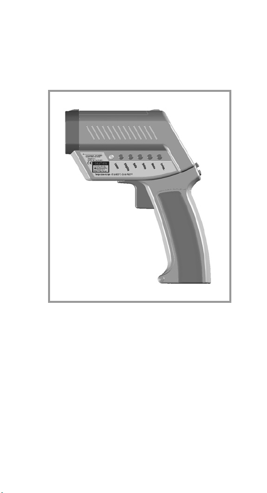
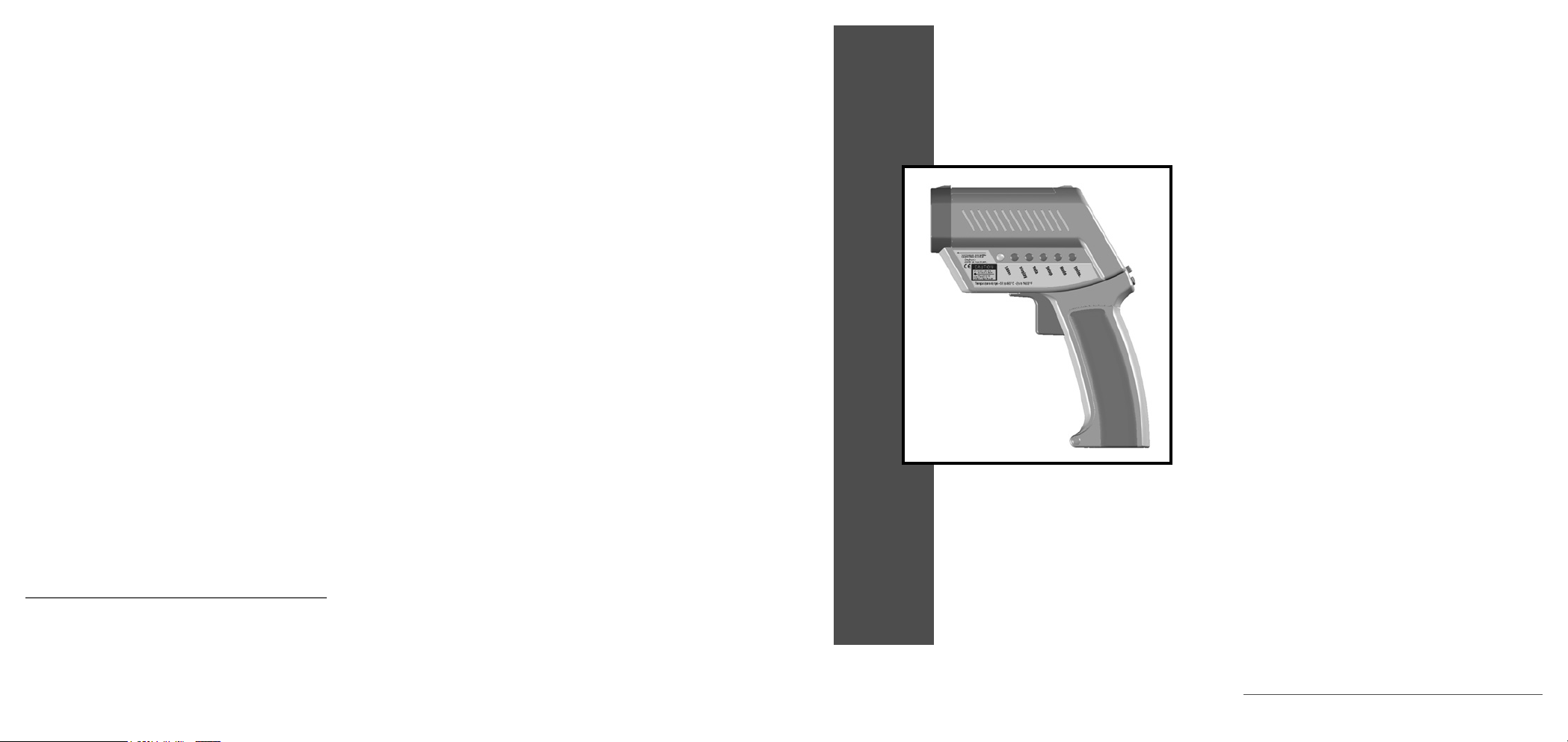
HIGH PERFORMANCE
INFRARED THERMOMETER
Page 4

Page 5

english
Introduction 3
Features/Accessories 3
Functions (User interface) 4
Display 4
Batteries 5
Measurement (Quick Start) 5
Measurement (Continuous) 6
Measurement (Spot size) 6
Selecting a function 7
Laser On/Off 7
Emissivity explained 8
Emissivity adjustment 8
Emissivity Table of Values 9
Emissivity Unknown value 9
Mode Maximum 10
Mode Minimum 10
Mode Difference 11
Mode Average 11
Mode Probe connection 12
Setup High Alarm 13
Setup Low Alarm 13
Setup Time 14
Setup Date 14
Setup Offset 15
Mode Min-Max values 15
Data Logger (How to store data) 16
Data Recall 16
Display (Graphic Display) 17
Display (Auto or Man. range) 17
Display Begin (Man. range) 18
Display End (Man. range) 18
Display Cycle 19
Settings (DIP switch settings) 19
Appendix A: Special order models 23
Appendix B: Troubleshooting 24
Appendix C: Maintenance 25
Appendix D: Laser Warning Label 26
Appendix E: Cautions 27
Appendix F: Emissivities table 29
Specifications 30
Factory Defaults 31
NIST/DKD CE Conformity 32
Table of Contents
Page 6

Page 7
english
We hope you enjoy using
your infrared thermometer!
It measures the amount of
infrared energy emitted by
a target object, and
calculates the temperature
of that object´s surface.
INTRODUCTION
Your thermometer includes:
- Laser sighting
- Adjustable emissivity
- High/Low Alarm
- MAX, MIN, DIF, AVG
- Data Logger (100 points)
- Trigger lock
- Graphic display ... and
more!
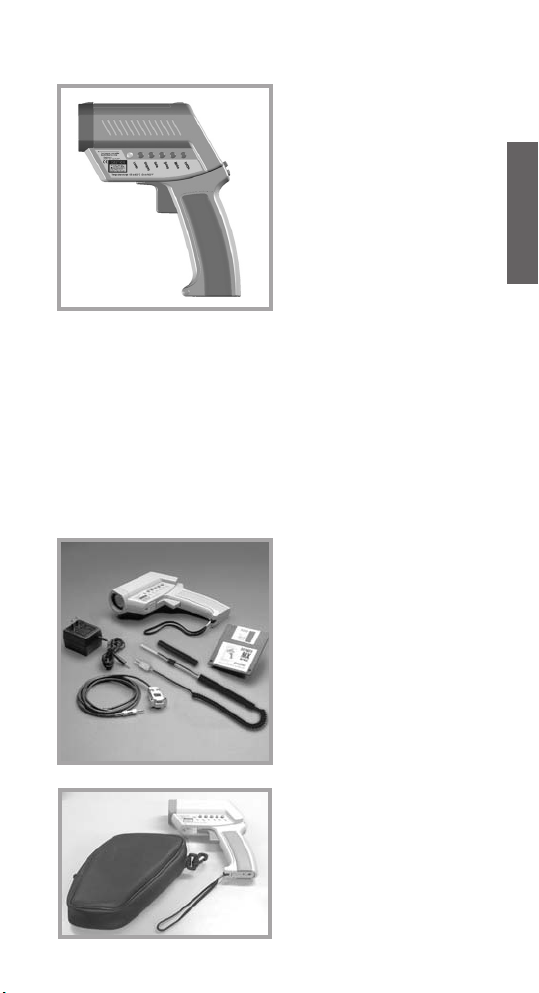
FEATURES
ACCESSORIES
(optional)
The accessories
package for your infrared
thermometer, if ordered,
includes:
- external power supply
- thermocouple type K
- Windows-based software
- RS232 cable
OPTIONAL POUCH
The optional pouch
comes with a belt clip
and helps to protect your
infrared thermometer
when not in use.
3
Page 8
4
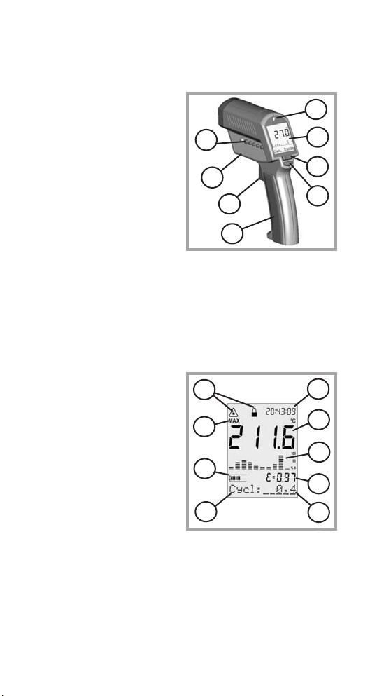
Function keys and display:
(A) Visual and audible
alarm
(B) Display
(C) Up and Down keys
(D) Enter
(E) Handle and battery
compartment
(DIP switches for
adjustments are
inside handle)
(F) Trigger
(G) Tripod mount
(H) 6 main function keys
FUNCTIONS
USER INTERFACE
Displayed functions:
(1) Laser condition /
Lock symbol
(2) Time (or date)
(3) Main temperature
display
(4) Graphic display
(5) Emissivity value
(6) Status bar
(7) Mode indicator
(8) Battery life indicator
(9) MAX, MIN, DIF, AVG
symbols
DISPLAY
A
B
C
D
E
F
G
H
1
2
3
4
5
6
7
8
9
Page 9
english
5
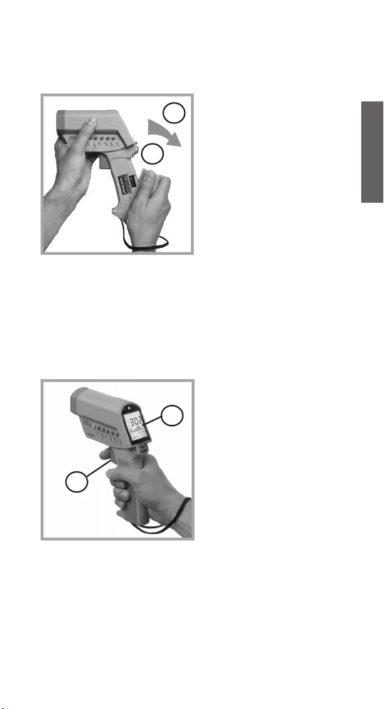
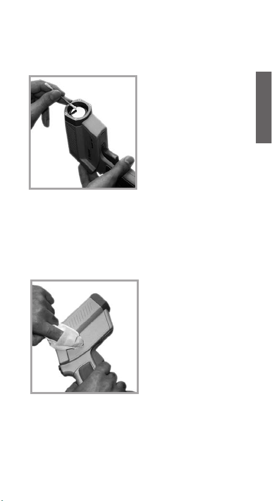
BATTERIES
To open the battery
compartment, press
gently on the top part of
the handle (1) to release
the catch (2) and pivot
the grip as shown in the
figure.
Orient the batteries (two
alkaline R6 (AA, UM3))
as shown on the housing.
MEASUREMENT
QUICK START
To take a temperature
measurement, hold the
unit as shown. Aim at the
target. Pull the trigger (F).
The temperature of the
object being measured is
shown on the display (B).
The temperature will be
displayed for seven
seconds after the trigger
is released.
The unit automatically switches “off” after
7 seconds if a function key is not pressed.
The last settings are stored. The display
returns to the last mode selected.
To recall the last reading, press ENTER
without pulling the trigger.
F
B
2
1
Page 10
6
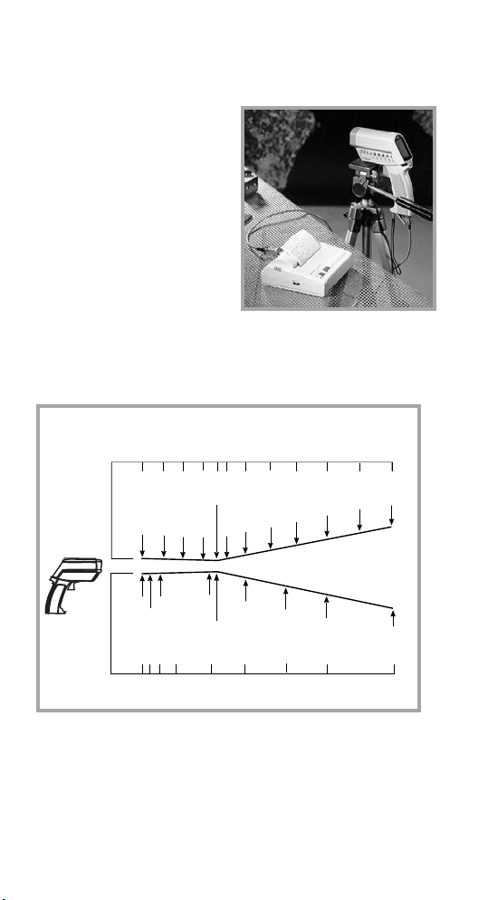
MEASUREMENT
CONTINUOUS
Open the battery compartment and switch LOCK
"on" to lock the unit on.
You may mount the unit on
a tripod, using the tripod
mount. Pull the trigger for
continuous temperature
measurement. (The laser
will not be locked on.)
To unlock, switch LOCK
off.
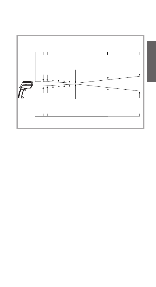
The measured spot size depends on the distance
between the object you are measuring and the infrared
thermometer. The relationship between distance and
spot size is 60:1 at the focus point. The D:S in the far
field (>33ft/10m) is 35:1.
MEASUREMENT
SPOT SIZE
STANDARD MODEL
Optical Chart
DISTANCE: SENSOR TO OBJECT (IN)
0
30
20
36
0.76 IN @ 46 IN
SPOT DIA. (IN)
1.0
0.9
0.81
0.87
84
60
46
48
72
1.51
1.2
0.82
1.85
100
2.3
120
108
2.9
2.5
24
24
0
250
500
100
SPOT DIA. (mm)
DISTANCE: SENSOR TO OBJECT (mm)
FOCUS POINT D:S = 60:1 FAR FIELD D:S = 35:1
29.0
19 mm @ 1150 mm
1000
1500
44.0
2000
58.0
2500
72.0
3000
19.8
23
Page 11
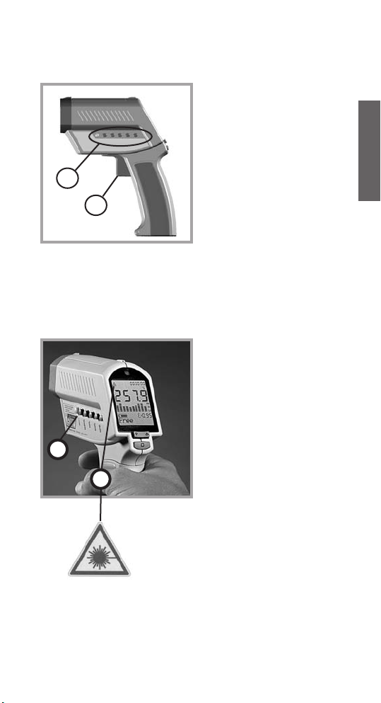
The laser sight simplifies
sighting of the measurement object. It shows the
spot size that includes the
measured target.
To turn the laser on or off
press the LASER button
(K) when the trigger is
pulled. A laser symbol (1)
appears when the laser is
on. The laser automatically
turns off if you release the
trigger.
7
english
To select a function, first
turn the unit on by pulling
the trigger (F). Then push
the button of the desired
function (H). To change
functions, press ENTER
or the function button
again, and then the new
function button.
SELECTING
A FUNCTION
LASER
ON/OFF
H
F
laser ON
symbol
K
1
Page 12
8
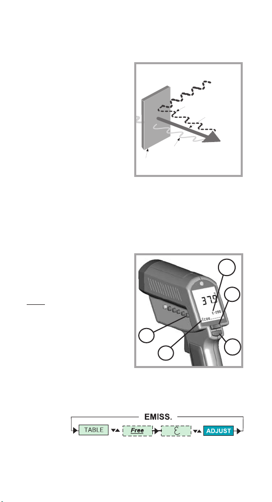
The amount of infrared
energy radiated by an
object depends on its
emissivity and its
temperature.
The emissivity depends on
the material and its surface
characteristics. For more
accurate readings, adjust
the emissivity value for
the type of material being
measured.
EMISSIVITY
EMISSIVITY EXPLAINED
To adjust the emissivity
value, press EMISS (P).
Use the Up and Down
keys to select “Free“
(“F
ree” will have a
flashing underline) (7).
Press EMISS again.
“Free” is not underlined,
and the emissivity icon (5)
flashes. Use the Up and
Down keys (C) to adjust.
Press ENTER (D) to
activate this setting.
EMISSIVITY
ADJUST EMISSIVITY
P
5
7
C
D
Target
Transmitted energy
Reflected energy
Emitted energy
EMISSIVITY
Page 13

To adjust the unit’s
emissivity value for a
material with unknown
emissivity, plug in the
probe.
Pull the unit’s trigger.
Place the measuring
tip of the probe on the
area to be measured.
Wait for the reading to
stabilize.
EMISSIVITY
TABLE OF VALUES
To choose the emissivity
of a material, press
EMISS (P). The display
shows a material name
(7), an emissivity value,
and the calculated
temperature value (5). To
choose another material,
use the Up and Down
keys (C). Press ENTER
(D) to activate this setting.
EMISSIVITY
UNKNOWN VALUE
Note the indicated probe temperature reading.
Release the trigger. Pull the trigger again. Measure
the same area using infrared measurement. Press
the emissivity button (P). Use the Up and Down keys
(C) to select the material name “Free” which will be
shown in the display (7). Press the emissivity button
(P) again until the emissivity sign (5) flashes. Use
the arrow keys (C) to change the emissivity value
until the temperature matches the probe’s reading.
9
english
P
7
5
C
D
Page 14

O
10
To activate the MAX mode,
press MODE (O) until the
MAX symbol appears (9).
The measured maximum
temperature is displayed
(3) as long as the trigger
is pulled or locked on. The
real time temperature is
shown in the lower part of
the display (NORM) (7).
MODE
MAXIMUM
To activate the MIN mode,
press MODE (O) until the
MIN symbol (9) appears.
The measured minimum
temperature (3) is
displayed as long as the
trigger is pulled or locked
on.
The real time temperature
is shown in the lower part
of the display (NORM) (7).
MODE
MINIMUM
O
9
3
7
MAX
9
3
7
MIN
Page 15
O
3
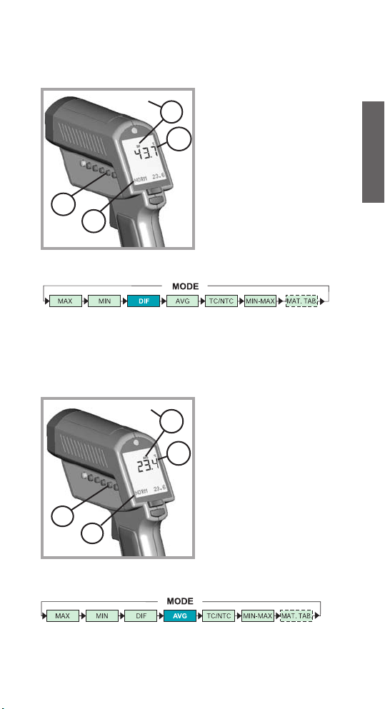
11
english
MODE
DIFFERENCE
To activate the DIF mode,
press MODE (O) until the
DIF symbol (9) appears.
The difference between
the measured max and
min temperatures is
displayed (3) as long as
the trigger is pulled or
locked on. The real time
temperature is shown in
the lower part of the
display (NORM) (7).
MODE
AVERAGE
To activate the AVG mode,
press MODE (O) until the
AVG symbol (9) appears.
The average value of
measured temperatures
(3) is displayed as long
as the trigger is pulled or
locked on. The real time
temperature is shown in
the lower part of the
display (NORM) (7).
O
9
7
DIF
3
7
AVG
9
Page 16
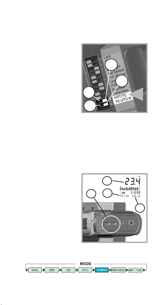
12
10
11
12
Open the battery compartment and set the switches
ON or Off according to the
desired probe type.
(10) NTC - thermistor
(11) TC - thermocouple
(12) Thermocouple type J
(13) Thermocouple type K
MODE TC/NTC
PROBE
CONNECTIONS
Connect the probe to the
input (U). Press MODE,
until the desired probe
symbol (7) appears. The
probe temperature is
shown in the lower part of
the display (6). The real
time infrared temperature
is shown in the main
display (3).
13
U
7
6
3
Page 17

13
english
SETUP
HIGH ALARM
The high alarm (HiAl)
generates an audible and
visual (flashing LED (A)
and laser) alarm if the
temperature is above the
setpoint.
To set the alarm value (6),
Press SETUP (N) once,
and use the Up and Down
keys (C).
Then press ENTER (D)
to activate this setpoint.
N
A
6
C
D
The low alarm (LoAl)
generates an audible and
visual (flashing LED (A)
and laser) alarm if the
temperature is below the
setpoint. To set the alarm
value (6), Press SETUP
(N) twice and use the Up
and Down keys (C).
Then press ENTER (D)
to activate this setpoint.
SETUP
LOW ALARM
N
A
6
D
C
Page 18
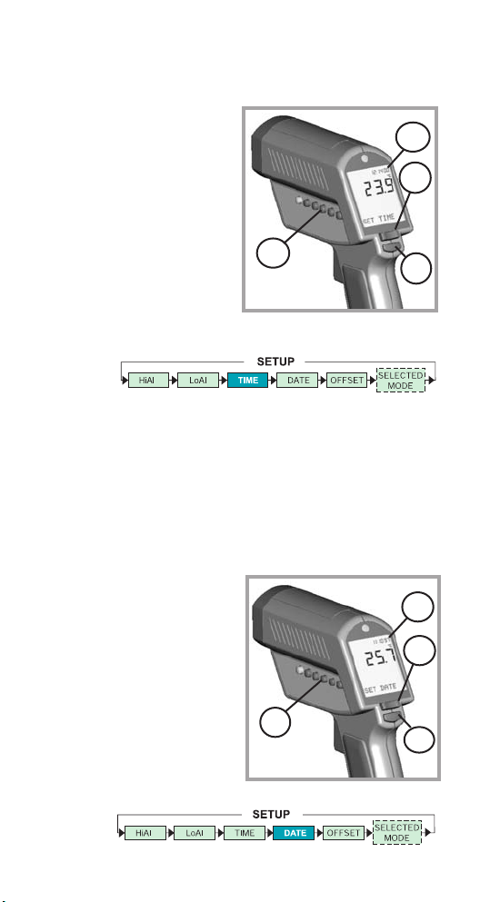
N
14
To set the time, press
SETUP (N) three times.
Change the time (2)
using the Up and Down
keys (C).
Then press ENTER (D)
for each time segment to
activate this time setting.
The time appears on the
display, is stored within
the data logger, and is
part of the printer output.
SETUP
TIME
SETUP
DATE
To set the date, press
SETUP (N) four times.
Change the date using the
Up and Down keys (C).
Then press ENTER (D)
for each date segment to
activate this date setting.
The date (2) is stored
within the data logger
and is part of the printer
output.
N
2
C
2
D
C
D
Page 19

SETUP
OFFSET
This function is used with a
selected emissivity to add
or subtract an offset value
(±10°C/±18°F) to the
temperature value. Press
the Setup button (N) until
"Offset" appears in the
display. With the arrow
keys (C) adjust the display
to the corrected value.
Press ENTER (D) to
confirm. If OFFSET is used, a symbol (1) appears in
the display. The OFFSET feature allows the
temperature values for several units to be matched,
correcting for the allowed temperature tolerance
difference between units. The OFFSET function can
also be used to increase the accuracy for a narrow
temperature range.
15
english
N
1
D
C
MODE
MIN-MAX VALUES
To show the minimum
and maximum
temperature values during
a measurement at the
bottom of the display,
press MODE (O) until the
two values appear (6).
O
6
MODE
MAX MIN DIF AVG TC/NTC MIN-MAX
Page 20

16
DATA LOGGER
HOW TO STORE DATA
To Recall stored data,
press the ENTER button
(D), without pulling the
trigger. Then press the
DATA button (M) until RCL
appears on the display. A
log location will be shown
(6).
To select another log location, use the Up and Down
keys (C).
DATA
RECALL
M
6
D
C
By pressing the ENTER
button (D) the LOG
function (6) appears on
the display. Pull the trigger
(F) and hold it. Aim at the
target. Be sure that the
laser sighting is inside
the target. Gently release
the trigger to record the
temperature. The next
location will be shown
on the display.
This function is also initiated by pressing the DATA
button (M) once.
D
6
F
M
Page 21

17
english
The graphic display (4)
shows the temperature as
a picture. The last ten
measurements are shown
(B). It is possible to choose
between Auto Range and
Manual Range. In manual
range the user defines the
beginning and ending
temperature points of the
graph.
DISPLAY
GRAPHIC DISPLAY
DISPLAY
AUTO OR MAN RANGE
Press DISPLAY (L) once.
Use the Up and Down
keys (C) to toggle between
ranges. Auto Range is
automatically defined by
the measured maximum
and minimum value.
Manual Range (Man
Range) is user defined
(see DISPLAY, BEGIN
section).
B
L
C
4
Page 22

18
To set the BEGIN value
for the graphic display
(Man Range is activated),
press DISPLAY (L) until
“Begin” is shown at the
status bar. Use the Up
and Down keys (C) to
select the value (6).
DISPLAY
BEGIN
(Man. Range)
DISPLAY
END
(Man. Range)
To set the END value of
the graphic display (Man.
Range), press DISPLAY
(L) until ”End” is shown at
the status bar. Use the Up
and Down keys (C) to
select the value (6).
L
C
6
L
C
6
Page 23
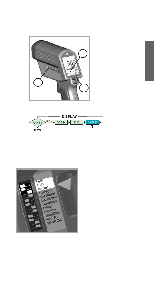
19
english
CYCLE allows the
adjustment of the
display interval.
Press DISPLAY (L)
until Cycl.: (7) is
shown at the status
bar. To select the
interval time, use the
Up and Down keys
(C). The default value
is pre-set for 0.2 sec.
DISPLAY
CYCLE
Change the setting in the
unit by using the DIP
switches located in the
battery compartment (see
BATTERIES section).
Lock: Trigger locked
(on) or
unlocked (off).
°C/°F: changes between
°C and °F and
date and time
format.
Buzzer: Audible alarm
On or Off.
SETTINGS
(PART 1)
L
C
7
Page 24

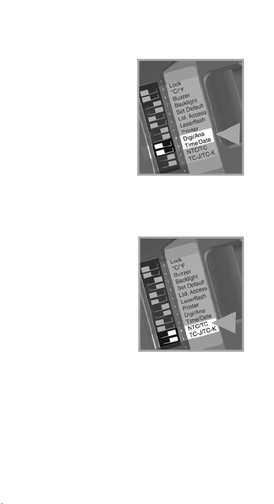
20
Lock
C/ F
Digi/Ana
Laserflash
Ltd. Access
Set Default
Backlight
Buzzer
TC-J/TC-K
NTC/TC
Time/Date
Printer
ON
ON
Lock
Digi/Ana
Laserflash
Ltd. Access
Set Default
Backlight
Buzzer
TC-J/TC-K
NTC/TC
Time/Date
Printer
C/ F
Factory Defaults
DIP-Switch Settings
Celsius setting shown
Fahrenheit setting shown
SETTINGS
(PART 2)
Backlight: Backlight On or Off.
Set Default: Activates the factory defaults
by overwriting listed settings
(see specifications).
Ltd. Access: No function buttons will work.
Laserflash: The laser flashes in case of
over- or underranging of the
alarm values.
Page 25

21
english
Printer: (ON) The printer’s data output
(RS232) is working as long as the trigger
is pulled. The protocol includes:
(14) Date
(15) Time
(16) Target temperature - infrared
(17) Target temperature- probe "X"
See software manual for other printout
options.
15
14
17
16
SETTINGS
(PART 3)
PRINTER
Page 26
22
Digi/Ana:
Digital or Analog output.
Digital (RS232) output
must be used with the
printer or a PC. Analog
output (mV/°) is usually
used for data logging.
Time/Date:
Time or date shown on
the display.
SETTINGS
(PART 4)
SETTINGS
(PART 5)
CONTACT PROBES
NTC/TC:
Thermistor (NTC) or
thermocouple (TC).
TC-J/TC-K:
Type of thermocouples.
The temperature range
for the probes:
K: -30°C to 400°C
(-25°F to 750°F)
J : -30°C to 650°C
(-25°F to 1200°F)
NTC: -30°C to 120°C
(-25°F to 250°F)
Note:
The temperature ranges
given are for the unit’s
optional type K
thermocouple.
Page 27
23
english
The measured spot size depends on the distance
between the object you are measuring and the infrared
thermometer. The relationship between distance and
spot size is 50:1 at the focus point. The D:S in the far
field is 12:1.
The best distance between sensor and object is from
10 cm (4“) up to 50 cm (20“).
APPENDIX A
SPECIAL ORDER MODELS
Close-Focus Model
Sub-Zero Model
Temperature Range: -50 to 500°C (-58 to 932°F)
Following is the accuracy table for the
sub-zero model when the ambient temperature
is 25°C (77°F) ±5°C (9°F):
T
arget Temperature Accuracy
-5 to 500°C (23 to 932°F) ±1% of reading or
±1°C (2°F),
whichever is greater
-30 to -5°C (-22 to 23°F) ±1.5°C (3°F)
-50 to -30°C (-58 to -22°F) ±2°C (4°F)
CLOSE FOCUS MODEL
Optical Chart
DISTANCE: SENSOR TO OBJECT (IN)
6
0
7.9 9.8
4
2
20
40
18,7
0.75
100
0.62
15,5
150
0.24 IN @ 11.8 IN
0.49
0.37
9,2
12,3
6 mm @ 300 mm
200 250
SPOT DIA. (IN)
1
0.9
22
25
0
50
SPOT DIA. (mm)
DISTANCE: SENSOR TO OBJECT (mm)
FOCUS POINT D:S = 50:1 FAR FIELD D:S = 12:1
0.93
23
500
2.81
Close Focus
70
1000
Page 28

24
TROUBLESHOOTING
Code Problem Action
-O- Target temperature is over Select target
or
within unit’s
-U- under range specs
EEPROM-Err EEPROM error Contact
Factory
CalAreaErr calibration errors Contact
ProbCalEr Factory
Battery icon Battery is low Replace
flashes or Batteries
LowBatt
Blank display Battery is dead Replace
Batteries
Laser won’t Low or dead battery Replace
work Batteries
Ambient above 45
o
C (113oF) Operate
unit in
45
o
C
(113
o
F)
ambient or
below
Display “ON” Display locked “ON” Disconnect
the unit from
the PC or
power
supply
APPENDIX B
TROUBLESHOOTING
Page 29
25
english
APPENDIX C
MAINTENANCE
Lens Cleaning: Blow off
loose particles using clean
compressed air. Brush
remaining debris away with
a camel’s hair brush. Wipe
the surface with a moist
cotton swab. The swab
may be moistened with
water or a water based
glass cleaner.
NOTE: DO NOT use
solvents to clean the
plastic lens.
Cleaning the Housing: To
clean the exterior housing,
use soap and water or a
mild commercial cleaner.
Wipe with a damp sponge
or soft rag.
Page 30
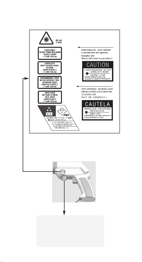
26
CAUTION! Do not stare into beam!
Avoid indirect exposure via
reflective materials!
APPENDIX D
LASER WARNING LABEL
SERIAL NUMBER LABEL
Manufacturer,
Address
Made in Germany: Month, Year
Model: XXXXXXX
Serial: 000000-0000-0000
Power Requirements 3 V
Page 31
english
27
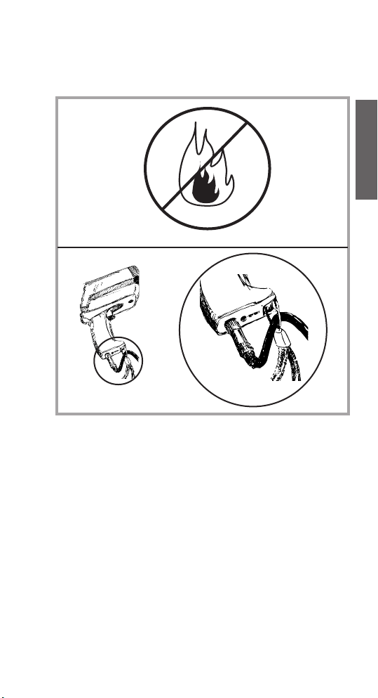
Avoid static electricity, arc welders, and induction
heaters. Keep away from very strong EMF
(electromagnetic fields). Don’t leave the unit
on or near objects of high temperature.
WARNING: DO NOT touch live voltage with
contact probe. Use the wrist strap for cable
support.
APPENDIX E
CAUTIONS
Page 32

28
Avoid abrupt changes in temperature.
If this occurs, allow 40 minutes for
thermal stabilization before use to
prevent the possibility of inaccurate
temperature readings. Use only the power
supply from the manufacturer.
APPENDIX E
CAUTIONS (cont.)
Thermal Shock
Page 33

29
english
APPENDIX F
EMISSIVITIES
Aluminum* 0.30
Asbestos 0.95
Asphalt 0.95
Basalt 0.70
Brass* 0.50
Brick 0.90
Carbon 0.85
Ceramic 0.95
Concrete 0.95
Copper* 0.95
Dirt 0.94
Frozen food 0.90
Hot food 0.93
Glass (plate) 0.85
Ice 0.98
Iron* 0.70
Lead* 0.50
Limestone 0.98
Oil 0.94
Paint 0.93
Paper 0.95
Plastic** 0.95
Rubber 0.95
Sand 0.90
Skin 0.98
Snow 0.90
Steel* 0.80
Textiles 0.94
Water 0.93
Wood*** 0.94
* oxidized
** opaque, over 20 mils
***natural
Page 34

SPECIFICATIONS
Temperature Range - 30 to 900°C (- 25 to 1600°F)
Display Resolution 0.1°C (0.2°F)
Accuracy ± 0.75% of reading or
(Infrared) ± 0.75K (± 1,5°F), whichever is greater
at 25°C (77°F) ambient temperature,
± 2K (± 4°F) for targets
below -5°C (23°F)
Ambient derating < 0.05K/K or < 0.05%/K,
whichever is greater at
+ 25°C (77°F) ± 25K (± 45°F)
Optical Resolution 60:1 (19mm spot size at 1.15 M.)
(Standard Focus) (0.75in. spot size at 3.8 feet)
Optical Resolution 50:1( 6mm spot size at 0.3 M.)
(Close Focus) (0.24in. spot size at 0.98 feet)
Accuracy ± 2K or ± 0.75%,
(Thermocouple K & J) whichever is greater
Accuracy
(Thermistor)
-30 to 0°C (-22 to 32°F) ± 0.6K
0 to 70°C (32 to 158°F) ± 0.4K
70 to 100°C (158 to 212°F) ± 1K
100 to 120°C (212 to 248°F) ± 1.5K
Repeatability ± 0.5% of reading or ± 0.5°C (1°F),
(Infrared) whichever is greater,
± 1°C (± 2°F) for targets
below -5°C (23°F)
Response Time (95%) 250 mSec
Hot Spot Detection (30%) 85 mSec
Spectral Range 8 to 14 µm
Ambient Operating Range 0 to 50°C (32 to 122°F)
Storage Temperature -20 to 50°C (-4 to 122°F)
(without batteries)
Analog output 1 mV/°C(°F)
Digital Output RS232
30
Page 35

english
31
FACTORY DEFAULTS
Default Range
Emissivity/Gain 0.95 0.10 to 1.50
in steps of 0.01
Emissivity Table Free 30 materials
Mode normal
Hi Alarm 50°C (100°F) -30 to 900°C
(-25 to 1600°F)
Lo Alarm 0°C (32°F) -30 to 900°C
(-25 to 1600°F)
Offset Adjust 0°C (0°F) -10 to 10°C
(-18 to 18°F)
Graphic Display Auto Range Auto Range
/ Man Range
Cycle Time 0.2 sec 0.1 sec to 300 sec
Printer Mode Data Recording 3 modes,
selectable
via software
Printer output ASCII
8 bits
1 Stop bit
No Parity
Baud Rate 9600
Data logger 100 points
pre-set with emissivity 0.95
Lo-Al: 0°C
Hi-Al: 50°C
adjustable only via Software
Accessory
SPECIFICATIONS (Cont.)
Power 2 x 1.5 V Alkaline Type AA
Battery Life 13 hrs. (50% laser and 50% backlight on)
Power supply 7.5 V
>
200 mA (Using the power supply
(External) the display automatically switches on)
Dimensions 200 x 170 x 50 mm (7.9 x 6.7 x 2 inches)
Tripod Mount 1/4”-20 UNC
Page 36

32
This instrument conforms to the following
standards:
EMC: - EN 61326-1
Safety: - EN 61010-1:1993 / A2:1995
- EN 60825-1:1994
This product herewith complies with the
requirements of the EMC Directive
89/336/EEC and the Low Voltage
Directive 73/23/EEC.
This instrument conforms to the Standards
of the European Community.
CE CONFORMITY
NIST/DKD
CERTIFICATION
The temperature sources used to calibrate this
instrument are traceable to the U.S. National
Institute of Standards and Technology (NIST)
and the Deutscher Kalibrierdienst (DKD). NIST
and DKD certificates are available as an option
from the manufacturer.
Page 37

Infrared Thermometer with LinTech* Bluetooth module
This infrared thermometer allows wireless data transfer with the aid of Bluetooth technology.
System requirements:
- Windows-compatible computer (operating system 98, ME, 2000, XP or higher)
- Bluetooth system fully installed on the computer (not included)
- BlueTool configuration software (included)
After the Bluetooth system has been installed as required on the computer, the thermometer can be operated in two
different modes:
1. Passive mode
In this mode, the thermometer is constantly activated
and is searched for by the computer. This is advantageous when continuous temperature monitoring
should take place.
Attention: As a result of continuous operation, the thermometer‘s
batteries are discharged much faster then during intermittent use.
Proceed as follows:
1. Switch on the thermometer with the measurement
button.
2. Press the Setup
button on the display.
The words “Bluetooth on-up,
off-down“ appear. Activate
Bluetooth with the Up button
below the display. A lightning
symbol in the display
indicates that the Bluetooth
module is ready
- the lock symbol signals continuous operation.
Note: If the automatic battery test finds that the battery is too weak
here (display: “LowBat - no BT“), the Bluetooth application is not
started.
* Please refer to the LinTech specifications overview for the exact specification of the Bluetooth module used.
3. Now start the Bluetooth software on your computer
and allow it to search for and
connect the Bluetooth devices.
(Please refer to the relevant operating
instructions for how this happens in the
case of your Bluetooth application)
4. The thermometer is reco-
gnized as “IR Therm....“. The
requested PIN is “1234“ when
the unit is delivered. With the
right mouse button, click on the
symbol for the device and select
“Eigenschaften/Properties“ in
the submenu. Make a note of
the ComPort‘s number. The
green LED on the left above the
thermometer‘s display signals
the existing connection.
5. If you have not already done
so, now start the relevant
application software for the
thermometer. Before you can exchange data between
the thermometer and computer, you must set in this
software the number of the ComPort found under Point 4.
6. Press the Setup button
and then the Down button
below the display to end the
Bluetooth connection.
If data is being
transferred at this time,
you cannot deactivate
the Bluetooth module.
Important note: The above refers to the thermo
meter as delivered. It can be programmed on a
user-defined basis with the aid of the “BlueTool“
software. For details, see the section “User-defined
configuration“.
2. Active mode
After switching on, the thermometer automatically
establishes contact with the computer, the address of
which has been programmed for the thermometer.
This is done by the supplied BlueTool software
details, see the section “User-defined configuration“). The active mode is particularly suitable for
intermittent operation of the infrared thermometer. The
thermometer‘s power consumption is significantly less
than in passive mode.
Making contact with the computer and
data transfer
Open the thermometer‘s handle and switch the DIL
switch 9 to ON (Master). Switch on the thermometer
with the measurement button.
(for
In the display, a framed lightning
symbol points to the Bluetooth
module in active mode and the
thermometer starts to search
for the associated computer.
When the connection has been
made, a green LED lights up
on the left above the display
and the color of the Bluetooth symbol changes on the
connected computer. You can now transfer data to the
thermometer‘s user software.
The thermometer automatically switches itself off after
approximately 7 seconds if the measurement button is
not pressed and if there is no data transfer.
3. User-defined configuration
Preparing the thermometer
Open the device‘s handle and set the DIL switch 5 to
ON (Set Default). “Default ?“
appears in the display. At this
point in time, it is essential
for the DIL switch 9 to be set
to OFF (Slave). Now start the
Bluetooth module as described under “Passive mode“.
Programming the thermometer with the aid of
BlueTool
Start the Bluetooth software
on your computer and start
the device search. Make the
connection by double clicking on the symbol for the
in-frared thermometer (signaling by the green LED on
the left above the display and the color of the Bluetooth
symbol changes on the computer). The properties can
be displayed by right-clicking on the service under
Page 38

Serial Ports. Note the number of the
connected ComPort.
Now start the BlueTool
application, enter the
ComPort number just
found and then click on
Connect.
A configuration window
opens.
It shows various details of
the device and several fields for calling up additional setting
possibilities.
First open ”Device settings“.
Here you can give the thermometer a name and change
the PIN.
Attention: Be sure to make a note of this PIN, because
you will be asked to provide it for encrypted transmissions
and connections with the aid of the BlueTool software. SPP
must be selected as the ComHardware mode and the connection indicator must be deactivated. Confirm the settings
with OK. Now open ”Master settings“.
Here, place a tick in front
of both “Master - automatic connection attempt“
and “Master attempts to
establish connection when
starting“. The address of the
current computer is in the
Remote BTA field
Note: Only if you wish to address another computer
(e.g. PDA or notebook) with the thermometer later must
you enter the Bluetooth address of the other computer
here. The same applies to the PIN in this window. It is
then binding for the connection with the other computer.
It is therefore essential to note it.
Click on OK. In the main window, first
settings“ - the data is transferred to the thermometer.
With “Update“, you can call up the current settings to
check them.
Then end the program. Now switch the DIL switch 5 in
the thermometer‘s handle back to OFF. Press the DOWN
button under the display. Now wait until the device
switches itself off automatically (approximately 7 s).
click on “Save
FCC NOTICE
This device complies with Part 15 of the FCC Rules.
Operation issubject to the following two conditions:
(1) this device may not cause harmful interference,
and
(2) this device must accept any interference received, including interference that may cause undesired
operation.
NOTE: This equipment has been tested and found
to comply with the limits for a Class A digital device,
pursuant to Part 15 of the FCC Rules. These limits are
designed to provide reasonable protection against
harmful interference when the equipment is operated
in a commercial environment. This equipment generates, uses, and can radiate radio frequency energy
and, if not installed and used in accordance with the
instruction manual, may cause harmful interference to
radio communications. Operation of this equipment in
a residential area is likely to cause harmful interference
in which case the user will be required to correct the
interference at his own expense.
WARNING: Modifications not expressly approved by
this company could void the user‘s authority to operate the equipment.
FCC ID: STG-DFQMX4.
 Loading...