

Page 1
THERMALERT®CI
™
COMPACT INFRARED
SENSOR
OPERATOR’S GUIDE
TWO YEAR LIMITED WARRANTY
Raytek warrants this product to be free from defects in material and
workmanship under normal use and service for a period of two
years from date of purchase except as hereinafter provided. This
warranty extends only to the original purchaser (a purchase from
Raytek or Raytek’s licensed distributors is an original purchase).
This warranty shall not apply to fuses or batteries. Factory calibration is warranted for a period of one year. The warranty shall not
apply to any product which has been subject to misuse, neglect,
accident, or abnormal conditions of operation or storage. Should
Raytek be unable to repair or replace the product within a reasonable amount of time, purchaser’s exclusive remedy shall be a refund
of the purchase price upon return of the product.
In the event of failure of a product covered by this warranty, Raytek
will repair the instrument when it is returned by the purchaser,
freight prepaid, to an authorized Service Facility within the applicable warranty period, provided Raytek’s examination discloses to its
satisfaction that the product was defective. Raytek may, at its
option, replace the product in lieu of repair . With regard to any covered product returned within the applicable warranty period,
repairs or replacement will be made without charge and with return
freight paid by Raytek, unless the failure was caused by misuse,
neglect, accident, or abnormal conditions of operation or storage, in
which case repairs will be billed at a reasonable cost. In such a case,
an estimate will be submitted before work is started, if requested.
THE FOREGOING WARRANTYIS IN LIEU OF ALLOTHER WARRANTIES, EXPRESSED OR IMPLIED, INCLUDING BUT NOT
LIMITED TO ANY IMPLIED WARRANTY OF MERCHANTABILITY, FITNESS, OR ADEQUACY FOR ANYPARTICULAR PURPOSE
OR USE. RAYTEK SHALL NOT BE LIABLE FOR ANY SPECIAL,
INCIDENTAL OR CONSEQUENTIAL DAMAGES, WHETHER IN
CONTRACT, TORT, OR OTHERWISE.
Rev J
05/00
56800-1
Raytek, the Raytek Logo, and Thermalert are registered trademarks and
CI is a trademark of Raytek Corporation
© Copyright 1996-2000 by Raytek Corporation
CI
THERMALERT SERIES
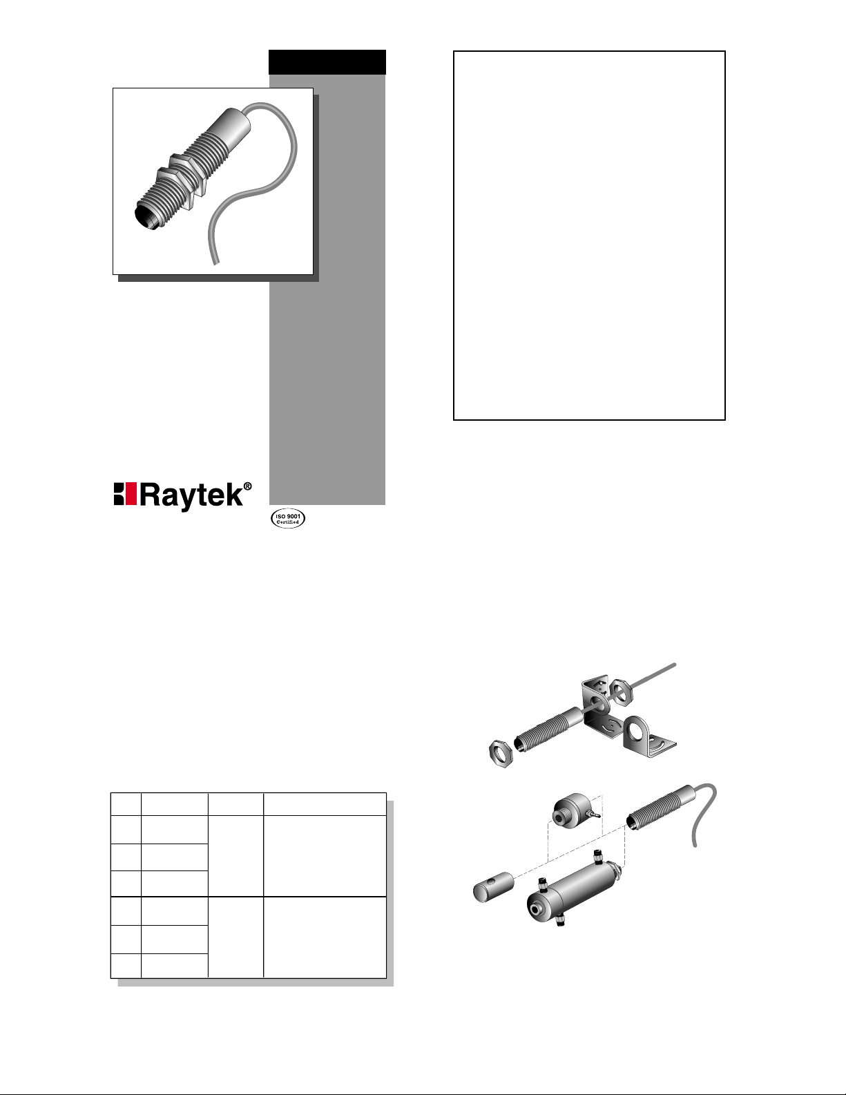
A full range of accessories for various applications and
industrial environments are available (see Figure 1).
Accessories may be ordered at any time and added
on-site. Also available is a J- or K-type thermocouple
connection kit and extension cables.
THERMALERT CI
The Thermalert®CI™Compact Infrared Sensor series
of online instruments are noncontact infrared temperature measurement systems. They are designed to measure accurately and repeatably the amount of heat energy emitted from an object and to convert that energy
into a measurable electrical signal.
Each model (see Table 1) comes with a 1 m (3 ft) cable
and two mounting nuts and is designed for easy integration into standard 4-wire systems. There are J or K
thermocouple output models or 10 mV/°C voltage output models if your application is susceptible to noise or
requires a long cable run. The electronics are protected
by a rugged NEMA 4 stainless steel housing.
2
1
ACCESSORIES
Table 1: Models
Figure 1: Accessories and Options
Model Output Accuracy
J Thermocouple
CI1A
K Thermocouple
CI2A
Voltage
CI3A
J Thermocouple
CI1B
K Thermocouple
CI2B
Voltage
CI3B
Overall
Temp. Range
0 to 350˚ C
(32 to 662˚ F)
30 to 500˚ C
(86 to 932˚F)
0 to 115˚ C (32 to 240˚ F)
larger of ±2% or ± 3˚ C (±6˚ F)
116 to 225˚ C (241 to 440˚ F)
larger of ±5% or ±6˚ C (±10˚ F)
226 to 350˚ C (441 to 662˚ F)
100 to 500˚ C (212 to 932˚ F)
larger of ±2 % or ±3˚ C (±6˚ F)
30 to 99˚ C (86 to 211˚ F)
larger of ±5% or ±6˚ C (±10˚ F)
>±5%
Adjustable mounting
bracket accessory
Fixed
Mounting nuts
(2 supplied)
Sensor
Air purge collar
accessory
Right angle mirror
accessory
Air/Water-cooled housing
mounting bracket
accessory
Sensor
with integrated air purge
(factory installed option)
Page 2
OPTIONS
Options for various applications and environments
are available. Options are factory installed and must
be ordered with base model units. These include the
following:
• NIST traceable certification
• Air/Water-cooled housing (comes with integrated
air purging and high temperature cable)
• High temperature cable–260°C (500°F) maximum
ambient temperature (comes standard with
air/water-cooled housing option)
• Longer 3 m (10 ft) standard cable
3
SPECIFICATIONS
Table 2 (below and continued on Page 4) lists the sensor’s optical, thermal, operational, electrical, environmental, and physical specifications.
Continued on next page
Table 2: Specifications
4
Table 2 (continued): Specifications
65
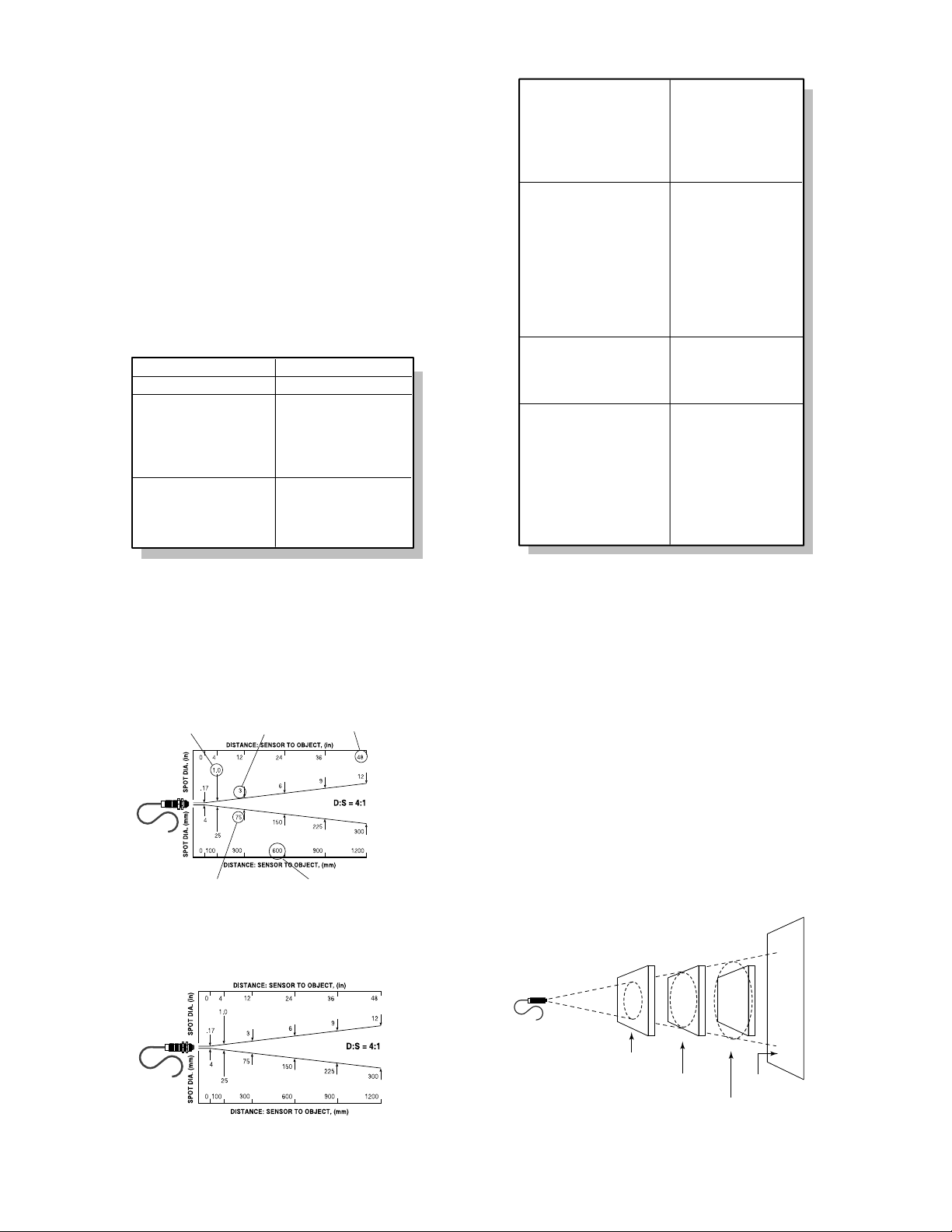
Optical Chart
Figure 2 shows you how to read the optical chart. The
optical chart (Figure 3) indicates the nominal target
spot diameter at any given distance from the sensing
head and assumes 90% energy.
Figure 2: How to Read the Optical Chart
INSTALLATION
The installation process consists of the following:
• Preparation
• Mechanical Installation
• Electrical Installation
The most important part of the installation process is
preparation. Please read the following section thoroughly before proceeding with the mechanical and
electrical installations.
Preparation
Distance and Spot Size—The size of the area (spot
size) you wish to measure determines the distance
between the sensor and the target (see Figure 3 for distances and spot sizes). The spot size must not be larger than the target. Mount the sensor so the measured
spot is the same or smaller than the target. Figure 4 is
an overview of proper sensor placement.
Figure 4: Proper Sensor Placement
Figure 3: Optical Chart
Optical Resolution
Spectral Response Range
Thermal
Measurement range
Detecting element
Accuracy
Repeatability
Temperature coefficient
Operational
Temperature resolution
Emissivity
Response time
Warm-up period
4:1
90% energy
@
7–18 µm
See Table 1
Thermopile
See Table 1
±1% of reading
0.2˚ C per ˚C (0.2˚ F per ˚F)
< 0.5˚ C (1˚ F)
Fixed at 0.95
350 mSec (95% response)
< 1 minute
Electrical
Power supply voltage
Maximum current draw
Ripple
Output impedance
Minimum load impedance
Outputs
Environmental
Sensing head rating
EMI
Conducted noise immunity
Relative humidity
Storage temp. range
Thermal shock
Ambient operating range
air cooling
water cooling
water cooling/high temp cable
Physical
Dimensions
Weight
Material
Cable–Standard
Maximum ambient temperature
Material (type & color)
Cable length
Gauge
Cable–High Temperature
Maximum ambient temperature
Material (type & color)
Cable length
Gauge
12 – 24 VDC @20 mA
≤ 10 mA
≤ 2.5%
50 ohms
50K ohms
J or K thermocouple,
10mV/˚C Linear Voltage
IP 65, NEMA 4
IEC 801-4, Level 1
10 to 95%, non-condensing
-30 to 85˚ C (-22 to 185˚ F)
Max error of 5˚ C (for ∆T=25˚)
stabilization time=20 mins.
0 to 70˚ C (32 to 160˚ F)
0 to 94˚ C (32 to 200˚ F)
0 to 105˚ C (32 to 220˚ F)
0 to 260˚ C (32 to 500˚ F)
19 mm dia x 87 mm L
(0.75 in dia x 3.4 in L)
130 g (4.5 oz)
Stainless steel
105˚ C (220˚ F)
PVC, grey
1 m (3 ft)
AWG 24 (J, K t/c cable)
AWG 22 (10mV/˚C cable)
260˚ C (500˚ F)
Teflon, black
1 m (3 ft)
AWG 24
Target spot size
at focus point
Diameter of target
spot size in millimeters
Focus Point D:S = Distance to spot divided by spot diameter at the focus point
Far Field D:S = Ratio at distances greater than 10x the focus distance
Diameter of target
spot size in inches
Distance from sensor to
object in millimeters or meters
Distance from sensor
to object in inches or feet
GoodBest Incorrect
Sensor
Target greater
than spot size
Target equal
to spot size
Background
Target smaller
than spot size
Page 3

Ambient Temperature—The sensing head is designed
to operate in ambient temperatures from 0 to 70°C (32
to 160°F). For ambient temperatures above 70°C
(160°F), a factory installed air/water-cooled housing
option is available that allows operation in ambient
conditions up to 260°C (500°F) with water cooling.
The air/water-cooled housing option comes with a
high-temperature cable and integrated air purging.
Atmospheric Quality—Smoke, fumes, dust, and other
contaminants can coat the lens and cause erroneous
temperature readings. We recommend using the air
purge collar accessory in these types of environments
to keep the lens clean. (The air/water-cooled housing
comes with integrated air purging.)
Electrical Interference—To minimize electrical or electromagnetic interference or “noise,” mount the sensor
away from motors producing large step load changes.
Wiring—Before installing, be sure to check the distance between the sensor and the monitoring/controlling device. If necessary, extension cables are available
as accessories.
Power—Have available a 12–24 VDC, 10 mA, power
supply.
Mechanical Installation
All sensors come with a 1 m (3 ft) cable and 2 mounting nuts. You can mount the sensor in brackets or
cutouts of your own design, or you can use the fixed
and adjustable mounting bracket accessories. Figures
5 through 7 show the mounting bracket accessories’
and sensor’s dimensions.
8
7
Figure 5: Fixed Mounting Bracket
Air/Water-cooled Housing with integrated air purge—
The air/water-cooled housing option (Figure 8) allows
the sensor to withstand ambient temperatures up to
260° C (500° F) with water cooling and the high-temperature cable. (The high-temp cable is standard when the
housing is ordered as an option.) It has 1/8” NPT fittings for water and air. Water temperature should be
15-30° C (60-86° F) for best performance. Chilled water
below 10° C (50° F) is not recommended. Without the
high-temperature cable, the sensor can withstand ambient
temperatures only up to 105° C (220° F) with water cooling.
9 10
Figure 8: Air/Water-cooled Housing
Figure 6: Adjustable Mounting Bracket
Figure 7: Sensor
Full R
∅19 (.76)
38
(1.5)
(.75)
22
(.875)
∅5 (.196)
38
(1.5)
19
mm (inches)
2X 90˚
1.5
(.06)
2X 45˚
(.196)
2X 13
(2X .5)
38
(1.5)
5
38
(1.5)
∅19 (.76)
Full R
41
(1.625)
(1.5)
38
(.875)
22
2X 90˚
59
(2.31)
2X 45˚
(.196)
2X 13
(2X .5)
5
1 m (3 ft)
PVC Cable
∅4 (.17)
∅17 (.67)
(.75)
19
(3.5)
(2.48)
89
63
3/4"–16UNF 2A
M18 x 1 (if ordered metric)
19
(.75)
38
(1.5)
mm (inches)
∅14 (.56) ∅19 (.75)
(.27)
mm (inches)
∅5 (.196)
(1.5)
38
∅38 (1.5)
∅20 (0.8)
~ 25
(~ 1)
Rear View
96
(3.79)
1/8" NPT fittings (3)
118
(4.63)
137
(5.38)
Front View
10
(0.39)
7
6
(0.25)
25
(1)
∅38 (1.5)
3/4"–16UNF 2A
13
flats
(0.5)
(0.45)
~ 13
(~ 0.5)
mm (inches)
12
Page 4

11
Air Purge Collar—The air purge collar accessory
(Figure 9) is used to keep dust, moisture, and other
contaminants away from the lens. It must be screwed
in fully. Air flows into the 10/32” fitting and out the
front aperture. Clean or “instrument” air is recommended. The air purge collar accessory is not needed with
the air/water-cooled housing.
Figure 9: Air Purge Collar
Table 3: Recommended Water and Air
12
Right Angle Mirror—The right angle mirror accessory
(Figure 10) allows a perpendicular view of a target. It
may be used when space is limited or when you need
to avoid excessive radiation to the sensor. This can be
mounted either on the end of the sensor or on the air
purge collar, but not on the air/water-cooled housing.
Note: When using the right angle mirror, a small
amount of energy emitted by the source is lost, which
results in a lower than actual temperature reading. To
compute the corrected temperature, use this formula:
T = 1.035T
m – .035Tamb
where T=corrected temperature, Tm=temperature reading with mirror, and Tamb=ambient temperature. All
temperatures are in either °C or °F.
Figure 10: Right Angle Mirror
13
WARNING
Incorrect wiring will cause severe, per-
manent damage to the sensor.
Pay close attention to the wiring diagram in
Figure 11, and match your sensor to the appropriate output type in Table 4 or 5. Wire accordingly.
DO NOT CONFUSE OUTPUT WIRES WITH
POWER SUPPLY WIRES.
Electrical Installation
Sensor to Electronics Cable—The sensor to electron-
ics cable is a 1m (3 ft), 4-wire, PVC cable. One end is
attached, at the factory, to the sensor head. The
other end has two pairs of wires and a bare shield
(ground) wire (see Figure 11).
The unlabeled pair of wires is for connecting to a
controller or chart recorder or for attaching to a thermocouple plug (for connecting to a thermocouple
meter). DO NOT CONNECT TO APOWER
SOURCE.
The second pair of wires, with the label, is for connecting to a power source.
14
Figure 11: Wiring Configuration
Table 4: Standard Cable Wiring
Wiring—Wire the electronics cable using Figure 11 and
Table 4 or 5 (for high temp cables) as a guide. USE
ONLY THE OUTPUT TYPE OF YOUR SENSOR.
WIRING TO THE WRONG OUTPUT WILL DAMAGE THE SENSOR. Note in Figure 11 that the num-
bers refer to the wire numbers in Table 4 or 5, which
shows proper wiring connections based on insulation
color coding.
Inside threads M18 x 1
(if ordered with metric threaded sensor)
3/4" – 16UNF 2A
35
(1.36)
(0.42)
11
(0.84)
9
(0.37)
21
31
(1.21)
mm (inches)
∅19 (0.75)
10/32" threads
∅35
(1.38)
~ 25
(~ 1)
(2.38)
61
Recommended
Cooling water supply
Temperature
Flow rate
Pressure drop
Cooling air supply
Temperature
Flow rate
Pressure drop
Air purge air supply
Temperature
Flow rate
Pressure drop
(across unit only)
(across unit only)
(across unit only)
15–30˚ C (60–86˚ F)
1.89 liters per min (0.5 gpm)
< 0.69 bar (10 psi)
< 30˚ C (< 86˚ F)
70.8 liters per minute (2.5 SCFM)
< 0.34 bar (5 psi)
< 30˚ C (< 86˚ F)
11.33 liters per minute (0.4 SCFM)
< 0.34 bar (5 psi)
∅20 (.8)
3/4"–16 UNF 2B
82
13
(.5)
20
(.8)
31
(1.25)
mm (inches)
NOTE LABEL
(ON POWER
SUPPLY WIRES ONLY)
Wire Numbers
(Refer to Table 4 or 5)
12 – 24 VDC Red (+)
1
2
3
4
5 (Shield)
J-type
Thermocouple
K-type
Thermocouple
10mV/˚C
Voltage
Output
Power
Supply
–
Output
Power
Supply
–
Output
Power
Supply
–
Wire
Number
1
2
3
4
5
1
2
3
4
5
1
2
3
4
5
White
Red (white stripe)
Red (yellow stripe)
Yellow
Bare
Yellow
Red (yellow stripe)
Red (white stripe)
White
Bare
White
Green
Red
Black
Bare
FunctionWire ColorOutput Label
Signal + (Iron)
Signal – (Constantan)
Power Supply +
Power Supply –
Shield Ground
Signal + (Chromel)
Signal – (Alumel)
Power Supply +
Power Supply –
Shield Ground
Signal +
Signal Ground
Power Supply +
Power Supply –
Shield Ground
Page 5

Extension Cables—Extension cables are available as
accessories. Also available is a thermocouple connection kit.
MAINTENANCE AND
TROUBLESHOOTING
If your sensor is not performing as it should, try to
match the symptom in Table 6 to its probable cause. If
the table does not help, call us at one of the phone
numbers listed on the last page.
Our customer service representatives are always at
your disposal for application assistance, calibration,
repair, and solutions to specific questions or problems.
Contact our Service Department before returning any
equipment to us. In many cases, problems can be
solved over the telephone.
IMPORTANT
Be aware of the following when using the sensor:
• If the sensor is exposed to significant changes in
ambient temperature (hot to cold or cold to hot),
allow 20 minutes for the temperature to stabilize
before taking or recording measurements.
• Do not operate the sensor near large electrical or
magnetic fields (e.g., around arc welders or induction heaters). Electro-Magnetic Interference (EMI)
can cause measurement errors.
• Connectors or wires must be connected only to the
appropriate input jacks or terminals.
16
15
OPERATION
Once the sensor is in position and you have made sure
that the appropriate power, air, water, and cable connections are secure, the system is ready for continuous
operation.
To operate, complete the following simple steps:
1. Turn on the power supply.
2. Turn on the meter, chart recorder, or controller.
3. Read/monitor the temperature.
WARNING
If using the air/water-cooled housing, do not
leave it in a heated environment with the
coolant turned off. Damage to the sensor and to
the housing can occur.
Table 5: High Temperature Cable Wiring
Raytek Corporation
Worldwide Headquarters
Box 1820, Santa Cruz, CA 95061-1820
Phone: (831) 458-1110 (800) 227-8074
FAX: (831) 458-1239
Raytek GmbH
European Headquarters
Phone: 49 30 478 0080
FAX: 49 30 471 0251
Raytek do Brasil
South American Headquarters
Phone: 55 15 233 6338
FAX: 55 15 233 6826
Raytek Mexico
Mexico, Caribbean, and Central America
Phone: 52 22 30 4380
FAX: 52 22 30 4438
Raytek Japan, Inc.
Phone: 81 3 3822 5715
FAX: 81 3 3822 5712
Raytek China Company
Phone: 86 10 6437 0284
FAX: 86 10 6437 0285
Raytek UK Ltd.
Phone: 441 908 630800
FAX: 441 908 630900
Raytek France
Phone: 33 1 64 53 1540
FAX: 33 1 64 53 1544
17
Symptom
No output
Erroneous T emp .
Erroneous T emp .
Erroneous T emp .
Probable Cause
No power to sensor
Incorrect wire
connection
Faulty sensor cable
Field of view
obstruction
Solution
Check the power
supply
Check wire color
codes and reconnect
Verify cable continuity
Remove obstruction
Lens Cleaning—Keep the lens clean at all times. Blow
off loose particles (if not using the air purge accessory)
with clean compressed air, then carefully wipe surface
with moist cotten swab (water or water-based glass
cleaner). DO NOT use solvents.
Table 6: Troubleshooting
CE CONFORMITY FOR THE
EUROPEAN COMMUNITY
This instrument conforms to the following standards:
• EN50081-1:1992, Electromagnetic Emissions
• EN50082-1:1992, Electromagnetic Susceptibility
Emission tests were conducted over a frequency range
of 30–1000 MHz and susceptibility tests over a range
of 27–500 MHz . The instrument’s average error in
these frequency ranges is 1.0° C at an electric field
strength of 3 V/m. At some frequencies the instrument may not meet its stated accuracy.
Wire
Number
J-type
Thermocouple
K-type
Thermocouple
10mV/˚C
Voltage
Output
Power
Supply
Output
Power
Supply
Output
Power
Supply
1
White
2
Red (white stripe)
3
Red
4
Yellow
5
–
–
–
Bare
1
Yellow
2
Red
3
Red (white stripe)
4
White
5
Bare
1
Red
2
Yellow
3
Red (white stripe)
4
White
5
Bare
FunctionWire ColorOutput Label
Signal + (Iron)
Signal – (Constantan)
Power Supply +
Power Supply –
Shield Ground
Signal + (Chromel)
Signal – (Alumel)
Power Supply +
Power Supply –
Shield Ground
Signal +
Signal Ground
Power Supply +
Power Supply –
Shield Ground
 Loading...