

Page 1
Rev H
6/98
56700-1
RAYNGER
®
3i
™
SERIES
OPERATOR’S MANUAL
▲
°F
°C
T
E
S
L
C
R
G
O
L
amb
T
RUN
▲
▼
LOG
DC
OUT
▼
( )
O
L
( )
I
H
RECALL
MODE
•
ACTIVATE
LOCK
•
R
E
S
A
L
SET
Page 2

Page 3

WARRANTY
Raytek warrants each instrument it manufactures to be free from defects in material and workmanship under normal use and service for the period of one year from date of purchase. This
warranty extends only to the original purchaser. This warranty shall not apply to fuses, batteries,
or any product which has been subject to misuse, neglect, accident, or abnormal conditions of
operation.
In the event of failure of a product covered by this warranty, Raytek will repair the instrument
when it is returned to an authorized Service Facility within one year of the original purchase,
provided the warrantor’s examination discloses to its satisfaction that the product was defective.
The warrantor may, at its option, replace the product in lieu of repair. With regard to any instrument returned within one year of the original purchase, said repairs or replacement will be made
without charge. If the failure has been caused by misuse, neglect, accident, or abnormal conditions of operation, repairs will be billed at nominal cost. In such cases, an estimate will be submitted before work is started, if requested.
THE FOREGOING WARRANTY IS IN LIEU OF ALL OTHER WARRANTIES, EXPRESSED
OR IMPLIED, INCLUDING BUT NOT LIMITED TO ANY IMPLIED WARRANTY OF MERCHANTABILITY, FITNESS, OR ADEQUACY FOR ANY PARTICULAR PURPOSE OR USE.
RAYTEK SHALL NOT BE LIABLE FOR ANY SPECIAL, INCIDENTAL, OR CONSEQUENTIAL DAMAGES, WHETHER IN CONTRACT, TORT, OR OTHERWISE.
WORLDWIDE HEADQUARTERS
Raytek Corporation
1201 Shaffer Road, PO Box 1820
Santa Cruz, CA 95061-1820 USA
Portable Products Division
800 866 5478
Phone 408 458 1110
Fax 408 425 4561
WORLD WIDE WEB
www.raytek.com
EUROPEAN HEADQUARTERS
Raytek GmbH
Arkonastrasse 45-49
D-13189 Berlin, Germany
Phone 49 30 478 0080
FAX 49 30 471 0251
Offices worldwide:
BRAZIL
Raytek do Brasil
Sorocaba, Brasil
Phone 55 152 276556
CHINA
Raytek China Company
Beijing, China
Phone 86 10 437 0284
JAPAN
Raytek Japan, Inc.
Tokyo, Japan
Phone 03 5976 1531
MEXICO
Raytek de Mexico
Puebla, Mexico
Phone 52 22 30 4380
UNITED KINGDOM
Raytek UK
Milton Keynes, UK
Phone 44 1 908 630800
® Raytek and Raynger are registered trademarks and 3i is a trademark of Raytek Corporation
© 1997 Copyright Raytek Corporation
Page 4

Page 5

Raynger 3i Series Operator's Manual Table of Contents
TABLE OF CONTENTS
SECTION PAGE
1.0 INTRODUCTION.............................................................................1-1
1.1 DESCRIPTION.......................................................................................................1-1
1.2 INVENTORY..........................................................................................................1-2
1.3 MODEL IDENTIFICATION.................................................................................1-3
2.0 OPERATION ......................................................................................2-1
2.1 QUICK START........................................................................................................2-2
2.2 PRINCIPLES OF OPERATION............................................................................2-3
2.3 YOUR PORTABLE INFRARED THERMOMETER...........................................2-4
2.4 OPERATION AND CONTROLS.........................................................................2-6
2.4.1 Battery/AC Adaptor Installation...................................................................2-6
2.4.2 Control Panel and Display..............................................................................2-7
2.4.3 Control System ...............................................................................................2-10
2.4.3.1 Control Loops ..............................................................................................2-10
2.4.3.2 General Information....................................................................................2-11
2.4.4 RUN Loop—To Measure Temperature .......................................................2-12
2.4.5 LOG Loop—To Measure and Store Temperature......................................2-14
2.4.6 RECALL Loop—To Recall Measured Temperature ..................................2-16
2.4.6.1 RECALL Values from RUN .......................................................................2-16
2.4.6.2 RECALL Values from LOG........................................................................2-17
2.4.7 SETUP Loop—To Setup and Activate Alarms and Features...................2-19
2.4.7.1 SETUP Values for RUN ..............................................................................2-19
2.4.7.2 SETUP Values for LOG...............................................................................2-21
2.5 USING A TRIPOD...............................................................................................2-22
2.6 DATA OUTPUTS .................................................................................................2-23
2.6.1 Digital Output.................................................................................................2-24
2.6.1.1 Data Output—RUN Loop..........................................................................2-24
2.6.1.2 Data Output—SET Loop............................................................................2-25
2.6.1.3 Data Output—LOG Run Loop..................................................................2-26
2.6.1.4 Data Output—LOG SETUP Loop.............................................................2-27
2.6.2 Analog Output................................................................................................2-28
SECTION PAGE
Page 6

Table of Contents Raynger 3i Series Operator's Manual
2.7 SIGHTING SYSTEMS..........................................................................................2-29
2.7.1 Single Laser Sighting .....................................................................................2-31
2.7.2 Dual Laser Sighting........................................................................................2-31
2.7.3 Crossed Laser Sighting..................................................................................2-32
2.7.4 Scope Sighting ................................................................................................2-32
3.0 SPECIFICATIONS ............................................................................3-1
3.1 THERMAL..............................................................................................................3-1
3.2 OPERATIONAL.....................................................................................................3-2
3.3 ELECTRICAL .........................................................................................................3-3
3.4 ENVIRONMENTAL..............................................................................................3-4
3.5 PHYSICAL..............................................................................................................3-4
3.6 DEFAULT VALUES ...............................................................................................3-5
3.7 REGULATORY.......................................................................................................3-6
4.0 MAINTENANCE...............................................................................4-1
4.1 BATTERY REPLACEMENT.................................................................................4-1
4.2 CLEANING ............................................................................................................4-1
4.2.1 Front Window Cleaning..................................................................................4-1
4.2.2 Cleaning the Housing......................................................................................4-2
4.3 LASER MAINTENANCE.....................................................................................4-2
SECTION PAGE
Page 7

Raynger 3i Series Operator's Manual Table of Contents
APPENDIX A: OPTICAL...........................................................................A-1
HOW TO READ THE OPTICAL CHARTS...................................................................A-1
OPTICAL CHARTS ..........................................................................................................A-2
APPENDIX B: OBJECT EMISSIVITY.......................................................B-1
HOW TO DETERMINE OBJECT EMISSIVITY.............................................................B-1
TYPICAL EMISSIVITY VALUES.....................................................................................B-2
APPENDIX C: TROUBLESHOOTING ....................................................C-1
APPENDIX D: OPTIONS AND ACCESSORIES...................................
D-1
APPENDIX E: TRACEABILITY OF
INSTRUMENT CALIBRATION...............................................................E-1
APPENDIX F: CE CONFORMITY FOR THE
EUROPEAN COMMUNITY......................................................................F-1
GLOSSARY OF TERMS
INDEX
Page 8

Table of Contents Raynger 3i Series Operator's Manual
Page 9
Raynger 3i Series Operator’s Manual 1-1
1.0 INTRODUCTION
1.1 DESCRIPTION
The Raynger
®3i™
series of instruments are portable infrared temperature measurement devices. Each model is rugged and easy to use for making fast, noncontact, nondestructive temperature measurements. They can measure operating temperatures of
mechanical, electrical, or production equipment without removing the equipment
from service. They can also measure product temperatures during manufacturing or
storage without contaminating or marring the product. Table 1-1 lists the standard
Raynger 3i models.
Table 1-1: Raynger 3i Models
TEMPERATURE OPTICAL SPECTRAL
MODEL RANGE RESOLUTION RANGE SIGHTING
LTDL2 &
LTDL3
LTSC
LTCL2 &
LTCL3
-30 to 1200°C
(-20 to 2200°F)
-30 to 1200°C
(-20 to 2200°F)
-30 to 1200°C
(-20 to 2200°F)
75:1
75:1
75:1
8-14 µ
8-14 µ
8-14 µ
dual laser
scope
crossed laser
LRSC
LRSCL2
LRL2 &
LRL3
P7DL2 &
P7DL3
G5SC
1MSC
1ML2 &
1ML3
2MSC
2ML2 &
2ML3
-30 to 1200°C
(-20 to 2200°F)
-30 to 1200°C
(-20 to 2200°F)
-30 to 1200°C
(-20 to 2200°F)
10 to 800°C
(50 to 1450°F)
150 to 1800°C
(300 to 3275°F)
600 to 3000°C
(1100 to 5400°F)
600 to 3000°C
(1100 to 5400°F)
200 to 1800°C
(400 to 3275°F)
200 to 1800°C
(400 to 3275°F)
120:1
105:1
120:1
25:1
50:1
180:1
180:1
90:1
90:1
8-14 µ
8-14 µ
8-14 µ
7.9 µ
5.0 µ
1.0 µ
1.0 µ
1.6 µ
1.6 µ
scope
single laser with scope
single laser
dual laser
scope
scope
single laser
scope
single laser
Page 10

1-2 Raynger 3i Series Operator’s Manual
Each model is molded from rugged, high-strength, solvent resistant plastic and is
actuated by a two-stage trigger (second stage is used for data logging only). Each
model has the following:
• High quality optical system
• Infrared detector
• Circuit board assembly with microprocessor
• LCD display with backlighting feature
• Touch-sensitive membrane switches for changing loops and modes
• Battery compartment for four AA batteries
• Power input jack for AC adaptor
• Signal output jack (analog 1mV per degree/digital RS232)
• A rugged, padded pouch for easy carrying
There are four types of laser sighting models:
• Single laser—shows the center of the measurement area.
• Dual laser—shows the spot diameter of the measurement area.
• Crossed laser—the point where the two laser beams cross is the location of the
minimum diameter measurement spot.
• Single laser with scope
1.2 INVENTORY
Your Raynger 3i package contains the following:
• Raynger 3i
• Carrying Case
• Operator’s Manual
• Four (4) AA batteries
• Warranty card
Page 11

Raynger 3i Series Operator’s Manual 1-3
1.3 MODEL IDENTIFICATION
Refer to Table 1-1 for a list of standard models along with their temperature ranges,
optical resolutions, spectral ranges, and sighting systems.
You can determine the exact model number of your unit by looking at the manufacturing label on the underside of the unit. On the label is an area for model designation. The model type is printed in the following format:
XXXYYYZZZZZ
where XXX is an abbreviation of the company name, YYY is the product (or abbreviation of the product name), and ZZZZZ is the model type. (Model type may be four or
five characters long. Refer to Table 1-1 to compare the label to model type.)
Page 12

1-4 Raynger 3i Series Operator’s Manual
Page 13

Raynger 3i Series Operator’s Manual 2-1
2.0 OPERATION
This portion of the manual contains the following sections:
• Quick Start—To use your unit right away, follow the brief instructions on basic
operating procedures in this section.
• Principles of Operation—A short introduction to infrared thermometry.
• Your Portable Infrared Thermometer—Describes and illustrates the thermome-
ter’s control panel, display, and features.
• How to Operate—A detailed user guide that describes each of the operating
modes. It includes descriptions of the RUN, RECALL, SETUP, and Data Logger
loops.
• Data Outputs—How to use the analog and digital (RS232) outputs to connect the
thermometer to a printer, chart recorder, or computer.
WARNING—LASER SAFETY
Models with laser sighting produce visible laser radiation that may be
harmful to the human eye. Be aware of the following:
• Avoid direct exposure of human eyes to laser light. Eye damage
can result.
• Use extreme caution when operating.
• Never point the unit at another person.
• Keep out of the reach of children.
• Refer to the FDA laser label on the unit for specific information.
IMPORTANT
1. If the unit is exposed to significant changes in ambient temperature
(hot to cold or cold to hot), allow 45 minutes for temperature stabilization before taking measurements.
2. Do not operate the unit near large electrical or magnetic fields such
as arc welders and induction heaters. These fields can cause measurement errors.
3. For the short wavelength units (e.g., 2 µm and below)—Avoid taking
temperature measurements in bright sunlight. High levels of ambient light may produce apparently valid high-temperature readings
when no target is in the thermometer’s field-of-view.
Page 14
2-2 Raynger 3i Series Operator’s Manual
RUN
LOG
SET
LOG
HI
RCL
( )
LO
SET
( )
°C °F
T
amb
Page 15
Raynger 3i Series Operator’s Manual 2-3
2.2 PRINCIPLES OF OPERATION
An infrared thermometer and the human eye are very similar. An infrared thermometer has a lens that focuses infrared radiation from an object onto a detector. The
eye focuses light onto the retina. The detector is stimulated by the incoming infrared
energy and produces a signal that is transmitted to the circuitry. The retina is stimulated by incoming light and sends a signal to the brain. The circuitry processes this
signal and computes the temperature of the object.
The intensity of an object’s emitted infrared energy increases or decreases in proportion to its temperature. The higher the temperature of the target, the greater the intensity of infrared radiation.
To calibrate a noncontact temperature measurement instrument, the manufacturer
uses a blackbody. A blackbody is a perfect emitter because it absorbs and emits all
radiant energy but reflects or transmits none. The emissivity value of a blackbody is
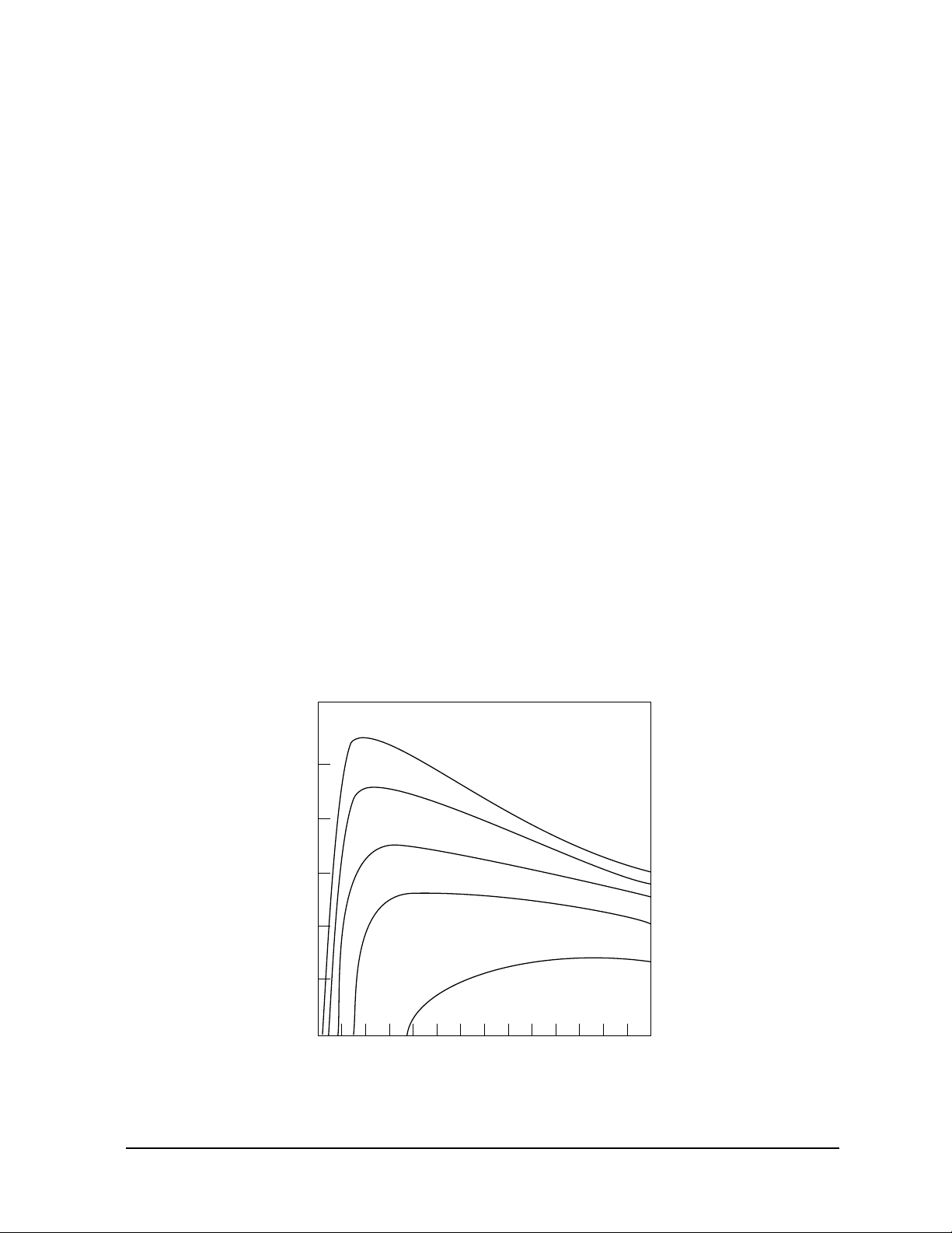
1.00. Figure 2-2 shows the radiant emittance values of a blackbody at various temperatures and wavelengths.
Most objects have emissivities that are less than 1.00 but are reasonably uniform at all
wavelengths of the infrared spectrum. These are called graybodies. The non-ideal
(less then 1.00) emissivity values of different materials can be compensated for, by the
emissivity controls, so that accurate temperature readings can be obtained. Emissivity
values for many common materials (both metals and non-metals) are listed in
Appendix B.
Figure 2-2: Blackbody Radiation Curves
2
10
2
1
10
1
-1
10
-2
10
-3
10
Blackbody Radiant Emittance (Watt/cm )
-4
10
12345678
0
Wavelength (Microns)
9 10111213
1500°C (2730°F)
1000°C (1830°F)
542°C (1000°F)
260°C (490°F)
20°C (70°F)
14
Page 16

2-4 Raynger 3i Series Operator’s Manual
2.3 YOUR PORTABLE INFRARED THERMOMETER
Portable infrared thermometers measure surface temperatures without touching the
surface. They collect the infrared energy radiated by a target and compute its surface
temperature. They also compute the running average, maximum, minimum, and differential temperatures and present them on a digital display in either degrees Celsius
or Fahrenheit. A digital/analog output allows data recording, instrumentation or
process control, and/or remote display of temperature and emissivity. The instru-6(. The instr)7.6contr is batmety powerared/ocan be powerared byionptatiitaAC adaprato7354.6(. he)]TJ0 -2.4158 Tg0 TwInmetiitamemoty cirart aum, anacs danalgnninfea-he
Page 17

Raynger 3i Series Operator’s Manual 2-5
Your portable thermometer has the following:
• Trigger—Two-stage trigger. The first stage activates the unit to take temperature
readings. The second stage is functional only in the datalog mode. To store a temperature reading, pull the trigger all the way in until you hear the tone (the tone
signals that the reading has been stored). When you release the trigger, the unit
goes to sleep.
• Control Panel and Display—All controls (except the trigger) are located on the
control panel. The display shows temperature and setup values, mode and loop
status, and operating information.
• Sighting System—Laser or scope sighting is provided with each model.
Note: Read the laser warning label before operating the laser.
• Analog Output—Connects the instrument to analog recording/printing devices
such as chart recorders and printers.
• Digital Output—An RS232 interface to connect the instrument to a computer or
directly to a printer’s RS232 port.
• DC In—AC adaptor connection.
Page 18

2-6 Raynger 3i Series Operator’s Manual
2.4 OPERATION AND CONTROLS
This section instructs you in the operation of the instrument. It describes battery
and/or AC adaptor installation and the controls and functions of the different control
loops and operating modes.
2.4.1 Battery/AC Adaptor Installation
The instrument may be powered by batteries or an AC adaptor. Battery power is supplied by 4 “AA” batteries. The batteries are located in the base of the handle. AC
power is supplied by an optional AC power adaptor (DIN VDE 0551 approved).
NiCad batteries can also be used, but battery life will be substantially reduced. Figure
2-3 shows the location of the battery compartment, battery orientation, and the location of the AC adaptor power connection.
Table 2-1 shows approximate battery life (for alkaline batteries) for various operating
conditions.
Notes: Battery types and brands vary in length of usable life. The values in Table 2-1 are
approximate for new alkaline batteries. The instrument will continue to read accurately up to 4 hours after the low battery icon displays if the laser and backlight are off.
Remove the batteries if the unit is not used for long periods of time.
220 VAC adaptors must have DIN VDE 0551 approval to be used with IEC Class 2
laser units.
Table 2-1: Battery Life (Alkaline)
CONDITION
Laser OFF Backlight OFF
Laser ON Backlight OFF
Laser OFF Backlight ON
Laser ON Backlight ON
"Sleep" mode (trigger off)
HOURS OF
CONTINUOUS USE
25
12.5
12.5
10
1 year
Page 19
Raynger 3i Series Operator’s Manual 2-7
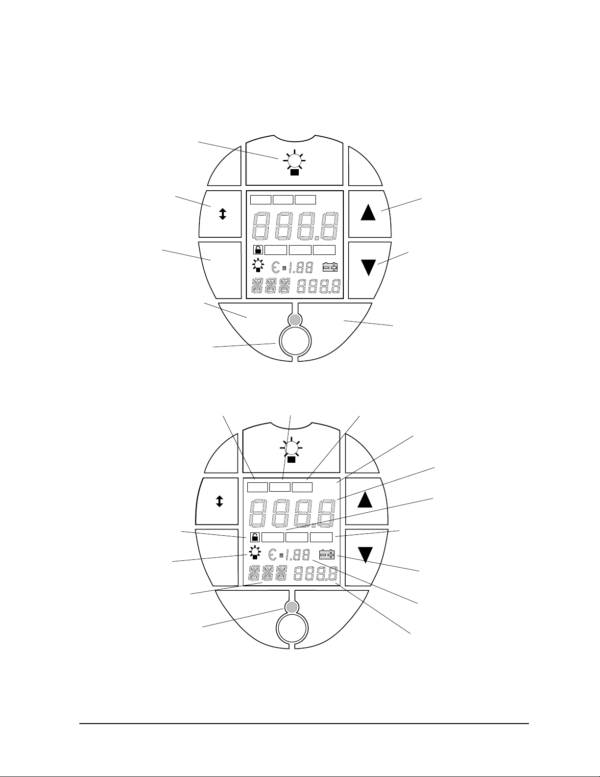
Figure 2-4: The Control Panel and Display
2.4.2 Control Panel and Display
Figure 2-4 shows the display and controls. Descriptions of these, in alphabetical
order, follow the illustration.
Backlight on/off
button
Run/Log
selector switch
Setup
button
Mode and Recall
button
Laser on/off button
Trigger lock
icon
Backlight
icon
RUN
RUN
LOG
LOG
SET
Data logger
icon
RUN
RUN
LOG
LOG
SET
LOG
HI
RECALL
MODE
•
•
MODE
RECALL
RCL
LOG
HI
RCL
SET
( )
LO
LASER
Recall
loop icon
SET
( )
( )
LO
°C °F
( )
T
amb
ACTIVATE
ACTIVATE
•
•
LOCK
LOCK
°C °F
T
amb
Increase/up
button
Decrease/down
button
Activate and trigger
lock button
Setup
loop icon
Celsius/Fahrenheit
icons
Temperature
display
High and low
alarm icons
Ambient temperature
compensation icon
Low battery icon
Mode display
Laser on/off LED
RECALL
MODE
•
•
MODE
RECALL
LASER
ACTIVATE
ACTIVATE
•
•
LOCK
LOCK
Emissivity display
Mode value display
Page 20

2-8 Raynger 3i Series Operator’s Manual
Activate button—Press the activate button to activate HAL, LAL, or TAM, or to toggle between DIG/ANA, or °C/°F, in the SET loop.
Backlight button and icon—The display has a backlight for working in low lighting
conditions. Press the backlight button to activate or deactivate the backlight. The
backlight icon is activated when the backlight is on. To save battery power, use the
backlight only when necessary. Note that if the battery voltage falls below 4.0 V, the
backlight will automatically turn off.
Low battery icon—The instrument is powered by four “AA” batteries. When the battery voltage falls below 4.6 V, the low battery icon is activated.
Note: Turning off the backlight and laser will extend the battery life (refer to Table 2-1 for
battery life under various conditions).
Celsius/Fahrenheit icons—The °C and °F icons indicate which temperature scale has
been selected.
LOG button and icon—Press the LOG/RUN button while you have the trigger
pulled to toggle between the LOG and RUN loops. The LOG icon is activated when
the instrument is in the LOG loop.
Emissivity display—The emissivity display shows the emissivity value selected in
either the RUN, RECALL, or LOG loops.
▲▲
and ▼▼buttons—▲ increases and ▼ decreases the emissivity settings, DOI rate,
HAL or LAL set-points, TAM, or the LOG location number.
High and Low alarm icons—These are activated when the corresponding alarms are
activated. The HAL icon flashes and the buzzer sounds when measured temperature
is greater than or equal to HAL and HAL is active. The LAL icon flashes and the
buzzer sounds when the measured temperature is less than or equal to LAL and LAL
is active. Note that when a high or low alarm condition is met and the unit is sending
out RS232 data while in the Digital Output mode, the buzzer will make two tones: a
normal tone followed by a higher pitched tone.
Laser on/off button and LED—Press the laser button to activate or deactivate the
laser (RUN and LOG loops only). The laser LED is activated when the laser is activated. (Not applicable for the scope sighting model.) Note that if the battery voltage
falls below 4.3 V, the laser will automatically turn off. Also, if the unit is in the LOCK
mode, the laser will go off when the trigger is released.
Temperature display—Shows the current temperature (while the trigger is pulled) or
the last temperature measured (when the RECALL button is pressed).
Page 21

Raynger 3i Series Operator’s Manual 2-9
Mode button—Press the mode button to change modes in any of the four loops.
Mode display and Mode value display—The Mode display shows the current mode
selected. The mode value display shows the temperature, set-point, or LOG location
value for the mode selected.
Recall button and icon—Press the RCL button to activate the RECALL loop. The
RECALL loop may be used to recall values from either the RUN or LOG loops. The
RCL icon is activated when the instrument is in the RECALL loop.
RUN button—Press the RUN/LOG button, when the trigger is pulled, to toggle
between the RUN and LOG loops.
Setup button and icon—Press the SET button to activate the SETUP loop. The
SETUP loop may be used to set values in either the RUN or LOG loops. The SET icon
is activated when the instrument is in the SET loop.
T
amb
icon—This is activated when the ambient temperature compensation function is
activated. This feature only affects readings in the RUN loop; readings in the LOG
loop are not affected.
Trigger lock icon—The small padlock is the trigger lock icon and is activated when
LOCK is pressed while the trigger is pulled. To unlock the trigger, simply press the
LOCK button again.
Page 22
2-10 Raynger 3i Series Operator’s Manual
2.4.3 Control System
The control system consists of four loops: SET, RUN, RECALL and LOG. The instrument may be cycled to any of the four loops by using the trigger or control panel buttons, as shown below.
RCL
LOG
SET
HI
( )
LASER
( )
LO
°C °F
T
amb
ACTIVATE
•
LOCK
RUN
LOG
SET
LOG
HI
MODE
•
RECALL
RCL
( )
LASER
SET
( )
LO
°C °F
T
amb
ACTIVATE
•
LOCK
RUN
LOG
SET
MODE
•
RECALL
RUN
LOG
SET
LOG
HI
MODE
•
RECALL
RCL
( )
LASER
SET
( )
LO
°C °F
T
amb
ACTIVATE
•
LOCK
Page 23

Raynger 3i Series Operator’s Manual 2-11
2.4.3.1 Control Loops
Each control loop has several modes, which are described in the following sections.
2.4.3.2 General Information
Before you begin using your portable instrument, you should be aware of the following general operating rules:
• The instrument goes to “sleep” (low power consumption, no display, no laser, no
backlight) after different times for each loop, as follows:
– SET Loop (after last button use): 10 seconds
– RUN Loop (after releasing the trigger): immediately
– RECALL Loop (after last button use): 10 seconds
_ LOG Loop (after releasing trigger): immediately
• The backlight can be turned on or off in any mode.
• The laser can be used only in the RUN and LOG loops.
• The trigger has two stages. The first stage is for measuring temperature. The second stage, when the trigger is pulled all the way in, is for storing temperature values in the LOG loop.
• The °C or °F icon flashes when the instrument is measuring temperature in the
RUN or LOG loops. It does not flash when values are recalled.
• You can lock the trigger in the RUN loop and the LOG loop.
• You must release the trigger to go into the SET or RECALL loops.
• When you simultaneously press the MODE and ACTIVATE buttons while in the
RUN loop, the instrument is reset to the RUN loop factory default settings (stored
data is unaffected). In the LOG loop, pressing the MODE and ACTIVATE buttons
not only resets the instrument to its LOG loop factory default settings, but also
clears all previously stored data. In both cases, the instrument will “beep” after
reinstalling the default settings. Section 3.6 lists default setting for each model as
well as non-model-specific default settings and range values.
IMPORTANT
For the short wavelength units (e.g., 2 µm and below)—Avoid taking
temperature measurements in bright sunlight. High levels of ambient
light may produce apparently valid high-temperature readings when
no target is in the thermometer’s field-of-view.
Page 24
2.4.4 RUN Loop–To Measure Temperature
The RUN loop is for taking temperature measurements. Figure 2-6 illustrates the
RUN loop.
To take a measurement, do the following:
1. Point the instrument at the target.
2. Pull the trigger (press the RUN/LOG button, if necessary, so that the LOG icon is
not activated).
Figure 2-6: RUN Loop
2-12 Raynger 3i Series Operator’s Manual
RUN
RUN
LOG
LOG
SET
RUN
RUN
LOG
LOG
SET
MAX Mode
RCL
LOG
( )
HI
RECALL
MODE
•
•
MODE
RECALL
LASER
LASER
MODE
RCL
LOG
( )
HI
SET
( )
LO
ACTIVATE
SET
( )
LO
°C °F
T
amb
ACTIVATE
•
•
LOCK
LOCK
°C °F
T
amb
Current
temperature
MODE
Turn the trigger
lock ( ) on or off
with the Lock button
The °C (or °F) icon
flashes when the
trigger is pulled
MODE
RUN
RUN
LOG
LOG
SET
RUN
RUN
LOG
LOG
SET
MIN Mode
RCL
LOG
( )
HI
RECALL
MODE
•
•
MODE
RECALL
LASER
MODE
RCL
LOG
( )
HI
LO
LASER
LO
SET
°C °F
( )
T
amb
ACTIVATE
ACTIVATE
LOCK
LOCK
SET
°C °F
( )
T
amb
•
•
Change emissivity
RECALL
MODE
•
•
MODE
RECALL
LASER
LASER
ACTIVATE
ACTIVATE
•
•
LOCK
LOCK
with the ▲ and ▼
buttons in any mode
RECALL
MODE
•
•
MODE
RECALL
LASER
LASER
ACTIVATE
ACTIVATE
•
•
LOCK
LOCK
DIF ModeAVG Mode
TRIGGER
Pulled or Locked
BUTTON
RUN
LOOP ICON
None
Page 25

Raynger 3i Series Operator’s Manual 2-13
3. Press the laser button to activate the laser (if equipped with laser sighting).
4. Carefully aim using the laser or scope.
Note: The laser or scope indicate the target (see Sections 2.7.1 through 2.7.4). Make sure the
spot you are measuring fills the target.
5. Read the temperature from the display.
RUN contains 4 modes: MAX, MIN, DIF, and AVG (as shown in Figure 2-7). In RUN,
the current temperature and emissivity setting along with either the MAX, MIN, DIF,
or AVG temperature can be displayed. Note that AVG is a weighted average of all
readings taken since the trigger was pulled. The unit uses the following formula to
calculate the running average (while the trigger is pulled):
R
1
+ R2+ R3+ ...R
n
= AVG
n
where R = a reading and n = the total number of readings.
• Press the MODE button to change modes.
• Press the ▲ or ▼ buttons to change emissivity.
• Press the backlight button if a brighter display is necessary.
Note: When you simultaneously press the MODE and ACTIVATE buttons while in the
RUN loop, the instrument is reset to its RUN loop factory default settings (stored data
is unaffected). The instrument will “beep” after reinstalling the default settings.
Section 3.6 lists default setting for each model as well as non-model-specific default settings and range values.
Page 26

2-14 Raynger 3i Series Operator’s Manual
2.4.5 LOG Loop–To Measure and Store Temperature
The LOG loop is for making temperature measurements and storing them in the data
logger locations. Figure 2-7 illustrates the LOG loop.
To use the modes and functions of the LOG loop, do the following:
1. Point the instrument at the target.
2. Pull the trigger and press the RUN/LOG button, if necessary, so that the LOG icon
is activated.
3. Press the ▲ or ▼ buttons to select the LOG location number where you want to
store the measurement. To change the emissivity setting for that location, press
the MODE button and use the ▲ or ▼ buttons .
4. Press the laser button to activate the laser (if equipped with laser sighting).
5. Carefully aim using the laser or scope.
6. Read the temperature from the display.
Figure 2-7: LOG Loop
LOC Mode MAX Mode
RCL
RUN
RUN
LOG
LOG
SET
LOG
SET
°C °F
( )
( )
HI
LO
T
amb
MODE
RUN
RUN
LOG
LOG
SET
LOG
RCL
SET
°C °F
( )
( )
HI
LO
T
amb
Lock and unlock
the trigger with
the lock button
RECALL
MODE
•
•
RECALL
MODE
ACTIVATE
ACTIVATE
•
•
LOCK
LOCK
LASER
LASER
TRIGGER
Pulled or locked
Use the ▲ and ▼
buttons to change
the log location (LOC)
number
BUTTON
LOG
RECALL
MODE
•
•
RECALL
MODE
LASER
LASER
LOOP ICON
LOG
ACTIVATE
ACTIVATE
•
•
LOCK
LOCK
Use the ▲ and ▼
buttons to change
the emissivity
Page 27

Raynger 3i Series Operator’s Manual 2-15
7. Pull the trigger further until you hear the “beep” indicating that the measurement
has been stored. Both the current and MAX temperatures are stored in memory.
Notes: The instrument has a 2-stage trigger. The first stage is activated by pulling the trigger
a small amount. The second stage (operational in LOG only) is activated when the
trigger is pulled all the way.
To protect the data from being accidentally overwritten (trigger accidently pulled),
press the RUN/LOG button to exit the LOG loop (the LOG icon is off).
8. Release the trigger.
LOG contains two modes: LOC (location) and MAX (as shown in Figure 2-7). In
LOG, the current temperature and emissivity setting along with either the location
number or MAX temperature can be displayed. Note the following:
• Press the MODE button to change between LOC and MAX modes.
• Press the ▲ or ▼ buttons to change the location number or the emissivity set-
ting.
• Press the backlight button if a brighter display is needed.
Notes: If you change the emissivity after storing data, both the target temperature and MAX
temperature will reset to zero. The instrument will “beep” to indicate this.
IMPORTANT
When you simultaneously press the MODE and ACTIVATE buttons
while in the LOG loop, all previously stored data is cleared. The
instrument also resets to its LOG loop factory default settings. The
instrument will “beep” after reinstalling the default settings. Section
3.6 lists default setting for each model as well as non-model-specific
default settings and range values.
Page 28

2-16 Raynger 3i Series Operator’s Manual
2.4.6 RECALL Loop–To Recall Measured Temperatures
The RECALL loop is for recalling values from either the RUN or LOG loops.
2.4.6.1 RECALL Values from RUN
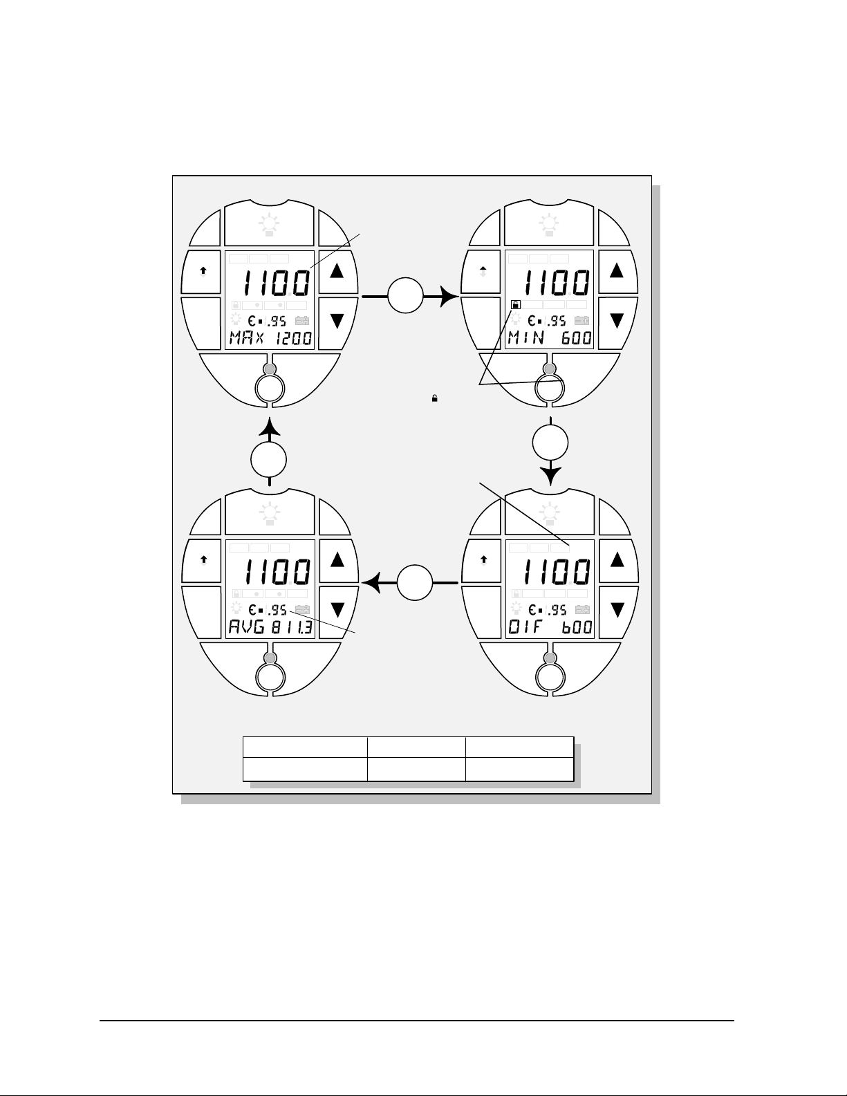
Figure 2-8 illustrates RECALL for RUN values.
RUN
LOG
SET
RUN
LOG
SET
LOG
RCL
( )
HI
LASER
MODE
SET
LO
LASER
ACTIVATE
LOCK
°C °F
( )
T
amb
ACTIVATE
•
LOCK
MODE
•
MODE
If the display goes out,
press the Recall button again
to continue the Recall function
RUN
LOG
SET
RUN
LOG
SET
LOG
LOG
HI
HI
RCL
( )
LO
LASER
MODE
RCL
( )
LO
LASER
SET
°C °F
( )
T
amb
ACTIVATE
LOCK
SET
°C °F
( )
T
amb
ACTIVATE
LOCK
•
•
Page 29

Raynger 3i Series Operator’s Manual 2-17
To recall values from the RUN loop, do the following:
1. Release or unlock the trigger, if necessary.
2. Press the RECALL button. The RCL icon will be activated.
3. Press the RUN/LOG button, if necessary, so that the LOG icon is not activated.
4. Read the recalled temperature from the display.
RECALL contains four modes: MAX, MIN, DIF, and AVG (as shown in Figure 2-8).
In RECALL, the last temperature and emissivity setting along with either the MAX,
MIN, DIF, or AVG temperature can be displayed. Note the following:
• Press the MODE button to change modes.
• Press the ▲ or ▼ button to change emissivity. (This shows the effect that a dif-
ferent setting would have. Note that if the target’s temperature is known, you
can determine its emissivity by this method. MAX, MIN, DIF, or AVG are not
updated.)
• Press the backlight button if a brighter display is needed.
2.4.6.2 RECALL Values from LOG
Figure 2-9 illustrates RECALL for LOG values.
Figure 2-9: RECALL Loop–Recalling LOG Values
LOC Mode MAX Mode
RCL
RUN
RUN
LOG
LOG
SET
RECALL
Press the Recall button
again, if display goes out,
to continue Recall function
LOG
MODE
RECALL
MODE
SET
°C °F
( )
( )
HI
LO
T
amb
ACTIVATE
LASER
LASER
ACTIVATE
•
•
LOCK
LOCK
Use the ▲ and ▼
buttons to change
the log location (LOC)
number
•
•
TRIGGER
Released & Unlocked
MODE
Stored temperature.
If no temperature
is stored, the display
shows all zeros.
BUTTON
RECALL & LOG
RUN
RUN
LOG
LOG
SET
Press the Mode
button to toggle
between the LOC
and MAX modes.
LOOP ICONS
RCL
LOG
( )
HI
RECALL
MODE
•
•
RECALL
MODE
LASER
LASER
LOG RCL
SET
( )
LO
°C °F
T
amb
ACTIVATE
ACTIVATE
•
•
LOCK
LOCK
Stored temperatures.
If no temperatures
are stored, the
displays show
all zeros.
Page 30

To recall values from the LOG loop, do the following:
1. Release or unlock the trigger, if necessary.
2. Press the RECALL button. The RCL icon will be activated.
3. Press the RUN/LOG button, if necessary, so that the LOG icon is activated.
4. Read the recalled temperature from the display.
5. Press the ▲ or ▼ buttons (LOC mode) to recall values from other LOG locations.
RECALL contains two modes: LOC (location) and MAX (as shown in Figure 2-9). In
RECALL, the stored temperature and emissivity setting along with either the location
number or MAX temperature can be displayed for each of the 100 LOG locations.
2-18 Raynger 3i Series Operator’s Manual
Page 31

Raynger 3i Series Operator’s Manual 2-19
2.4.7 SETUP Loop–To Setup and Activate Alarms and Features
The SETUP loop is for setting up and activating alarms and features in either the RUN
or LOG loops.
2.4.7.1 SETUP Values for RUN
Figure 2-10 illustrates SETUP for the RUN loop.
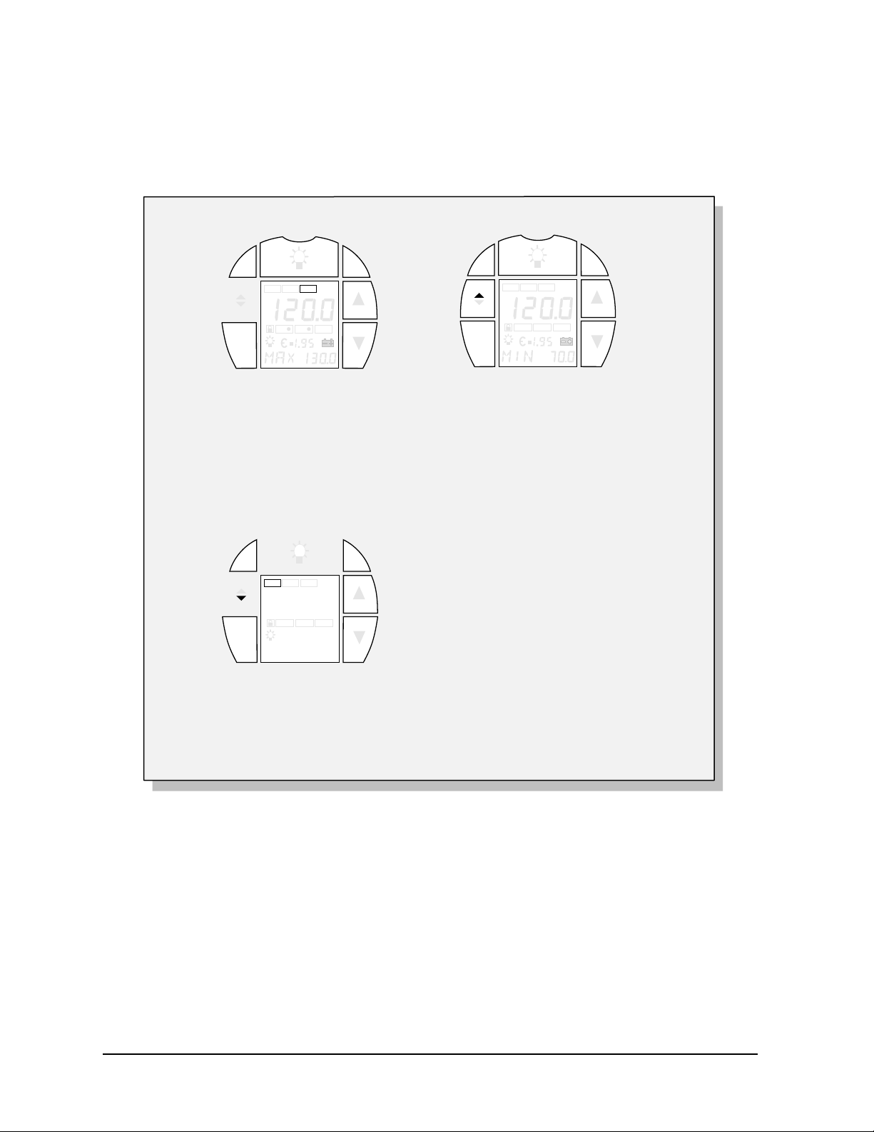
Figure 2-10: SETUP Loop–RUN Values
The display changes
to show temperature
in °C or °F
ANA
Selected
RUN
RUN
LOG
LOG
SET
F/C Mode
LOG
HI
RECALL
MODE
•
•
MODE
RECALL
RUN
RUN
LOG
LOG
SET
RCL
( )
LASER
LASER
MODE
SET
( )
LO
RECALL
°C °F
T
amb
ACTIVATE
ACTIVATE
•
LOCK
LOCK
MODE
LOG
HI
MODE
•
•
MODE
RECALL
•
DOI Mode
RCL
SET
( )
( )
LO
ACTIVATE
LASER
LASER
DIG
Selected
MODE
Press the ACTIVATE
button to toggle
between °C or °F
°C °F
T
amb
ACTIVATE
•
•
LOCK
LOCK
Turn the High
Alarm (HAL) on
or off with the
ACTIVATE Button
Time (in seconds)
between data
transmissions
Press ▲ or ▼ to
change the interval
(from 1 to 9999 seconds)
RUN
RUN
LOG
LOG
SET
RUN
RUN
LOG
LOG
SET
HAL Mode
RCL
LOG
( )
HI
RECALL
MODE
•
•
MODE
RECALL
LASER
LASER
MODE
RCL
LOG
( )
HI
RECALL
MODE
•
•
MODE
RECALL
LASER
LASER
MODE
SET
( )
T
LO
ACTIVATE
ACTIVATE
LOCK
LAL Mode
SET
( )
LO
T
ACTIVATE
ACTIVATE
LOCK
°C °F
amb
•
LOCK
°C °F
amb
•
LOCK
•
•
Change the High
Alarm setpoint with
the ▲ and ▼ buttons
Turn the Low
Alarm (LAL) on
or off with the
ACTIVATE
Button
Change the Low
Alarm setpoint with
the ▲ and ▼ buttons
Last temperature
value changes if
is activated
T
amb
RCL
LOG
SET
( )
HI
LO
RECALL
MODE
•
•
MODE
RECALL
LASER
LASER
TAM Mode
LOOP ICON
SET
°C °F
( )
T
amb
ACTIVATE
ACTIVATE
LOCK
LOCK
•
•
Change the TAM
setpoint with the
▲ and ▼ buttons
Turn the Ambient
Temperature (T
on or off with the
ACTIVATE Button
amb
)
Press the ACTIVATE
button to toggle
between DIG or ANA
RCL
LOG
RUN
RUN
LOG
LOG
( )
HI
LO
SET
RECALL
MODE
•
•
MODE
RECALL
LASER
LASER
DIG/ANA Mode
Released & Unlocked
SET
°C °F
( )
T
amb
ACTIVATE
ACTIVATE
•
•
LOCK
LOCK
TRIGGER
MODE
BUTTON
SET & RUN
RUN
RUN
LOG
LOG
SET
Page 32

To setup values for the RUN modes and functions, do the following:
1. Release or unlock the trigger, if necessary.
2. Press the SET button. The SET icon will be activated.
3. Press the RUN/LOG button, if necessary, so that the LOG icon is not activated.
4. Press ACTIVATE to toggle between °C or °F for the display and data output.
5. Press the MODE button to switch between HAL, LAL, TAM, and DOI. Press the
▲ or ▼ buttons to change the HAL, LAL, TAM, and DOI settings.
6. Press ACTIVATE to activate the HAL, LAL, or TAM.
7. Press ACTIVATE to toggle between DIG (digital) or ANA (analog) outputs.
8. Press the ▲ or ▼ buttons to set DOI (Digital Output Interval) if DIG was selected.
SET contains six modes: °C/°F, HAL, LAL, TAM, DIG/ANA, and DOI (as shown in
Figure 2-10). In SET, the temperature scale can be set for °C or °F, the HAL, LAL, and
TAM setpoints can be displayed and set, the digital (DIG) or analog (ANA) output
can be selected, and the Digital Output Interval (DOI) can be set. Note the following:
• Press the MODE button to change modes.
• Press the backlight button if a brighter display is needed.
Notes on setting T
amb
(Ambient temperature compensation)—The T
amb
icon is
activated when the ambient temperature compensation function is active. Targets
that have low emissivities will reflect energy from nearby objects. This additional
reflected energy is added to the target’s own emitted energy and may result in inaccurate readings. In some situations objects near the target (machines, furnaces, or other
heat sources) have a temperature much higher than that of the target. In these situations it is necessary to compensate for the reflected energy from those objects. Note
that the T
amb
feature is disabled if the emissivity is set to 1.00.
To set or change the ambient temperature compensation, complete the following:
1. Go to the RUN loop (pull trigger, press RUN/LOG button, if necessary).
2. Set the emissivity value to 1.0.
3. Press the MODE button until the mode function indicator displays AVG (average
temperature).
4. Pull the trigger and scan across objects and surfaces that face the target. Read the
average temperature value in the MODE value display. This is the value to be
entered as the reflected ambient temperature in Step 7 below. Release the trigger.
5. Press the SET button (do not pull the trigger) to enter the Setup mode
6. Press the MODE button until TAM shows in the mode function indicator.
2-20 Raynger 3i Series Operator’s Manual
Page 33

Raynger 3i Series Operator’s Manual 2-21
7. Set the TAM value by pressing the ▲ and ▼ buttons.
8. Press the ACTIVATE button to turn on the ambient temperature compensation
function. The Tamb icon will be displayed indicating that it is active. (Pressing
ACTIVATE again turns off the function.)
9. Pull trigger and reset the emissivity to the proper value for the target. You can
now take the target’s temperature using normal procedures. The current temperature and all computed values, as well as the analog and digital outputs, will now
be based on the compensated measurement.
Note: TAM only affects readings in the RUN loop; LOG loop readings are not affected.
2.4.7.2 SETUP Values for LOG
Figure 2-11 illustrates SETUP for the LOG loop.
To setup values for the LOG modes and functions, do the following:
1. Release or unlock the trigger, if necessary.
2. Press the SET button. The SET icon will be activated.
3. Press the RUN/LOG button, if necessary, so that the LOG icon is activated.
4. Press the ▲ or ▼ buttons to select the LOG location number (LOC mode).
Figure 2-11: SETUP Loop–LOG Values
LOC Mode HAL Mode
RUN
RUN
LOG
LOG
SET
Press the Set button
again, if the display
goes out, to continue
the SETUP functions
LOG
RECALL
MODE
RECALL
MODE
SET
°C °F
( )
( )
HI
LO
T
amb
ACTIVATE
LASER
LASER
ACTIVATE
•
•
LOCK
LOCK
•
•
TRIGGER
Released & Unlocked
MODE
Press the ▲ and ▼
buttons to change the
Log Location (LOC)
number.
You can select and
log data in any location
number from 1 to 100.
BUTTON
SET & LOG
RUN
RUN
LOG
LOG
SET
Turn High Alarm
on or off with the
Activate button
RCL
LOG
( )
HI
RECALL
MODE
•
•
RECALL
MODE
LASER
LASER
LOOP ICON
LOG SET
SET
( )
LO
ACTIVATE
ACTIVATE
RCL
°C °F
T
amb
•
•
LOCK
LOCK
Change the High Alarm
temperature value with
the ▲ and ▼ buttons
Page 34

5. Press the MODE button.
6. Press the ▲ or ▼ buttons to change the HAL setting (HAL mode).
7. Press ACTIVATE to activate the HAL setting for the selected location.
SET contains two modes: LOC and HAL (as shown in Figure 2-11). In SET, the LOG
location can be selected and the high alarm value (HAL) can be set for each location
(independent of the setting for the RUN loop). Note the following:
• Press the MODE button to change modes.
• Press the backlight button if a brighter display is needed.
2.5 USING A TRIPOD
The instrument is equipped with a standard camera-type tripod mount fitting at the
base of the handle. You can set it up for continuous use by mounting it on a sturdy
tripod. This allows the instrument to be connected to a digital or analog recording or
controlling device (computer, printer, chart recorder, line or temperature controller) to
monitor temperatures over long periods of time.
Mounting the instrument is easy. Just attach it to the tripod by screwing the tripod’s
mounting screw into the fitting at the bottom of the handle.
You can also connect a digital or analog recording or controlling device to the digital/analog connector (labeled OUT) on the side of the instrument. For continuous
monitoring, pull the trigger and press the LOCK button.
Note that battery life is shortened by continuous use. If you plan to monitor temperatures over long intervals, you should connect an AC adaptor to the DC IN connector.
2-22 Raynger 3i Series Operator’s Manual
Page 35

Raynger 3i Series Operator’s Manual 2-23
2.6 DATA OUTPUTS
Data outputs from the instrument provide a direct interface to chart recorders, printers, and computers. All models are equipped with an output jack capable of providing analog and digital signals, which are user selectable in the SET loop. The format
of these signals are as follows:
• Digital: RS-232
Format: ASCII data
Baud Rate: 9600
Data Format: 8 bits, 1 stop bit, no parity
• Analog: 1 mV/° (°C or °F) for all models except the 1M
1 mV/°C or 0.5 mV/°F for the 1M
Figure 2-12: Data Outputs
F0072 E095 MAX 0080
F0072 E095 MAX 0080
F0072 E095 MAX 0080
F0072 E095 MAX 0080
F0072 E095 MAX 0080
F0072 E095 MAX 0080
F
0
0
7
2
E
0
F
9
0
5
0
7
M
2
A
X
E
0
0
F
9
0
0
5
8
0
0
7
M
2
A
X
E
0
0
9
0
5
8
F
0
0
M
0
A
7
X
2
0
E
0
0
8
9
F
0
5
0
0
M
7
A
2
X
E
0
0
0
9
8
F
5
0
0
0
M
7
A
2
X
E
0
0
0
F
9
8
0
5
0
0
7
M
2
A
X
E
0
0
9
0
F
5
8
0
0
0
M
7
A
2
X
E
0
0
0
F
9
8
0
5
0
0
7
M
2
A
X
E
0
0
9
0
5
8
0
M
A
X
0
0
8
0
RS232
RS232
Analog
Page 36

2.6.1 Digital Output
The following sections describe the digital data outputs for each mode.
2.6.1.1 Data Output—RUN Loop
In the RUN loop, the temperature scale, current temperature, emissivity, mode temperature (MAX, MIN, DIF, or AVG), HAL or LAL, a carriage return, and a line feed
are sent out at intervals determined by the DOI (set in the SET loop) when the trigger
is pulled. HAL or LAL is sent out if the temperature is above HAL or below LAL
(when they are activated). Three blank spaces replace HAL or LAL if they do not
meet this condition. There are 5 characters for the mode temperature. The fifth character is always a space for MAX, MIN, or DIF. For AVG, the fifth character is a space
if the average temperature is 1000° or above. Average temperatures up to 999.9° use
all 5 characters. A total of 29 characters are sent out.
Table 2-2 shows a sample output. The headings at the top of the table explain the contents of each column (these are not part of the output).
2-24 Raynger 3i Series Operator’s Manual
Table 2-2: RUN Mode Output Example
S
p
a
°C
c
e
or °F Temp Emissivity Value Mode Temperature 3 Blank Spaces Return Feed
S
p
a
Main E for Emissivity Mode HAL, LAL, or
c
e
S
p
a
c
e
S
p
a
c
e
S
p
a
c
e
S
p
a
c
e
Carriage Line
F 0072 E 0 . 95 MAX 0072 <CR> <LF>
F 0073 E 0 . 95 MAX 0073 <CR> <LF>
F 0090 E 0 . 95 MAX 0090 <CR> <LF>
F 0070 E 0 . 95 MAX 0090 <CR> <LF>
F 0071 E 0 . 95 MAX 0090 HAL <CR> <LF>
F 0081 E 0 . 95 MAX 0090 <CR> <LF>
F 0080 E 0 . 95 MAX 0090 <CR> <LF>
F 0070 E 0 . 95 MIN
F 0070 E 0 . 95 DIF
F 0081 E 0 . 95 AVG
F –018 E 0 . 95 AVG
F 0421 E 0 . 95 AVG
F 1480 E 0 . 95 AVG
0070 <CR> <LF>
0020 <CR> <LF>
088.4 <CR> <LF>
–11.5 <CR> <LF>
100.0 <CR> <LF>
999.9 <CR> <LF>
F 1900 E 0 . 95 AVG 1000 <CR> <LF>
F 0071 E 0 . 95 MAX 0090 <CR> <LF>
F 0081 E 0 . 95 MIN
F 0081 E 0 . 95 MIN
C
0027 E 0 . 95 MIN –028 <CR> <LF>
C
0027 E 1 . 00 MIN –028 <CR> <LF>
–018 LAL <CR> <LF>
–018 <CR> <LF>
Notes
(see below)
1
2
3
4
5
6
7
8
9
10
11
Page 37

Raynger 3i Series Operator’s Manual 2-25
Notes:
1. Indicates HAL is active and temperature HAL value.
2. Mode changed to MIN.
3. Mode changed to DIF.
4. Mode changed to AVG.
5. Main and Average temperatures went negative.
6. Average temperature goes positive and is 100°F.
7. Average temperature is up to 999.9°F.
8. Average temperature is now greater than 999.9°F so decimal point is no longer
displayed.
9. Indicates LAL is active and temperature LAL value.
10. Scale is changed from °F to °C.
11. Emissivity is changed to 1.00.
2.6.1.2 Data Output—SET Loop
After entering the SET loop (SET icon activated), setup parameters can be sent out by
pressing the SET button again. This information can be sent out at any time while still
in the SET loop. Unactivated setpoints are printed in lowercase (e.g., hal) and activated setpoints are printed in uppercase (e.g., HAL). Hi Alarm, Low Alarm, T. Ambient,
Temperature Scale, and DOI are sent out and terminated by a carriage return and line
feed. A total of 39 characters are sent out. The SET values will be printed any time
you press the SET button. Two examples follow:
hal 0085 lal 0065 tam 0100 F;DOI 3600<CR><LF>
(hal, lal, tam not activated)
HAL 0085 lal 0065 tam 0100 F;DOI 3600<CR><LF> (HAL activated)
The above lines indicate Hi Alarm = 85, Low Alarm = 65, T. Ambient = 100, the temperature scale is °F, and DOI = 3600 seconds. (The <CR> and <LF> do not print; these
denote the carriage return and line feed.)
Note: DOI does not apply to the SETUP mode.
Page 38

2.6.1.3 Data Output—LOG Run Loop
When you press the trigger (first stage only) in the LOG Loop, data will be sent out
only for those locations that have stored data. The temperature scale, stored main
temperature, stored emissivity, stored MAX temperature, location number, HAL, a
carriage return, and a line feed are sent out when the trigger is pressed. HAL is sent
out if the stored temperature is above or equal to the HAL value for that location, and
HAL is activated. Three spaces replace HAL if this condition is not satisfied. A total
of 32 characters are sent out.
Table 2-3 shows a sample output. The headings at the top of the table explain the contents of each column (these are not part of the output).
Notes:
1. Current and MAX temperature stored at Location 1.
2. Current and MAX temperature stored, and the emissivity changed to 1.00 at
Location 6.
3. Current and MAX temperature stored at Location 7, HAL is active, and the
stored temperature is HAL value. When the 2-stage trigger is pulled all the
way to store the current and maximum temperatures at Location 7, the current
temperature also exceeded the HAL value, which was activated. Therefore,
HAL was sent out at the end of the string.
Notes: Note that in the above example nothing was stored at locations 2, 3, 4, 5, and 8 through
99, so these locations were not sent out. There will be a pause in printing between
locations 1 and 6 and between locations 7 and 100 because the unit is searching
through the locations sequentially for stored data.
DOI does not apply to the LOG mode.
2-26 Raynger 3i Series Operator’s Manual
Table 2-3: LOG Run Mode Output Example
S
p
a
°C
c
e
or °F Temp Emissivity Value Mode Temperature Number HAL Return Feed
S
p
a
Main E for Emissivity Stored MAXMAX Location
c
e
S
p
a
c
e
S
p
a
c
e
S
p
a
c
e
S
p
a
c
e
F 0072 E 0 . 95 MAX 0090 001 <CR> <LF>
F 0095 E 1 . 00 MAX 0100 006 <CR> <LF>
F 0070 E 0 . 95 MAX
F 0090 E 0 . 97 MAX
0090 007 HAL <CR> <LF>
0100 100 <CR> <LF>
S
p
a
c
e
Carriage Line
Notes
(see below)
1
2
3
Page 39

2.6.1.4 Data Output—LOG SETUP Loop
After entering the LOG SETUP loop (both the LOG and SET icons are activated),
setup parameters are sent out when the SET button is pressed again. This information can be sent out at any time in the LOG SETUP mode. HAL, temperature scale,
and the location number are sent out and terminated by a carriage return and line
feed. A total of 16 characters are sent out. Go to the appropriate location number in
the LOG loop and press the SET button to send out the Hi Alarm value for that location. Activated Hi Alarm locations are uppercase (HAL), and unactivated Hi Alarm
locations are lowercase (hal). Only the HAL value at the present location is sent out.
For additional HAL values, go to the appropriate location and press SET again while
still in any of the two screens in the LOG SETUP mode. To get the LOG SETUP para-
meters for all 100 log locations, press the SET button for about 3 seconds.
Table 2-4 shows a sample output. The headings at the top of the table explain the contents of each column (these are not part of the output).
Notes:
1. For Location 1, HAL is not activated and is 1000°F.
2. For Location 2, HAL is activated and is 1000°F.
3. For Locations 3, 4, 5, 6, and 7, HAL is not activated and is 85°F.
4. For Location 8, HAL is activated and is 65°F.
Note: DOI does not apply to the LOG SETUP mode.
Raynger 3i Series Operator’s Manual 2-27
Table 2-4: LOG SETUP Mode Output Example
S
S
p
a
hal
c
e
or HAL Value or °F Number Return Feed
S
p
p
a
a
HAL °C Location
c
c
e
e
Carriage Line
Notes
(see below)
hal 1000 F 001 <CR> <LF>
HAL 1000 F 002 <CR> <LF>
hal 0085 F 003 <CR> <LF>
hal 0085 F 004 <CR> <LF>
hal 0085 F 005 <CR> <LF>
hal 0085 F 006 <CR> <LF>
hal 0085 F 007 <CR> <LF>
HAL 0065 F 008 <CR> <LF>
1
2
3
3
3
3
3
4
Page 40

2.6.2 Analog Output
The analog output is made up of the following:
• Output: 1 mV/° (°C or °F) for all models except 1M
1 mV/°C or 0.5 mV/°F for the 1M
• Output impedance: 1.3 K
W
Use the signal output jack accessory.
The analog output represents the current temperature of the object being measured,
regardless of the mode used. If T
amb
compensation is activated, the analog output
will be representative of the compensated temperature values.
2-28 Raynger 3i Series Operator’s Manual
Page 41

Raynger 3i Series Operator’s Manual 2-29
2.7 SIGHTING SYSTEMS
The aiming options for this instrument are laser(s), scope, or laser and scope combination. Laser sighting is available in single or dual spot models or in a crossed laser model.
Two different laser power levels are available for this product. Please refer to the label on
your unit and to the following label diagrams (Figure 2-13) to determine the one that you
have. The following table shows the specifications for both laser types.
CAUTION
Use of controls or adjustments, or performance of procedures other than
those specified herein, may result in hazardous laser radiation exposure.
WARNING—LASER SAFETY
Models with laser sighting produce visible laser radiation that may be
harmful to the human eye. Be aware of the following:
• Avoid direct exposure of human eyes to laser light. Eye damage can
result.
• Use extreme caution when operating.
• Never point the unit at another person.
• Keep out of the reach of children.
• Refer to the FDA laser label on the unit for specific information.
To operate the laser, do the following:
1. Point the instrument toward the spot being measured. (Do not point it at anyone.)
2. Pull the trigger.
3. Press the Laser button on the control panel.
4. Aim accordingly. (Refer to the following sections for laser aiming information.)
Note: The laser turns off automatically when the trigger is released. It cannot be locked on when
the trigger is locked. It cannot be turned on in the Recall and Setup loops.
Table 2-5: Laser Specifications
FDA Class IIIa FDA Class II and IEC Class 2
Type
Wavelength
Power
Operating Range
(depending on ambient
light level)
Gallium Arsenide
630-670 nm
<5 milliwatt
Up to 30 m (100 ft)
Gallium Arsenide
630-670 nm
<1 milliwatt
Up to 15 m (50 ft)
Page 42

2-30 Raynger 3i Series Operator’s Manual
FDA Class II
Figure 2-13: Laser Labels
AVOID EXPOSURE LASER RADIATION IS
EMITTED FROM THIS
APERTURE.
CAUTION
LASER RADIATION - DO
NOT STARE INTO BEAM
OUTPUT < 1mW
WAVELENGTH 630-670 nm
CLASS II LASER PRODUCT
COMPLIES WITH
FDA 21 CFR
SUBCHAPTER J
FDA Class IIIa
IEC Class 2
POR ESTA ABERTURA
SE EMITE RADIACION
LASER. EVITE
EXPONER LA VISTA.
AVOID EXPOSURE LASER RADIATION IS
EMITTED FROM THIS
APERATURE.
<1mW/630–670nm
IEC 825/93
PELIGRO
RADIACION LASER – EVITE
EXPONER LA VISTA
SALIDA < 5mW
`
LONGITUD DE ONDA 630-670 nm
PRODUCTO LASER CLASE IIIa
DANGER
LASER RADIATION - AVOID
DIRECT EYE EXPOSURE
OUTPUT < 5mW
WAVELENGTH 630-670 nm
CLASS IIIa LASER PRODUCT
LASER LIGHT
DO NOT STARE INTO BEAM
CLASS 2 LASER
RAYONNEMENT LASER
NE PAS EXPOSER L'OEIL
AU RAYON LASER
LASER DE CLASSE 2
CUMPLE CON LAS
NORMAS FDA 21 CFR
SUB CAPITULO J
COMPLIES WITH
FDA 21 CFR
SUBCHAPTER J
LASERLIGHT
NICHT IN DEN STRAHL
BLICKEN
LASER KLASSE 2
RAYO LASER
NO FIJAR LA VISTA
EN EL RAYO
LASER CLASE 2
Page 43

Raynger 3i Series Operator’s Manual 2-31
2.7.1 Single Laser Sighting
A single laser unit (see Figure 2-14) indicates the center of the area being measured,
not the diameter of the spot. (To find out the diameter of the spot being measured,
refer to the optical charts in Appendix A.)
2.7.2 Dual Laser Sighting
A dual laser unit indicates the diameter of the spot being measured. To take a measurement, aim the unit at the target and move closer or farther until the target is within the laser dots.
Note: The IR and laser spot diameters are not the same at close distances. The distance
between the laser beams is slightly greater than the spot being measured. Refer to
Figure 2-15 for a comparison of the IR spot and laser beam diameters.
Figure 2-15: Dual Laser and IR Spot Diameters
Figure 2-14: Single Laser Sighting
Dual Laser Focus Point D:S = 75:1 @ 15 m (50 ft) Far Field D:S = 68:1
DISTANCE: SENSOR TO OBJECT (ft)
0
SPOT DIA. (in)
SPOT DIA. (mm)
02
IR Spot Diameter at Lens = 23 mm (0.9 in)
Laser Diameter at Lens = 40 mm (1.6 in)
10 20 30 40 50
16
12
8
4
0
75
150
225
300
4 6 8 10 12 14 16
DISTANCE: SENSOR TO OBJECT (m)
IR
LASER
Page 44

2-32 Raynger 3i Series Operator’s Manual
2.7.3 Crossed Laser Sighting
The distance at which the two laser dots overlap is the point where the smallest area
is measured (Focus Point). To find this distance, aim the unit at the target and move
closer or farther until the laser beams overlap. Refer to Figure 2-16 for a comparison
of the IR spot and laser beam diameters.
2.7.4 Scope Sighting
Scope sighting models (Figure 2-17) have parallax-free sighting (at the focus distance).
Look through the scope. There are one or two circular reticles, depending on model.
The inner reticle indicates the area that is measured at the focus point (see Appendix
A for the focus point distance for your model). The outer reticle indicates an area
greater than or equal to the area that is measured at all other distances.
Figure 2-16: Crossed Laser and IR Spot Diameters
Figure 2-17: Scope Sighting
Crossed Laser Focus Point D:S = 75:1 Far Field D:S = 20:1
DISTANCE: SENSOR TO OBJECT (in)
0
24 36 60 120 180
12
Focus Point
0.3 in @ 24 in
SPOT DIA. (in)
Focus Point
8 mm @ 610 mm
SPOT DIA. (mm)
0 610
1000 1500 3000 5000
DISTANCE: SENSOR TO OBJECT (mm)
9
6
3
0
75
150
225
300
Page 45

Raynger 3i Series Operator’s Manual 2-33
2.7.5 Scope with Laser Sighting
The scope and single laser sighting model (Figure 2-18) combines the parallax-free sighting of the scope with the convenience of the laser. The combination unit has a single
class 2 laser. It indicates the center of the target being measured, not the diameter of the
spot being measured. See section 2.7.1 and Figure 2-14 for further details on the laser.
The scope has one reticle and it indicates the target area that is measured at the focus
point (see Appendix A for the focus point distance of your model). See section 2.7.4 and
Figure 2-17 for further details on the scope.
Figure 2-18: Scope with Laser Sighting
Page 46

2-34 Raynger 3i Series Operator’s Manual
Page 47

Raynger 3i Series Operator’s Manual 3-1
3.0 SPECIFICATIONS
This section covers the following specifications:
• Thermal
• Operational
• Electrical
• Environmental
• Physical
Also covered are factory default settings for each model as well as factory default settings and range values for all models.
3.1 THERMAL
Table 3-1 lists thermal specifications for each model.
Table 3-1: Thermal Specifications
* The instrument may measure temperature a few degrees below the minimum and
above the maximum specified temperature range.
Note: Hi Alarm, Lo Alarm, and T. Ambient ranges are the same as measurement ranges in
Table 3-1.
1M 2M G5 P7
600 to 3000°C
1.0 micron
Silicon diode
±0.5% of reading or ±1°C (±1°F), whichever is greater
200 to 1800°C
(400 to 3275°F)
1.6 micron
InGaAs diode
±3mV of display reading
150 to 1800°C
(300 to 3275°F)
5 micron
Thermopile
10 to 800°C
(50 to 1450°F)
7.9 micron
Thermopile
Measurement
Range
Spectral
Response
Detecting
Element
Display
Accuracy
Analog Output
Accuracy
Repeatability
Temperature
Coefficient
LT, LR, LRSCL2
-30 to 1200°C
(-20 to 2200°F)
8 to 14 micron
Thermopile
±1% of reading (±0.5% for 1M) or ±1°C (±1.5°F), whichever is greater, or ±2°C (±4°F)
for targets below 0°C (32°F), at 23°C ±5°C (73°F ±9°F) ambient operating temp.
(1100 to 5400°F)
±0.1°C (±0.1°F) change per 1°C (1°F) change in ambient temperature
Page 48

3-2 Raynger 3i Series Operator’s Manual
3.2 OPERATIONAL
Table 3-2 lists operational specifications for each model.
Table 3-2: Operational Specifications
Temperature
Display
Display and Digital
Output Resolution
Display Controls
Emissivity
DOI (Digital
Output Interval)
Analog Output
Resolution
LOG Locations
Response Time
(95% response)
LT, LR, LRSCL2
°C or °F (selectable), multifunctional 4-digit backlit LCD
1°C or 1°F (0.1°C or 0.1°F in AVG Mode for temperatures up to 999.9°)
Adjustable from 0.10 to 1.00 in 0.01 increments (default = 0.95)
700 msec 550 msec 700 msec 700 msec550 msec
1M 2M G5 P7
Membrane Switch Panel
1 to 9999 seconds
1°C or 1°F
1 to 100
Page 49

Raynger 3i Series Operator’s Manual 3-3
Table 3-3: Electrical Specifications
3.3 ELECTRICAL
Table 3-3 lists electrical specifications for each model.
LT, LR, LRSCL2 1M 2M G5 P7
Analog Output
Analog Output
Range
Analog Output
Impedance
Digital Output
Digital Output
Range
Power
Requirements
1mV/°C (1mV/°F) 1mV/°C (1mV/°F)
Four (4) AA alkaline or rechargeable batteries or 6 to 9 volt, 200 mA, DC power supply
1mV/°C (0.5mV/°F)
Same as Measurement Range in Table 3-1
1.3 KΩ
RS232, 9600 baud
Same as Measurement Range in Table 3-1
Page 50

3-4 Raynger 3i Series Operator’s Manual
3.4 ENVIRONMENTAL
Table 3-4 lists environmental specifications for each model.
Table 3-4: Environmental Specifications
3.5 PHYSICAL
Table 3-5 lists environmental specifications for each model.
Table 3-5: Physical Specifications
Note: The laser will turn off automatically if the instrument’s internal temperature exceeds
45° C (113° F).
LT, LR, LRSCL2
Relative
Humidity
Storage
Temperature
Ambient
Operating
Temperature
1M
10 to 95% at up to 30°C (86°F)
under non-condensing conditions
-20 to 50°C (-4 to 120°F)
0 to 50°C (32 to 120°F)
2M G5 P7
without battery
SCOPE & LASER
244 mm (9.6 in) H
257 mm (10.1 in) L
71 mm (2.8 in) W
1000 g (2.21 lbs)
Dimensions
Weight
SCOPE MODELSLASER MODELS
208 mm (8.2 in) H
257 mm (10.1 in) L
71 mm (2.8 in) W
794 g (1.75 lbs) 1000 g (2.21 lbs)
244 mm (9.6 in) H
257 mm (10.1 in) L
71 mm (2.8 in) W
Page 51

Raynger 3i Series Operator’s Manual 3-5
3.6 DEFAULT VALUES
Table 3-6 lists the factory default values for each model.
Table 3-6: Model Specific Factory Default Values
Table 3-7 lists factory default settings that are valid for all models.
Table 3-7: Non-Model Specific Factory Default Values
Hi Alarm Lo Alarm T. Ambient
LTDL, LTCL, LTSC,
LRSC, LRL, LRSCL2
1200°C
(2200°F)
0°C
(0°F)
23°C
(73°F)
1MSC, 1ML
P7DL
G5SC
2MSC, 2ML
3000°C
(5400°F)
800°C
(1450°F)
1800°C
(3275°F)
1800°C
(3275°F)
600°C
(1100°F)
10°C
(50°F)
150°C
(300°F)
200°C
(400°F)
600°C
(1100°F)
23°C
(73°F)
150°C
(300°F)
200°C
(400°F)
Function Default
Emissivity
DOI (Digital Output Interval)
Digital/Analog Output
Trigger LOCK
Laser
Backlight
HAL
LAL
TAM
Scale: U.S.
Scale: Outside U.S.
Loop
Setup Screen (RUN Loop)
Setup Screen (LOG Loop)
LOG Location
0.95
60 seconds
Analog Output
off
off
off
off
off
off
degrees F
degrees C
RUN Loop, MAX Mode
F/C
LOC (Location)
1
LOG Data–All Locations
Current Temperature
MAX Temperature
Hi Alarm Value
Hi Alarm State
Emissivity
0 degrees C, or 0 degrees F
0 degrees C, or 0 degrees F
See Table 3-6
off
0.95
Page 52

3-6 Raynger 3i Series Operator’s Manual
Note: When you simultaneously press the MODE and ACTIVATE buttons while in the
RUN loop, the instrument is reset to its RUN loop factory default settings (stored data
is unaffected). In the LOG loop, pressing the MODE and ACTIVATE buttons not only
resets the instrument to its LOG loop factory default settings, but also clears all previously stored data. In both cases, the instrument will “beep” after reinstalling the
default settings. Section 3.6 lists default setting for each model as well as non-modelspecific default settings and range values.
3.7 REGULATORY
The appropriate regulatory approvals and certificates have been issued as follows:
• FDA Class II Laser Certification
• FDA Class IIIa Laser Certification
• IEC Class 2 Laser Certification
• IEC801-3 (EN50082) for EMI susceptibility
Page 53

Raynger 3i Series Operator’s Manual 4-1
4.0 MAINTENANCE
4.1 BATTERY REPLACEMENT
When the battery icon comes on, you need to replace the batteries. To open the
battery compartment, press gently on the middle of the sliding panel (located on the
bottom of the handle) and slide it to the rear of the unit. Remove the batteries and
replace with four AA batteries. Be sure to insert the new batteries so they point in the
proper direction. (A symbol on the side of the handle shows the proper battery orientation.) Replace the battery compartment cover.
4.2 CLEANING
You should periodically clean the instrument’s front window and housing.
4.2.1 Front Window Cleaning
A dirty front window can cause temperature measurement errors. The window is
fragile, and care should be taken when cleaning it to prevent scratching. Use camera
lens or eye glass tissues to clean the window.
Periodic cleaning can be done by completing one or more of the following:
• Blow loose particles off the front window with clean air.
Note: Unfiltered compressed air, as well as your own breath, can cause condensation on
the front window, which can trap dust particles instead of removing them.
• Gently brush off particles with a soft camel-hair brush.
• Thicker contaminants can be cleaned with water and a camera lens tissue.
• For finger prints or grease, use either isopropyl alcohol, Ethanol, Xylene,
Acetone, or Kodak
®
Lens Cleaner. Apply to the front window, and wipe gently with a camera lens tissue until you see colors on the surface, then allow to
air dry. Do not wipe the surface dry, as this may scratch the surface.
CAUTION
Do not use any ammonia, or cleaners with ammonia, bleach, acids, or
strong bases. This can cause severe damage to the front window.
Page 54

4-2 Raynger 3i Series Operator’s Manual
4.2.2 Cleaning the Housing
To clean the instrument’s housing, simply use soap and water or a mild commercial
cleaner. Wipe with a damp sponge or soft rag. Use a soft rag to gently wipe the display.
4.3 LASER MAINTENANCE
If the laser (laser models only) does not operate properly, call your infrared thermometer supplier. DO NOT open the instrument’s main housing.
Page 55

Raynger 3i Series Operator’s Manual A-1
APPENDIX A: OPTICAL
HOW TO READ THE OPTICAL CHARTS
The optical charts indicate the nominal target spot diameter at various distances from
the sensing head. Information on the top line of each chart shows the different spot
diameters at the distances from the sensor given on the bottom line (see Figure A-1).
All measurements are in millimeters or meters and inches.
Figure A-1: How to Read the Optical Charts
Target spot size
at focus point
Model
Type
LTCL2
LTCL3
Distance from sensor
to object in inches or feet
DISTANCE: SENSOR TO OBJECT IN INCHES
0
36
Focus Point
0.3 in @ 24 in
Spot Diameter (in)Spot Diameter (mm)
IR Spot Diameter at Lens = 23 mm (0.9 in)
Laser Diameter at Lens = 40 mm (1.6 in)
Focus Point D:S = Distance to spot divided by spot diameter at the focus point
Far Field D:S = Ratio at distances greater than 10x the focus distance
0.9
23
8 mm @ 610 mm
0
DISTANCE: SENSOR TO OBJECT IN MILLIMETERS
FOCUS POINT D:S = 75:1 FAR FIELD D:S = 20:1
60
1.9
120
4.6
48
118
300015001000
IR Beam Profile
Laser Profile
180
7.3
203
5000
Diameter of target
spot size in inches
Diameter of target
spot size in millimeters
Distance from sensor to
object in millimeters or meters
How to calculate spot sizes
To calculate a spot size between two
known points on an optical chart, use
the following formula:
Sx = Sn + x (Sf - Sn)
Sx = Unknown spot size
Sn = Smaller known spot size
Sf = Larger known spot size
Dx = Distance to unknown spot
Dn = Distance to smaller known spot
Df = Distance to larger known spot
(Dx - Dn)
(Df - Dn)
Page 56

A-2 Raynger 3i Series Operator’s Manual
OPTICAL CHARTS
Note that the optical resolution values are stated at minimum 90% energy (95% for 1M).
Figure A-2: Optical Charts
DISTANCE: SENSOR TO OBJECT IN INCHES
LTDL2
LTDL3
DISTANCE: SENSOR TO OBJECT IN FEET
10
0
Spot Diameter (in)Spot Diameter (mm)
2.0
1.3
20
3.5
5.0
0.9
60
36
1.9
23
48
120
4.6
118
300015001000
IR Beam Profile
Laser Profile
0
Focus Point
LTCL2
LTCL3
305
6.5
40
50
8.0
0.3 IN @ 24 IN
Spot Diameter (in)Spot Diameter (mm)
8 mm @ 610 mm
0
DISTANCE: SENSOR TO OBJECT IN MILLIMETERS
FOCUS POINT D:S = 75:1 FAR FIELD D:S = 20:1
IR Spot Diameter at Lens = 23 mm (0.9 in)
Laser Diameter at Lens = 40 mm (1.6 in)
180
7.3
203
5000
33
51
3
0
DISTANCE: SENSOR TO OBJECT IN METERS
FOCUS POINT D:S = 75:1 @15 m (50 ft) FAR FIELD D:S = 68:1
IR Spot Diameter at Lens = 23 mm (0.9 in)
Laser Diameter at Lens = 40 mm (1.6 in)
DISTANCE: SENSOR TO OBJECT IN FEET
10
0
0
Focus Point
1.0 IN @ 15 FT
0.80.5
1813
25 mm @ 4.6 m
3
1ML2
1ML3
1MSC
Spot Diameter (in)Spot Diameter (mm)
DISTANCE: SENSOR TO OBJECT IN METERS
FOCUS POINT D:S = 180:1 FAR FIELD D:S = 140:1
IR Spot Diameter at Lens = 7 mm (0.3 in)
1.5
86
124
6
20
305
2.3
91.5
IR Beam Profile
Laser Profile
165
3.2
203
12
15
DISTANCE: SENSOR TO OBJECT IN INCHES
36
1.3
1.0
27
38 mm @ 1900 mm
60
Focus Point
1.5 IN @ 75 IN
32
120
2.9
74
300015001000
0
G5SC
40
50
4.0
Spot Diameter (in)Spot Diameter (mm)
0
DISTANCE: SENSOR TO OBJECT IN MILLIMETERS
180
4.9
137
5000
FOCUS POINT D:S = 50:1 FAR FIELD D:S = 30:1
IR Spot Diameter at Lens = 23 mm (0.9 in)
36
57
6
91.5
80
12
100
15
Page 57

Raynger 3i Series Operator’s Manual A-3
DISTANCE: SENSOR TO OBJECT IN FEET
10
0
20
30
40
50
LTSC
DISTANCE: SENSOR TO OBJECT IN INCHES
36
0.8
20
60
Focus Point
1.0 IN @ 75 IN
0.9
23
120
2.1
53
0
Spot Diameter (in)Spot Diameter (mm)
25 mm @ 1900 mm
0
300015001000
DISTANCE: SENSOR TO OBJECT IN MILLIMETERS
FOCUS POINT D:S = 75:1 FAR FIELD D:S = 40:1
IR Spot Diameter at Lens = 23 mm (0.9 in)
180
5000
3.6
LRSCL2
Spot Diameter (in)Spot Diameter (mm)
1.9
47
3
0
2.8
71
3.8
95
6
9
4.8
119
12
5.7
143
15
DISTANCE: SENSOR TO OBJECT IN METERS
FOCUS POINT D:S = 105:1 @ 15 m (50 ft) FAR FIELD D:S = 90:1
IR Spot Diameter at Lens = 23 mm (0.9 in)
97
DISTANCE: SENSOR TO OBJECT IN FEET
10
0
20
30
40
50
LRL2
LRL3
LRSC
Spot Diameter (in)Spot Diameter (mm)
1.7
43
2.4
61
3.3
81
4.1
102
5.0
124
2ML2
2ML3
2MSC
DISTANCE: SENSOR TO OBJECT IN FEET
10
0
Focus Point
2.0 IN @ 15 FT
Spot Diameter (in)Spot Diameter (mm)
1.5
38
51 mm @ 4.6 m
3
0
20
3.0
74
30
4.9
122
6
9
DISTANCE: SENSOR TO OBJECT IN METERS
FOCUS POINT D:S = 90:1 FAR FIELD D:S = 60:1
IR Spot Diameter at Lens = 23 mm (0.9 in)
171
6.8
3
0
6
9
12
15
DISTANCE: SENSOR TO OBJECT IN METERS
FOCUS POINT D:S = 120:1 @ 15 m (50 ft) FAR FIELD D:S = 100:1
IR Spot Diameter at Lens = 23 mm (0.9 in)
40
50
8.8
DISTANCE: SENSOR TO OBJECT IN FEET
10 15
218
12
15
P7DL2
P7DL3
0
Spot Diameter (in)Spot Diameter (mm)
5.1
2.8
71
127
0
20
10.0
7.5
208
248
3
5
6
14.5
363
305
91.5
19.5
483
40
12
50
24.0
603
15
DISTANCE: SENSOR TO OBJECT IN METERS
FOCUS POINT D:S = 25:1 @15 m (50 ft) FAR FIELD D:S = 23:1
IR Spot Diameter at Lens = 23 mm (0.9 in)
Laser Diameter at Lens = 40 mm (1.6 in)
IR Beam Profile
Laser Profile
Page 58

A-4 Raynger 3i Series Operator’s Manual
Page 59

Raynger 3i Series Operator’s Manual B-1
APPENDIX B: OBJECT EMISSIVITY
HOW TO DETERMINE OBJECT EMISSIVITY
Emissivity is a measure of an object’s ability to absorb, transmit, and emit infrared
energy. It can have a value from 0.0 (perfect mirror) to 1.0 (blackbody). When setting
the emissivity value on your sensor, if you set a higher than actual emissivity value,
the output will read low (provided the target temperature is above the local’s ambient
temperature). For example, if you set 0.95 and the actual target emissivity is 0.9, the
sensor’s reading will be lower than the target’s true temperature (when the target
temperature is above ambient).
To determine an object’s emissivity, you can use any one of the following methods:
1. Determine the actual temperature of the object using a sensor such as a Resistance
Temperature Device (RTD), thermocouple, or another suitable method. Next, use
your portable sensor to measure the object temperature and adjust the emissivity
setting until it shows the actual temperature. This is the correct emissivity for the
measured material.
2. For objects with relatively low temperatures, up to 260°C ( 500°F), place a piece of
tape, such as masking, on the object. Make sure the tape is large enough for themeasurement spot diameter. You do not want the spot to go beyond the tape’s
edges. Next, measure the tape temperature using an emissivity setting of 0.95.
Finally, measure an adjacent area on the object and adjust the emissivity setting
until you reach the same temperature. This is the correct emissivity for the measured material.
3. If a portion of the surface of the object can be coated, use a flat black paint. Next,
measure the painted area using an emissivity setting of 0.93. Finally, measure an
adjacent area on the object and adjust the emissivity setting until you reach the
same temperature. This is the correct emissivity for the measured material.
Page 60

B-2 Raynger 3i Series Operator’s Manual
TYPICAL EMISSIVITY VALUES
The following tables provide references for estimating emissivity and can be used
when none of the previous three determining steps are practical. Emissivity values
shown in the tables are only approximate. Any or all of the following parameters can
affect the emissivity of an object:
1. Temperature
2. Angle of measurement
3. Geometry (plane, concave, convex, etc.)
4. Thickness
5. Surface quality (polished, rough, oxidized, sandblasted)
6. Spectral region of measurement
7. Transmissivity (i.e., thin film plastics)
Table B-1: Emissivity Values for Metals
Material Emissivity
1.0µm 1.6µm 8-14µm
Aluminum
Unoxidized 0.1-0.2 0.02-0.2 n.r.
Oxidized 0.4 0.4 0.2-0.4
Alloy A3003,
Oxidized n.r. 0.4 0.3
Roughened 0.2-0.8 0.2-0.6 0.1-0.3
Polished 0.1-0.2 0.02-0.1 n.r.
Brass
Polished 0.8-0.95 0.01-0.05 n.r.
Burnished n.r. n.r. 0.3
Oxidized 0.6 0.6 0.5
Chromium 0.4 0.4 n.r.
Copper
Polished n.r. 0.03 n.r.
Roughened n.r. 0.05-0.2 n.r.
Oxidized 0.2-0.8 0.2-0.9 0.4-0.8
Electrical Terminal Blocks n.r. n.r. 0.6
Gold 0.3 0.01-0.1 n.r.
Haynes
Alloy 0.5-0.9 0.6-0.9 0.3-0.8
Inconel
Oxidized 0.4-0.9 0.6-0.9 0.7-0.95
Sandblasted 0.3-0.4 0.3-0.6 0.3-0.6
Electropolished 0.2-0.5 0.25 0.15
Continued on next page
n.r. = not recommended
Page 61

Raynger 3i Series Operator’s Manual B-3
Material Emissivity
1.0µm 1.6µm 8-14µm
Iron
Oxidized 0.4-0.8 0.5-0.9 0.5-0.9
Unoxidized 0.35 0.1-0.3 n.r.
Rusted n.r. 0.6-0.9 0.5-0.7
Molten 0.35 0.4-0.6 n.r.
Iron, Cast
Oxidized 0.7-0.9 0.7-0.9 0.6-0.95
Unoxidized 0.35 0.3 0.2
Molten 0.35 0.3-0.4 0.2-0.3
Iron, Wrought
Dull 0.9 0.9 0.9
Lead
Polished 0.35 0.05-0.2 n.r.
Rough 0.65 0.6 0.4
Oxidized n.r. 0.3-0.7 0.2-0.6
Magnesium 0.3-0.8 0.05-0.3 n.r.
Mercury n.r. 0.05-0.15 n.r.
Molybdenum
Oxidized 0.5-0.9 0.4-0.9 0.2-0.6
Unoxidized 0.25-0.35 0.1-0.35 0.1
Monel (Ni-Cu) 0.3 0.2-0.6 0.1-0.14
Nickel
Oxidized 0.8-0.9 0.4-0.7 0.2-0.5
Electrolytic 0.2-0.4 0.1-0.3 n.r.
Platinum
Black n.r. 0.95 0.9
Silver n.r. 0.02 n.r.
Steel
Cold-Rolled 0.8-0.9 0.8-0.9 0.7-0.9
Ground Sheet n.r. n.r. 0.4-0.6
Polished Sheet 0.35 0.25 0.1
Molten 0.35 0.25-0.4 n.r.
Oxidized 0.8-0.9 0.8-0.9 0.7-0.9
Stainless 0.35 0.2-0.9 0.1-0.8
Tin (Unoxidized) 0.25 0.1-0.3 n.r.
Titanium
Polished 0.5-0.75 0.3-0.5 n.r.
Oxidized n.r. 0.6-0.8 0.5-0.6
Tungsten n.r. 0.1-0.6 n.r.
Polished 0.35-0.4 0.1-0.3 n.r.
Zinc
Oxidized 0.6 0.15 0.1
Polished 0.5 0.05 n.r.
Material Emissivity
Table B-1 (continued): Emissivity Values for Metals
n.r. = not recommended
Page 62

B-4 Raynger 3i Series Operator’s Manual
1.0µm 5.0µm 7.9µm 8-14µm
Asbestos 0.9 0.9 0.95 0.95
Asphalt n.r. 0.95 0.95 0.95
Basalt n.r. 0.7 0.7 0.7
Carbon
Unoxidized 0.8-0.95 0.8-0.9 0.8-0.9 0.8-0.9
Graphite 0.8-0.9 0.7-0.9 0.7-0.8 0.7-0.8
Carborundum n.r. 0.9 0.9 0.9
Ceramic 0.4 0.85-0.95 0.95 0.95
Clay n.r. 0.85-0.95 0.95 0.95
Concrete 0.65 0.9 0.95 0.95
Cloth n.r. 0.95 0.95 0.95
Glass
Plate n.r. 0.98 0.85 0.85
“Gob” n.r. 0.9 n.r. n.r.
Gravel n.r. 0.95 0.95 0.95
Gypsum n.r. 0.4-0.97 0.8-0.95 0.8-0.95
Ice n.r. — 0.98 0.98
Limestone n.r. 0.4-0.98 0.98 0.98
Paint (non-Al.) — 0.9-0.95 0.9-0.95
Paper (any color) n.r. 0.95 0.95 0.95
Plastic (opaque, n.r. 0.95 0.95 0.95
over 20 mils) n.r.
Rubber n.r. 0.9 0.95 0.95
Sand n.r. 0.9 0.9 0.9
Snow n.r. — 0.9 0.9
Soil n.r. — 0.9-0.98 0.9-0.98
Water n.r. — 0.93 0.93
Wood, Natural n.r. 0.9-0.95 0.9-0.95 0.9-0.95
To optimize surface temperature measurement accuracy consider the following:
1. Determine the object emissivity for the spectral range of the instrument to be used
for the measurement.
2. Avoid reflections by shielding object from surrounding high temperature sources.
3. For higher temperature objects use shorter wavelength instruments, whenever
possible.
4. For semi-transparent materials such as plastic film and glass, assure that the back-
ground is uniform and lower in temperature than the object.
5. Hold instrument perpendicular to surface whenever emissivity is less than 0.9. In
all cases, do not exceed angles more than 30 degrees from incidence.
6. For 1M and 2M models, avoid measurements in high ambient light conditions (see
Page 2-11).
Table B-2: Emissivity Values for Non-Metals
n.r. = not recommended
Page 63

Raynger 3i Series Operator’s Manual C-1
APPENDIX C: TROUBLESHOOTING
The portable instrument is equipped with a failsafe program that lets you know if it is
over or under range while in the MAX, MIN, DIF, or AVG modes. The failsafe program also lets you know the instrument has a failed component. All failsafe information displays on the control panel and is sent to the RS-232 and analog outputs.
Figure C-1 shows how the control panel displays the over range and under range failsafe codes.
MAX Mode: If the object’s temperature is over range, the panel’s main and mode dis-
plays and RS-232 output are sent the -O- failsafe code. The analog output is sent the maximum temperture for your model.
If the object’s temperature is under range, the panel’s main display and
RS-232 output are sent the -U- failsafe code. The mode display and RS232 ouput are sent either the correct MAX temperature or the -U- failsafe
code. The analog output is sent the minimum temperature for your
model.
RCL
RUN
RUN
LOG
RCL
SET
°C °F
RUN
LOG
SET
°C °F
LOG
LOG
SET
HI
RECALL
MODE
•
•
MODE
RECALL
( )
LO
LASER
LASER
( )
T
amb
ACTIVATE
ACTIVATE
•
•
LOCK
LOCK
LOG
SET
HI
MODE
•
RECALL
( )
LO
LASER
( )
T
amb
ACTIVATE
•
LOCK
Page 64

C-2 Raynger 3i Series Operator’s Manual
MIN Mode: If the object’s temperature is over range, the panel’s main display and
RS-232 output are sent the -O- failsafe code. The mode display and RS232 ouput are sent either the correct MIN temperature or the -O- failsafe
code. The analog output is sent the maximum temperature for your
model.
If the object’s temperature is under range, the panel’s main and mode
displays and RS-232 output are sent the -U- failsafe code. The analog
output is sent the minimum temperture for your model.
DIF Mode: If the object’s temperature is over range, the panel’s main and mode dis-
plays and RS-232 output are sent the -O- failsafe code. The analog output is sent the maximum temperture for your model.
If the object’s temperature is under range, the panel’s main and mode
displays and RS-232 output are sent the -U- failsafe code. The analog
output is sent the minumum temperture for your model.
AVG Mode: If the object’s temperature is over range, the panel’s main and mode dis-
plays and RS-232 output are sent the -O- failsafe code. The analog output is sent the maximum temperture for your model.
If the object’s temperature is under range, the panel’s main and mode
displays and RS-232 output are sent the -U- failsafe code. The analog
output is sent the minumum temperture for your model.
All Modes: If the internal temperature is less than 0°C or greater than 50°C, the pan-
el’s main and mode displays and the RS232 output are sent the -U- or O- failsafe code respectively. The analog output is sent the minimum or
maximum temperature for your model.
Note: On laser models, if the internal temperature is less than 0°C (32°F) or greater than
45°C (113°F), the laser will automatically turn off. The laser will also automatically
turn off if the battery is too low (when the low battery icon displays).
Page 65

Raynger 3i Series Operator’s Manual C-3
FAILED COMPONENT
If the microprocessor fails, the panel’s main and mode displays and RS-232 output are
sent a 7777 failsafe code (see Figure C-2). The analog output is sent the maximum
temperature for your model.
NOISY OR RANDOM READINGS OR SYSTEM LOCKUP
Noisy or random readings or a system lockup may be caused by electromagnetic
interference from nearby unshielded equipment. To clear the instrument’s system,
release then press the trigger. If this does not clear the problem, slide the battery door
off then back on. (This disconnects the battery power.)
Figure C-2: Failed Component Failsafe Code
RCL
RUN
RUN
LOG
LOG
SET
LOG
HI
SET
°C °F
( )
( )
T
LO
amb
RECALL
MODE
•
•
MODE
RECALL
LASER
LASER
ACTIVATE
ACTIVATE
•
•
LOCK
LOCK
Page 66

C-4 Raynger 3i Series Operator’s Manual
Page 67

APPENDIX D: OPTIONS AND ACCESSORIES
ACCESSORIES
A full range of accessories for various applications and industrial environments is
available. Accessories may be ordered at any time and added on-site. The following
accessories are available:
• Hard shell carrying case with die-cut foam interior
• Variable brightness filter (for scope models)
• DataTemp 2
™
software for real-time graphic temperature display and datalog-
ger downloading
• Portable/battery operated printer
• 110 V/60 Hz or 220 V/50 Hz voltage adaptors (DIN VDE 0551 approved)
• Computer cable 1.5 m (5 ft) w/9-pin connector and mini plug
• Printer cable 1.5 m (5 ft) w/25-pin connector and mini plug
• Analog cable 1.5 m (5 ft) w/banana plugs and mini plug
• Replacement operator’s manual
• Laser glasses
OPTIONS
A full range of options for various applications and environments is available.
Options are factory installed and must be ordered with base model units. The following options are available:
• NIST certification
Raynger 3i Series Operator’s Manual D-1
Page 68

D-2 Raynger 3i Series Operator’s Manual
Page 69

Raynger 3i Series Operator’s Manual E-1
APPENDIX E: TRACEABILITY OF INSTRUMENT CALIBRATION
The temperature sources (blackbodies) used to calibrate this instrument are traceable
to the U.S. National Institute of Standards and Technology (NIST).
The calibration sources for this instrument were certified by a NIST certified calibration laboratory and are traceable to NIST primary standards. The certificate describes
the equipment used for calibration and any corresponding NIST report numbers. In
addition, the certificate lists test accuracy data and the next calibration date.
NIST certificates are available as an option (must be ordered with the instrument).
Contact the manufacturer (not NIST) to order this option.
Figure E-1: Traceability Flowchart
National Institute of Standards and Technology
(NIST)
Manufacturer
High Temperature Models
1200 - 3000°C (2200 - 5400°F)
Certified Radiation Transfer
Standard
Calibration Source
(Blackbody)
Emissivity 1.0
NIST Certified Calibration Lab: calibration in
accordance with MIL-STD-45662 and against
standards traceable to NIST
Medium Temperature Models
200 - 1200°C (400 - 2200°F)
Certified RTD
Instrumentation & NIST
Calibrated Radiation Transfer
Standard Instrument
Calibration Source
(Blackbody)
Emissivity < 1
Calibrated Product
Low Temperature Models
-18 - 870°C (0 - 1600°F)
Certified RTD
Instrumentation
Measured
Source
Emissivity
Page 70

E-2 Raynger 3i Series Operator’s Manual
Page 71

Raynger 3i Series Operator’s Manual F-1
APPENDIX F: CE CONFORMITY FOR THE EUROPEAN
COMMUNITY
This instrument conforms to the following standards:
• EN50081-1:1992, Electromagnetic Emissions
• EN50082-1:1992, Electromagnetic Susceptibility
Tests were conducted over a frequency range of 27–500 MHz with the instrument in
three orientations. The instrument’s average error in this frequency range for the
three orientations is 3.1° C at an electric field strength of 3 V/m. At some frequencies
the instrument may not meet its stated accuracy.
Page 72

F-2 Raynger 3i Series Operator’s Manual
Page 73

Raynger 3i Series Operator's Manual Glossary-1
Absolute Zero
The temperature (0 Kelvin) of an object
defined by the theoretical condition where the
object has zero energy.
Accuracy
Maximum deviation, expressed in temperature units, or as a percentage of the temperature reading, or as a percentage of the full
scale temperature value, or as a percentage of
the target temperature, indicating the difference between a temperature reading given by
an instrument under ideal operating conditions, and the temperature of a calibration
source (per the ASTM standard test method E
1256-88).
Activate
Pressing the activate button (available on various units) while in different modes can activate alarms and TAM, or toggle between digital and analog outputs or between °C and °F.
Ambient Derating
Refer to Temperature Coefficient.
Ambient Operating Range
Range of the ambient temperature conditions
over which the thermometer is designed to
operate.
Ambient Temperature
Room temperature or temperature surrounding the instrument.
Ambient Temperature Compensation (TAMB)
Refer to Reflected Energy Compensation.
ASTM
American Society for Testing and Materials.
Atmospheric Windows
Infrared spectral bands in which the atmosphere best transmits radiant energy. Two predominant windows are located at 2-5 µm and
at 8-14 µm.
AVG
Average. Units with this feature have the ability to display the average of measured temperatures. AVG is a weighted average of all readings taken since the trigger was pulled.
Background Temperature
Temperature behind and surrounding the
target, as viewed from the instrument.
Blackbody
A perfect emitter; an object that absorbs all
the radiant energy incident on it at all wavelengths and reflects and transmits none. A
surface with emissivity of unity (1.00).
°C (Celsius)
Temperature scale based on 0° (zero degrees)
as the freezing point of water, and 100° as
the vaporization point of water, at standard
pressure. °C = (°F - 32) ÷ 1.8.
Calibration
A methodical measurement procedure to
determine all the parameters significantly
affecting an instrument’s performance.
Calibration Source
A source (blackbody, hot plate, etc.) of
known and traceable temperature and emissivity. Usually NIST traceable in the USA,
with other recognized standards available
for international customers.
Colored Body
See Non-Gray Body.
D:S
Distance to size ratio. See Optical
Resolution.
Detector
Transducer which produces a voltage or current proportional to the IR energy incident
upon it. See also thermopile, pyroelectric,
and Si detectors.
Dielectric Withstand Voltage
(Breakdown Voltage)
The voltage up to which a dielectric (insulator) can endure before conduction through
the material occurs.
DIF
Differential. When this mode is activated,
the difference between the temperatures of
the last series of measured temperatures displays.
Glossary Of Terms
Page 74

Glossary-2 Raynger 3i Series Operator's Manual
DIG/ANA
Digital/Analog switch. On units with this
feature, a user can switch between digital
and analog outputs.
Digital Data Bus
A means for transmitting coded digital data
on a common buss in accordance with a standard format such as RS-232 or IEEE-488.
Digital Output Interval (DOI)
The time interval between variable length
digital message transmissions containing
temperature and system status information.
DIN
Deutsches Institut für Normung (DIN). The
German standard for many instrumentation
products.
Display Resolution
The level of precision to which a temperature
value can be displayed, usually expressed in
degrees or tenths of degrees.
Drift
The change in instrument indication over a
long period of time, not caused by external
influences on the device (per the ASTM standard test method E 1256-88).
EMC
Electro-Magnetic Compatibility. Resistance
to electrical signal disturbances within IR
thermometers.
Emissivity
The ratio of infrared energy radiated by an
object at a given temperature and spectral
band to the energy emitted by a perfect radiator (blackbody) at the same temperature
and spectral band. The emissivity of a perfect blackbody is unity (1.00).
EMI/RFI Noise
Electro-Magnetic Interference/Radio
Frequency Interference. EMI and RFI may
cause disturbances to electrical signals within IR thermometers. EMI and RFI noise is
most commonly caused by devices with
switching motors (air conditioners, power
tools, refrigeration systems, etc.).
°F (Fahrenheit)
Temperature scale where °F = (°C x 1.8) + 32
= °R - 459.67.
Far Field
A measured distance substantially greater
than the focus distance of the instrument;
typically greater than 10 times the focus distance.
Field of View (FOV)
The region, at the target, measured by the IR
thermometer. Typically presented by giving
the spot diameter as a function of distance
from the instrument. Also presented as the
angular size of the spot at the focus point.
See Optical Resolution.
Filter (Optical)
Refer to Spectral Filter or Neutral Density
Filter.
Focus Point (or Distance)
The distance from the instrument where the
optical resolution is greatest.
Full Scale
The maximum of the temperature range or
output signal.
Full Scale Accuracy
A convention for expressing the accuracy as a
percentage of an instrument’s (highest) full
scale temperature.
Gray Body
A radiating object whose emissivity is in constant ratio (not unity) at all wavelengths to
that of a blackbody at the same temperature,
and does not transmit infrared energy.
HAL
High Alarm. Units with this feature can
sound an alarm when they sense that a userdefined high temperature has been reached.
Hertz (Hz)
Units in which frequency is expressed.
Synonymous with cycles per second.
IEC
International Electrotechnical Commission; a
European organization that coordinates and
sets standards among the European
Community.
IEEE-488
A communications format standard. See digital data bus.
Page 75

Raynger 3i Series Operator's Manual Glossary-3
Infrared (IR)
The portion of the electromagnetic spectrum
extending from the
far red visible at approximately 0.75 µm, out
to 1000 µm. However, because of instrument
design considerations and the atmospheric
windows, most infrared measurements are
made between 0.75 µm and 20 µm.
Infrared Thermometer
An instrument that converts incoming IR
radiation from a spot on a target surface to a
measurement value that can be related to the
temperature of that spot.
Insulation Resistance
The electrical resistance of the insulating
material as measured by the ratio of the
applied voltage (applied for example
between a conducting wire and the case or
chassis ground) to the leakage current, and
normally expressed in megohms.
Intrinsically Safe
A standard for preventing explosions in hazardous areas by limiting the electrical energy
available to levels that are insufficient to
cause ignition of explosive atmospheres during normal operation.
J,K t/c
Thermocouple types available, depending
upon the temperature range to be measured.
JIS
Japanese Industrial Standard; sets standards
for determining or establishing the accuracy
of an IR thermometer.
K (Kelvin)
The unit of absolute or thermodynamic temperature scale where 0 K is absolute zero and
273.15 K is equal to 0° C. There is no (°) symbol used with the Kelvin scale, and
K = °C + 273.15.
LAL
Low Alarm. Units with this feature can
sound an alarm when they sense that a userdefined low temperature has been reached.
Laser
Single or dual lasers are used in some units
for aiming and/or locating the optimum temperature measurement point.
LOC
Location. Units with the datalogging feature
store data in numbered locations, which can
be recalled and reviewed on the display
when necessary.
LOCK
Locks or unlocks the trigger on portable
instruments.
LOG
Datalogging. Units with the datalogging feature can store data when in the LOG mode.
Loop
A cycle of operations within a selected mode.
For example, the RUN Loop cycles through
standard running operations; the LOG Loop
cycles through datalogging operations; and
the RECALL Loop cycles through stored
operations and displays the data.
mA
Milli-ampere, or 0.001 amp.
MAX
Maximum. When this mode is activated, the
maximum temperature of the last series of
measured temperatures displays.
Micron (or µm)
10
-6
meters (m), or 0.000001 m.
MIN
Minimum. When this mode is activated, the
minimum temperature of the last series of
measured temperatures displays.
Minimum spot size
The smallest spot an instrument can accurately measure.
Mode
Modes are various user-selectable operations
within Loops.
mV
Milli-volts, or 0.001 volt.
NET
Noise Equivalent Temperature. Peak to peak
system electrical noise normally measured at
the output (display or analog) expressed in
°F or °C.
Page 76

Glossary-4 Raynger 3i Series Operator's Manual
Neutral Density Filter
An optical element used to restrict the
amount of energy reaching an instrument’s
detector by ideally attenuating the energy at
all wavelengths by the same amount.
NIST Traceability
Calibration in accordance with and against
standards traceable to NIST (National
Institute of Standards and Technology,
USA). Traceability to NIST is a means of
ensuring that reference standards remain
valid and their calibration remains current.
Non-Gray Body
A radiating object that is partly transparent
to infrared (transmits infrared energy at certain wavelengths); also called Colored
Bodies. Glass and plastic films are examples
of non-gray bodies.
Optical Pyrometer
A system that, by comparing a source whose
temperature is to be measured to a standardized source of illumination (usually compared to the human eye), determines the
temperature of the former source.
Optical Resolution
The distance to size ratio (D:S) of the IR measurement spot, where the distance is usually
defined at the focus distance, and the size is
defined by the diameter of the IR energy
spot at the focus (typically at the 90% IR
energy spot diameter). Optical resolution
may also be specified for the far field by
using values of far field distance and spot
size.
Pyroelectric Detector
Infrared detector which behaves as a current
source with an output proportional to the
rate of change of the incident IR energy.
°R (Rankine)
Temperature scale where °R = 1.8 x K, or also
°R=°F+460.
Radiation Thermometer
A device that calculates an object’s temperature (given a known emissivity) from measurement of either visible or infrared radiation from that object.
Recall (RCL)
When the Recall loop is activated, stored values can be recalled from either the RUN or
LOG loops.
Reference Junction
Refers to the “cold” or ambient thermocouple
junction, which is held at a known temperature. Also see thermocouple.
Reflectance
The ratio of the radiant energy reflected off a
surface to that incident on the surface; for a
gray body this is equal to unity minus emittance; for a perfect mirror this approaches
unity; and for a blackbody the reflectance is
zero.
Reflected Energy Compensation
Correction feature used to achieve greater
accuracy when, due
to a high uniform background temperature,
IR energy is reflected off the target into the
instrument. If the background temperature
is known the instrument reading can be corrected by using this feature.
Relative Humidity
The ratio, expressed as a percent, of the
amount of water vapor actually present in a
sample of air to the greatest amount of water
vapor possible at the same temperature.
Repeatability
The degree to which a single instrument
gives the same reading on the same object
over successive measures under the same
ambient and target conditions (per the ASTM
standard test method E 1256-88).
Resolution
See Temperature Resolution or Optical
Resolution.
Response Time
A measure of an instrument’s change of output corresponding to an instantaneous
change in target temperature, generally
expressed in milli-seconds, for 95 percent of
full scale temperature indication (per the
ASTM standard test method E 1256-88). The
specification for Raytek instruments also
includes the average time required for software computations.
Page 77

Raynger 3i Series Operator's Manual Glossary-5
RS-232 (1-way)
A 1-way transfer of digital information from
a digital output. RS-232 is a standardized
format for asynchronous serial data transfer.
RTD
Resistance Temperature Device. A contact
measurement device whose resistance varies
with temperature.
RUN
The RUN Loop is used when standard spot
measurements need to be taken.
Scatter
See Size of Source Effect.
Setpoint
Temperature setting which when crossed by
the actual temperature value will trigger an
event and/or cause a relay to change state.
Setup (SET)
When in the Setup Loop, you can set values
(emissivity, alarms, etc.) in either the RUN or
LOG Loops.
Shock Test
An impact test per MIL-STD-810D where a
force is applied to any axis of an object over a
specified duration. The force is usually measured in g’s (1g = 9.81m/s2= 32.2 ft./s2), and
the duration is usually measured in msec.
Silicon (Si) Detector
A photodiode detector typically used in high
temperature IR thermometers.
Size of Source Effect
An undesirable increase in temperature reading caused by IR energy outside the spot
reaching the detector. The effect is most pronounced when the target is much larger than
the field of view.
Sleep
Units with this feature go to “sleep” either
immediately or after a period of inactivity
(depending on the Loop). Sleep is a period of
low power consumption, no display, no
laser, and no backlight.
Spectral Filter
An optical element used to restrict the spectral band of energy reaching an instrument’s
detector.
Spectral Response
The wavelength region in which the IR
Thermometer is sensitive.
Spot
The diameter of the area on the target where
the temperature determination is made. The
spot is defined by the circular aperture at the
target which allows typically 90% of the IR
energy to be collected by the instrument, as
compared with the 100% spot diameter
which is defined by the IR energy collected
from a very large target. The actual size and
distance to the target for the 100% spot diameter is specified in the calibration procedure
for each instrument.
Stare
A saturation effect caused by aiming a sensor
at a “hot” target for an extended period of
time and then quickly aiming at a target at a
“lower” temperature. The increase in time
(beyond the normal system response) for the
sensor to return to within 5 % of the lower
temperature is defined as the “stare” time.
Storage Temperature Range
Ambient temperature range that the thermometer can safely withstand in a non-operating mode, and subsequently, operate within published performance specifications.
TAM
T-ambient (Ambient temperature compensation). Targets that have low emissivities will
reflect energy from nearby objects, which
may result is inaccurate readings.
Sometimes objects near the target (machines,
furnaces, or other heat sources) have a temperature much higher than that of the target.
In these situations it is necessary to compensate for the reflected energy from those
objects. (TAM has no effect if the emissivity
is 1.0.)
Target
The object upon which the temperature
determination is intended to be made.
Temperature
A degree of hotness or coldness of an object
measurable by a specific scale; where heat is
defined as thermal energy in transit, and
flows from objects of higher temperature to
objects of lower temperature.
Page 78

Glossary-6 Raynger 3i Series Operator's Manual
Temperature Coefficient (or Ambient Derating)
An indication of the instruments ability to
maintain accuracy when the ambient conditions are subject to a slow change or drift.
The temperature coefficient is usually
expressed as the percent change in accuracy
per degree change in ambient temperature.
For a rapid change in ambient conditions
refer to Thermal Shock.
Temperature Resolution
The minimum simulated or actual change in
target temperature that gives a usable
change in output and/or indication (per the
ASTM standard test method E 1256-88).
Thermal Shock
A short term error in accuracy caused by a
transient ambient temperature change. The
instrument recovers from its accuracy error
when it comes back into equilibrium with
the new ambient conditions.
Thermistor
A semiconductor material whose resistivity
changes with temperature.
Thermocouple
A junction, comprising two dissimilar metals, that develops a small voltage dependent
upon the temperature of the junction.
Typical thermocouples types include:
J iron/constantan
K chromel/alumel
T copper/constantan
E chromel/constantan
R platinum/platinum-30% rhodium
S platinum/platinum-10% rhodium
B platinum-6% rhodium/platinum-30%
rhodium
G tungsten/tungsten-26% rhenium
C tungsten-5% rhenium/tungsten-26%
rhenium
D tungsten-3% rhenium/tungsten-25%
rhenium
Thermopile
An arrangement of thermocouples in series
such that the alternate junctions are at the
measuring temperature and at the reference
temperature. This arrangement increases the
thermoelectric voltage.
Time Constant
The time it takes for a sensing element to
respond to 63.2% of a step change at the target.
Transfer Standard
A precision radiometric measurement instrument with NIST traceable calibration in the
USA (with other recognized standards available for international customers), used to calibrate radiation reference sources.
Transmittance
The ratio of IR radiant energy transmitted
through an object to the total IR energy
received by the object for any given spectral
range; the sum of emittance, reflectance, and
transmittance is unity.
Warm-Up Time
Time, after turn on, until the instrument will
function within specified repeatability (per
the ASTM standard test method E 1256-88).
Verification
Confirmation of accuracy.
Vibration Test
An oscillatory or repetitive motion test of the
instrument per MIL-STD-810D or IEC 68-2-6,
often specified as an acceleration in g’s (1g =
9.81m/s2= 32.2 ft./s2), over a frequency
range typically measured in Hertz (sec-1).
 Loading...