

RAYTAC MDBT42Q-AT-UART-S User Manual
Version: C
Issued Date: 2018/11/08
User Guide
(簡易使用手冊)
產品名稱 (Product): Demo Board for MDBT42Q-AT / PAT
產品型號 (Model No.): MDBT42Q – AT – UART – S
韌體版本 (FW Revision): 1.3

Index
1. Introduction ................................................................................................................... 3
1.1. Contents of the Set ............................................................................................... 3
2. Hardware Description ................................................................................................... 4
3. Reference Circuit ........................................................................................................... 6
4. AT Command ................................................................................................................. 7
4.1. List of supported commands ................................................................................. 7
4.2. AT Command Sets ................................................................................................ 8
4.3. Default Info ......................................................................................................... 14
5. How to Control External MCU .................................................................................... 15
5.1. How to Send AT Commands ............................................................................... 15
5.2. How to Transmit Data ......................................................................................... 16
5.3. How to Return to Flashed Default Setting ........................................................... 16
6. Test Report ................................................................................................................... 17
6.1. Current Test ........................................................................................................ 17
6.2. Throughput Test .................................................................................................. 18
7. Useful Links ................................................................................................................. 20
History of Firmware Revision ............................................................................................ 21
Release Note ....................................................................................................................... 23
3
1. Introduction
This document shows how to use the demo board (MDBT42Q-AT-UART-S) to test function of
MDBT42Q-AT & MDBT42Q-PAT.
MDBT42Q-AT-UART-S is designed for testing and debugging without building your own
board. The board is only available with MDBT42Q-AT (chip antenna) module. MDBT42Q-AT
will be pre-programmed with Raytac’s AT command firmware. If you don’t need such
pre-programming and is looking for nRF52810 module, please check MDBT42Q-192K &
MDBT42Q-P192K.
Please visit our website for spec sheet of every module mentioned above.
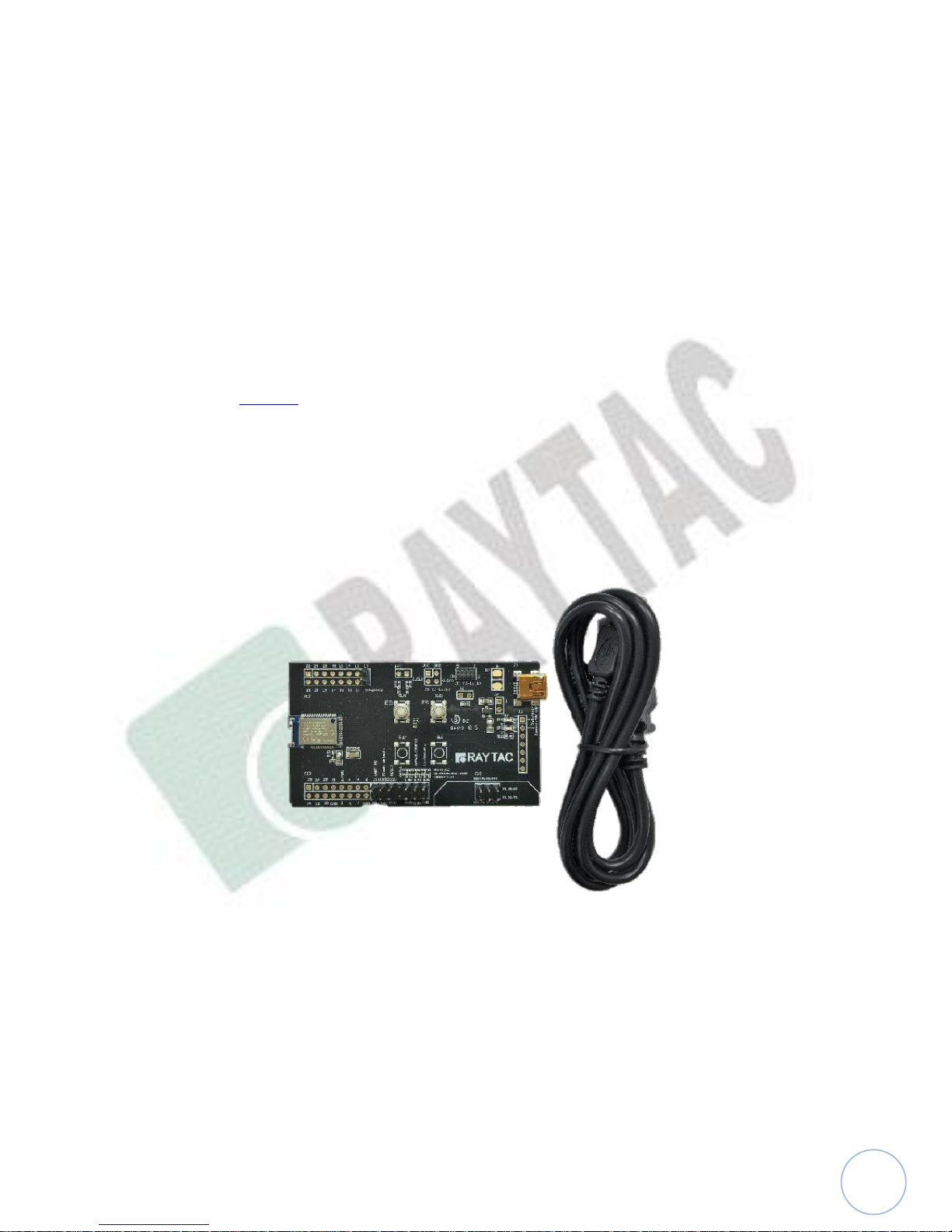
1.1. Contents of the Set
Each set includes MDBT42Q-AT-UART-S x 1 and mini-USB cable x 1. Please contact us if
the set you receive is not complete.

4
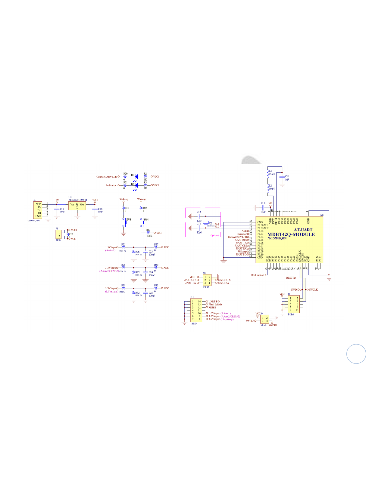
2. Hardware Description
(1) MDBT42Q-AT BLE module based on nRF52810.
(2) 32.768KHz crystal for external LF.
(3) 10uH & 15nH inductor for DC-to-DC mode.
(4) Interface to connect to external MCU.
(5) ADC input for battery detection only. Reference voltage is 0.6V.
Example:
formula: Input Voltage
(6) UART interface for data bridge or AT commands.
(7) Wake-up key.

5
(8) Debug interface, connecting to Nordic’s nRF5X DK.
Important: Please be careful not to “erase” the module during testing. Raytac’s
AT command firmware will not be shared. You may need to send the unit to us
for re-programming when module’s FW is erased.
(9) 3.3V LDO to power up MDBT42Q-AT.
(10) LED for status indicator
(11) USB Power only
6
3. Reference Circuit

7
4. AT Command
4.1. List of supported commands
- Setting of device name
- Choose data rate of 1Mbps or 2Mbps on-air
- Set TX output power in 5 levels.
- Set advertising time
- Set connection interval under Mode 2
- Enable/disable advertising
- Set LED pattern indicating advertising or connecting status
- 7 sets of UART baud rates
- Enable/disable UART flow control
- Enable/disable interface of UART hardware
- Support 8 programmable output GPIO
- Power-down mode for power saving and GPIO wake-up
- Support DC-to-DC and LDO power mode
- Use internal or external 32.768KHz oscillator
- Recover-to-default setting with hardware and software method
- System reset of hardware and software
- Set serial number and retrieve
- Set or retrieve MAC Address
- Retrieve ADC value for battery detection
- Support maximum MTU 247bytes / data payload up to maximum 244 bytes
 Loading...