

Page 1
INSTALLATION AND OPERATING
INSTRUCTIONS
RayTemp™ Hot Water
Energy Management Control
Catalog No: 5000.61B
Effective: 04-15-05
Replaces: 09-01-02
P/N 241098
Page 2

2
Section 1. GETTING STARTED . . . . . . . . . . . . . . . . . . . . . . . . . . . . . . . . . . . . . . .3
THE BIG PICTURE . . . . . . . . . . . . . . . . . . . . . . . . . . . . . . . . . . . . . . . . . . . . . . . . . . . . .3
WHAT COMES WITH THE CONTROLL . . . . . . . . . . . . . . . . . . . . . . . . . . . . . . . . . . . . .4
Section 2. INSTALLING THE CONTROL . . . . . . . . . . . . . . . . . . . . . . . . . . . . . . . . . .4
ATTACHING THE TEMPERATURE SENSORS . . . . . . . . . . . . . . . . . . . . . . . . . . . . . . . . .4
PROVIDING 24 VAC POWER TO CONTROL . . . . . . . . . . . . . . . . . . . . . . . . . . . . . . . . .5
INSTALLATION LAYOUT . . . . . . . . . . . . . . . . . . . . . . . . . . . . . . . . . . . . . . . . . . . . . . . .6
”DIP” SWITCH SETTINGS ON CIRCUIT BOARD . . . . . . . . . . . . . . . . . . . . . . . . . . . . . .7
CONNECTING THE OPTIONAL “ELSA” BRAND MODEM . . . . . . . . . . . . . . . . . . . . . . . .8
USING THE FRONT PANEL TO CHECK SENSORS AND RELAYS . . . . . . . . . . . . . . . . .9
Section 3. CONNECTING A COMPUTER (OR “LAPTOP”) . . . . . . . . . . . . . . . . . . . . .10
BUILDING OR BUYING INTERFACE CABLES . . . . . . . . . . . . . . . . . . . . . . . . . . . . . . . .10
INSTALLING PTT SOFTWARE ON YOUR PC . . . . . . . . . . . . . . . . . . . . . . . . . . . . . . . .11
SIMULATED FRONT PANEL DISPLAY . . . . . . . . . . . . . . . . . . . . . . . . . . . . . . . . . . . . .11
READING LOGGED DATA (Not All Models) . . . . . . . . . . . . . . . . . . . . . . . . . . . . . . . . .12
USING YOUR PC AND MODEM TO CALL A CONTROL . . . . . . . . . . . . . . . . . . . . . . . .12
Section 4. PROGRAMMING . . . . . . . . . . . . . . . . . . . . . . . . . . . . . . . . . . . . . . . . .14
QUICK REFERENCE . . . . . . . . . . . . . . . . . . . . . . . . . . . . . . . . . . . . . . . . . . . . . . . . . . .14
FIRST SCREEN AT POWER-UP . . . . . . . . . . . . . . . . . . . . . . . . . . . . . . . . . . . . . . . . . .17
MANUAL OVERRIDE . . . . . . . . . . . . . . . . . . . . . . . . . . . . . . . . . . . . . . . . . . . . . . . . . .17
VIEW SENSORS AND RELAYS . . . . . . . . . . . . . . . . . . . . . . . . . . . . . . . . . . . . . . . . . . .17
TIME AND DATE . . . . . . . . . . . . . . . . . . . . . . . . . . . . . . . . . . . . . . . . . . . . . . . . . . . . . .17
CELSIUS / FAHRENHEIT SCALE . . . . . . . . . . . . . . . . . . . . . . . . . . . . . . . . . . . . . . . . . .17
ERASE MEMORY / RESET PROGRAM . . . . . . . . . . . . . . . . . . . . . . . . . . . . . . . . . . . . .18
SECURITY PASSWORD (“G” Models Only) . . . . . . . . . . . . . . . . . . . . . . . . . . . . . . . . .18
FRONT PANEL MENU / LOCK . . . . . . . . . . . . . . . . . . . . . . . . . . . . . . . . . . . . . . . . . . . .18
TIME SCHEDULE . . . . . . . . . . . . . . . . . . . . . . . . . . . . . . . . . . . . . . . . . . . . . . . . . . . . .19
SUPPLY TEMPERATURE . . . . . . . . . . . . . . . . . . . . . . . . . . . . . . . . . . . . . . . . . . . . . . .19
RETURN TEMPERATURE . . . . . . . . . . . . . . . . . . . . . . . . . . . . . . . . . . . . . . . . . . . . . . .21
BRANCH TEMPERATURE . . . . . . . . . . . . . . . . . . . . . . . . . . . . . . . . . . . . . . . . . . . . . . .22
RELAY SEQUENCING . . . . . . . . . . . . . . . . . . . . . . . . . . . . . . . . . . . . . . . . . . . . . . . . . .22
SENSOR OVERRIDE TEST . . . . . . . . . . . . . . . . . . . . . . . . . . . . . . . . . . . . . . . . . . . . . .23
SAVINGS TEST SETUP . . . . . . . . . . . . . . . . . . . . . . . . . . . . . . . . . . . . . . . . . . . . . . . . .24
SAVINGS TEST RESULTS . . . . . . . . . . . . . . . . . . . . . . . . . . . . . . . . . . . . . . . . . . . . . . .24
SENSOR CALIBRATION . . . . . . . . . . . . . . . . . . . . . . . . . . . . . . . . . . . . . . . . . . . . . . . .25
LOCATION TEXT . . . . . . . . . . . . . . . . . . . . . . . . . . . . . . . . . . . . . . . . . . . . . . . . . . . . . .26
DATA MODEM SETUP . . . . . . . . . . . . . . . . . . . . . . . . . . . . . . . . . . . . . . . . . . . . . . . . .26
FAX MODEM SETUP AND TEST (“G” Models Only) . . . . . . . . . . . . . . . . . . . . . . . . . . .27
WARRANTY . . . . . . . . . . . . . . . . . . . . . . . . . . . . . . . . . . . . . . . . . . . . . . . . . . .29
SERVICE/RETURN AUTHORIZATION PROCEDURE . . . . . . . . . . . . . . . . . . . . . . . . . . .29
Page 3
3
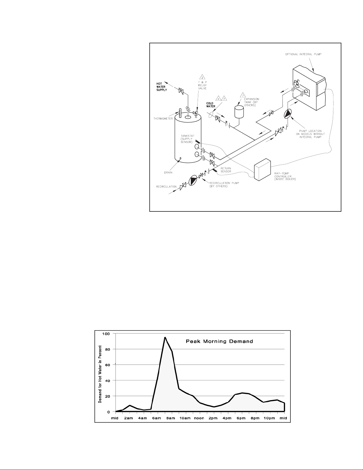
THE BIG PICTURE
This RayTemp control is designed
to make recirculating domestic
hot water heating systems energy
efficient. In a recirculating system, hot water is continuously
pumped throughout the building.
This large loop has many branches which extend to fixtures in the
rooms. It is essentially a giant
radiator which has tremendous
heat loss. By lowering the temperature of this loop it is possible
to dramatically reduce this heat
loss. The trick is knowing when to
lower the temperature without
running out of hot water. With
RayTemp, water temperatures are
automatically scheduled in anticipation of demand. So for the
peak demand in the morning, the water is preheated to a higher temperature. The control does
this automatically by recording a seven day profile of demand, and then it uses this information to
establish setpoints. The control continually adjusts this setpoint to meet demand, always maintaining the lowest temperature which will fully meet user needs. This operation dramatically
lessens costly heat loss, lime deposits, and increases the life of the system. The control is preprogrammed with typical settings, making installation very simple. However, the program values can
be adjusted to accommodate many types of water heating systems. Output control is provided for
up to 4 stages of heat or four heaters. Two standard temperature sensors are connected to the
water heating systems at locations called “Supply”and “Return”.
Section 1. GETTING STARTED
Hot Water Use Throughout the Day
Fig # 8285.1
Page 4

4
WHAT COMES WITH THE CONTROL
Before arriving at the job site to begin the installation, it’s important to first inspect the system and
determine what materials you will need. Some parts are included with the control while the others you will need to provide. Check the following list to verify that you received the following
parts.
1 Control, 10.5” x 8” x 3.5”
1 Panel Cover, Metal, 4” x 7.5”
4 Mounting Screws, 3/4”
2 Temperature Sensors, Copper housing,10 K
Ohm at 25°C
4 Cable Ties,15”, black, -40ºF to 221ºF rated
2 Knockout Connectors, 1/2” to romex
1 Warranty Card
1 Manual
1 24v Grounded Transformer
Cable, twisted pair with shield, stranded, 18
AWG. Belden type 8208 (braid shield) or 9552
(2 twisted pairs, foil shield)
Thermal Insulation Tape
Cable Ties
Wire Nuts
Heat Conducting Paste
Section 2. INSTALLING THE CONTROL
The control should be mounted on a wall, preferably at eye level with AC power as close as possible. Consider the length of cable required for routing along walls, along pipes, and for connecting the temperature sensors.
Notice on the bottom of the control that two of the five knockouts have been removed for routing of cables. If you want to use one or more of the other knockouts, these should be removed
before mounting the control onto the wall.
ATTACHING THE TEMPERATURE SENSORS
To get an accurate reading of the water temperatures, the sensors must be in good thermal contact with the pipe. Follow this procedure when connecting the temperature sensors.
Procedure for Connecting Temperature Sensors to Pipes:
1. Remove any existing insulation.
2. Clean the pipe surface using sandpaper.
3. Apply thermal conducting paste to the pipe surface.
4. Fasten the sensor tightly to the pipe using the black cable tie.
5. Attach 18 AWG shielded cable to the 6 in. leads using wire nuts or electrical tape.
6. Fasten the cable to the pipe using a second black cable tie.
7. Replace the existing insulation or wrap thermal insulation tape around the pipe.
Overlap each turn and DO NOT STRETCH the tape.
Included in the box
Other parts you will need
Page 5

5
On the sensor end, roll the shielding and tape so it will not contact a conductor. On the control
end, the shield should be grounded. Do not ground both ends of the shielding.
Avoid routing wiring on or near other electrical wires, conduit, motors, spark igniters or other
sources of high, intermittent voltage or current. EMI (spikes) can disrupt information flow and
retention.
Procedure for Installing Supply Sensor in Tank:
1. Install sensor into dry well utilizing thermal conductive paste.
2. Install dry well into tank stat opening.
PROVIDING 24 VAC POWER TO THE CONTROL
!!! CAUTION !!!
DO NOT connect power until
all wiring is complete
and checked.
!!! CAUTION !!!
DO NOT connect 120 VAC
to the RayTemp!!!
Resulting damage will
void your warranty.
The RayTemp requires an external power transformer connected at terminals one and two.
Complete and check all wiring before connecting this transformer. The transformer must be rated
for 24 VAC at 16 VA or higher. When 24 VAC power is applied to the control the LCD display will
be blank for a few seconds. During this time the RayTemp is configuring any modem that may be
connected. After this the opening screen appears which identifies the model number, type of control, software version, and copyright notice.
Sensor Connections
Page 6
6
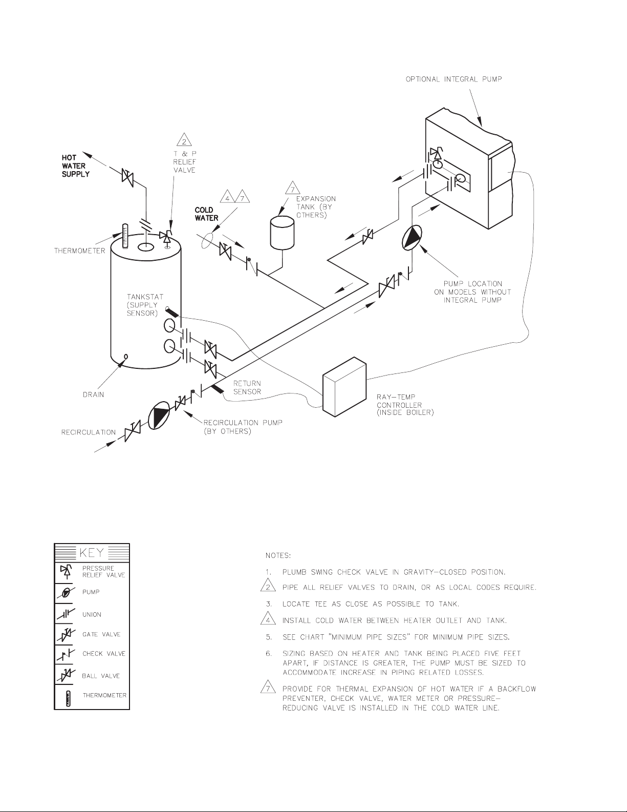
Fig # 8285.2
INSTALLATION LAYOUT
Page 7
7
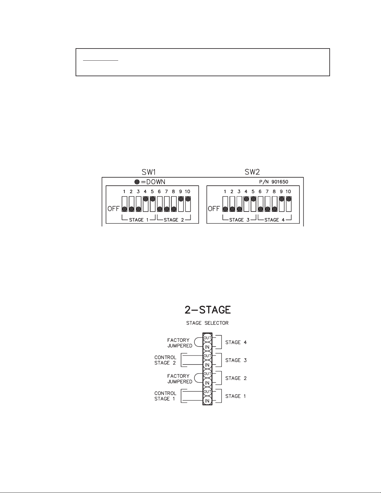
”DIP” SWITCH SETTINGS ON CIRCUIT BOARD
CAUTION: Incorrect DIP switch settings may damage the RayTemp!!!
Make all adjustments with ALL power off.
The four relay outputs are factory set for normally closed dry contacts. These DIP switches are
located behind the terminal block, on the right side. The black dots in the diagram indicate where
to set the 20 switches for normally closed dry contacts. As shown, all four outputs will be the
same. Relay #1 is set on SW1 positions 6 thru 10. Relay #2 is set on SW1 positions 1 thru 5. Relay
#3 is set on SW2 positions 6 thru 10. Relay #4 is set on SW2 positions 1 thru 5.
DIP Switch Setting on Circuit Board
The RayTemp can control up to 4 stages:
• Four single-stage heaters
• Two two-stage heaters
• One four-stage heater
These switches are factory set and should not need adjustment.
Stage Connections on Heater
Remove factory jumpers for 3- and 4-stage connections.
Page 8
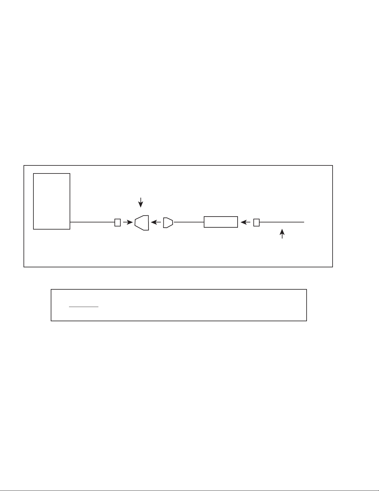
CONNECTING THE OPTIONAL “ELSA” BRAND MODEM
Raypak recommends the ELSA Microlink 56k modem for data communication. This modem will
work with RayTemp and technical support will be provided if this modem is installed with the correct cables. Raypak will not be able to provide support if you use other modem brands or build
your own cables. In either case we strongly recommend that you test the RayTemp/modem connection in your office before installing the system. If possible, plan ahead, and have the phone
line/jack installed about two feet from the heater. Secure the ELSA modem and connect the phone
cable (that comes with the modem) from the wall jack to the ELSA modem jack labeled “Line”.
Connect the RayTemp cable 5-423 from the modem’s 8-pin connector to the RayTemp’s “Serial
to RJ11” adapter then connect the six-line data cable from the adapter to the RayTemp’s six-pin
“RJ11” port (see figure below). Plug in the modem’s power transformer and turn on the power
switch. Testing is covered in the next chapter.
8
CAUTION!
DO NOT connect a live phone line directly to the RayTemp control.
Doing so will damage the internal communication circuit!
RayTemp
RJ11 to 9-pin
Connector
MODEM
Active Phone Line
From Wall
Page 9

9
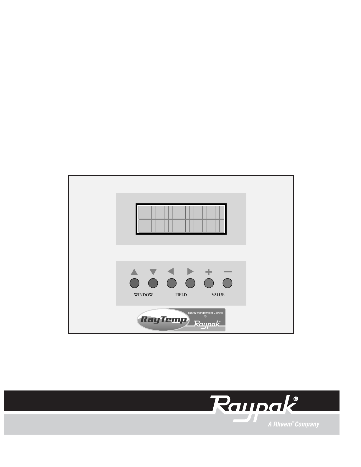
USING THE FRONT PANEL TO CHECK SENSORS AND RELAYS
The RayTemp front panel features an alphanumeric LCD display of four rows by 20 lines. Six keys
are provided to select screens, fields, and make program changes. The up-arrow and down-arr ow
"WINDOW" keys are used to step thru each of the screens. The down-arrow screen selects the
next screen while the up-arrow key selects the previous screen. The left-arrow and right-arrow
"FIELD" keys move a flashing cursor to select different sections within a screen. The plus and
minus "VALUE" keys are used to make changes to a selected field or numeric value. Plus
increases the selected number or selects the next option. Minus decreases the selected number or
selects the previous option.
Using the down-“WINDOW” key select the “SENSORS”
screen and verify that each temperature sensor is measuring the correct value. It’s best to use a reliable temperature
reading device, like a surface thermocouple or a digital
infrared thermometer. Thermostats and mercury ther-
mometers are frequently inaccurate. If the readings disagree by more than two degrees there may be a problem with how the sensor is attached. Also
check for correct wiring at the terminal block.
Next select the “RELAY STATUS” screen and manually
verify that you can turn each water heater or stage on and
off. You do this using the field and value keys. If the heater
does not turn on it may be necessary to increase the
optional secondary mechanical aquastat setting a few
degrees. Use a multimeter to troubleshoot if problems persist. Return to the second screen titled “Master On/Off Mode” and put the control in “Bypass”.
The water heaters will now run using the optional secondary mechanical aquastats until programming of the control has been completed, explained in the next chapter.
SE-Sensors
Supply 136.4
Desired 135.0
Return 128.2
RT-Relay Status
#1 #2 #3 #4
ON OFF OFF OFF
Page 10

10
Section 3. CONNECTING A COMPUTER
This section explains how to connect your personal computer to the RayTemp. Once connected,
you can view all of the front panel screens covered in the previous section. You can also retrieve
the recorded data and view color graphs of temperature and demand profiles. "PTT" is the optional software tool for your personal computers that works with RayTemp controls. It simulates the
front panel and retrieves logged data. PTT software and interface cables are available directly fr om
Raypak. The computer must be able to accept a serial (RS-232) cable.
Wiring pin assignments are provided below for building your own cables.
CAUTION! Never plug a telephone line into the RJ-11 connector! The contr
ol may be damaged.
BUILDING OR BUYING INTERFACE CABLES
The following cables are available from Raypak:
Description Part #
PTT Software
Communication for Windows PC to 70 series control
PTT
Direct Connect Communication Cable
Connects a 70 series control to a PC
5-424
Modem Communication Cable
Connects a 70 series control to a modem
5-423
Ground 6 5 Ground
Program 2 4 Program
Receive 5 3 Transmit
Transmit 4 2 Receive
Ground 6 7 Ground
Receive 5 3 Transmit
Transmit 4 2 Receive
RayTemp to PC/Modem Pin Assignments
RJ-11 Wire color codes:
White = 1
Black = 2
Red = 3
Green = 4
Yellow = 5
Blue = 6
RJ-11 Pin
(RayTemp)
DB-9 Pin
(PC/Modem)
RayTemp to Modem Pin Assignments
RJ-11 Wire color codes:
White = 1
Black = 2
Red = 3
Green = 4
Yellow = 5
Blue = 6
DB-25 Pin
(Modem)
RJ-11 Pin
(RayTemp)
Page 11

11
INSTALLING PTT SOFTWARE ON YOUR PC
This section provides instructions for installing PTT communication software. First insert the PTT
CD into your CD drive. Double click on the folder Ptt258 then double click on Install. The PTT
communication software will then be installed on your C:\GBX subdirectory. To run PTT, type PTT
(then press enter) from the C:\GBX subdirectory. Within a few seconds the main menu, software
version I.D., and copyright notice will appear. Use the arrow keys and enter key to select items
from the menu bar at the top of the screen. First check the default options by selecting the
“Options” menu item. There are several items that can be changed. Most PC’s have several communication ports. Port 1 is usually for direct connections and port 2 is usually used for internet
modems. The second option sets the communication speed. The default speed for RayTemp is
9600 Baud. Next is the print quality, 1 = draft mode (fast), 2 = medium, 3 = high resolution (but
slow). Press Ctrl-Enter to save your selection.
SIMULATED FRONT PANEL DISPLAY
This “Laptop” selection from the menu bar opens up a window on the PC screen to receive formatted data and program information sent by a RayTemp control, connected at the serial (RS232)
port. From the main menu select "LapTop" and press enter. Connect the cable to the
RayTemp control and press F1 to begin communication. The screen and keyboard will operate
similar to the front panel but with enhanced features to take advantage of the larger screen. This
table shows the function keys for accessing all RayTemp display and programming features.
These keys apply to both the PC and LapTop display, except as noted. A screen saver clears the
display after five minutes. Press F1 thru F5 to restore the screen.
Key Action
F1 Press two keys for direct access to any screen
F2 Select next screen
F3 Select previous screen
F4 Increase program value
F5 Decrease program value
SPACE Select next field in a screen
BACK Select previous field in a screen
SPACE
F6 Activate full-screen viewing (PC)
SHIFT Restore LapTop window (PC)
F6
Page 12

12
READING LOGGED DATA
Under the "History Report" menu item, logged data can be retrieved from a RayTemp control,
saved to a disk file, viewed graphically on screen, or output to a printer. To retrieve history, connect the RayTemp serial cable between the RayTemp and your laptop PC. Then select "Retrieve".
The RayTemp will transmit logged data to your PC. This takes about one minute at 9600 Baud. A
status window will be present while the data is being received. The logged data consists of a
report, seven detailed daily graphs (Monday thru Sunday), and twelve monthly graphs (January
thru December). A menu will appear from which you can view any of these graphs. This data will
be automatically saved to a disk file, based on the file name in the report data. PTT creates a
unique name for each file by setting the last position of the file name prefix. The codes are 0 thru
9 and then A thru Z. For examples REDLION.GIX will be saved as REDLION0.GIX, REDLION1.GIX,
REDLION2.GIX, etc.
To view an existing history file select "Display", and select a file by pressing enter. After the
graphs are prepared, a window will appear from which you can select any daily graph or
monthly graph to view on the screen.
The "Print" option under "History Report" allows you to send site reports and graphs to any supported printer. When this item is selected a directory of data files will appear. Point to a file using
the arrow keys then press enter to select the file. A check mark will appear. Place check marks next
to all data file you wish printed, then press Ctrl-Enter to continue. A second screen will appear for
selecting graphs within a report. Place a check mark (press enter) by each graph you want included in the printed report. Press ESC to start printing.
USING YOUR PC, PTT AND MODEM TO CALL A CONTROL
If this is your first attempt at modem communication with a RayTemp control we recommend that
you first try everything in your office using two phone lines. Connect the RayTemp to an external
modem and connect this modem to one line and your PC modem to another. Next, configure the
RayTemps modem as described in the previous section. Make sure that the modem’s auto answer
“AA” light is on. Also, buy a modem cable from RayTemp - at least for your first installation. This
will prevent 80% of your possible problems.
To “get on-line” with the RayTemp, start the PTT software and select “Options” from the menu
bar at the top of the screen. Enter the port number (usually 1 or 2) for the modem connected to
your PC and make sure the speed is set to 9,600. Then press Ctrl-Enter and select “TechTerm”
from the menu bar . A set of seven windows will appear. Start entering the phone set up commands:
“ATE1” “ENTER” Return should show “OK”. If not, re-enter.
“AT&F” “ENTER” Return should show “OK”.
“AT&D0” (zero) “ENTER” Return should show “ok”.
For example, to place a call, dial “ATDT5551212” and wait for a “Connect” message (replace the
“5551212” with your actual phone number). If the screen is blank, type “ATE1” and try again.
Note: The “Modem” section on the menu bar does not work with the RayTemp. Once you see
the “Connect” message in the TechTerm window press F1 and then F6 to begin communication.
Page 13

13
To end the modem session, select the following screen in the LapTop window.
This screen is used to terminate the call. The RayTemp will
actually terminate the phone connection and prevent the
modem from answering the phone for about five minutes.
The message "CARRIER LOST" will appear in the LapTop
window. Another call may then be placed to contact
another RayT emp sharing the same phone line. Always use
this method to end a modem call to the RayTemp in shared phone-line applications. It's also a
good idea to have an actual telephone connected to the line. Make sure a dial tone is present to
verify that the call has been terminated.
MC-Modem Control
F4 to Hang-Up
Page 14

14
Section 4. PROGRAMMING
QUICK REFERENCE
This section describes all the programmable features of the control. You make program changes
from the front panel or by using a laptop. For information on connection with a LapTop using PTT
software, refer to the previous section. The following keys provide access to all RayTemp display
and programming features. These keys apply to the front panel or LapTop display as shown
below. A screen saver clears the display after five minutes on the LapTop. Press F1, then F6 to
restore the screen.
Front Panel
Key
Laptop
or PC Key
Screen Selected
WINDOW
UP & DOWN
F1
Returns to first screen, then press two
keys for direct access to any screen as
listed on the next screen
WINDOW DOWN F2 Select next screen
WINDOW UP F3 Select previous screen
VALUE+ F4 Increase program value
VALUE- F5 Decrease program value
FIELD RIGHT SPACE Select next field in a screen
FIELD LEFT BACKSPACE Select previous field in a screen
F6
Activate full-screen viewing (PC with
PTT only)
SHIFT F6
Page 15

15
Screen code and description, in sequence of appearance See page
FM PRODUCT IDENTIFICATION - Model, type, and version 17
SE SENSORS - Displays temperature of each standard sensor 17
OS OPTIONAL SENSORS - Displays other sensors 17
RT RELAY TEST - On/Off relay status and manual override 17
ST SENSOR TEST - Simulates sensor temperatures 23
RM RUN TIME METERS - Total on-time for each heater or stage
DL DETAIL LOG - Shows history values for seven days
TL TREND LOG - Shows history values for one year
CK CLOCK - Display and set time and date 17
TS TIME SCHEDULE - Seven day, 20 schedule, time clock 19
ER ERASE/RESET - Selective clear or restart 18
MC MODEM TEST - Terminate call or test modem or fax 28
PD PERFORMANCE DATA - Savings Analysis 24
DN TEXT - Company Name 26
PN TEXT - Property Name 26
SL TEXT - Site Location 26
FN TEXT - Disk File Name 26
MS TEXT - Modem Setup 26
SH TEXT - Modem Disconnect 26
AD TEXT - Pager Dial-Out 26
FD TEXT - Fax Dial-Out 27
PW TEXT - Security Password 18
PM TEXT - Front Panel Menu 18
RL TEXT - Relay Logic (1-12) 23
T1 SELECT - Supply Sensor Offset 25
T8 Not used for this model
C0 SELECT - Maximum Supply Temperature 19
C1 SELECT - Minimum Supply Temperature 19
C2 SELECT - Outside Temperature for Maximum Supply 19
C3 SELECT - Outside Temperature for Minimum Supply 19
C4 SELECT - Night Setback at Maximum Supply 19
C5 SELECT - Night Setback at Minimum Supply 19
C6 SELECT - Morning Boost at Maximum Supply 20
C7 SELECT - Morning Boost at Minimum Supply 20
Screen codes in Boldface are described in detail on the pages listed.
Page 16

16
Screen Code and Description - continued See page
HL SELECT - Supply High Limit 20
LL SELECT - Supply Low Limit 20
DW SELECT - Demand window in minutes 20
DM SELECT - Demand % for maximum temperature 20
DA SELECT - Demand % for ASL strategy 20
R0 SELECT - # of Room Sensors Installed 21
R1 SELECT - Desired Daytime Room Temperature 21
R2 SELECT - Desired Nighttime Room Temperature 21
E0 SELECT - Recovery sensor installed
E1 SELECT - Minimum recovery time
E2 SELECT - Recovery sensor response
B0 SELECT - # Branch sensors installed 22
S0 SELECT - Days to Acclimate Residents 19
S1 SELECT - Day of Month for Savings Test 24
S2 SELECT - Old Maximum Supply Temperature 24
HS SELECT - # of water heaters 22
SP SELECT - # stages per heater 22
SQ SELECT - Alternating Relay Sequencing 22
US SELECT - Use 24Volt on/off sensing 22
DD SELECT - Deadband (also known as hysteresis) 23
D1 SELECT - Temperature Delay Between Stages 23
LK SELECT - +- Keys Locked 18
CU SELECT - Celsius Units 17
LG SELECT - Access Data Logger #
XX SELECT - Fax Graph Max Temp 27
XN SELECT - Fax Graph Min Temp 27
XM SELECT - Fax on Day Of Month 27
XW SELECT - Fax on Day of Week 27
XH SELECT - Fax on Hour of Day 27
MO SELECT - Operating Mode 17
BA SELECT - Communication BAUD Rate 26
NI SELECT - Network address number
Page 17

17
FIRST SCREEN AT POWER-UP
FM PRODUCT IDENTIFICA
TION. This screen displays the model number, type of control,
copyright notice, and software version number. Press F2 to select the next screen in order, or press
two keys for direct access to any one of the following screens.
MANUAL OVERRIDE
MO SELECT (MODE)
- Operating Mode selects one of three states of operation. In Run mode
all control functions are operational. In Bypass mode, control is returned to the mechanical controls if provided. In Off mode all systems are shut of f and remain of f indefinitely. In all three modes
the RayTemp data logger and modem/fax functions continue to operate.
VIEW SENSORS AND RELAYS
SE SENSORS
- Displays the setpoint and current temperature reading from each primary tem-
perature sensor.
OS OPTIONAL SENSORS - Displays current temperature reading from each optional temper-
ature sensor.
RT RELAY TEST - Displays on/off status of each relay output. Press SPACE or BKSP to a select
relay (flashes). Then press F4 to test on, F5 to test off. To return control to the RayTemp, press
SPACE or BKSP until no locations flash. The RayTemp will automatically retake control if no manual testing takes place for five minutes.
TIME AND DATE
CK CLOCK
- Displays present time and date. To set, press SPACE, F4 and F5.
CELSIUS / FAHRENHEIT SCALE
CU SELECT
- For Celsius units, select Yes and all process and program values will be displayed
in the Celsius temperature scale. (The default setting of No selects the Fahrenheit scale.)
Page 18

18
ERASE MEMORY / RESET PROGRAM
ER ERASE/RESET
- Press F4 or F5 to select which item will be reset or cleared, then press
CTRL+E to confirm each action.
Set BAUD Rate will reconfigure the serial port according to the BA screen. If the speed is differ-
ent, then reset the BAUD rate on your LapTop (garbage characters will appear).
Zero Run Meters set all run-time meters to zero.
Erase History sets all 7-day and 365-day history to -30.
Reset Program sets all program values to factory default values.
Erase All does all the above (requires 30 seconds).
SECURITY PASSWORD
PW TEXT
- Security Password This screen is used to prevent unauthorized access to the
RayTemp, either by modem or direct connection. To use this feature, select a password up to 40
characters and enter it on this screen. Then, all future communication with the control will be
blocked until this password is entered. A screen will appear asking for the password. Make a note
of your password, since you will not be able to access the control without it! By default, no password is required. To disable password protection erase all text in this field.
FRONT PANEL MENU / LOCK
PM TEXT
- Front Panel Menu This option provides for limited access by the building care-
taker to a fixed set of screens from the front panel. By default, 13 of the most commonly used
screens are accessible from the front panel. They are identified in this screen by their two character access code. This line of text can be modified to select a custom set of screens, in any order,
up to 13 screens. If the first character on this line is a space (' ') then this menu system will be disabled and all screens will be accessible from the front panel. To gain access to all of the screens
using only the front panel, press both VALUE keys while in the PRODUCT IDENTIFICATION
screen. This enters a first character space as described above.
LK SELECT - +- Keys Locked When Activated This option prevents changing of pro-
grammed values from the RayTemp front panel + and - keys.
WARNING: This option cannot be deactivated from the control itself. Deactivating this screen
requires either (1) a connection to a PC running the PTT software, or (2) returning the control to
the manufacturer to have them reset this option.
Page 19

19
TIME SCHEDULE
TS TIME SCHEDULE
This is a seven-day time clock. Each line is a program for starting a new
period (such as Night) on a day (such as M-F) and at a time (such as 6:00 am). Up to 20 lines can
be displayed or programmed using the SPACE, F4 and F5 keys. Periods end automatically when
a new one starts. The day codes are M-F (Monday thru Friday), S-S (Saturday and Sunday), F-S
(Friday thru Sunday), and --- (no days). The recommended setting for intial programming is --(no days) on all settings. Changes can be made to accommodate individual schedules.
SUPPLY TEMPERATURE
The RayTemp control strategy closely matches water temperature to demand as hot water use
varies throughout the day. The setpoint is adjusted based on a demand profile which is recorded
for the last seven days. The RayTemp scans this profile and adjusts the setpoint in anticipation of
demand. This strategy is complemented with a seven-day time clock which can provide fixed temperatures during certain hours for special requirements, such as laundry.
C0 SELECT - Maximum Regular Temperature During Regular periods the desired temper-
ature will be set between (screen) C0 and C1 according to demand. The time clock schedule determines when Regular takes effect. Default Temp 140°F.
C1 SELECT - Minimum Regular Temperature The supply temperature will not be set below
this value during Regular periods. Default Temp 130°F.
C2 SELECT - Maximum Peak Temperature C2 and C3 become the new maximum and min-
imum temperatures when the time clock schedule is in Peak mode. Default Temp 140°F.
C3 SELECT - Minimum Peak Temperature During peak periods the supply temperature will
not be set below this value. Default Temp 130°F.
C4 SELECT - Maximum Laundry Temperature C4 and C5 will be the maximum and mini-
mum temperatures in effect if Laundry is activated by the seven-day time clock. For laundry needs
C4 and C5 will usually be set to the same value. Default Temp 140°F.
C5 SELECT - Minimum Laundry Temperature See C4 above. Default Temp 140°F.
Page 20

20
C6 SELECT - Maximum Extra Temperature C6 and C7 are an extra set of temperatures
which can be scheduled for any purpose. They will become the maximum and minimum supply
temperature if the Extra schedule is activated by the time clock. Default Temp 140°F.
C7 SELECT - Minimum Extra Temperature See C6 above. Default Temp 130°F.
HL SELECT - Supply High Limit If the recovery temperature or the return temperature is very
low, the RayTemp may need to take the supply temperature above the programmed maximum.
Regardless of any conditions, the RayTemp will not take the supply or any branch temperature
above this high limit value. If the supply temperature exceeds this value by 10°F then alarm dialout will be activated. Default Temp 140°F.
LL SELECT - Supply Low Limit The RayTemp will not schedule the supply temperature lower
than this value (or programmed minimum). If the supply temperature drops 10°F below this value
then alarm dial-out will be activated. Default Temp 120°F.
DW SELECT - Demand Windows in Minutes This value sets the time period of demand
history to be used in calculating desired temperature. The default value should yield a smooth profile. Decreasing this value will cause faster response to changing demand at the risk of instability.
Increasing this value will produce a very smooth desired temperature profile, however the temperature may not rise quickly enough during peak demand periods. The range is from 10 to 90
minutes. Default Value 40.
DM SELECT - Demand % for Maximum Temperature This feature provides a means of
increasing temperature in oversized systems which show very little demand. Example: Set to 50%.
When demands of 50% or more are encountered, the desired temperature will be at pr ogrammed
maximum. Below 50% the desired temperature will be proportional between maximum and minimum programmed values. The range is from 10 to 100 percent. Default Value 100.
DA SELECT - Demand % for ASL Strategy This feature automatically adapts to manual
changes in the optional, secondary aquastat setting which may occur after installation. This
ensures continued savings even if the aquastat is lowered. (ASL is an acronym for Aquastat Set too
Low). The strategy works by lowering the setpoint temperature until the RayTemp has regained
control. For each 24-hour period that demand exceeds this DA percent, the setpoint is lowered by
5°F. Then for each 24-hour period that heater demand is less than one half of DA, the setpoint is
increased by 1°F until the original value is restored. The default value is 70%. The PERFORMANCE
DATA screen titled Temp Reduced by ASL Strategy will show a value other than zero if this strategy is in effect. Default Value 70.
Page 21

21
RETURN TEMPERATURE
The return sensor is used to compensate for seasonal changes in loop heat loss. The strategy may
raise the supply/branch temperature in cold weather to ensure that the last rooms on the loop
have hot enough water even during low demand periods.
R0 SELECT - Return Sensor Installed Select YES if this sensor is connected, otherwise select
NO. Default is YES.
R1 SELECT - Minimum Return Temperature If the return temperature drops below this
value then the return sensor strategy will be activated. Above this value, the strategy will have no
effect on desired temperature. Default Temp 108°F.
R2 SELECT - Return Sensor Response This is a multiplier which increases the desired tem-
perature as the return temperature drops. Example: desired = 130, r eturn = 100, R1 (above) = 102,
R2 = 5. The desired temperature will be increased to 140 = 130 + (102-100) X 5. Default Value
is 1.
Page 22

22
BRANCH TEMPERATURE - NOT USED
B0 SELECT - # of Branch Sensors Installed
Not used.
RELAY SEQUENCING
HS SELECT - # of Heaters
Enter 1 thru 4 for the number of heaters connected to relay out-
puts 1 thru 4. This allows the RayTemp to correctly sequence heaters and record demand.
SP - SELECT - Stages Per Heater Enter the number of stages in each heater, from 1 to 4.
SQ - SELECT
Firing Options Four options for stage sequencing are available. Select number 1, 2,
3, or 4 as follows:
#1 No Lead/Lag: Stage 1 of heater #1 always fires first. The
remaining stages and heaters will fire in order as demand
increases.
#2 24-Hour Rotation: At midnight each day, the firing order is
rotated to the next heater. This distributes the work load
equally among all heaters.
#3 Lead/Lag & Rotate: With this option, heater #1 always fires
first, then the remaining heaters fire in rotation. Since some
flue designs require heater #1 to fire first; this option meets this
requirement while still providing limited rotation.
US SELECT - Use 24volt on/off sensing. Do not use.
Page 23

23
DD SELECT - Differential Increasing DD lengthens the heater burn cycle; decreasing DD
improves temperature stability. For instance: desired=140, deadband=1, heater turns off at 141
and on at 139. This deadband applies equally to all stages.
D1 SELECT - Temperature Delay Between Stages (In addition to differential setting)
This value causes successive output stages to come on according to the deviation to target temperature. D1 activates additional heaters or stages as demand increases. For example with a setpoint of 140°F and a temperature delay of 1°F, stage 1 will fire at 140, stage 2 at 138, stage 3 at
136, etc., assuming 2°F deadband.
RL TEXT - Relay Logic (1-12) The default value is ++++++++++++. NOTICE: If you select
minus (-) and the RayTemp loses power or fails, then the heater or pump will remain off!!! Edit
text with SPACE, BACKSP, F4, and F5 to return to a plus setting.
SENSOR OVERRIDE TEST
ST SENSOR TEST
This feature allows you to simulate any sensor temperature and observe the
affect on desired temperature and relay sequencing. Press SPACE or BKSP to select a sensor, then
override the actual sensor temperature by pressing F4 or F5. Each key stroke changes the temperature by one degree F. Press Shift+F4 or Shift+F5 to adjust the temperature by one-tenth of a
degree (works with PTT). You can change any or all sensors values and then look at other screens.
While in this mode all temperature values will be frozen at the values you select. To restore the
actual sensor values, press SPACE or BKSP until Inactive ###.# appears. The RayTemp will automatically restore actual sensor values 30 minutes after exiting this screen.
Page 24

24
SAVINGS TEST SETUP
S1 SELECT - Day of Month for Savings Test
Selecting a value other than 0 (default) activates the flip-flop savings test. This test will cause a simulation of conditions before the RayTemp
was installed - for 24 hours on the day specified every month. The test will run only on the day
of month selected AND on multiples of that day. Examples: Values 16 thru 28 will run test for that
day only. Value 14 will run test on day 14 and 28. Value 5 will run test on day 5, 10, 15, 20, 25,
and 30. One day of testing may not yield accurate results, while four or more days of testing will
significantly cut into savings. The recommended value is 14 (2 test days).
S2 SELECT - Old (Maximum) Supply Temperature Enter the supply temperature prior to
installing the RayTemp if you wish to use the Acclimate feature or Savings Test feature (above). If
the preexisting control operated at a fixed temperature enter that value here and also in the next
screen.
SAVINGS TEST RESULTS
PD PERFORMANCE DATA
From this screen press F4 or F5 to view savings analysis statistics
as described below:
Average Energy Savings % Displays the average energy savings in percent during the last 365
days. This can be used to determine actual dollars savings and payback period. This feature will
not operate unless a day of month for savings test is selected. A flip-flop test then is activated
which alternates between RayTemp mode and baseline mode (which has higher energy consumption).
Baseline Heater Run Time % Displays average heater demand during Baseline mode for the last
365 days (simulating a fixed setpoint control). This is diagnostic information used in calculating
savings.
RayTemp Heater Run Time % Displays average heater demand for all heating days except baseline days during the last 365 days. This is diagnostic information used in calculating savings.
Days in Baseline Mode Shows the number of days during the last year that RayTemp was in baseline mode - simulating the preexisting fixed setpoint control.
Days in RayTemp Mode Shows the number of days during the last 365 days when there was
demand for heat and baseline mode was not in effect.
Page 25

25
Total days in service displays the total operating days in modes RUN, BYPASS, and OFF. When 24
VAC power is absent this value will not increase however the clock will still operate.
Number of power interruptions value is incremented each time 24 V AC power is removed or interrupted.
ASL strategy temp reduced a value other than zero indicates that the RayTemp has reduced its setpoint temperature by this amount. This was done to regain control because the existing aquastat
setting was lowered.
SENSOR CALIBRATION
The following screens allow you to introduce a fixed positive or negative offset to any temperature input. You will not normally need to make any adjustments here since RayTemp sensors and
electronics are very accurate. The default values in these screens compensate for a small self-heating affect on the thermistor sensor. For small-mass base thermistors, the offset is -2.5°F. For thermistors mounted in housings or attached to a pipe with thermal paste the offset is -1.5°F.
You can check measurement accuracy of RayTemp using fixed resistors and the resistance/temperature chart published by Independent Energy. Before doing this first set each offset below to
zero.
T1 SELECT - Supply Offset for sensors 1 thru 7
T8 SELECT - Supply Offset for sensors 8 thru 15. Not used for this model
Page 26

26
LOCATION TEXT
DN TEXT - Company Name
Accepts entry of company name into RayTemp memory. This
information will appear in installation reports. Edit with SPACE, BACKSP, F4, and F5.
PN TEXT - Property Name Accepts entry of site name into RayTemp memory. This informa-
tion will appear in installation reports. Edit with SPACE, BACKSP, F4, and F5.
SL TEXT - Site Location Accepts entry of city and state names into RayTemp memory. This
information will appear in installation reports. Edit text with SPACE, BACKSP, F4, and F5.
FN TEXT - Disk File Name Accepts entry of a DOS file name into RayTemp memory. The
installation report and graphs will be saved in a file under this name (seven characters maximum).
Edit text with SPACE, BACKSP, F4, and F5. Only needed when logging data to a connected
LapTop.
DATA MODEM SETUP
BA SELECT - Communication Baud Rate
For direct connect, use 9600 Baud. For modem
use, set at required 9600. Speed is activated only during power-on reset or from ER ERASE/RESET
screen.
MS TEXT - Modem Setup Accepts entry of AT command string into RayTemp memory. If a
modem is installed, the RayTemp will transmit this command string to configure your modem. Use
the Hayes-compatible modem manual for information about the AT commands. This text will also
appear on installation reports. Edit text with SPACE, BACKSP, F4, and F5. Once set, write down
at command string.
SH TEXT - Modem Disconnect Accepts entry of AT commands into RayTemp memory. If a
modem is installed the RayTemp will transmit this command to the modem to terminate the phone
connection and prevent the modem from answering another call.
AD TEXT - Pager Dial-Out Accepts entry of AT commands into RayTemp memory. If a
modem is installed the RayTemp will transmit this command to the modem if an alarm condition
exists. For example, commands can be selected to dial a pager and display a code to identify the
calling RayTemp unit. Consult your Hayes-compatible modem manual for more information about
AT commands. This text will appear on installation reports. Edit text with SPACE, BACKSP, F4, and
F5.
Page 27

27
FAX MODEM SETUP AND TEST
FD TEXT - Fax Dial-Out
Use this screen to enter the phone number of the fax machine which
is to receive fax alarm messages, installation reports, and/or graphics. Example "ATDT5551212".
Edit text with SPACE, BACKSP, F4, and F5.
XX VALUE - Fax Graph Max Temp This value sets the highest value of the Y-axis tempera-
ture scale for all faxed graphs. This item is unrelated to PC graphics. Autoscaling is not supported.
XN VALUE - Fax Graph Min Temp This value sets the lowest value of the Y-axis tempera-
ture scale for all faxed graphs. This item is unrelated to PC graphics. Autoscaling is not supported.
XM VALUE - Fax on Day of Month A complete installation report with graphics of logged
data can be automatically faxed, once a month, to any group III fax machine. This value sets the
day of the month to transmit this data. The report consists of seven pages. The first two pages
give all program values and performance data, such as percent savings. The next three and onehalf pages are detailed graphs for the last seven days. The last one and one-half pages are trend
graphs for the last 12 months. The default day of zero disables this function.
XW VALUE - Fax on Day of Week Detailed graphs of logged data for the last seven days
can be automatically faxed, once a week, to any Group III fax machine. This value sets the day of
the week to transmit this data.
Value Transmit Day Graphs
0 None None
1 Monday Last 7 days on 3 1/2 pages
2 Tuesday Last 7 days on 3 1/2 pages
3 Wednesday Last 7 days on 3 1/2 pages
4 Thursday Last 7 days on 3 1/2 pages
5 Friday Last 7 days on 3 1/2 pages
6 Saturday Last 7 days on 3 1/2 pages
7 Sunday Last 7 days on 3 1/2 pages
8 Every Day Yesterday full size on 1 page
Page 28

28
XH VALUE - Fax on Hour of Day This option sets the time of day to transmit fax reports. It
works in conjunction with XW and XM, above. The RayTemp will attempt to fax the specified data
on the specified day (above) and at this specified time. Military time is used with values of 0 to
23, 12 is noon. If the first attempt is not successful then the RayTemp will make two more
attempts at 10 minute intervals. Where multiple RayTemps are calling into one fax machine it's
very important to set each control to a different day and/or time, otherwise some controls may
always get a busy line.
MC MODEM TEST This screen provides for modem testing and manual fax transmission of
reports and graphics. The following table describes the options in this window. These options are
selected using the FIELD keys and activated by pressing the PLUS key. The "Status:" line in this
window reports progress of the action as shown in the second table below.
Option Transmit Function Pages
Setup "Modem Setup" command to modem N/A
Disconnect "Modem Disconnect" command to modem N/A
Pager Alarm "Pager Dial-Out" command to modem N/A
Fax Alarm Warning message, identifies location 1
Fax Report Installation report 2
Fax Year Trend graphs for last 12 months 3
Fax Month Trend graph for the 4 month period 1
Fax Week Detailed graphs for the last 7 days 4
Fax Today Detailed graph for one day, today 1
Fax Yesterday Detailed graph for one day, yesterday 1
Fax All Report and all graphs 7
Status Description
(blank) No Activity
Sending Transmission in process. This message may remain for up to 12
minutes depending on the action selected
OK Data modem or fax modem has successfully completed the
operation. Failed data modem or fax modem did not reply or was
unable to complete the action requested
Failed Data modem or fax modem did not reply or was unable to complete
the action required
Note: The "Pager Alarm" action will always reply "Failed" because the modem does not connect
with another modem. In this screen, no actions will retry in the event of transmission failure (press
plus (+) again). However when actual alarm conditions occur or when reports are scheduled for
automatic transmission the RayTemp will retry. Up to three attempts will be made, per day, at 10minute intervals.
Page 29

29
WARRANTY
The Raypak RayTemp Control is warranted to be free from defects in material and workmanship for a period of one year from the date of installation or fourteen months from date of shipment, whichever occurs
first.
THE FORGOING WARRANTY IS IN LIEU OF AND EXCLUDES ALL OTHER WARRANTIES NOT EXPRESSLY SET FORTH HEREIN, WHETHER EXPRESSED OR IMPLIED BY OPERATION OR LAW OR OTHERWISE,
INCLUDING BUT NOT LIMITED TO ANY IMPLIED WARRANTIES OF MERCHANTABILITY OF FITNESS.
At its option, Raypak will repair or replace any RayTemp Control which fails to conform to this warranty.
Repair or replacement shall be the sole remedy of the buyer under this warranty, and Raypak shall not be
liable for any installation, removal or reinstallation costs, or for any damage and/or injury to building, contents, products or persons by reason of the installation of the RayTemp Control, or for incidental or consequential losses, damages or expenses, including loss or profits, directly or indirectly arising from this sale,
handling or use of the goods, or from any other cause relating thereto, whether such claims are for breach
of warranty or negligence.
Any claim by buyer with reference to the Raypak RayTemp Control sold hereunder for any cause shall be
deemed waived by buyer unless submitted to Raypak in writing within thirty (30) days from date buyer discovered, or should have discovered, any claimed breach. To obtain service under this warranty, call or write:
RAYPAK, INC.
2151 Eastman Avenue
Oxnard, CA 93030
805-278-5300
SERVICE/RETURN AUTHORIZATION PROCEDURE
Raypak will not accept a returned unit unless the buyer has received prior authorization to return the unit.
If a problem is suspected with the RayTemp control while under warranty, the owner or operator should
first call the installing dealer. The dealer should contact Raypak at the above phone number for return
authorization. Required information: name of site, location, serial number, reason for return. An authorization number will be issued. Repaired or replacement equipment will be returned to you prepaid.
Warranty Card
Please return this card within 30 days of installation to initiate your warranty and enable us to better serve you
Control Model: ___________________________________ Date Purchased: __________________________________
Control Serial Number: _____________________________ Date Installed: ____________________________________
Water Heater Model Number:_______________________ Water Heater Serial Number: ________________________
Company Name: __________________________________ Contact Name: ____________________________________
Company Address: ________________________________ City: _________________ State:_____ Zip Code:________
Installation Location: _________________________________________________________________________________
Installation Address: _______________________________ City: _________________ State:_____ Zip Code:________
Type of Property: Apt/Condo_______ Hotel/Motel_______ Other ________
RayTemp Dealer: __________________________________ Address: _________________________________________
City: _____________________ State: ______ Zip Code: ______________
Page 30

Raypak Inc., 2151 Eastman Avenue, Oxnard, CA 93030 • (805) 278-5300 • (800) 872-9725
www.raypak.com
 Loading...