

Page 1
T
-S e rie s
Installation a nd operation
instructions
En glis h
Date: 08-2012
Documen t numb e r: 81 33 8-3-EN
© 20 12 Ra ymarine UK Limited
Page 2

Page 3

Trademarksandpatentsnotice
Autohelm,hsb
2
,RayTechNavigator ,SailPilot,SeaT alk,SeaT alk
NG
,SeaTalk
HS
andSportpilotareregisteredtrademarksofRaymarine
UKLimited.RayTalk,Seahawk,Smartpilot,PathnderandRaymarineareregisteredtrademarksofRaymarineHoldingsLimited.
FLIRisaregisteredtrademarkofFLIRSystems,Inc.and/oritssubsidiaries.
Allothertrademarks,tradenames,orcompanynamesreferencedhereinareusedforidenticationonlyandarethepropertyof
theirrespectiveowners.
ThisproductiscoveredbyoneormoreofUSPatentNos:7470904;7034301;6812465;7470902;6929410andotherpatents
pending,ordesignpatentspending.
FairUseStatement
Youmayprintnomorethanthreecopiesofthismanualforyourownuse.Youmaynotmakeanyfurthercopiesordistributeorusethe
manualinanyotherwayincludingwithoutlimitationexploitingthemanualcommerciallyorgivingorsellingcopiestothirdparties.
Exportcontrol
T303,T403,T453,T463,T470SCandT473SCthermalcamerasarecontrolledbyUSexportlaws.
Therearespecialversionsofthesystemthatareapprovedforinternationaldistributionandtravel.PleasecontactRaymarinecustomer
supportifyouhaveanyquestions.
ContactdetailscanbefoundontheRaymarinewebsite,www.raymarine.com.
ExportAdministrationRegulations(EAR)
ThisdocumentiscontrolledtoRaymarineT echnologyLevel1.Theinformationcontainedinthisdocumentpertainstoadualuse
productcontrolledforexportbytheExportAdministrationRegulations(EAR).Raymarinetradesecretscontainedhereinaresubjectto
disclosurerestrictionsasamatteroflaw.DiversioncontrarytoUSlawisprohibited.USDepartmentofCommerceauthorizationisnot
requiredpriortoexportortransfertoforeignpersonsorpartiesunlessotherwiseprohibited.
Softwareupdates
Checkthewebsitewww.raymarine.comforthelatestsoftwarereleasesforyourproduct.
Producthandbooks
ThelatestversionsofallEnglishandtranslatedhandbooksareavailabletodownloadinPDFformatfromthewebsitewww.raymarine.com.
Pleasecheckthewebsitetoensureyouhavethelatesthandbooks.
Copyright©2012RaymarineUKLtd.Allrightsreserved.
ENGLISH
Documentnumber:81338-3
Date:08-2012
Page 4

Page 5

Contents
Chapter1Importantinformation.............................7
Cleaningthethermalcamera...........................................7
Wateringress.................................................................7
Disclaimers....................................................................7
EMCinstallationguidelines.............................................8
Suppressionferrites........................................................8
Connectionstootherequipment......................................8
Declarationofconformity.................................................8
Productdisposal.............................................................8
Warrantyregistration.......................................................8
IMOandSOLAS.............................................................8
Technicalaccuracy.........................................................8
Chapter2Handbookinformation............................9
2.1Handbookinformation...............................................10
2.2T-Seriesthermalimagingcameras.............................10
Chapter3Planningtheinstallation........................11
3.1Thermalcamerasystem............................................12
3.2Installationchecklist..................................................13
3.3Typicalsystemswiththermalcameras........................14
3.4Thermalcamerapartssupplied..................................16
3.5JCU—Partssupplied...............................................16
3.6T oolsrequired...........................................................17
Chapter4Cablesandconnections.........................19
4.1Generalcablingguidance..........................................20
4.2Connectionoverview.................................................20
4.3Powerconnection.....................................................21
4.4JCUConnection........................................................22
Chapter5Installation...............................................25
5.1Cameramounting.....................................................26
5.2JCUMounting...........................................................27
Chapter6Systemoperationandsetup..................29
6.1Thermalcameraimage..............................................30
6.2Operationandfeaturesoverview................................31
6.3Powerupandstandby...............................................32
6.4Cameracontrol.........................................................32
6.5Imageadjustments....................................................33
6.6Systemreset............................................................34
6.7Setupmenus............................................................35
Chapter7Troubleshootingandsupport................37
7.1Thermalcameratroubleshooting................................38
7.2Raymarinecustomersupport.....................................39
Chapter8T echnicalspecication...........................41
8.1T echnicalspecication...............................................42
5
Page 6

6T-Series
Page 7
Chapter1:Importantinformation
Warning:Productinstallationand
operation
Thisproductmustbeinstalledandoperatedin
accordancewiththeinstructionsprovided.Failureto
dosocouldresultinpersonalinjury ,damagetoyour
vesseland/orpoorproductperformance.
Warning:Potentialignitionsource
ThisproductisNOTapprovedforusein
hazardous/ammableatmospheres.DoNOTinstallin
ahazardous/ammableatmosphere(suchasinan
engineroomornearfueltanks).
Warning:Productgrounding
Beforeapplyingpowertothisproduct,ensureithas
beencorrectlygrounded,inaccordancewiththe
instructionsinthisguide.
Warning:Switchoffpowersupply
Ensurethevessel’spowersupplyisswitchedOFF
beforestartingtoinstallthisproduct.DoNOTconnect
ordisconnectequipmentwiththepowerswitchedon,
unlessinstructedinthisdocument.
Warning:Entrapmenthazard
Thisproductfeaturesmovingpartsthatprovidea
potentialentrapmenthazard.Keepclearofmoving
partsatalltimes.
Warning:Ensuresafenavigation
Thisproductisintendedonlyasanaidtonavigation
andmustneverbeusedinpreferencetosound
navigationaljudgment.Onlyofcialgovernment
chartsandnoticestomarinerscontainallthecurrent
informationneededforsafenavigation,andthe
captainisresponsiblefortheirprudentuse.Itisthe
user’sresponsibilitytouseofcialgovernmentcharts,
noticestomariners,cautionandpropernavigational
skillwhenoperatingthisoranyotherRaymarine
product.
Warning:Maintainapermanentwatch
Alwaysmaintainapermanentwatch,thiswillallow
youtorespondtosituationsastheydevelop.Failure
tomaintainapermanentwatchputsyourself,your
vesselandothersatseriousriskofharm.
Caution:Donotopentheunit
Theunitisfactorysealedtoprotectagainst
atmospherichumidity ,suspendedparticulatesand
othercontaminates.Itisimportantthatyoudonot
opentheunitorremovethecasingforanyreason.
Openingtheunitwill:
•compromisethesealwithpossibledamagetothe
unit,and
•voidthemanufacturer’swarranty.
Caution:Powersupplyprotection
Wheninstallingthisproductensurethepowersource
isadequatelyprotectedbymeansofasuitably-rated
fuseorautomaticcircuitbreaker.
Caution:Serviceandmaintenance
Thisproductcontainsnouserserviceable
components.Pleasereferallmaintenanceandrepair
toauthorizedRaymarinedealers.Unauthorizedrepair
mayaffectyourwarranty.
Caution:Suncovers
•T oprotectyourproductagainstthedamaging
effectsofultraviolet(UV)light,alwaystthesun
coverswhentheproductisnotinuse.
•Removethesuncoverswhentravellingathigh
speed,whetherinwaterorwhenthevesselisbeing
towed.
Cleaningthethermalcamera
Thecamerahousingandlenswillrequireoccasionalcleaning.
Raymarinesuggeststhatyoucleanthelenswhenimagequality
degradationisnoticedorexcessivecontaminantbuildupisseen.
Cleantheinterfacebetweentheyokeandbaseoftentoprevent
accumulationofdebrisorsaltdeposits.
Whencleaningthisproduct:
•DoNOTwipethelenswindowwithadrycloth,asthiscould
scratchthecoating.
•DoNOTuseabrasive,oracidorammoniabasedproducts.
•DoNOTpressurewash.
Particularcareshouldbetakenwhencleaningthelenswindow,this
hasaprotectiveanti-reectivecoatingwhichmaybedamagedby
impropercleaning.
1.Switchoffthepowertotheunit.
2.Cleanthecamerabodywithaclean,softcottoncloth.Youcan
moistentheclothanduseamilddetergentifrequired.
3.Cleanthecameralens.
•Rinsethelenswithfreshwatertoremovealldirtparticlesand
saltdeposits,andallowtodrynaturally.
•Ifanyspotsorsmearsremain,verygentlywipethelens
windowwithacleanmicrobreclothorsoftcottoncloth.
•Ifnecessary,useisopropylalcohol(IPA)oramilddetergentto
removeanyremainingspotsormarks.
Wateringress
Wateringressdisclaimer
Althoughthewaterproofratingcapacityofthisproductmeetsthe
IPX6standard,waterintrusionandsubsequentequipmentfailure
mayoccuriftheproductissubjectedtocommercialhigh-pressure
washing.Raymarinewillnotwarrantproductssubjectedto
high-pressurewashing.
Disclaimers
Thisproduct(includingtheelectroniccharts)isintendedtobeused
onlyasanaidtonavigation.Itisdesignedtofacilitateuseofofcial
governmentcharts,notreplacethem.Onlyofcialgovernment
chartsandnoticestomarinerscontainallthecurrentinformation
neededforsafenavigation,andthecaptainisresponsiblefortheir
prudentuse.Itistheuser’sresponsibilitytouseofcialgovernment
charts,noticestomariners,cautionandpropernavigationalskill
whenoperatingthisoranyotherRaymarineproduct.Thisproduct
supportselectronicchartsprovidedbythirdpartydatasuppliers
whichmaybeembeddedorstoredonmemorycard.Useofsuch
chartsissubjecttothesupplier’sEnd-UserLicenceAgreement
includedinthedocumentationforthisproductorsuppliedwiththe
memorycard(asapplicable).
Raymarinedoesnotwarrantthatthisproductiserror-freeorthatit
iscompatiblewithproductsmanufacturedbyanypersonorentity
otherthanRaymarine.
Importantinformation
7
Page 8

Thisproductusesdigitalchartdata,andelectronicinformationfrom
theGlobalPositioningSystem(GPS)whichmaycontainerrors.
Raymarinedoesnotwarranttheaccuracyofsuchinformationand
youareadvisedthaterrorsinsuchinformationmaycausethe
producttomalfunction.Raymarineisnotresponsiblefordamages
orinjuriescausedbyyouruseorinabilitytousetheproduct,bythe
interactionoftheproductwithproductsmanufacturedbyothers,or
byerrorsinchartdataorinformationutilizedbytheproductand
suppliedbythirdparties.
EMCinstallationguidelines
Raymarineequipmentandaccessoriesconformtotheappropriate
ElectromagneticCompatibility(EMC)regulations,tominimize
electromagneticinterferencebetweenequipmentandminimizethe
effectsuchinterferencecouldhaveontheperformanceofyour
system
CorrectinstallationisrequiredtoensurethatEMCperformanceis
notcompromised.
ForoptimumEMCperformancewerecommendthatwherever
possible:
•Raymarineequipmentandcablesconnectedtoitare:
–Atleast1m(3ft)fromanyequipmenttransmittingorcables
carryingradiosignalse.g.VHFradios,cablesandantennas.
InthecaseofSSBradios,thedistanceshouldbeincreased
to7ft(2m).
–Morethan2m(7ft)fromthepathofaradarbeam.Aradar
beamcannormallybeassumedtospread20degreesabove
andbelowtheradiatingelement.
•Theproductissuppliedfromaseparatebatteryfromthatused
forenginestart.Thisisimportanttopreventerraticbehavior
anddatalosswhichcanoccuriftheenginestartdoesnothave
aseparatebattery.
•Raymarinespeciedcablesareused.
•Cablesarenotcutorextended,unlessdoingsoisdetailedin
theinstallationmanual.
Note:Whereconstraintsontheinstallationpreventanyof
theaboverecommendations,alwaysensurethemaximum
possibleseparationbetweendifferentitemsofelectrical
equipment,toprovidethebestconditionsforEMCperformance
throughouttheinstallation
Suppressionferrites
Raymarinecablesmaybettedwithsuppressionferrites.These
areimportantforcorrectEMCperformance.Ifaferritehastobe
removedforanypurpose(e.g.installationormaintenance),itmust
bereplacedintheoriginalpositionbeforetheproductisused.
Useonlyferritesofthecorrecttype,suppliedbyRaymarine
authorizeddealers.
Connectionstootherequipment
Requirementforferritesonnon-Raymarinecables
IfyourRaymarineequipmentistobeconnectedtootherequipment
usingacablenotsuppliedbyRaymarine,asuppressionferrite
MUSTalwaysbeattachedtothecableneartheRaymarineunit.
Declarationofconformity
RaymarineUKLtd.declaresthatthisproductiscompliantwiththe
essentialrequirementsofEMCdirective2004/108/EC.
TheoriginalDeclarationofConformitycerticatemaybeviewedon
therelevantproductpageatwww.raymarine.com.
Productdisposal
DisposeofthisproductinaccordancewiththeWEEEDirective.
TheWasteElectricalandElectronicEquipment(WEEE)
Directiverequirestherecyclingofwasteelectricalandelectronic
equipment.WhilsttheWEEEDirectivedoesnotapplytosome
Raymarineproducts,wesupportitspolicyandaskyoutobeaware
ofhowtodisposeofthisproduct.
Warrantyregistration
ToregisteryourRaymarineproductownership,pleasevisit
www.raymarine.comandregisteronline.
Itisimportantthatyouregisteryourproducttoreceivefullwarranty
benets.Yourunitpackageincludesabarcodelabelindicatingthe
serialnumberoftheunit.Youwillneedthisserialnumberwhen
registeringyourproductonline.Youshouldretainthelabelforfuture
reference.
IMOandSOLAS
Theequipmentdescribedwithinthisdocumentisintendedforuse
onleisuremarineboatsandworkboatsnotcoveredbyInternational
MaritimeOrganization(IMO)andSafetyofLifeatSea(SOLAS)
CarriageRegulations.
Technicalaccuracy
Tothebestofourknowledge,theinformationinthisdocument
wascorrectatthetimeitwasproduced.However ,Raymarine
cannotacceptliabilityforanyinaccuraciesoromissionsitmay
contain.Inaddition,ourpolicyofcontinuousproductimprovement
maychangespecicationswithoutnotice.Asaresult,Raymarine
cannotacceptliabilityforanydifferencesbetweentheproduct
andthisdocument.PleasechecktheRaymarinewebsite
(www.raymarine.com)toensureyouhavethemostup-to-date
version(s)ofthedocumentationforyourproduct.
8T-Series
Page 9

Chapter2:Handbookinformation
Chaptercontents
•2.1Handbookinformationonpage10
•2.2T-Seriesthermalimagingcamerasonpage10
Handbookinformation9
Page 10
2.1Handbookinformation
ThishandbookdescribestheinstallationandoperationofRaymarine
T-Seriesthermalcamerasaspartofamarineelectronicssystem.
Itprovidesanoverviewoffeaturesavailableandexamplesofthe
controlsused.
Thishandbookcoversmodels:T300,T303,T350,T353,T400,
T403,T450,T453,T460,T463,T470SCandT473SC.Itincludes
informationtohelpyou:
•planyourthermalimagingsystemandensureyouhaveallthe
necessaryequipment,
•installandconnectthethermalcameraasapartofyoursystem
ofRaymarineelectronics,
•operatethethermalcamerasystem,
•setupthethermalcamerasystemusingtheon-screenmenus,
•obtainsupportifrequired.
Thehandbookisforusewiththefollowingproducts:
•T300–QVGAThermalcamera
•T303–QVGAThermalcamera(30Hz)
•T350–VGAThermalcamera
•T353–VGAThermalcamera(30Hz)
•T400–QVGAdualpayloadcamera
•T403–QVGAdualpayloadcamera(30Hz)
•T450–VGAdualpayloadcamera
•T453–VGAdualpayloadcamera(30Hz)
•T460–VGAdualpayloadcamera
•T463–VGAdualpayloadcamera(30Hz)
•T470SC—VGAdualpayloadstabilizedcolorcamera
•T473SC—VGAdualpayloadstabilizedcolorcamera(30Hz)
Thermalcamerahandbooks
DescriptionPartnumber
T-Seriesthermalcamerasinstallationandoperation
handbook
Installation,commissioningandoperationinstructionsfor
T-Seriesthermalcamerasystems.
81338
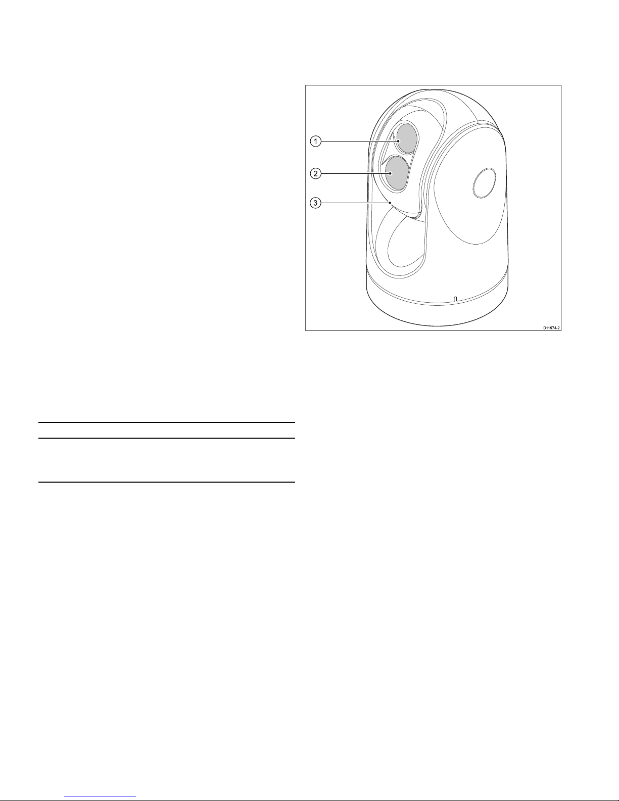
2.2T-Seriesthermalimagingcameras
T-Seriesisamaritimethermalimagingsystemforuseonnearlyany
kindofvessel.Itprovidesaclearimageinlow-lightandno-light
conditions.Forexample,athermalcameracanhelpyounavigate
atnightoridentifyobstaclesinareasoflowvisibilityoreventotal
darkness.
D11974 -2
1
2
3
1.Thermalcameralenswindow
2.Visiblelightcameralenswindow
3.Gimbalassembly
TheT-Seriessystemhasthefollowingkeyfunctionsandfeatures:
•Pan,tiltandzoomoperations.
•Automaticcameraadjustmenttosuitchangingconditions.
•Presetmodes(Scenes)optimizedforprevailingconditions.
•Automaticwindowheaterstode-icethelenswindowincold
weather.
•Singleanddualpayloadcongurations.(T400,T403,T450,
T453,T460andT463aredualpayloadmodelswithboththermal
andvisiblelight(greyscale)capabilitytoenhancelowlight
performance.)
•TheT470SCandT473SCmodelsincludesamechanical
stabilizationfeaturewhichimprovesimagestabilityby
compensatingforvesselmotionandboththermalandcontinuous
zoomcolorvisiblelightcamera.
10T-Series
Page 11

Chapter3:Planningtheinstallation
Chaptercontents
•3.1Thermalcamerasystemonpage12
•3.2Installationchecklistonpage13
•3.3Typicalsystemswiththermalcamerasonpage14
•3.4Thermalcamerapartssuppliedonpage16
•3.5JCU—Partssuppliedonpage16
•3.6T oolsrequiredonpage17
Planningtheinstallation
11
Page 12
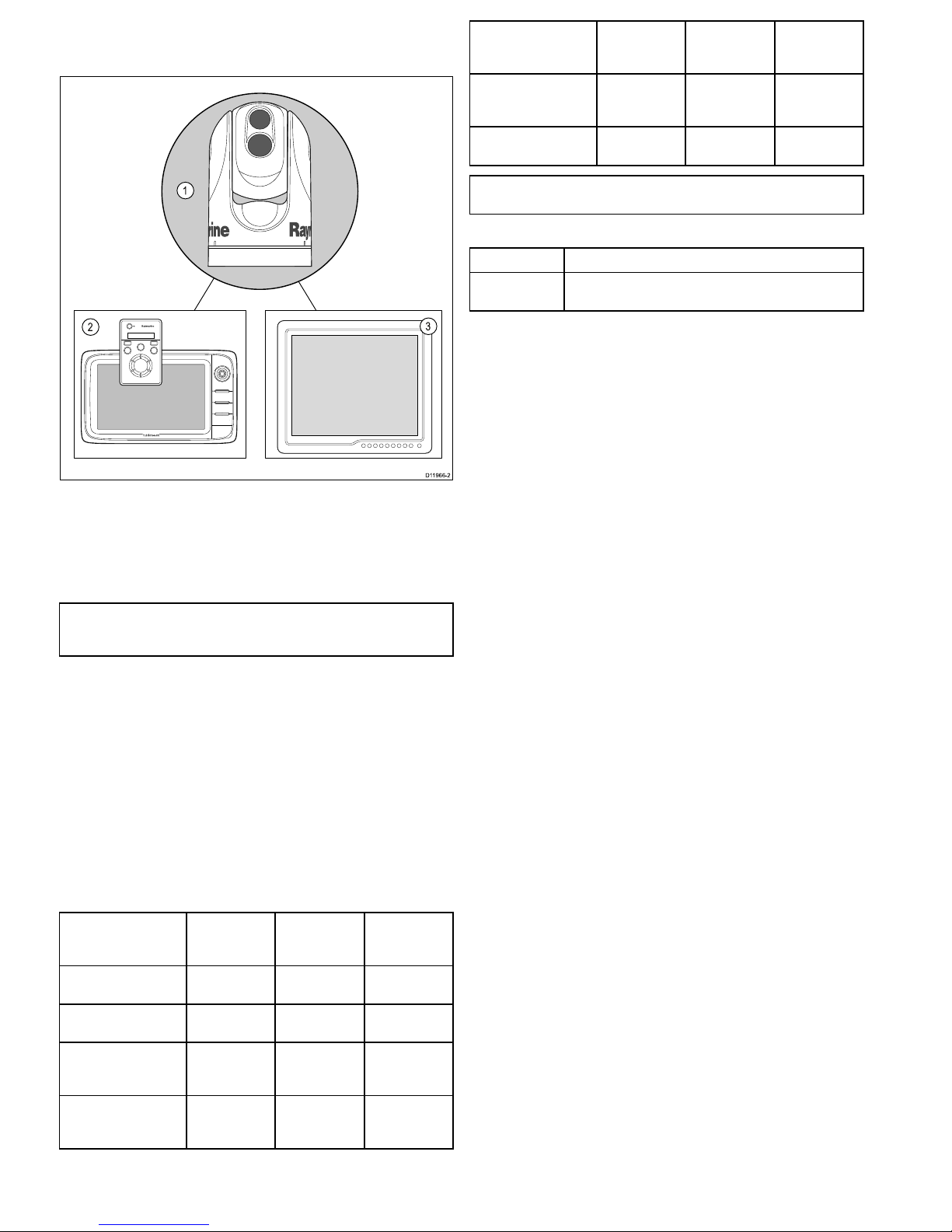
3.1Thermalcamerasystem
Atypicalthermalcamerasystemcomprisestheitemsshownbelow:
D11966 -2
1
2
3
1.Thermalcamera
2.Controller–Thisprovidesthecontrolstooperateandcongure
thecamera.
3.Display–Thisdisplaysthethermalvideoimageaswell
asstatusinformationandon-screenmenusprovidedbythe
camera.
Note:Thecontrolleranddisplaymaybethesamedevice.Some
Raymarinemultifunctiondisplaysprovideathermalcamera
applicationwhichhasasetofintegralcameracontrols.
Additionalcontrollersandequipment
Youmayhaveadditionalequipmentaspartofyourthermalcamera
system:
•Multiplecontrollersanddisplays,forexampleacameraserving
multipledisplay/controlstations.
•SeaT alk
hs
networkswitch–Usedtocreateanetworkof
compatibleRaymarineequipment.
•GVMvideomodule–Usedtodistributethevideosignalarounda
RaymarineG-Seriessystem.
Compatibledisplaysandcontrollers
ThefollowingRaymarinedisplaysandsystemsarecompatiblewith
theT-Seriesrangeofthermalcameras.
Multifunctiondisplay
systemDirectvideoNetworkvideo
Integrated
camera
controls
c-series—c95,c97,
c125,c127
●●
e-series—e7,e7D,
e95,e97,e125,e127
●●
G-Seriessystem●(direct
toG-Series
monitor)
●(using
GVM400video
module)
●
E-SeriesWidescreen
—E90W,E120W,
E140W
●●
Multifunctiondisplay
systemDirectvideoNetworkvideo
Integrated
camera
controls
C-SeriesWidescreen
—C90W,C120W,
C140W
●
E-SeriesClassic—
E80,E120
●
Note:Displayswithoutintegratedcameracontrolsrequirea
separateJCU(JoystickControlUnit).
Dedicatedcameracontrollers
ControllerDescription
Joystickcontrol
unit(JCU)
Dedicatedthermalcameracontroller,featuring3axispuck
control,functionkeysandanLCDdisplay.
12
T-Series
Page 13

3.2Installationchecklist
Installationincludesthefollowingactivities:
InstallationTask
1Planyoursystem.
2
Obtainallrequiredequipmentandtools.
3
Siteallequipment.
4Routeallcables.
5
Drillcableandmountingholes.
6Makeallconnectionsintoequipment.
7
Secureallequipmentinplace.
8Poweronandtestthesystem.
Schematicdiagram
Aschematicdiagramisanessentialpartofplanninganyinstallation.
Itisalsousefulforanyfutureadditionsormaintenanceofthe
system.Thediagramshouldinclude:
•Locationofallcomponents.
•Connectors,cabletypes,routesandlengths.
Planningtheinstallation
13
Page 14
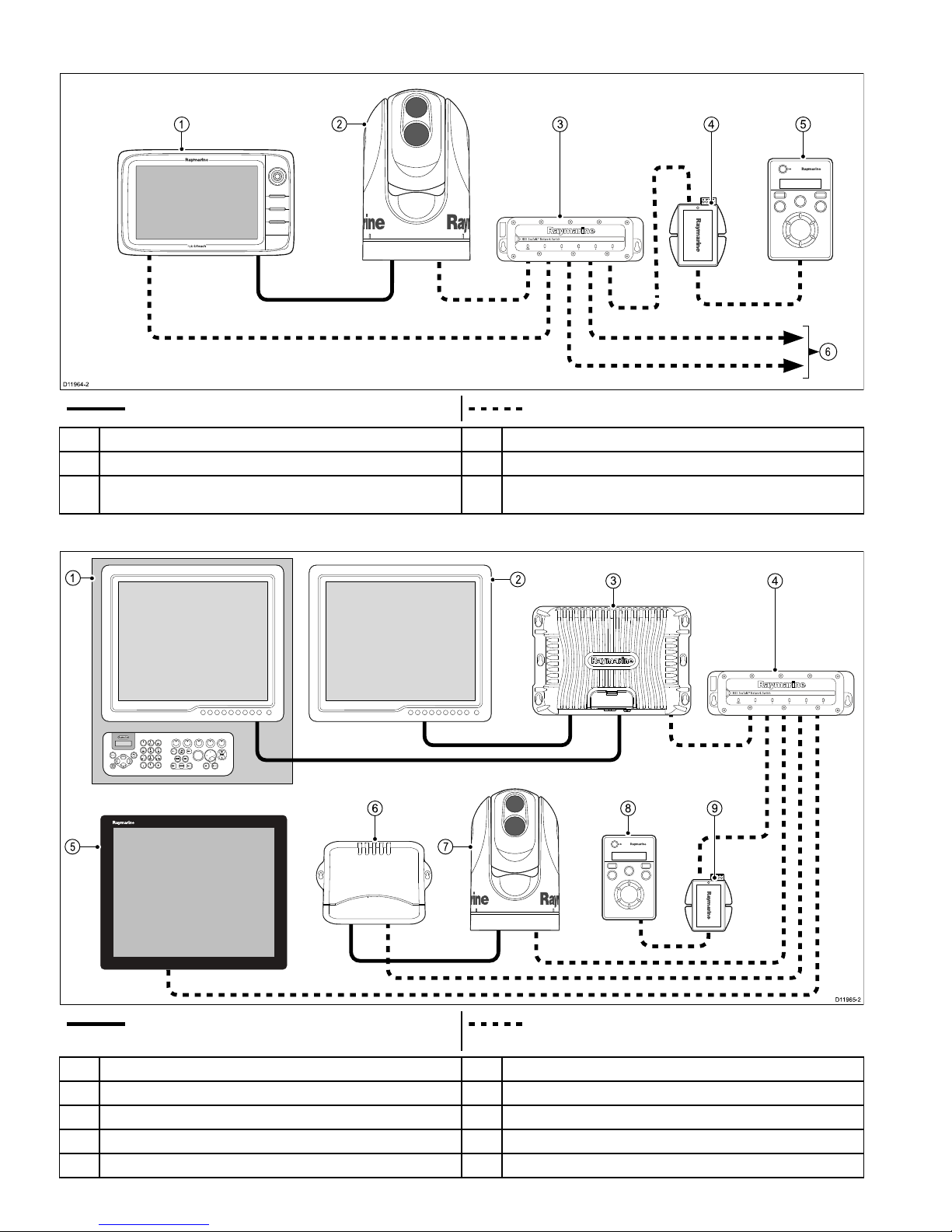
3.3Typicalsystemswiththermalcameras
Examplesystemwithfullyintegrateddisplay
6
D11964 -2
1
3
4 5
2
Videocable–Carriesthethermal/visiblelightvideoimage.SeaTalk
hs
–Includesthecameracontrolcommunications.
1
e/c-seriesdisplay
4
PoEinjector(RequiredifJCUisincludedinthesystem.)
2Thermalcamera
5
JCU(optional)
3Raymarinenetworkswitch6
SeaTalk
hs
tootherdigitaldevices:Additionaldisplays/controllers,Radar,
etc.
G-Seriessystem
9
9
W
W
X
X
Y
Y
Z
Z
8
8
T
T
U
U
V
V
7
7
P
P
Q
Q
R
R
S
S
4
4
G
G
H
H
I
I
5
5
J
J
K
K
L
L
6
6
M
M
N
N
O
O
A
A
C
C
T
T
I
I
V
V
E
E
W
W
P
P
T
T
S
S
M
M
O
O
B
B
D
D
A
A
T
T
A
A
M
M
E
E
N
N
U
U
P
P
A
A
G
G
E
E
.
.
0
0
2
2
A
A
B
B
C
C
3
3
D
D
E
E
F
F
1
1
C
C
A
A
N
N
C
C
E
E
L
L
S
S
T
T
A
A
N
N
D
D
B
B
Y
Y
D
D
O
O
D
D
G
G
E
E
P
P
I
I
L
L
O
O
T
T
O
O
K
K
R
R
A
A
N
N
G
G
E
E
O
O
U
U
T
T
I
I
N
N
E
E
N
N
T
T
E
E
R
R
D11965 -2
3
4
6 8 9
1
2
5 7
Videocable
SeaTalk
hs
–Includesthecameracontrolcommunications(andvideo
signalonG-Seriessystem).
1
G-SeriesNavstation
6
G-SeriesGVM400videomodule
2Repeatmonitor
7
Thermalcamera
3
G-SeriesGPM400
8
JCU(optional)
4Raymarinenetworkswitch9
PoEinjector(RequiredifJCUisincludedinthesystem.)
5
Glassbridgemonitor
14
T-Series
Page 15

Systemwithbasic/classicdisplay(s)
Thisarrangementisapplicablefordisplayswhichdonothavethethermalcameraapplicationandintegratedcameracontrols.
D119 78-2
1
3
2
Videocable–Carriesthethermal/visiblelightvideoimage.
Ethernet–Includesthecameracontrol
1Thermalcamera
2
JCU(required)
3
Monitor/Display
SeaTalk
hs
SeaTalk
hs
isanethernetbasedmarinenetwork.Thishighspeed
protocolallowscompatibleequipmenttocommunicaterapidlyand
sharelargeamountsofdata.
InformationsharedusingtheSeaT alk
hs
networkincludes:
•Sharedcartography(betweencompatibledisplays).
•Digitalradardata.
•Sonardata.
Planningtheinstallation
15
Page 16

3.4Thermalcamerapartssupplied
x6 x6 x6
x6
D119 68-2
2
5
6
1
3
4
1.T-Seriesthermalcamera
2.Mountingfasteners
3.Ethernetwaterproofcoupler
4.SmallO-ring
5.Documentationpack(containing:cameramountingtemplate,
warrantypolicyanddocumentationCD.)
6.LargeO-ring
Unpackthecameraunitcarefullytopreventdamage.Savethe
cartonandpackingincasetheunithastobereturnedforservice.
Additionalitemsrequired
Tocompletetheinstallationyouwillalsoneedtoobtainthefollowing
items:
•Compatibledisplay/controlhardware.
•Cablesforpower,ground,videoandnetworkconnection.
•Threadlockingcompound(forexampleLoctite242orequivalent),
requiredforallmetal-to-metalthreadedconnections.
Optionalaccessories
Youmayalsorequirethefollowingitems:
•T opDownInstallationKit(plateorriser).Requiredifthecamera
istobemountedonasurfacewithnoaccesstotheunderside(for
exampleontopofasealedenclosure).
3.5JCU—Partssupplied
T-SeriesthermalcameraswithJCUincludedaresuppliedwiththe
followingadditionalparts:
D11967 -2
1
3
2
4
5
78.74 ±1.25 mm (3.1 ±0.049 in) cutout
6.4 mm
(0.25 in)
diameter
72.4 mm (2.9 in) optional drill guide
90.4 mm (3.6 in) outside of JCU
129.54 ±1.25 mm (5.1 ±0.049 in) cutout
123.2 mm (4.9 in) optional drill guide
141.4 mm (5.6 in) outside of JCU
This document may not print true to scale. Before modifying mounting
surface, ensure printed template matches the measurements provided.
D11991-1
6
1.JoystickControlUnit(JCU).
2.Bezel.
3.Suncover.
4.Mountingtemplate
5.PoweroverEthernet(PoE)injector .
6.PoEcable7.62m(25').
Note:TheJCUpartnumberE32130canalsobeordered
separately.
16T-Series
Page 17

3.6Toolsrequired
Thefollowingtoolsarerequiredforinstallation.
D1233 3-1
1
2
3
4
5
6
ItemDescription
1.Drill
2.6mmspanner
3.6.4mmdrillbit
4.
Jigsaw(onlyrequiredforJCU
installation)
5.
Pozi-drivescrewdriver(onlyrequired
forJCUinstallation)
6.Thread-lock
Planningtheinstallation
17
Page 18

18T-Series
Page 19

Chapter4:Cablesandconnections
Chaptercontents
•4.1Generalcablingguidanceonpage20
•4.2Connectionoverviewonpage20
•4.3Powerconnectiononpage21
•4.4JCUConnectiononpage22
Cablesandconnections19
Page 20

4.1Generalcablingguidance
Cabletypesandlength
Itisimportanttousecablesoftheappropriatetypeandlength
•Unlessotherwisestateduseonlystandardcablesofthecorrect
type,suppliedbyRaymarine.
•Ensurethatanynon-Raymarinecablesareofthecorrectquality
andgauge.Forexample,longerpowercablerunsmayrequire
largerwiregaugestominimizevoltagedropalongtherun.
Routingcables
Cablesmustberoutedcorrectly,tomaximizeperformanceand
prolongcablelife.
•DoNOTbendcablesexcessively.Whereverpossible,ensurea
minimumbenddiameterof200mm(8in)/minimumbendradius
of100mm(4in).
100 mm (4 in)
200 mm (8 in)
•Protectallcablesfromphysicaldamageandexposuretoheat.
Usetrunkingorconduitwherepossible.DoNOTruncables
throughbilgesordoorways,orclosetomovingorhotobjects.
•Securecablesinplaceusingtie-wrapsorlacingtwine.Coilany
extracableandtieitoutoftheway.
•Whereacablepassesthroughanexposedbulkheadordeckhead,
useasuitablewatertightfeed-through.
•DoNOTruncablesneartoenginesoruorescentlights.
Alwaysroutedatacablesasfarawayaspossiblefrom:
•otherequipmentandcables,
•highcurrentcarryingacanddcpowerlines,
•antennae.
Strainrelief
Ensureadequatestrainreliefisprovided.Protectconnectorsfrom
strainandensuretheywillnotpulloutunderextremeseaconditions.
Circuitisolation
Appropriatecircuitisolationisrequiredforinstallationsusingboth
ACandDCcurrent:
•Alwaysuseisolatingtransformersoraseparatepower-inverter
torunPC’s,processors,displaysandothersensitiveelectronic
instrumentsordevices.
•AlwaysuseanisolatingtransformerwithWeatherFAXaudio
cables.
•Alwaysuseanisolatedpowersupplywhenusinga3rdparty
audioamplier.
•AlwaysuseanRS232/NMEAconverterwithopticalisolationon
thesignallines.
•AlwaysmakesurethatPC’sorothersensitiveelectronicdevices
haveadedicatedpowercircuit.
Cableshielding
Ensurethatalldatacablesareproperlyshieldedthatthecable
shieldingisintact(e.g.hasn’tbeenscrapedoffbybeingsqueezed
throughatightarea).
4.2Connectionoverview
D11957 -1
2
1
4
3
5
1.Poweranddrain
2.IRout–Thermalcameravideo
3.SeaTalk
hs
–ToRaymarinenetworkswitchorJCU
4.VIS/IRout–Visiblelightandthermalvideo.(Dualpayload
only,VIS/IRareswitchedusingcameracontrols.)
5.Lowimpedancegroundconnection
Connectioncarepoints:
•Youmustprovidealowimpedancechassistogroundconnection,
thisismadetoanyoneofthechassisthreadedxingpointsand
isinadditiontothedrain-to-groundconnection.
•The450mm(18in)cabletailsshouldberoutedtoadryareaof
thevesselforconnection.Alternativelyyoumustensurethatall
connectionsaremadewatertight.
•EnsurethattheVIS/IRfeedisconnectedondualpayloadmodels.
Withoutthisconnectiontheuserwillnotbeabletousethe
cameracontrollerstoswitchbetweenthethermalandlowlight
(visible)cameraimages.
Thermalcameracables
Cablingrequirementsforthermalcameras.
Cameratonetworkswitch
Anetworkpatchcableisrequiredtoconnectthecameratothe
networkswitch.Theconnectionismadebetweenthecamera
cabletailandthenetworkswitchviathecoupler(suppliedwiththe
camera).Networkpatchcablesareavailableinavarietyoflengths.
JoystickControlUnit(JCU)
AnEthernet(withpower)cableisusedtoconnecttheJCU.TheJCU
issuppliedwitha7.62m(25ft)Ethernetcableforthisconnection.If
yourequireadifferentlengthcontactyourdealerforsuitablecables.
PoweroverEthernet(PoE)injectortonetworkswitch
AnetworkpatchcableisrequiredforconnectingthePoEinjector
tothenetworkswitch.Networkpatchcablesareavailableina
varietyoflengths.
Videocables
Videocablesarenotsuppliedwiththeproduct.Pleasecontactyour
dealerforsuitablecablesandadaptors.
RaymarinerecommendstheuseofaBNCterminatedRG5975ohm
(orbetter)coaxialcable.
20T-Series
Page 21

SeaTalk
hs
patchcables
CablePartnumber
1.5m(4.9ft)SeaT alk
hs
patchcable
E06054
5m(16.4ft)SeaT alk
hs
patchcable
E06055
10m(32.8ft)SeaT alk
hs
patchcable
E06056
15m(49.2ft)SeaT alk
hs
patchcable
A62136
20m(65.6ft)SeaT alk
hs
patchcable
E06057
4.3Powerconnection
Powermustbesuppliedtothecamerafromanappropriatepower
source.
Powerconnectionrequirements
•12or24Vdcnominalsupplyvoltage
•Isolatedpowersupply
•Connectedviaanappropriatelyratedthermalbreakerorfused
switch.
Powerconnectioncolors
ColorDescription
Red
Powerin+ve(12/24V)
Black
Powerin-ve(0V)
GreenDrain/Ground
Powercable
Thepowerconnectionismadetoa450mm(18in)tailoutofthe
camerabase.Extendthistailwithappropriatecableasperthetable
below.
Totallength(max)SupplyvoltageCablesize
12V
1.5mm
2
(16AWG)
0–8m(25ft)
24V
0.8mm
2
(18AWG)
12V
2.0mm
2
(14AWG) 8–16m(50ft)
24V
0.8mm
2
(18AWG)
12V
3.5mm
2
(12AWG) 16–24m(75ft)
24V
0.8mm
2
(18AWG)
12V
5.5mm
2
(10AWG) 24–32m(100ft)
24V
0.8mm
2
(18AWG)
Breakers,fusesandcircuitprotection
Raymarinerecommendsthatyoutathermalbreakerorfusefor
thecameraatthedistributionpanel.
CameraRecommendedfuse
Allmodels5Amp.
Sharingabreaker
Wheremorethan1pieceofequipmentsharesabreakeryoumust
provideprotectionfortheindividualcircuits.E.g.byconnectingan
in-linefuseforeachpowercircuit.
D11637-1
+VE bar
Circuit breaker
FuseFuse
-VE bar
Where possible, connect individual items of
equipment to individual circuit breakers.
Where this not possible, use individual in-line
fuses to provide the necessary protection.
Cablesandconnections
21
Page 22

Grounding—Dedicateddrainwire
Thepowercablesuppliedwiththisproductincludesadedicated
shield(drain)wireforconnectiontoavessel'sRFgroundpoint.
ItisimportantthataneffectiveRFgroundisconnectedtothe
system.Asinglegroundpointshouldbeusedforallequipment.
Theunitcanbegroundedbyconnectingtheshield(drain)wireof
thepowercabletothevessel'sRFgroundpoint.Onvesselswithout
anRFgroundsystemtheshield(drain)wireshouldbeconnected
directlytothenegativebatteryterminal.
Thedcpowersystemshouldbeeither:
•Negativegrounded,withthenegativebatteryterminalconnected
tothevessel'sground.
•Floating,withneitherbatteryterminalconnectedtothevessel's
ground
Warning:Positivegroundsystems
Donotconnectthisunittoasystemwhichhaspositive
grounding.
4.4JCUConnection
TheJCU(JoystickControlUnit)canbeconnectedaspartofthe
SeaTalk
hs
network.Alternativelyitcanbeconnecteddirectlytothe
thermalcameraprovidedthattherearenoothercameracontrollers
onthesystem.
ConnectiontotheSeaTalk
hs
network
TheJCUisconnectedtotheSeaT alk
hs
networkviathePoE(power
overEthernet)injectorsuppliedwiththeJCU.
D11980-2
1
5
3
4
6
2
1.Thermalcamera
2.Raymarinenetworkswitch
3.Ethernetcoupler
4.JCU
5.PoEinjector
6.SeaTalk
hs
tootherdevices(e.g.multifunctiondisplay,digital
radar...).
D11981-1
54 4
21
3
1.PoEinjector
2.PoEcable.
3.JCU
4.PowertoPoEinjector
5.SeaTalk
hs
connection(toSeaT alk
hs
switch)
Cables
SeaTalk
hs
connectionUseaSeaTalk
hs
patchcable.Theseare
availableinvariouslengthsfromyourdealer.
JCUtoPoEinjectorUsethe7.62m(25')PoEcablesuppliedwith
theJCUforthisconnection,ifyourequire
adifferentlengthcontactyourdealerfor
suitablecables.
Connectiondirecttocamera
DirectconnectionisonlyvalidiftheJCUistheonlycontrollerand
therearenodisplayswiththethermalcameraapplication.
22
T-Series
Page 23

D11979-1
1
2
3
1.Thermalcamera
2.JCU
3.Ethernetcoupler ,suppliedwithcamera
Cables
CameratoEthernetcouplerUsethe450mm(18”)tailhardwiredfrom
thecamera.Shouldyouneedtoextendthis
useaSeaT alk
hs
patchcableandadditional
coupleravailablefromyourdealer.
JCUtoEthernetcouplerUsethe7.62m(25')PoEcablesuppliedwith
theJCUforthisconnection,ifyourequire
adifferentlengthcontactyourdealerfor
suitablecables.
Cablesandconnections23
Page 24

24
T-Series
Page 25

Chapter5:Installation
Chaptercontents
•5.1Cameramountingonpage26
•5.2JCUMountingonpage27
Installation25
Page 26

5.1Cameramounting
Locationrequirement
Whenplanningtheinstallationlocation,considerthefollowing
points:
•Thecameraiswaterproof,andappropriateforabovedecks
mounting.
•Theunderside(inside)ofthecompartmentordeckontowhich
thecameraismountedmustbeweathertight.Youmustensure
protectionfromwateringresstocablesandconnections.
•Themountingsurfacemustbehorizontal.
•Ifyoucannotaccessbothsidesofthemountingsurface,thenyou
willneedtheoptional“topdownmountingkit”.
•Mountingscrewsaresuppliedforamountingsurfaceofupto
41mm(1.6in)thick.Athickersurfacewillrequiretheinstallerto
providealternativefasteners.
•Thecameramountingsurfacemustbeatleastaslargeasthe
footprintofthecameraitselftoensureanadequatesealwiththe
O-ring.
•Thecamerashouldbemountedashighaspractical,butwithout
interferingwithanyradar,navigationalorcommunications
electronics.
•Choosealocationthatwillprovidethemostunobstructedviewin
alldirections.
•Choosealocationasclosetothevessel’scenterlineaspossible.
Thisprovidesasymmetricalviewwhenlookingforwardoraft.
•Selectalocationthatisatleast1m(3ft)fromdevicesthat
maycauseinterference,suchasmotors,generatorsandradio
transmitters/receivers.
Cameraorientation
Thecameracanbemountedin2orientationsinformallyknownas
“Ballup”and“Balldown”.
Note:ThestabilizedvariantsoftheT-Seriesthermalcameras
MUSTbemountedintheballupconguration.
D11975-1
Ballup:Thecameraismountedon
topofthemountingsurface.
D11976-1
Balldown:Thecameraissuspended
upsidedown,belowthemounting
surface.
Note:Forballdownmountingyoumustsettheballdownoption
inthecamerasystemsetupmenuappropriately .
Mountingthecamera
Usetheseinstructionstomountthecameraunitinposition.
D11971 -1
1.Usingthetemplatesupplied,markanddrilltheholesfor
mountingthecamera.
Mountingholescarepoints:
•Checkthedimensionsofanyprintedtemplate(toensurethat
thetemplateisprintedtothecorrectscale)priortodrillingany
holes.
•Notethecameraforwardmarkingsonthecamerabase,and
makesurethetemplateisorientedproperlyrelativetothebow
ofthevessel.Thisisaffectedbywhetherthecameraistobe
mountedball-uporball-down.
2.Installthe6xthreadedstudsintothebaseofthecamerawith
thread-lockingcompound.Ifrequired,youcanusestudsofa
differentlengthtosuityourinstallation.
Tightenthestudstoatorqueof9.5Nm(7lb-ft).
3.InstalltherubberO-ringinthebaseofthecamera.
4.Threadthepowersupply,video,andnetworkcablesfromthe
camerathroughthecenterhole,andthenplacethecameraon
themountingsurface(ortop-downriserifapplicable)sothe
threadedstudsextendthroughthedrilledholes.
5.Maketherequiredcableconnectionstothecameratails.
6.Securethecamerabodytothemountingsurfacewiththe
suppliednutsandwashers.
Domecappednutsareprovidedforaneatersolutionwherethe
mountingisexposedtoview.
Youmustensureawatertightseal.Y oumayuseamarine-grade
sealantasanalternativetothemountingO-ring.
Mountingthecamerawiththetop-downkit
Thetop-downmountingkitisusedwhenaccesstotheunderside
ofthemountingsurfaceisrestricted.Usetheinstructionsbelowto
mountthecameraunitusingatop-downmountingkit.
1.Usethetop-downriserasatemplatetomarkanddrilltheholes
formountingthecamera.
26T-Series
Page 27

2.Fastenthecameraunittotheriserusingthe6xthreadedbolts
andasuitablethread-lockingcompound.
D11970 -1
•Notethecameraforwardmarkingsonthecamerabase.
Youmustensurethatthecameraisfacingthecorrectway
dependinguponwhetherthecameraistobemountedball-up
orball-down.
•EnsuretherubberO-ringispositionedcorrectlyinthebase
ofthecamera.
3.Maketherequiredcableconnectionstothecameratails.
4.Fastenthecamera-riserassemblytothemountingsurfaceusing
thefastenerssupplied.
D11977 -1
Youmustensureawatertightseal.Y oumayuseamarine-grade
sealantasanalternativetothemountingO-ring.
5.2JCUMounting
Locationrequirements
Whenplanningtheinstallationlocation,considerthefollowing
points:
•Selectapositiononyourvesselthatisclosetothemonitorthat
displaystheT-Seriescameravideooutput.
•EnsuretheJCUismountedatleast55cm(21.7")awayfromany
equipmentttedwithamagneticcompass.
•TheJCUcanbemountedtoadashorothersurfaceinany
orientation.
•Considercablelengthsandcablerouting.
Flushmounting
ThestandardmethodformountingtheJCUisaushorpanel
mountingarrangement.
Beforemountingtheunit,ensurethatyouhave:
•Selectedasuitablelocation.Aclear,atareawithsuitable
clearancebehindthepanelisrequired.
•Identiedthecableconnectionrequiredandtheroutethatthe
cablewilltake.
•Detachedthefrontbezeltorevealthemountingscrews.
MountingtheJCU
1.Cutthemountingholeaccordingtothedimensionsspeciedin
themountingtemplateincludedinthisdocument.
2.Ensurethattheunittsintotheremovedareaandthenle
aroundthecutedgeuntilsmooth.
3.Drillfour6.4mm(0.25in)holesasindicatedonthetemplateto
acceptthemountingscrews.
4.BeforemountingtheJCU,insertthesuppliedethernetcable
throughthemountingholeandintotheJCUethernetport.
Ensurethecableglandsealingnutistightenedcorrectly.
5.Removethe4panelmountingclampsandinserttheJCUin
place.Afxthemountingclampstothescrewsontheotherside
ofthemountingsurface,ensuringthatthemountingclamps
arerotatedoutwardfromtheJCUhousing.Tightenthescrews
todrawthemountingclampsupagainstthemountingsurface
andthentightenanother1/4to1/2turn.Donotovertightenthe
screws.
i.Asshippedfromthefactory ,theJCUcanbemountedtoa
panelthicknessrangingfrom0.79to4.45cm(0.31to1.750
in).Theclampsaresetwiththesmall“foot”ontheclamp
facingtowardsthemountingsurface,awayfromthefrontof
theJCU,asshowninthe"Thickpanelmounting"diagram
inthisdocument.
ii.T omounttheJCUtoapanelthicknessof0.79cm(0.31in)or
less,removetheclampsfromthemountingscrews,turnthem
aroundandthreadthembackontoeachofthefourscrews.
Inthisconguration,theclamp“foot”facesawayfromthe
mountingsurfaceandallowstheclamptocontactthinner
panelsurfaceswhilestillallowingforpropercompression
oftheJCUmountinggaskettoformawatertightseal.This
mountingcongurationisshowninthe"Thinpanelmounting"
diagraminthisdocument.
6.OnceyouhavesecuredtheJCUinplace,replacethebezel.
Installation
27
Page 28

Thinpanelmounting
D11989 -1
Thickpanelmounting
D11990 -1
28T-Series
Page 29

Chapter6:Systemoperationandsetup
Chaptercontents
•6.1Thermalcameraimageonpage30
•6.2Operationandfeaturesoverviewonpage31
•6.3Powerupandstandbyonpage32
•6.4Cameracontrolonpage32
•6.5Imageadjustmentsonpage33
•6.6Systemresetonpage34
•6.7Setupmenusonpage35
Systemoperationandsetup
29
Page 30

6.1Thermalcameraimage
Thethermalcameraprovidesavideoimagewhichisshownon
yourdisplay .
Thevideofeedprovides:
•Thermalimage
•Statusicons/systeminformation(e.g.cameradirectionand
dockingmodeindicatorsintheexampleabove).
Youshouldtaketimetofamiliarizeyourselfwiththethermalimage.
Thiswillhelpyoutomakethemostofyoursystem:
•Considereveryobjectyouviewintermsofhowitwilllook
“thermally”asopposedtohowitlookstoyoureye.Forexample
lookforchangescausedbytheheatingeffectofthesun.These
areparticularlyevidentrightaftersunset.
•Experimentwithwhite-hotandblack-hot(reversevideo)modes.
•Experimentbylookingforhotobjects(suchaspeople)compared
tothecoldersurroundings.
•Experimentwiththecamerafordaytimeviewing.Thecamera
canprovideimproveddaytimeviewinginenvironmentswhere
traditionalvideocameraperformancesuffers,suchasinshadows
orbacklitscenes.
Thermalcamerastatusicons
Thethermalcameraimageincludesiconstoshowthecurrentstatus
ofthecamera.
IconDescription
Cameradirectionindicator.
Camerahomeposition.
Camerapaused.
Scenepresetmodefornightconditions.
Scenepresetmodefordaytimeconditions.
Scenepresetmodefornightdocking.
Scenepresetmodeforidentifyingpeopleorobjects
inthewater.
IconDescription
Rear-viewmode—imageisippedhorizontally.
Zoomsetting:2xzoom.
Zoomsetting:4xzoom.
Singleactivecontrolleronnetwork.
Multipleactivecontrollersonnetwork.
PC/laptopdetectedonnetwork.
Pointmodeenabled.
Pointmodedisabled.
StabilizationOff.
StabilizationOn.
FFC(FlatFieldCorrection)
PeriodicallythecamerawillperformaFlatFieldCorrection(FFC).
Thiswillnetunethethermalimagetosuitthecurrentambient
temperature.
TheFFCoperationisindicatedbyamomentarypauseandagreen
rectangledisplayedintheupperleftofthethermalvideoimage.
30T-Series
Page 31

6.2Operationandfeaturesoverview
Thecamerafeaturescanbeaccessedusingthethermalcamera
applicationofacompatibleRaymarinemultifunctiondisplay ,orfrom
adedicatedJCU(Joystickcontrolunit).
ThishandbookcoversmethodsusingtheJCU,fordetailsonhow
tooperatethisproductusingacompatibleRaymarinemultifunction
displaypleaserefertothethermalcameraapplicationsectionofthe
manualsuppliedwithyourmultifunctiondisplay.
ThemainThermalcameraoperationsareoutlinedbelow:
Controlthecamera:
•Switchthecamerabetweenoperationalandstandbymodes.
•Panandtilt
•Zoom
•Homeposition
•Pausethecameraimage
•Switchbetweenvisiblelightandthermalcameralenses.(Dual
payloadonly)
•Surveillancemode
Adjustthecameraimage:
•Colorpalette
•Scenepresets
•Reversevideo(whitehot/blackhot)
Inadditiontotheabove,thecameraalsoprovidessetupmenusto
congurethesystemtoyourrequirements.
JCUcontrolsoverview
D11956 -1
1
3
4
6
5
7
8
2
1
STANDBY/DIM
•Pressandhold–“Wake”thecamerafromstandbymodeor
accessthepowermenu.
•Momentarypress–ChangeJCUdisplaybrightness(3different
levels).
2
COLOR
Thefactorydefaultisforaredcolorimagetosuitenightnavigation.
Youmaychangethisusingthesetupmenus.
•Momentarypress–Cyclethroughtheavailablecolorsettings.
(Greyscale,Red,Sepia,RainbowandFusion.)
•Pressandhold–PerformFFC(FlatFieldCorrection)operation.
Thisperformsacorrectionforthecurrentambienttemperature.
3MENU–Accessthecamerasetupmenus.
•Pressonce–displayon–screensetupmenu.
•Pressagain–exitsetupmenu.
4
SCENE
•Shortpress–Selectbetweentheavailablescenepresets.
•Longpress(dualpayloadonly)–switchbetweenthethermal
andvisible-lightimage.
5
Display–ProvidesinformationregardingtheJCUandcamera
status.
6
USER–Aprogrammablebuttonforaccessingafavoritesettingor
functionnotprovidedontheotherkeys.Thedefaultoperationisthe
ReverseVideofunction(white-hot/black-hot).
•Shortpress–Performtheprogrammedaction.
•Pressandhold–ProgramtheUSERbuttonwithanotherfunction.
TheUSERbuttoncanbeprogrammedforthefollowingfunctions:
•SearchSettings
•SwitchThermal/VISVideo
•Hide/ShowAllIcons
•ReverseVideo
•RearviewMode
•SurveillanceMode
•PointMode
7
HOME
•Momentarypress–Returncameratohomeposition.
•Pressandhold–Setcurrentpositionascamerahome.
•4xpress–Resetthecamera(realignhomeandstowpositions).
8
PUCK–Usethepucktocontrolthecameraandnavigatethesetup
menus.
Controlcamera:
•Moveup,downleftright–Pan/Tiltcamera.
•Pressdown(andhold)–Zoomthermalimagein.
•Liftup–Zoomthermalimageout.
•Double-click(2quickpresses)–Pausethermalimage.(Move
puckinanydirectiontounfreeze.)
Navigatesetupmenus:
•Moveup,down–Scrollthroughmenuoptions.
•Pressdown–Selecthighlightedmenuoption.
Systemoperationandsetup
31
Page 32

6.3Powerupandstandby
Whenthebreakerconnectingpowertothecameraisswitchedon,
thecamerawillrunabootupsequencelastingforabout1minute,
afterwhichthecamerawillbeinStandbymode.
Inorderforthecameratooperate,youmustbringthecameraout
ofstandbymodeusingthecameracontrols.
Thermalcamerastandby
Standbymodecanbeusedtotemporarilysuspendthethermal
camera'sfunctionswhenthecameraisnotneededforaprolonged
period.
Wheninstandbymodethecamera:
•DoesNOTprovidealivevideoimage.
•Movesthecameraintoits“stowed”(parked)position(lensfacing
downintothecamerabase)toprotectthecameraoptics.
•Engagesitspan/tiltmotorstoholdthecamerainplaceinrough
seas.
Note:The“stowed”(parked)positioncanbeconguredusingthe
camera'ssetupmenu.
Powermenu
Menuitem/DescriptionSettings/Operation
AssignJCUAssignstheJCUtothecamera.
JCUStndby?ThisoptionplacestheJCUinstandby.Thecamera
andothercontrollersonthesystemareunaffected.
CameraStndby?
Withthisoptionthecameramovestoitsstow
positionandentersstandbymode.TheJCU
remainsonandavailableto“wake”thecamera.
SystemOffThisoptionplacesboththeJCUandcamerainto
Standbymode.
CalibrateJCUUsethe“CalibrateJCU”functiontocalibratethe
JCUpuck.
Followtheonscreeninstructionstocalibratethe
puck:
•RotateCCW/CW–requiresyoutorotatethe
puckfullyclockwise,thencounter-clockwise.
thenpressthepucktocontinue.
Cancel
ExitthePowerMenu.
Accessingthepowermenu
Thepowermenucanbeaccessedbyfollowingthestepsbelow.
UsingtheJCU
1.PressandholdthePowerbuttonontheJCU.
TheJCULCDwillcountdownfrom3to0,afterwhichthepower
menuisdisplayed.
2.UsetheJCUPucktoselecttherelevantpoweroption.
3.SelectCanceltocancelthepowermenu.
Note:ThepowermenuisonlydisplayedontheJCU'sLCD
display.
6.4Cameracontrol
Pan,tiltandzoom
Thecameracontrolsallowforpanandtilt(elevation)ofthecamera,
aswellaszoom(magnication)ofthethermalimage.
D11973 -1
•Pancontinuouslythrough360º.
•Tilt(elevate)to±90ºrelativetothehorizon.
•Zoom(magnify)thethermalcameraimage.
Note:StabilizedvariantsoftheT-Seriesthermalcamerasinclude
acontinuouszoomfunction,non-stabilizedvariantscanswitch
betweenx2andx4magnication.
ZoomingthecamerausingtheJCU
TheJCUpuckisusedtocontrolthezoomfunctionofthethermal
camera,aniconwillbedisplayedon-screentoindicatethecurrent
zoomlevel.
Withnozoomlevelselected:
1.PushthePuckinandholdfor1secondtoturnon2Xzoom.
2.PushthePuckinandholdfor2secondstoturnon4Xzoom.
3.PullthePuckouttoreturntothepreviouszoomlevel.
Continuouszoom
TheT470SCandT473SChaveacontinuouszoomcolorvisible
lightcamera.Thevisiblelightcamerawillzoomtothesame
magnicationasthethermalcamera.However,whenthevisible
lightcolorcameraisviewedthezoomcancontinuetoapresetlimit.
Thermalcamerahomeposition
Thehomepositionisapresetpositionforthecamera.
Thehomepositionusuallydenesausefulreferencepoint—for
example,straightaheadandlevelwiththehorizon.Youcansetthe
homepositionasrequiredandtoreturnthecameratothehome
positionatanytime.
Thehomeiconappearson-screenmomentarilywhenthe
camerareturnstothehomeposition.Theiconasheswhena
newhomepositionisset.
32T-Series
Page 33

Thermalcamerasurveillancemode
Insurveillancemodethecamerapansleftandrightcontinuously.
Thecameracontinuestopanuntilsurveillancemodeisdisabled,or
theJCU(JoystickControlUnit)isusedtomovethecamera.When
thisoccursthecameradoesnotautomaticallyresumesurveillance
modeandthemodemustbeenabledagainifrequired.
ToenablesurveillancemodeusingonlytheJCUyoumustsetthe
UserprogrammablebuttontoSurveillancemode.
Thermalcamerastabilization
TheRaymarineT470SCandT473SCthermalcamerasincludesa
mechanicalstabilizationfeature.
Themechanicalstabilizationfeatureimprovesimagestabilityby
compensatingforvesselmotionandkeepingthecameraaimed
atthepointofinterest.Mechanicalstabilizationhastwoaspects:
horizontal(azimuth)andvertical(elevation).Bydefault,mechanical
stabilizationissettoon,whichprovidesthebeston-the-water
performanceparticularlywhenthevesselisunderwayandtraveling
onroughwaterorinswellconditions.Y oucandisableorenable
stabilizationwheneveryouwant.Whenyouenablefullstabilization
(horizontalandvertical),theStabilizationOn(nowave)iconashes.
Itdoesnotdisplaycontinually,sincethisisthenormalmodeof
operation.Ifyoudisablestabilization,theStabilizationOff(wave)
iconremainsonthescreentomakeyouawarethatthemotionof
thevesselcanaffectthecameraperformance.Thisisnotanormal
modeofoperation.Stabilizationisautomaticallyturnedoffwhen
thecameraisstowed,butthesystemrestoresyoursettingwhen
thecameraispoweredon.Youcanturnoffthehorizontal(pan)
stabilizationwhileretainingthetiltstabilizationbyenablingpoint
mode.
Enabling/Disablingstabilization
Stabilizationisenabledbydefault.Y oucanenableordisable
stabilizationatanytimebyfollowingthestepsbelow.
UsingtheJCU:
1.PressMENU.
2.SelectSystemSetup.
3.SelectEnableStabilizationtoturnonmechanicalstabilization,
or
4.SelectDisableStabilizationtoturnoffmechanicalstabilization.
5.PressMENUtocanceltheon-screenmenu.
Thermalcamerapointmode
Pointmodeisonlyapplicabletothermalcameraswhichhave
mechanicalstabilization.
Enablingpointmodeonlyhassignicancewhenstabilization
isenabled.Enablingpointmodeturnsoffthehorizontal(pan)
stabilizationwhileretainingthevertical(tilt)stabilization.Thiscan
behelpfulwhenyouwanttousethethermalcameraasanaide
tonavigationandkeepthecamerapointinginthesameposition
relativetothevesselasitturns.Forexample,youmayhave
stabilizationenabledandhavesetthecameratopointstraight
aheadrelativetothefrontofthevessel.Ifthevesselisturned
atasharpangleundertheseconditions,thecamerasensorwill
notfollowthedirectionofthevessel.Enablingpointmodekeeps
thecamerainsyncwiththevesseldirectionwhilemaintaininga
stableelevationposition.Whenpointmodeisenabled,alockicon
displays.Thecamera’sazimuthpositionisnowlockedtothebase.
Whenyoudisablepointmode,theunlockicondisplaysmomentarily.
Thecameraalwaysstartsupwithpointmodedisabled.
Enabling/Disablingpointmode
Pointmodeisdisabledbydefault.WithStabilizationenabledyou
canalsoenablepointmodeatanytimebyfollowingthestepsbelow .
UsingtheJCU:
1.PressMENU.
2.SelectEnablePointModetoturnonpointmode,orifalready
enabled
3.SelectDisablePointModetoturnoffpointmode.
4.PressMENUtocanceltheon-screenmenu.
6.5Imageadjustments
Thermalcamerascenepresets
Scenepresetsenableyoutoquicklyselectthebestimagesetting
forthecurrentenvironmentalconditions.
Duringnormaloperationthethermalcameraautomaticallyadjusts
itselftoprovideahigh-contrastimageoptimizedformostconditions.
TheScenepresetsprovide4additionalsettingsthatmayprovide
betterimageryincertainconditions.The4modesare:
NightRunning—scenepresetmodefornightconditions.
DayRunning—scenepresetmodefordaytime
conditions.
NightDocking—scenepresetmodefornightdocking.
Search—scenepresetmodeforidentifyingpeopleor
objectsinthewater.
Althoughthepresetnamesindicatetheirintendeduse,varying
environmentalconditionsmightmakeanothersettingmore
preferable.Forexample,thenightrunningscenepresetmightalso
beusefulwhileinaharbor.Youmaynditbenecialtoexperiment
withthedifferentscenepresetstodiscoverthebestpresettouse
fordifferentconditions.
Thermalcameracolormodes
Arangeofcolormodesareavailabletohelpyoudistinguishobjects
on-screenindifferentconditions.
Changingthecolormodeswitchesthethermalcameraimage
betweenagreyscalemodeand1ormorecolormodes.Thereare
5colormodesavailable.
Thefactorydefaultcolormodeisred,whichmayimproveyournight
vision.Thisdefaultmodecanbechangedifrequiredusingthe
camera'son-screenVideoSetupmenu.
Note:IfyouhavetheDisableColorThermalVideooption
selectedinthecamera'son-screenVideoSetupmenu,only2
colormodesareavailable—greyscaleandred.
Thermalcamerareversevideo
Youcanreversethepolarityofthevideoimagetochangethe
appearanceofobjectson-screen.
Thereversevideooption(videopolarity)switchesthethermal
imagefromwhite-hot(orred-hotifthecolormodesettingisactive)
toblack-hot.Thedifferencebetweenwhite-hotandblack-hotis
shownbelow:
White-hotthermalimage.
Black-hotthermalimage.
Systemoperationandsetup
33
Page 34

Youmaynditusefultoexperimentwiththisoptiontondthebest
settingtosuityourneeds.
Reversingthevideopolarity
Toreversethepolarityofthevideoimagefollowthestepsbelow.
UsingtheJCU:
1.PressMENU.
2.SelectVideoSetup.
3.SelectSetReverseVideo
4.SelectMENUtocanceltheon-screenmenu.
Thermalandvisible-lightoperation
“Dualpayload”thermalcamerasareequippedwith2cameras—a
thermalimaging(infrared)cameraandavisible-lightcamera.
Thermalcamera—provides
night-timeimagery,based
ontemperaturedifferences
betweenobjects.Thermal
imagingproducesaclear
imageevenintotaldarkness.
Visible-lightcamera—
providesblackandwhite(or
greyscale)imageryduringthe
dayandinlow-lightconditions.
Helpstoimprovenavigational
abilitiesinlow-lightconditions;
forexampleduringtwilight
hourswhenoperatingalong
intercoastalwaterwaysand
nearharborentrances.
Note:TheT470SCand
T473SChaveacolor
cameraandcontinuous
zoomlens.
Thermalcamerarearviewmode
Therearviewmodeipsthevideoimagehorizontally,providinga
“mirrorimage”.
Thisisusefulforexampleininstanceswherethecamerais
rear-facingandyouareviewingtheimageonaforward-facing
monitor.
Switchingthecameratorearviewmode
Toswitchthecameratorearviewmodefollowthestepsbelow.
UsingtheJCU
1.PressMENU.
2.SelectSystemSetup.
3.SelectEnableRearviewMode.
WhenenabledtheoptionischangedtoDisableRearview
Mode,selectingthiswillrevertbacktonormalview.
4.PressMENUtocanceltheon-screenmenu.
6.6Systemreset
ResettingtheJCU
OccasionallyitmaybenecessarytoresettheJCU,todothisyou
caneitherpowercycletheJCUorfollowthestepsbelow:
1.PressandholdtheSCENE,COLORandHOMEbuttonsfor
1second.
Resettingthethermalcamera
Usethisproceduretoresetthethermalcamera.Thiswillrealignthe
homeandstowpositions,forexampleiftheybecomemisaligned
duetoheavyweather .
1.PresstheHOMEbutton4timessuccessivelytoresetthe
camera.
Restoringfactorydefaults
Usethisproceduretoresetthecameratoitsfactorydefaultsettings.
Withthecamerasetupmenudisplayed:
1.SelecttheAbout/Helpmenu.
2.SelectRestoreFactoryDefaultsfromtheavailableoptions.
34T-Series
Page 35

6.7Setupmenus
Thesetupmenusprovidearangeoftoolsandsettingstocongure
thethermalcamera.
Themenuscanbeaccessedfromanycontrolleronthesystem.The
menusareoverlaidontothevideoimage.
Note:Theon-screenmenusonlyappearonthethermalcamera
image.Theyarenotavailablewhenviewingthevisiblelight
image(ondualpayloadmodels).
Menusavailable
EnablePointMode/
DisablePointMode
SelectingEnablePointmodewillturnpointmodeon,
selectingdisablepointmodewillturnpointmodeoff.
Onlyappliestomodelswithmechanicalstabilization.
VideoSetupThismenuisusedtosetthevideoconguration
options.
SetSymbologySettingsassociatedwiththestatusicons.
UserProgrammable
Button
ConguretheUSERbuttonontheJCU.
SystemSetupSettingstooptimizeoperationforthisparticularsystem
/installation.
About/HelpHelpfulinformationandrestoretofactorydefaults
setting.
Exit
Cancelson-screenmenu.
Videosetupmenu
Menuitem/DescriptionSettings/Operation
SetThermalColor
Default
Thissavesthecurrentcolorsettingasthedefault
value.
SetReverseVideo
Default
Thistogglestheinfraredimagebetweenwhite-hot
(orred-hotifviewingacolorimage)andblack-hot.
Enable/DisableColor
ThermalVideo
Enableordisablethethermalcolorpalettes:
•Enabled–Greyscale,Red,Sepia,Rainbowand
Fusionpalettesareavailable.
•Disabled–OnlyGreyscaleandRedpalettes
areavailable.
DisplayTestPatternUsethedisplaytestpatternwhensettingupthe
color/contrastsettingsforyourparticulardisplay
ormonitor.Youcanswitchthroughthe4test
patternsavailable.
Exit
Setsymbologymenu
Menuitem/DescriptionSettings/Operation
Enable/DisablePCIcon•Enabled–ThePCiconisdisplayedwhenevera
PCisdetectedonthenetwork.
•Disabled–ThePCiconisnotdisplayed.
Enable/DisableJCU
Icon
•Enabled–TheJCUiconisdisplayedwhenever
aJCUisdetectedonthenetwork.
•Disabled–TheJCUiconisnotdisplayed.
DisplayAllIcons
Selectingthismenuitemenablesallavailable
icons.
DisplayMinimalIcons
Selectingthismenuitemreducestheiconactivity:
•Position,Zoom,Rearview,Pause,Stabilization
disabledandPointModeenablediconsare
unaffected.
•HomeandSceneiconsaredisplayedonly
momentarily.
•Othericonsarenotshown.
Menuitem/DescriptionSettings/Operation
HideAllIcons
Selectingthisoptionhidesalliconsexceptfor:
•Positionindicator
•Rearviewmodeenabled
•Stabilizationdisabled
•Pointmodeenabled
ExitReturnstothemainmenu.
UserProgrammableButtonmenu
UsethismenutosetuptheUSERbuttonontheJCU.
Menuitem/DescriptionUSERbuttonoperation
SearchsettingsTheUSERbuttonwillsetthecamerasceneto
Searchmode.
SwitchThermal/VIS
Video
(Dualpayloadmodels
only)
TheUSERbuttonwillswitchbetweenThermaland
LowLightcameraimages.
Hide/ShowAllIconsTheUSERbuttonwilltogglebetweenShowand
Hideiconsettings.
ReverseVideo
TheUSERbuttonwilltogglebetweentheWhite-hot
andBlack-hot(reverse)thermalimage.
RearviewMode
TheUSERbuttonwilltoggleRearviewmodeon
andoff.
SurveillanceModeTheUSERbuttonwilltoggleSurveillancemode
onandoff.
PointMode
TheUSERbuttonwilltogglePointModeonandoff.
ExitReturnstothemainmenu.
SystemSetupmenu
Menuitem/DescriptionSettings/Operation
Enable/Disable
Ball-DownInstallation
Thismenuoptionshouldbeenabledwhenthe
cameraismountedupsidedowninthe“ball-down”
conguration.
Enable/Disable
Twist-to-Panmode
ThismenuoptionchangestheJCUcontrolspan
andzoomfunctionsasfollows:
Enabled—PanthecamerabyrotatingthePuck
clockwiseorcounterclockwise,zoominandout
bypushingthepuckinandpullingitout.(Thisis
defaultoperationoftheJCU).
Disabled—PanthecamerabymovingthePuck
leftorright,zoominandoutbyrotatingthePuck
clockwiseandcounterclockwise.
Enable/DisableHigh
PowerStandby
Thisoptioncontrolstheamountofpowerusedto
holdthecamerainpositionwhileitisinStandby
mode.Theenabledsettingwillconsumemore
power,butwillhelpensurethatthecameraisheld
inplaceinroughseas.
Note:Ifthecameramoveswheninstandby
(duetoshockorvibration),thenthePosition
indicatororHomesettingmayneedrealigning
(resetthecameratorealign).
Systemoperationandsetup
35
Page 36

Menuitem/DescriptionSettings/Operation
Enable/DisableHigh
MotorTorque
Thisoptioncontrolstheamountofpowerusedto
holdthecamerasteadywheninuse.Theenabled
settingwillconsumemorepower,buthelpensure
thatthecameraisheldinplaceinroughseas.
TheHighMotorT orquemodemaybeusefulfor
powerboatsthatoperateathigherspeedsand
experiencehighimpactenvironments,andcan
accepthigherpowerconsumption.
Note:Ifthecameramovesduetoshockor
vibration,thenthePositionindicatororHome
settingmayneedrealigning(resetthecamera
torealign).
Enable/Disable
RearviewMode
Whenthisoptionisenabledthecameraimageis
reversedandyouwillseeamirrorimageonthe
display.
Enable/Disable
Stabilization
Whenthisoptionisenabledhorizontalandvertical
stabilizationisturnedon.OnlyappliestoT470SC
andT473SC.
SetStowPositionThisoptionsetsthecurrentpositionastheStow
position.Thecameramovestothestowposition
wheneveritisturnedofforputintoStandbymode.
NameCamera
Usethisoptiontonamethecamera.
Surveillancemode
Thisoptionsenablesyoutosetthescanwidthand
speedwheninsurveillancemode.
ExitExittomainmenu.
Highpower/Hightorquepoweruse
CameraStateCamerasettingDualpayload
Single
payload
Standby
•HighPowerMode
ON
•HighT orqueMode
ON
22W17.4W
Standby
•HighPowerMode
OFF
•HighT orqueMode
ON
8W7.4W
Standby
•HighPowerMode
ON
•HighT orqueMode
OFF
13W13W
Awake•HighPowerMode
OFF
•HighT orqueMode
OFF
8W7.4W
Awake•HighPowerMode
ONorOFF
•HighT orqueMode
ON
30W19.4W
Awake•HighPowerMode
ONorOFF
•HighT orqueMode
OFF
20W16.5W
Surveillancemodemenu
Menuitem/DescriptionSettings/Operation
ScanWidth
Thissettingdeterminesthedistancethatthe
camerapansleftandrightwheninsurveillance
mode.Selectfrom:
•Narrow—Thecamerawillscanapproximately
20ºleftandrightofthecenter(40ºtotal).
•Medium—Thecamerawillscanapproximately
40ºleftandrightofthecenter(80ºtotal).Or,
•WideThecamerawillscanapproximately80º
leftandrightofthecenter(160ºtotal).
ScanSpeed
Thisoptiondeterminesthespeedatwhichthe
camerapansleftandrightwheninsurveillance
mode.Selectbetween:
•Slow
•Medium
•Fast
Exit
About/Helpmenu
Menuitem/DescriptionSettings/Operation
VideoIconHelpScreensThisoptiondisplaysanexplanationofthepurpose
ofeachofthescreenicons.Usethedirection
controlstocyclethroughthepages.
ProductInformationThisoptiondisplaysinformationaboutthecamera:
•Name,
•Serialnumber ,
•MACaddress,and
•Softwareinformation.
ContactRaymarine
ThisoptiondisplaysRaymarinecontactdetails.
RestoreFactory
Defaults
Usethisoptiontorestorethecamerasettingsto
theirfactorydefaultvalue.
Exit
36T-Series
Page 37

Chapter7:Troubleshootingandsupport
Chaptercontents
•7.1Thermalcameratroubleshootingonpage38
•7.2Raymarinecustomersupportonpage39
Troubleshootingandsupport
37
Page 38

7.1Thermalcameratroubleshooting
Problemswiththethermalcameraandtheirpossiblecausesandsolutionsaredescribedhere.
ProblemPossiblecausesPossiblesolutions
CameraisinStandbymode.ThecamerawillnotdisplayvideoifitisinStandbymode.Usethecamera
controls(eitherthethermalcameraapplicationorJCU)to“wake”the
camerafromstandby.
Problemwiththethermalcameravideo
connections.
•Checkthermalcameravideocablesaresoundandproperlyconnected.
•Ensurethatthevideoisconnectedintovideoinput1atthemultifunction
displayorGVM.
•Ensurethatthecorrectvideoinputisselectedatthedisplay .
Videonotdisplayed.
Problemwithpowersupplytothecamera
orJCU(ifusedastheprimarycontroller)
•CheckthepowerconnectionstothecameraandJCU/PoEinjector(if
used).
•Ensurethatthepowerswitch/breakerison.
•Checkthefuse/breakerstate.
Cannotcontrolthermalcamerafrom
Raymarinedisplayorkeyboard.
Thermalcameraapplicationisnotrunning.
Ensurethethermalcameraapplicationisrunningonthemultifunction
display(asopposetothevideoapplicationwhichdoesnothavecamera
controls).
Checkthatthecontrollerandthermalcameraarecorrectlyconnectedto
thenetwork.(Note:ThismaybeadirectconnectionorviaaRaymarine
networkswitch.)
CheckthestatusoftheRaymarinenetworkswitch.
Networkproblem.
CheckthatSeaT alk
hs
/RayNetcablesarefreefromdamage.
Controlconict,e.g.causedbymultiple
usersatdifferentstations.
Ensurethatnoothercontrollersareinuseatthesametime.
Checkpower/networkcablingtothecontrollerandPoEinjector(PoEonly
usedwithoptionalJoystickControlUnit).
Erraticorunresponsivecontrols.
Problemwiththecontroller .
Checkothercontrollersifavailable.Ifothercontrollersareoperatingthiswill
eliminatethepossibilityofamorefundamentalcamerafault.
Cameraisnotadualpayloadmodel.Only“dualpayload”(duallens)thermalcamerassupportVIS/IRswitching. Cannotswitchbetweenthermaland
visible(VIS/IR)videoimage.
VIS/IRcablenotconnected.EnsurethattheVIS/IRcableisconnectedfromthecameratothe
Raymarinesystem.(TheIR-onlycabledoesnotsupportswitching).
Poorqualityorfaultyvideocable.
Ensurethatthevideocableisnolongerthannecessary.Thelongerthe
cableis(orthesmallerthewiregauge/thickness),themoreseverethe
lossesbecome.Useonlyhighqualityshieldedcablesuitableforamarine
environment.
Noisyimage.
Cableispickingupelectromagnetic
interference(EMI)fromanotherdevice.
•Ensureyouareusingahighqualityshieldedcable.
•Ensurepropercableseparation,forexampledonotrundataandpower
cablesincloseproximitywitheachother.
Displaybrightnessissettoolow .Usethebrightnesscontrolsatthedisplaytoadjustaccordingly.
Thecontrastorbrightnesssettingsinthe
thermalcameraapplicationaresettoo
low.
Usetheappropriatemenuinthethermalcameraapplicationtoadjustthe
contrastandbrightnessoftheimage.
Imagetoodarkortoolight.
TheSceneModeisnotappropriateforthe
currentconditions.
AparticularenvironmentmaybenetfromadifferentSceneModesetting.
Forexample,averycoldbackground(suchasthesky)couldcausethe
cameratouseawidertemperaturerangethanappropriate.UsetheSCENE
button.
Imagefreezesmomentarily.FFC(FlatFieldCorrection).
TheimagewillpausemomentarilyonaperiodicbasisduringtheFlatField
Correction(FFC)cycle.JustpriortotheFFC,asmallgreensquarewill
appearintheupperleftcornerofthescreen.
Imageisinverted(upsidedown).Camera“Balldown”settingisincorrect.
EnsurethattheBalldownsettingwithinthethermalcamerasystemsetup
menuissetcorrectly.
38T-Series
Page 39

7.2Raymarinecustomersupport
Raymarineprovidesacomprehensivecustomersupportservice.
YoucancontactcustomersupportthroughtheRaymarinewebsite,
telephoneandemail.Ifyouareunabletoresolveaproblem,please
useanyofthesefacilitiestoobtainadditionalhelp.
Websupport
Pleasevisitthecustomersupportareaofourwebsiteat:
www.raymarine.com
ThiscontainsFrequentlyAskedQuestions,servicinginformation,
e-mailaccesstotheRaymarineT echnicalSupportDepartmentand
detailsofworldwideRaymarineagents.
Telephoneandemailsupport
IntheUSA:
•Tel:+16033247900
•TollFree:+18005395539
•Email:support@raymarine.com
IntheUK,Europe,theMiddleEast,orFarEast:
•Tel:+44(0)1329246777
•Email:ukproduct.support@raymarine.com
Productinformation
Ifyouneedtorequestservice,pleasehavethefollowinginformation
tohand:
•Productname.
•Productidentity .
•Serialnumber .
•Softwareapplicationversion.
Youcanobtainthisproductinformationusingthemenuswithinyour
product.
Troubleshootingandsupport
39
Page 40

40T-Series
Page 41

Chapter8:Technicalspecication
Chaptercontents
•8.1T echnicalspecicationonpage42
Technicalspecication
41
Page 42

8.1Technicalspecication
Nominalsupplyvoltage12or24Vdc
Operatingvoltagerange-10%to+30%ofnominalsupplyrange
Current•Peak3.8A@12V
•Peak1.9A@24V
Powerconsumption25Wtypical,50WMax
EnvironmentalInstallationenvironment
•Operatingtemperature:-25ºCto
+55ºC(-13ºFto131ºF)
•Storagetemperature:-40ºCto
+85ºC(-40ºFto185ºF)
•Relativehumidity:max95%
•WaterprooftoIPX6
•Wind:100knot(1 15.2mph)
•Vibration:IEC60945;
MIL-STD-810E
•Sand/dust:MIL-STD-810E
•SaltMist:IEC60945
Electromagneticcompliance
EMI:IEC60945
Dimensions
•Basediameter:178mm(7in.)
•Height:279.4mm(1 1in.)
Note:T470SCandT473SC
heightis292mm(1 1.5in.)
Weight
<5.26kg(<11.6lb)–dependingon
thecameramodel
Pan/tilt•360°continuouspan
•+/-90°tilt
Videoout
NTSC
42
T-Series
Page 43

Page 44

www.raym a rin e.c om
 Loading...