

Page 1

RVM-400 SERIES
STAINLESS STEEL THRU-HULL REALVISION™ MAX 3D SONAR TRANSDUCERS
INSTALLATION
INSTRUCTIONS
English (en-US)
Document number:
© 2023 Raymarine UK Limited
06-2023Date:
87437 (Rev 2)
Page 2

Page 3

egalnotices
L
Trademarkandpatentsnotice
Raymarine,T acktick,ClearPulse,T ruzoom,Sea T alk,SeaTalk
FLIR,Y achtSense,DockSense,LightHouse,RangeFusion,Down Vision,SideVision,RealVision,HyperVision,Dragonfly,Element,Quantum,Axiom,
Instalert,InfraredEverywhere,TheWorld’sSixthSenseandClearCruiseareregisteredorclaimedtrademarksofFLIRSystems,Inc.
Allothertrademarks,tradenames,orcompanynamesreferencedhereinareusedforidentificationonlyandarethepropertyoftheirrespectiveowners.
Thisproductisprotectedbypatents,designpatents,patentspending,ordesignpatentspending.
hs
,Sea Talkng,andMicronet,areregisteredorclaimedtrademarksofRaymarineBelgium.
FairUseStatement
Y oumayprintnomorethanthreecopiesofthismanualforyourownuse.Y oumaynotmakeanyfurthercopiesordistributeorusethemanualinanyother
wayincludingwithoutlimitationexploitingthemanualcommerciallyorgivingorsellingcopiestothirdparties.
English(en-US)
Documentnumber:87437(R ev2)
AC;44930;2023-06-16T13:29:34
Page 4

Page 5

CONTENT
S
CHAPTER1IMPORTANTINFORMATION..............................7
Safetywarnings..........................................................................7
Productwarnings.......................................................................7
Regulatorynotices....................................................................8
DeclarationofConformity..............................................8
Disclaimer.............................................................................8
Warrantyregistration........................................................8
Productdisposal................................................................9
IMOandSOLAS.................................................................9
Technicalaccuracy...........................................................9
Publicationcopyright........................................................9
CHAPTER2DOCUMENTINFORMATION...........................10
2.1Applicableproducts...........................................................11
2.2Documentinformation.....................................................11
2.3Productdocumentation...................................................11
Documentillustrations....................................................11
Operationinstructions....................................................11
4.1Partssupplied—RVM-4xxseries
transducers.................................................................................17
Additionalpartssupplied...............................................17
CHAPTER5PRODUCTDIMENSIONS..................................19
5.1T ransducerdimensions—RVM-4xx..........................20
RealVisiontransducercableconnector
dimensions........................................................................20
CHAPTER6LOCATIONREQUIREMENTS..........................22
6.1Warningsandcautions....................................................23
6.2Locationrequirements....................................................23
Coredfiberglasshullmounting..................................24
6.3EMCinstallationguidelines..........................................25
CHAPTER7INSTALLATION...................................................26
7.1T oolsrequired.....................................................................27
7.2T estingthetransducer....................................................27
7.3T ransducermounting......................................................28
Drillingholesinthehull................................................28
CHAPTER3PRODUCTANDSYSTEMOVERVIEW...........12
3.1Productoverview................................................................13
RealVision™Max3Doverview.....................................14
Sonarrange........................................................................14
Compatiblesonarmodulesanddisplays................14
RealVisiontransducerextensioncables.................14
CHAPTER4PARTSSUPPLIED...............................................16
Assemblingtheexternalcomponents....................29
Assemblingtheinternalcomponents.....................30
Finalizingtheinstallation...............................................31
Anti-fouling.........................................................................32
CHAPTER8CABLESANDCONNECTIONS—
GENERALINFORMATION.......................................................33
8.1Generalcablingguidance...............................................34
5
Page 6

Cabletypesandlength.................................................34
13.1Physicalspecification......................................................51
trainrelief.........................................................................34
S
Cableshielding.................................................................34
CHAPTER9CONNECTIONS.................................................35
9.1Cablerouting.......................................................................36
9.2Attachingtheconnectorlockingcollar.....................36
9.3RVM-400connection.......................................................37
9.4RVM-412/RVM-420connection.................................37
9.5RealVisiontransducerextensioncables..................38
9.6Makingconnections.........................................................38
CHAPTER10SYSTEMCHECKSAND
TROUBLESHOOTING...............................................................39
10.1RealVision™AHRScalibration.....................................40
10.2Troubleshooting..............................................................40
Operationinstructions..................................................40
Sonartroubleshooting....................................................41
Resettingthesonarmodule........................................43
13.2Environmentalspecification.........................................51
13.3RealVision™Max3Dsonarspecification.................51
Sonarrange.......................................................................51
13.4Conformancespecification.........................................52
CHAPTER14SPARESANDACCESSORIES.......................53
14.1Spares...................................................................................54
14.2Accessories........................................................................54
CHAPTER11MAINTENANCE.................................................44
11.1Routinechecks...................................................................45
11.2Transducercleaning........................................................45
11.3Bridgingmaterialremoval.............................................45
11.4Re-applyinganti-foulingpaint......................................45
CHAPTER12TECHNICALSUPPORT...................................47
12.1Raymarineproductsupportandservicing..............48
12.2Learningresources.........................................................49
CHAPTER13TECHNICALSPECIFICATION.......................50
6
Page 7
CHAPTER1:IMPOR
Safetywarnings
TANTINFORMATION
W
arning:Productinstallationandoperation
•Thisproductmustbeinstalledandoperatedinaccordance
withtheinstructionsprovided.Failuretodosocouldresult
inpersonalinjury
productperformance.
•Raymarinehighlyrecommendscertifiedinstallationby
aRaymarineapprovedinstaller .Acertifiedinstallation
qualifiesforenhancedproductwarrantybenefits.
RegisteryourwarrantyontheRaymarinewebsite:
www.raymarine.com/warranty
,damagetoyourvesseland/orpoor
W
arning:Sonaroperation
•NEVERtouchthetransducerfacewhenthesonaris
poweredon.
•SWIT
CHOFFthesonarifdiversarelikelytobewithin7.6m
(25ft)ofthetransducer.
Productwarnings
Warning:Maximumtransducercablelength
ThemaximumlengthofcablebetweenaRealVision™Max
3DtransducerandaMFD/sonarmodule(includingthe
transducer’scaptivecable)mustNOTexceed18m(59ft).
Cablelengthsgreaterthanthismaycausedamagetothe
RealVision™Max3DtransducerandMFD/sonarmodule.
Warning:Highvoltage
Thisproductcontainshighvoltage.DoNOTremovecovers
orattempttoaccessinternalcomponents,unlessspecifically
instructedinthedocumentationprovided.
Warning:Switchoffpowersupply
Ensurethevessel’spowersupplyisswitchedOFFbefore
startingtoinstallthisproduct.DoNOTconnectordisconnect
equipmentwiththepowerswitchedon,unlessinstructedin
thisdocument.
Warning:Transducercables
Donotremovethetransducercablewhilsttheproductis
poweredon,doingsocancausesparks.Ifthetransducer
cableisaccidentlyremovedwhilsttheproductispoweredon,
switchtheproduct'spoweroff,replacethecableandthen
switchthepowerbackon.
Importantinformation
Warning:Positivegroundsystems
Donotconnectthisunittoasystemwhichhaspositive
grounding.
Warning:Transduceroperation
Onlytestandoperatethetransducerinthewater.DoNOT
operateoutofwaterasoverheatingmayoccur.
Caution:Donotcuttransducercables
•Cuttingthetransducercableseverelyreducessonar
performance.Ifthecableiscut,itmustbereplaced,it
cannotberepaired.
•Cuttingthetransducercablewillvoidthewarrantyand
invalidatetheEuropeanCEmark.
Caution:Serviceandmaintenance
Thisproductcontainsnouserserviceablecomponents.Please
referallmaintenanceandrepairtoauthorizedRaymarine
dealers.Unauthorizedrepairmayaffectyourwarranty.
7
Page 8
W
arning:Marine-gradesealant
Onlyusemarine-gradeneutralcurepolyurethanesealants.
DoNO
causedamagetoplasticparts.
W
Prolongede
anddieseloiletc.maycausethetransducertodiscolorand
degrade.
Tusesealantscontainingacetateorsilicone,whichcan
arning:Petrochemicals
xposuretopetrochemicalssuchasgasoline
Warning:Anti-fouling
•Failuretocomplywiththeprovidedanti-foulingand
transducercleaninginstructionsmayaffectyourproduct
warranty.
•Onlyusewater-basedanti-foulingpaint.
•DoNOTuseketoneorcopper-basedanti-foulingpaint.
TheoriginalDeclarationofConformitycertificatemaybeviewedonthe
relevantproductpageatwww.raymarine.com/manuals.
Disclaimer
Raymarinedoesnotwarrantthatthisproductiserror-freeorthatitis
compatiblewithproductsmanufacturedbyanypersonorentityotherthan
Raymarine.
Raymarineisnotresponsiblefordamagesorinjuriescausedbyyouruseor
inabilitytousetheproduct,bytheinteractionoftheproductwithproducts
manufacturedbyothers,orbyerrorsininformationutilizedbytheproduct
suppliedbythirdparties.
Third-partyhardware,suchasconverters,adapters,routers,switches,Access
Pointsetc.,providedbythirdparties,maybemadeavailabledirectlytoyou
byothercompaniesorindividualsunderseparatetermsandconditions,
includingseparatefeesandcharges.RaymarineUKLimitedoritsaffiliates
havenottestedorscreenedthethird-partyhardware.
Raymarinehasnocontrolover,andisnotresponsiblefor:
•(a)thecontentandoperationofsuchthird-partyhardware;or:
•(b)theprivacyorotherpracticesofsuchthird-partyhardware.
R egulatorynotices
DeclarationofConformity
FLIRBelgiumBVBAdeclaresthatthefollowingproductsareincompliance
withtheEMCDirective2014/30/EU:
•RVM-400RealVision™Max3DStainlesssteelthru-hulltransducer,part
numberA80704
•RVM-412PortRealVision™Max3DStainlesssteelthru-hulltransducer ,
partnumberA80705
•RVM-412StarboardRealVision™Max3DStainlesssteelthru-hulltransducer ,
partnumberA80706
•RVM-420PortRealVision™Max3DStainlesssteelthru-hulltransducer,
partnumberA80707
•RVM-420StarboardRealVision™Max3DStainlesssteelthru-hull
transducer,partnumberA80708
8
ThefactthatRaymarine’sdocumentationmaymakereferencetosuch
third-partyhardwaredoesnotindicateanyapprovalorendorsementof
anysuchthird-partyhardware.Raymarinemayreferencesuchthird-party
hardwareonlyasaconvenience.
THISINFORMATIONISMADEAVAILABLEBYRAYMARINEUKLIMITED
ONTHEBASISTHATYOUEXCLUDETOTHEFULLESTEXTENT
LAWFULL YPERMITTEDALLLIABILITYWHATSOEVERFORANYLOSS
ORDAMAGEHOWSOEVERARISINGOUTOFTHEUSEOFTHIS
INFORMATIONORRELIANCEUPONTHISINFORMATION.
RaymarineUKLimiteddoesnotexcludeRaymarineUKLimited’sliability
(ifany)toyouforpersonalinjuryordeathresultingfromRaymarineUK
Limited’snegligence,forfraudorforanymatterwhichitwouldbeillegal
toexcludeortoattempttoexclude.
Warrantyregistration
ToregisteryourRaymarineproductownership,pleasevisit
www.raymarine.comandregisteronline.
Page 9
Itisimportantthatyouregisteryourproducttoreceivefullwarrantybenefits.
ourunitpackageincludesabarcodelabelindicatingtheserialnumberof
Y
theunit.Y ouwillneedthisserialnumberwhenregisteringyourproduct
online.Y oushouldretainthelabelforfuturereference.
Productdisposal
DisposeofthisproductinaccordancewiththeWEEEDirective.
TheWasteElectricalandElectronicEquipment(WEEE)Directiverequires
therecyclingofwasteelectricalandelectronicequipmentwhichcontains
materials,componentsandsubstancesthatmaybehazardousandpresent
arisktohumanhealthandtheenvironmentwhenWEEEisnothandled
correctly.
Equipmentmarkedwiththecrossed-outwheeledbin
symbolindicatesthattheequipmentshouldnotbe
disposedofinunsortedhouseholdwaste.
Localauthoritiesinmanyregionshaveestablished
collectionschemesunderwhichresidentscandisposeof
wasteelectricalandelectronicequipmentatarecycling
centerorothercollectionpoint.
Formoreinformationaboutsuitablecollection
pointsforwasteelectricalandelectronicequipment
inyourregion,refertotheRaymarinewebsite:
www.raymarine.eu/recycling.
Publicationcopyright
Copyright©2023RaymarineUKLtd.Allrightsreserved.Nopartsofthis
materialmaybecopied,translated,ortransmitted(inanymedium)without
thepriorwrittenpermissionofRaymarineUKLtd.
IMOandSOLA S
Theequipmentdescribedwithinthisdocumentisintendedforuseon
leisuremarineboatsandworkboatsNOTcoveredbyInternationalMaritime
Organization(IMO)andSafetyofLifeatSea(SOLAS)CarriageRegulations.
Technicalaccuracy
Tothebestofourknowledge,theinformationinthisdocumentwascorrect
atthetimeitwasproduced.However,Raymarinecannotacceptliability
foranyinaccuraciesoromissionsitmaycontain.Inaddition,ourpolicyof
continuousproductimprovementmaychangespecificationswithoutnotice.
Asaresult,Raymarinecannotacceptliabilityforanydifferencesbetween
theproductandthisdocument.PleasechecktheRaymarinewebsite
(www.raymarine.com)toensureyouhavethemostup-to-dateversion(s)of
thedocumentationforyourproduct.
Importantinformation
9
Page 10

CHAPTER2:DOCUMENTINFORMA
CHAPTERCONTENTS
TION
•2.
•2.2Documentinformation—page11
•2.3Productdocumentation—page11
1Applicableproducts—page11
10
Page 11

2.
1Applicableproducts
Thisdocumentisapplicabletothefollowingproducts:
•RVM-400all-in-oneRealVision™Max3DStainlesssteelthru-hull
transducer,partnumberA80704
•RVM-412splitpair12°RealVision™Max3DStainlesssteelthru-hull
transducers,partnumberT70543
•RVM-420splitpair20°RealVision™Max3DStainlesssteelthru-hull
transducers,partnumberT70544
2.2Documentinformation
ThisandotherRaymarineproductdocumentsareavailabletodownloadin
PDFformatfromwww.raymarine.com.
Relateddocuments
•87436—RVM1600RealVision™Max3DExternalSonarModuleInstallation
Instructions.
Documentillustrations
Y ourproductandifapplicable,itsuserinterfacemaydifferslightlyfromthat
shownintheillustrationsinthisdocument,dependingonproductvariantand
dateofmanufacture.
Allimagesareprovidedforillustrationpurposesonly.
Thisdocumentcontainsimportantinformationrelatedtotheinstallationof
yourRaymarine®product.
Thedocumentincludesinformationtohelpyou:
•Planyourinstallationandensureyouhaveallthenecessaryequipment.
•Installandconnectyourproductaspartofawidersystemofconnected
marineelectronics.
•Troubleshootproblemsandobtaintechnicalsupportifrequired.
ThisandotherRaymarine®productdocumentsareavailabletodownload
inPDFformatfromwww.raymarine.com/manuals
2.3Productdocumentation
Thefollowingdocumentationisapplicabletoyourproduct:
Applicabledocuments
•87437—RVM-4xxseriesRealVision™Max3DTransomMountT ransducer
InstallationInstructions(Thisdocument).
•87447—RVM-4xxseriesRealVision™Max3DTransomMountT ransducer
MountingT emplate.
•81406—LightHouse™4AdvancedOperationInstructions(Includes
transducercalibrationandoperationinstructionsfortheSonar/Fishfinder
apponyourMFD).
Documentinformation
Operationinstructions
Fordetailedoperationinstructionsforyourproduct,refertothe
documentationthataccompaniesyourdisplay.
AllproductdocumentationisavailabletodownloadfromtheRaymarine
website:www.raymarine.com/manuals.
11
Page 12

CHAPTER3:PRODUCTANDS
CHAPTERCONTENTS
YSTEMOVERVIEW
•3.
1Productoverview—page13
12
Page 13
3.
1Productoverview
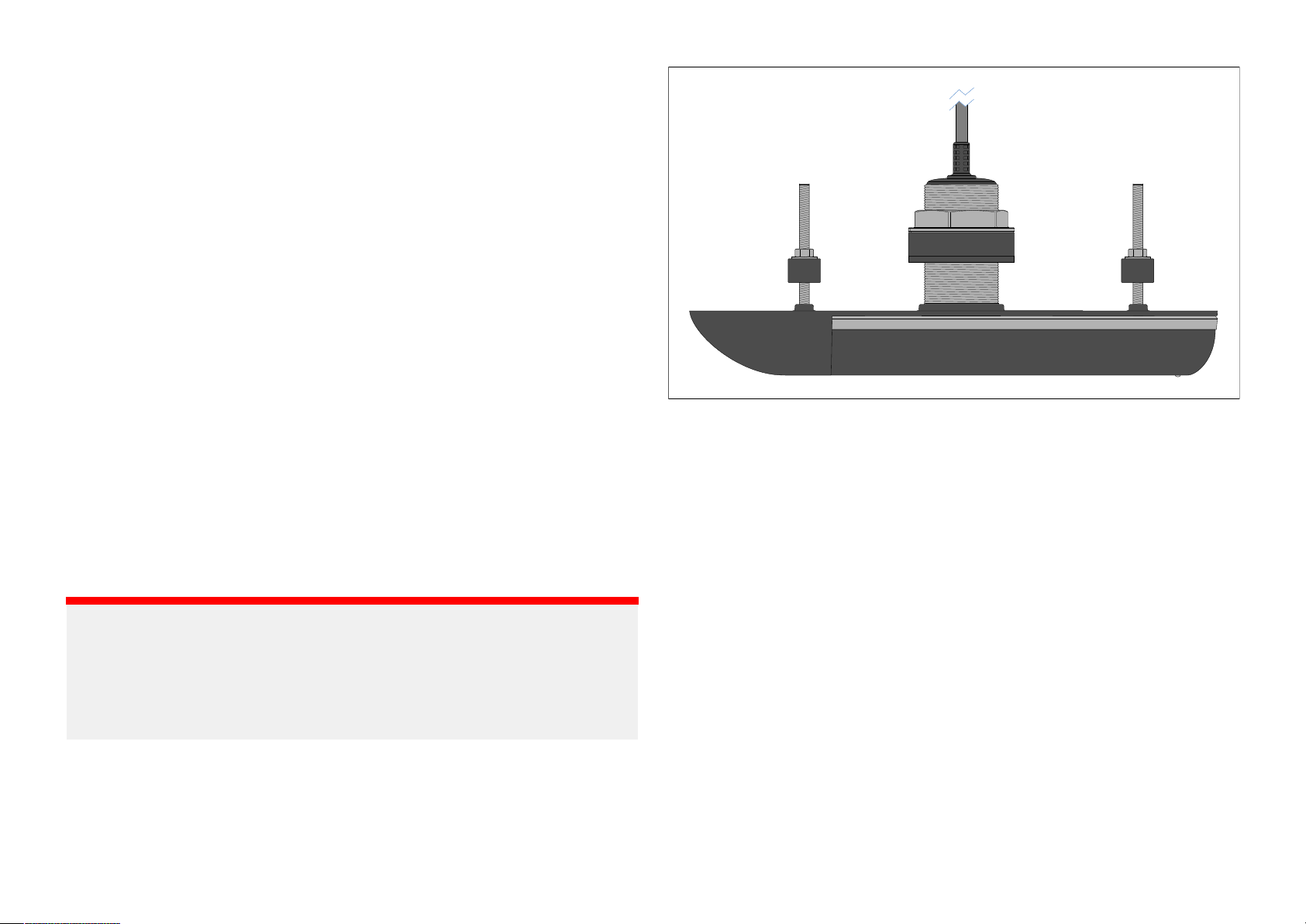
TheRVM-4xxseriestransducersareRealVision™Max3Dstainlesssteel
thru-hulltransducers.
InconjunctionwithaRealVision™Max3Dcompatiblemultifunctiondisplay
orsonarmodule,theRVM-4xxseriestransducersproducerealistic3D
representationsoftheobjectsbelowyourvessel,tohelpyouidentify
underwaterstructuresandlocatefish.
RealVision™Max3Dtransducersbenefitfromimprovedpingratesandtighter
beamwidths,resultinginsharpersonarimages,detailedwrecks,anddistinct
fishtargets.RealVision™Max3Dtransducersalsoprovidehighercontrast
colorpalettesforaccentuatingtargets,allowingfishtargetstostandout
fromthewatercolumnnoise.
Sonarchannels:
•RealVision™Max3Dtransducersofferthefollowingsonarchannels:
–RealVision™Max3D
–SideVision™
–DownVision™
–ConicalHighCHIRP/LowCHIRP600W/200kHz
•RealVision™Max3Dtransducersincludeabuilt-inAHRS(Attitudeand
HeadingReferenceSystem)sensorthathelpsstabilize3Dimaging
automatically,bycompensatingforvesselmotion.
Stainlesssteeltransducersaresuitableforinstallationsonvesselswith
fiberglass,metalorwoodenhulls.
Thetransducersdifferinternally,andcontaindifferentnumbersandtypes
oftransmitandreceiveelements.Y ourinstallationshouldcompriseeither
asingleRVM-400transducer,orasplit-pairofRVM-412sorRVM-420s
transducers.
Thehullgeometryofyourvesseldeterminesthemostappropriate
transducerstouse.Y oushouldfittransducerswhoseelementsareangledto
matchwithin±6°ofyourhull’sdeadriseangle,asdetailedbelow:
•RVM-400RealVision™Max3Dstainlesssteel0°(fordeadrise0°to6°)
thru-hullall-in-onetransducer(Partnumber:A80704)
Important:
•Wheninstallingthetransduceronavesselthathasametalhullyou
mustuseALLofthesuppliedisolatorpartstoensurethetransducer
metalworkisfullyisolatedfromthemetalhull.
•DoNO Tinstallstainlesssteeltransducersonvesselswithapositive
groundsystem.
Thesetransducersarecapableofproducing3Dsonarimageswhen
connectedtoaR ealVision™Max3DvariantMFDrunningLightHouse™4
software,oraLightHouse™4compatibleMFDusedinconjunctionwithan
RVM1600RealVision™Max3Dsonarmodule.TheRVM-4xxseriesincludes
5transducervariants,eachhavingthesameexternalshapeanddimensions.
Productandsystemoverview
•RVM-412PortandRVM-412StarboardRealVision™Max3Dstainlesssteel
12°(fordeadrise6°to18°)thru-hullsplit-pairtransducers(Systempack
partnumber:T70543)
–RVM-412Portporttransducer(Partnumber:A80705)
–RVM-412Starboardstarboardtransducer(Partnumber:A80706)
•RVM-420PortandRVM-420StarboardRealVision™Max3Dstainless
steel20°(fordeadrise14°to26°)thru-hullsplit-pairtransducer(System
packpartnumber:T70544)
–RVM-420Portporttransducer(Partnumber:A80707)
–RVM-420Starboardstarboardtransducer(Partnumber:A80708)
13
Page 14

ealVision™Max3Doverview
R
RealVision™Max3Dtransducersofferthefollowingrangeofimprovements
overRealVision™3Dtransducers:
•Improvedpingratesandtighterbeamwidths,resultinginsharpersonar
images,detailedwrecks,anddistinctfishtargets.
•HigherresolutionDownVisionandSideVisionimaging,combinedwith
highercontrastcolorpalettes—makingiteasiertoidentifystructure,and
allowingfishtargetstostandoutfromthewatercolumnnoise.
•Moreaccuratetargetlocationcapability,makingiteasiertopinpointthe
positionofawreckorsetupadrift.
•New600WHighCHIRPfrequencyprovidesdeepertraditionalsonar
rangeandstrongertargetreturns.
RealVision™3DMaxscreenexample
Note:
Thelistedsonarchannelrangesareindicativeonly
dependingonthetransducerinuse,theinstallation,andtheprevailing
waterconditions.
R
Sonarchannel
CHIRPsonar:
Vision™:
Down
SideVision™:
RealVision™Max3D:
ange
.6m(2ft)to366m(1,200ft)
0
0.6m(2ft)to183m(600ft)
0.6m(2ft)to91m(300ft)
0.6m(2ft)to91m(300ft)
,andmaydiffer
Compatiblesonarmodulesanddisplays
Transducersmustbeconnectedtoacompatiblesonarmoduletointerpret
andtransmitthesonarimagetoadisplayscreen.Thesonarmodulemaybe
externalorinternal(built-in)tothedisplay.
Y ourtransduceriscompatiblewiththefollowingsonarmodules:
•Axiom™2ProrangeofMFDs,whichincludeacompatibleinternalsonar
module.
•RVM1600RealVision™Max3Dexternalsonarmodule.
Sonarrange
Thesonarrangeistheeffectivedepthordistancethatthetransducercan
operateto
ThefollowingrangesapplytoRealVision™Max3Dsonarchannels:
14
,inoptimumweatherconditions.
Note:
ThetransducerisNOTcompatiblewiththeRVX1000RealVision™3D
externalsonarmodule,ortheinternalsonarmodulesbuilt-intoAxiom™,
Axiom™+andAxiom™ProMFDs.
RealVisiontransducerextensioncables
Transducersaresuppliedwithafittedcable,forsomeinstallations(including
allsplit-pairtransducerinstallations)itmaybenecessarytoextendthelength
ofthetransducercable.
Note:
•Forbestperformance,cablerunsshouldbekepttoaminimum.
•OnlyuseRaymarine®transducerextensioncables.
Raymarine®offershefollowingoptionalextensioncablesareavailable:
Page 15

ealVision™transducerextensioncable3m(9.8ft)(partnumberA80475)
•R
•RealVision™transducerextensioncable5m(16.4ft)(partnumberA80476)
•RealVision™transducerextensioncable8m(26.2ft)(partnumberA80477)
Splitpairtransducers:Extensioncablesfittedbetweenthetransducerand
the‘Y’cablemustbefittedinequallengthpairs(i.e.:eachtransducer’sfinal
cablelengthmustbethesame).
arning:Maximumtransducercablelength
W
ThemaximumlengthofcablebetweenaRealVision™Max
3DtransducerandaMFD/sonarmodule(includingthe
transducer’scaptivecable)mustNOTexceed18m(59ft).
Cablelengthsgreaterthanthismaycausedamagetothe
RealVision™Max3DtransducerandMFD/sonarmodule.
Productandsystemoverview
15
Page 16

CHAPTER4:P
CHAPTERCONTENTS
ARTSSUPPLIED
•4.
1Partssupplied—RVM-4xxseriestransducers—page17
16
Page 17
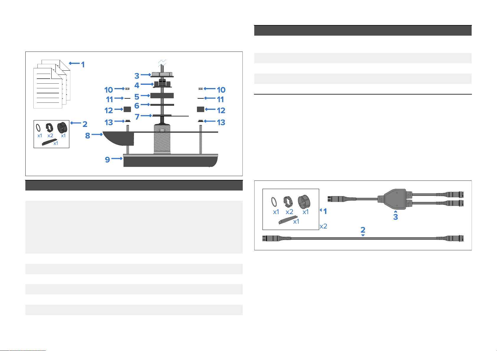
4.
1Partssupplied—RVM-4xxseriestransducers
Item
Description
ThefollowingpartsaresuppliedwitheachRVM-4xxseriestransducer.
Item
1Documentationpack
2
Description
L ockingcollarkit(fortransducercableconnector),consistingof:
9
102xNutsforanti-rotationstuds
11
122xSmallinternalisolatorsleeves
132xExternalisolatorsleeves
ransducer(includingfittedcable—refertolengthstated
T
below)
2xSmallwashersforAnti-rotationstuds
Transducercablelength
Thelengthofthecablefittedtothetransduceris:
•RVM-400—8m(26.2ft)
•RVM-412andRVM-420—2m(6.5ft)
Additionalpartssupplied
Thefollowingadditionalcablesaresuppliedwhenorderingasplitpairsetof
transducers.
•2xSplitrings(includesspare)
•1xO-ring
•1xLockingcollar
•1xSplitringfittingtool
3
4
5L argeinternalisolatorsleeve
6
7Externalisolatorplate
8
P artssupplied
Hullnut
Cableprotector
Rubberwasher
Highspeednosecone
17
Page 18

Item
Description
1
ockingcollarkit,consistingof:
2xL
•2xSplitrings(includesaspare)
•1xO-ring
•1xLockingcollar
•1xSplitringfittingtool
2
Extensioncable8m(26.2ft.),forconnectingthesingleendof
the“Y-cable
”adaptertoacompatibleMFDorsonarmodule.
3“Y-cable”adapterforconnectingasplitpairoftransducerstoa
singleextensioncable.Cablelength:0.3m(0.98ft.)
18
Page 19

CHAPTER5:PRODUCTDIMENSIONS
CHAPTERCONTENT
•5.
S
1T ransducerdimensions—RVM-4xx—page20
Productdimensions19
Page 20
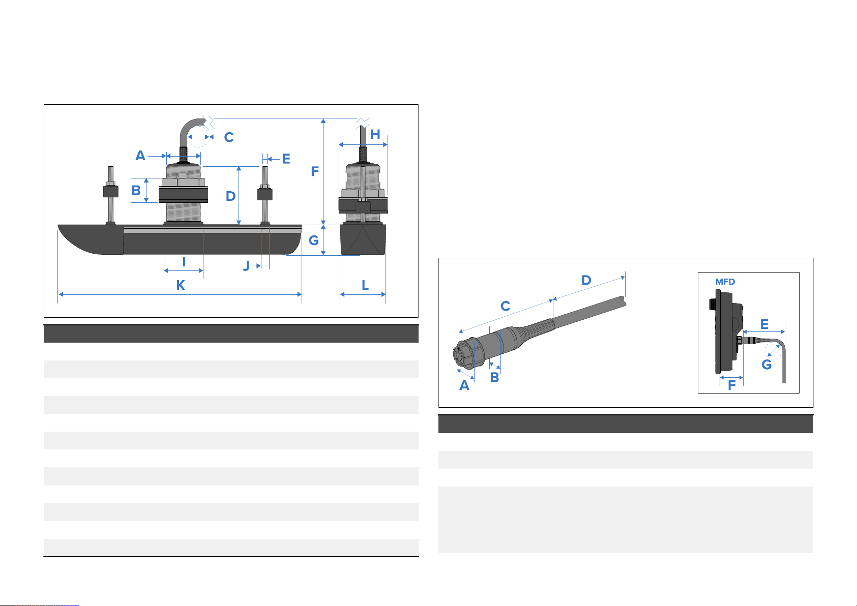
5.
1Transducerdimensions—RVM-4xx
Thedimensionsrelevantforinstallationareshownbelow.
AlltransducersintheRVM-4xxserieshavethesameexternaldimensions.
Nutsizes
•Hullnut—68mm(2¾in)acrossflats
•Anti-rotationnut—13mm(½in)acrossflats
T
ransducercablelength
Thelengthofthecablefittedtothetransduceris:
•RVM-400—8m(26.2ft)
•RVM-412andRVM-420—2m(6.5ft)
RealVisiontransducercableconnectordimensions
Thedimensionsofthetransducercableandcableconnectorareshown
below.
Cableconnectordimensions
Item
A
B
C
D
E
F
G
H
I
J
K
L
20
Dimension
60 .00mm(2.36in)
42.00mm(1.65in)
35.00mm(1.40in)
101.50mm(3.99in)
8.00mm(0 .31in)
170 .60mm(6.72in)
53.10mm(2.10in)
85.00mm(3.35in)
68.00mm(2.68in)
14.90mm(0 .59in)
424.69mm(16.72in)
79 .64mm(3.14in)
Item
A
B
C
D
Dimension
32.00mm(1.26in)
25.00mm(1.00in)
96.00mm(3.80in)
Cablelength:
•Single(All-in-one)transducerfittedcablelength:8m
(26.2ft).
•Splitpairtransducerfittedcablelength:2m(6.5ft).
Page 21

Item
Dimension
E
ThisdimensionisdependentonyourMFDvariant.R
yourMFDinstallationinstructions.
F
ThisdimensionisdependentonyourMFDvariant.R
yourMFDinstallationinstructions.
G
35.00mm(1.40in)
Note:
Forinstallationswherespacebehindthedisplayislimited,aright-angled
transducercableadaptorisavailable(A
80515).Usingtherightangled
cableadaptorwillreducedimensionEaboveby20mm(0.79in.)
eferto
eferto
Productdimensions
21
Page 22

CHAPTER6:L
CHAPTERCONTENTS
OCATIONREQUIREMENTS
•6.
•6.2Locationrequirements—page23
•6.3EMCinstallationguidelines—page25
1Warningsandcautions—page23
22
Page 23
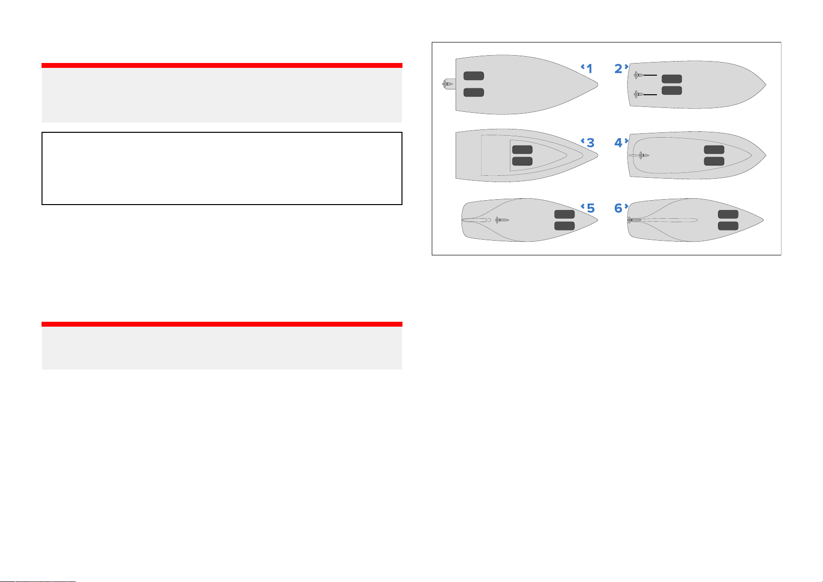
6.
1Warningsandcautions
Important:
Beforeproceeding,ensurethatyouhavereadandunderstoodthe
warningsandcautionsprovidedinthefollowingsectionofthisdocument:
.7—Importantinformation
p
arning:Switchoffpowersupply
W
Ensurethevessel’
startingtoinstallthisproduct.DoNOTconnectordisconnect
equipmentwiththepowerswitchedon,unlessinstructedin
thisdocument.
spowersupplyisswitchedOFFbefore
6.2L ocationrequirements
Followtheguidelinesbelowwhenselectingalocationforyoursingle
transducerorsplit-pairtransducers.
Forbestperformance,transducersshouldbeinstalledinalocationwiththe
leastturbulenceandaeration.
Important:
DoNO Tinstalltransducersin-linewithtrailerrollers,yourvessel’sengine
intakeordischargeopenings.
•T ransducersshouldbeinstalledasclosetothecenterlineofthevessel
aspossible.
1.OutboardorI/O(Planinghull)—mountforwardandtothesideof
thepropeller(s).
2.Inboard(Planinghull)—mountforwardofthepropeller(s)andshaft(s).
3.Steppedhull(Planinghull)—mountonthefirststepasfaraftas
possible.
4.Displacementhull—mountapproximately1/3ofthewayalongthe
lengthofthehull,measuredalongthewaterline.
5.Finkeel(Keelsailboat)—mountforwardofthekeel,ensuringthatthe
keelwillnotobstructthetransducerswidebeamwidth.
6.Fullkeel(Keelsailboat)—mountawayfromthekeelatalocation
withminimumdeadrise,ensuringthatthekeelwillnotobstructthe
transducerswidebeamwidth.
•Themountingsurfaceshouldbeflatsothattransducersitsflushagainst
thehull.
•Wheninstallingsplit-pairtransducerswithangledelements,youmust
ensurethatthehull’sdeadriseangleatthechosenmountinglocationis
appropriatefortheselectedtransducers.
•Whenfittingtoahullwithakeel,ensurethatthetransducerbeamwillnot
beobstructedbythekeel.Ifthetransducercannotbefittedforeoraftof
thekeelthenusesplitpairtransducerstoovercometheobstruction.
L ocationrequirements
23
Page 24
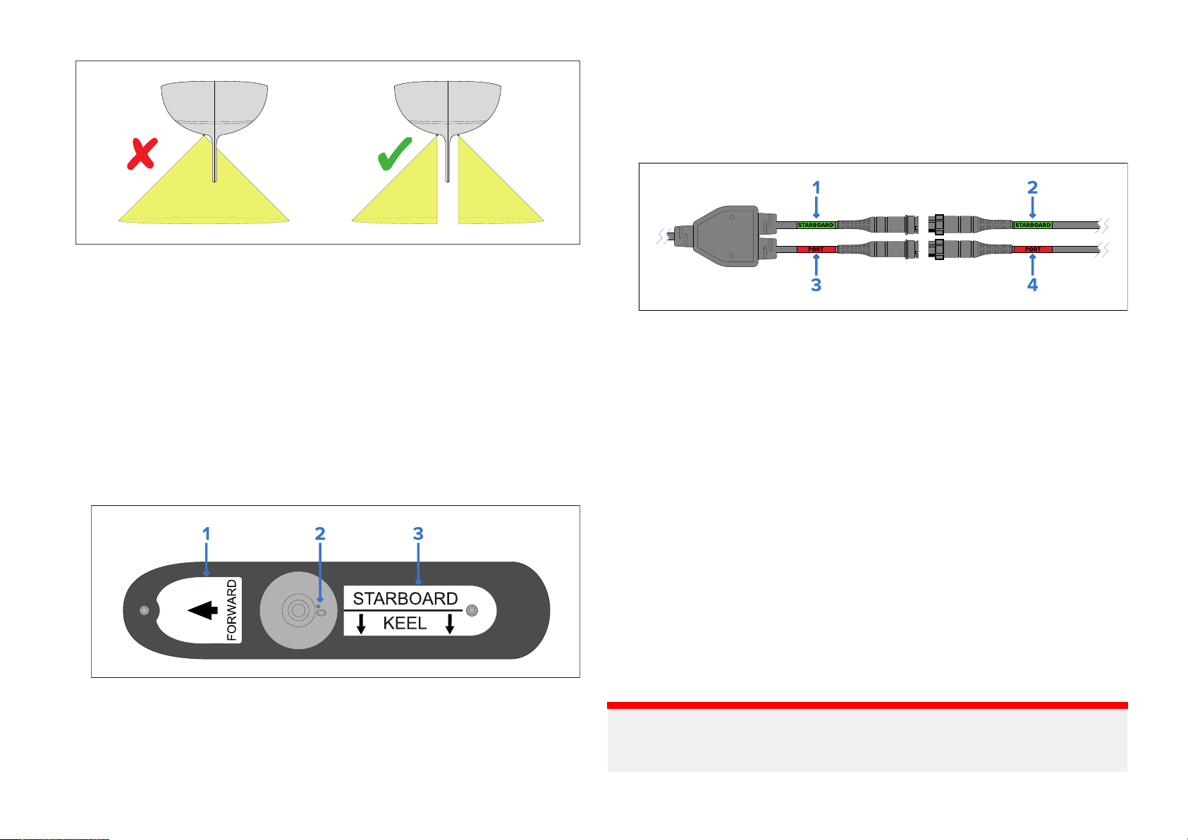
•Thetransducersshouldbeinstalledawayfromanyprotrusionssuchas
othertransducers,steps,ribs,strak es,orrowsofrivets.
•Transducersshouldbeinstalledinalocationwherenoloadwillbeapplied
tothetransducersduring,launching,lifting,traileringandstorageofthe
boat.
•Transducersmustbeinstalledinthecorrectorientation,withthe
anti-rotationboltclosesttothesternofthevessel.Additionally,adirection
arrowpointingtothebowisembossedontheanti-rotationboltcap.
•Wheninstallingsplit-pairtransducers:
–thecorrecttransducer(portorstarboard)mustbeinstalledinthe
matching(portorstarboard)sideofthehull.Thetransducershavelabels
onthetopfacethatidentifywhichsidetheyshouldbeinstalledonand
thetransducer’selementangle:
♦Splitpair—port,“P”orstarboard,“S”)
3.Splitpair—Vesselsideanddirectiontovesselkeel(Singleall-in-one
transducersdonotincludethislabel.)
–eachtransducerinasplitpairhavelabelsonthetransducercablesand
alsolabelsontheaccompanying‘Y’cablewhichidentifytheside:
1.Green—Starboard-sideYcable.
2.Green—Starboardsidetransducercable.
3.Red—PortsideYcable.
4.Red—Portsidetransducercable.
–choosemountingpositionsthataresymmetricaboutthecenterlineof
thevessel.
–choosemountingpositionsthatareatleast300mm(12inches)below
thewaterline.
•Transducersshouldbeinstalledinalocationwherethereissufficient
clearanceinsidethehulltofitthenutandhaveatleast100mm(4in)of
headroomtoallowforwithdrawal.
•Toavoidinterferencewiththeinternalmagnetometer,mounttransducers
atleast1m(39inches)fromotherelectricaldevices.
1.Directiontovesselbow
2.Elementangleandvesselside:
♦Single(all-in-one)transducersaremark
♦Splitpair(“12°”or“20°”)
24
Coredfiberglasshullmounting
Itisrecommendedthatthetransducerismountedinanon-coredsection,if
installationinacoredsectionisrequiredthentheareaaroundtheholemust
beadequatelystrengthenedtoensureitisnotdamagedwhentightening
thehullandanti-rotationnuts.
Important:
ed“0°”
Installationinacoredfiberglasshullshouldonlybecarriedoutbya
competentmarineinstaller.
Page 25
W
arning:2personinstallationrequired
T
opreventpotentialproductdamage,vesseldamageand
personalinjury2-personinstallationisrecommended.
6.3EMCinstallationguidelines
R
aymarine®equipmentandaccessoriesconformtotheappropriate
ElectromagneticCompatibility(EMC)regulations,tominimizeelectromagnetic
interferencebetweenequipmentandminimizetheeffectsuchinterference
couldhaveontheperformanceofyoursystem.
CorrectinstallationisrequiredtoensurethatEMCperformanceisnot
compromised.
Note:
Inareasofe xtremeEMCinterference,someslightinterferencemaybe
noticedontheproduct.Wherethisoccurstheproductandthesourceof
theinterferenceshouldbeseparatedbyagreaterdistance.
ForoptimumEMCperformancewerecommendthatwhereverpossible:
•R aymarine®equipmentandcablesconnectedtoitare:
Note:
Whereconstraintsontheinstallationpreventanyoftheabove
recommendations,alwaysensurethemaximumpossibleseparation
betweendifferentitemsofelectricalequipment,toprovidethebest
conditionsforEMCperformancethroughouttheinstallation.
–Atleast1m(3.3ft)fromanyequipmenttransmittingorcablescarrying
radiosignalse.g.VHFradios,cablesandantennas.InthecaseofSSB
radios,thedistanceshouldbeincreasedto2m(6.6ft).
–Morethan2m(6.6ft)fromthepathofaradarbeam.Aradarbeam
cannormallybeassumedtospread20degreesaboveandbelowthe
radiatingelement.
•Theproductissuppliedfromaseparatebatteryfromthatusedforengine
start.Thisisimportanttopreventerraticbehavioranddatalosswhichcan
occuriftheenginestartdoesnothaveaseparatebattery.
•Raymarine®specifiedcablesareused.
•Cablesarenotcutorextended,unlessdoingsoisdetailedinthe
installationmanual.
L ocationrequirements
25
Page 26

CHAPTER7:INS
CHAPTERCONTENTS
TALLATION
•7
•7.2Testingthetransducer—page27
•7.3Transducermounting—page28
.1T oolsrequired—page27
26
Page 27
7
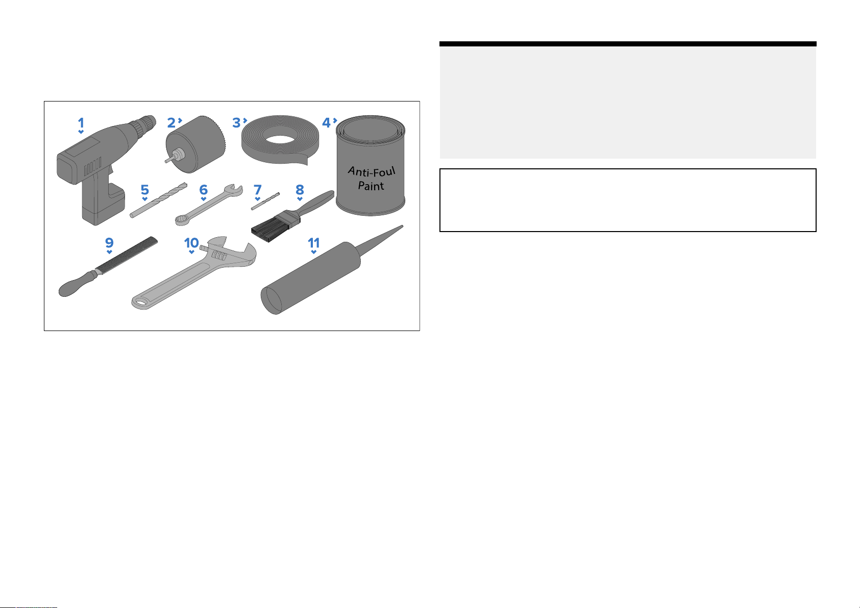
.1Toolsrequired
Note:
Thefollowingtoolsarerequiredtoinstallanyofthetransducerslistedunder
“Applicableproducts”.
1.P owerdrill
2.Holecuttersuitablefor68mm(2
3.Masking/adhesivetape
4.Waterbasedanti-foulingpaint
5.Drillbitsuitablefor15mm(19/32inch)externalisolatorsleeveboss)
6.13mm(½inch)wrench(spanner)orsuitablesizeadjustablewrench
(spanner)
7.Drillbit(suitableforpilotholes)
8.Paintbrush(forapplicationofanti-foulingpaint)
9.Halfroundfile
10.Largeadjustablewrench(spanner)suitableforhullnut68mm(2¾inch)
11.Marinegradesealant
43
/64inch)externalisolatorplateboss
(1)Itisrecommendedthatyoucutholesthesamesizeasthestatedvalues
andthen,ifnecessary
correctly.
Ifaholecutter/drillbitofthespecifiedsize(s)isnotavailable,useaslightly
smallersizeandthencarefullyfiletheholetothecorrectsize.Alternatively,
forlargerholes,youcoulduseajigsawtocuttheholeandthencarefully
filetheedgetocreateacircletherequiredsize.
,carefullyfiletheholetoallowpartstobefitted
Warning:Marine-gradesealant
Onlyusemarine-gradeneutralcurepolyurethanesealants.
DoNOTusesealantscontainingacetateorsilicone,whichcan
causedamagetoplasticparts.
7.2Testingthetransducer
Transduceroperationshouldbecheckedbeforeinstallation.Forthe
purposesofthistestyoudonotneedtoassemblytheconnectorlocking
collar.
FordetailedinformationonusingtheFishfinder/Sonarapppleasereferto
(1)
(1)
theoperationinstructionsforyourMFD.
1.ConnectthetransducertotherelevantconnectoronyourMFDorsonar
modulethatisconnectedtoyourMFD.
2.Fullysubmergethetransducerinwater.
3.PowerupyourMFDand/orSonarmodule.
4.OpenaFishfinder/SonarapponyourMFD.
5.Ifrequired,selecttherelevanttransducerfromtheTransducersettings
tab([Menu>Transducer>Transducer]).
6.Ifrequired,selecttherelevantchannelfromtheChannelselectionoptions
([Menu>Allchannels]).
7.Checkthataccuratedepthandwhereapplicabletemperaturereadings
aredisplayed.
8.IfyouexperiencedifficultiesobtainingreadingsthencontactRaymarine®
TechnicalSupport.
Installation
27
Page 28
W
arning:Transduceroperation
Onlytestandoperatethetransducerinthewater
operateoutofwaterasoverheatingmayoccur.
.3Transducermounting
7
Themountingprocedurebelowshouldbereadthoroughlybeforeattempting
tomountthetransducer.
Stainlesssteeltransducersaresuitableforinstallationsonvesselswith
fiberglass,metalorwoodenhulls.
Important:
•Y oumustuseALLofthesuppliedpartswheninstallingthetransducer.
•Wheninstallingthetransduceronavesselthathasametalhullthe
suppliedisolatorpartsensurethatthetransducermetalworkisfully
isolatedfromthemetalhull.
•DoNOTinstallstainlesssteeltransducersonvesselswithapositive
groundsystem.
.DoNOT
Drillingholesinthehull
oinstallathru-hulltransduceryoumustdrill3holesinthehullofyourvessel.
T
Y oushouldusethesuppliedmountingtemplatetomarktheholelocation.
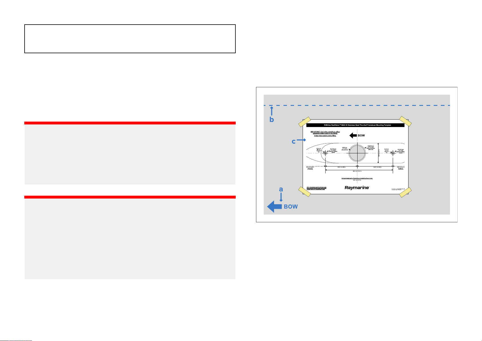
1.Ensurethatyouareusingthecorrecttransducer(i.e.:port/starboard,0°,
12°or20°tiltedelement)foryourchosenmountinglocation.
2.Usingself-adhesivetape,attachthesuppliedmountingtemplatetoyour
chosenmountinglocation,ensuringthat:
Important:
•Onlyperformtheinstallationwithyourvesseloutofthewater .
•DoNOTliftorsuspendthetransducerusingitscable.
•Ensurethatthetransducerbodyissupportedduringinstallation.
•DoNOTremovethelabelattachedtothetransducercable;asithelpsto
ensurecorrectconnection.
•DoNOTovertightenthehullnutoranti-rotationbolt.Overtightening
cancausedamagetothehullwhichmayresultinwaterleakinginto
thevessel.
28
i.the‘Bow’arrowonthetemplateispointedtowardsthevessel’sbow.
ii.themountingtemplateisparalleltothecenterlineofthevessel.
iii.thetemplateisflatandnotcreased.
3.Piercethetemplateateachholecenterandmarktheholelocationson
thehullusingapencilormarker..
4.Removethetemplatefromthehull.
5.Drillapilotholeforthetransducerstemhole.
(1)
6.
Drillaholesuitableforthe68mm(2
externalisolatorplate.Thebossontheexternalisolatorplatemustsit
insidethehull.
43
/64inch)bossonthetopofthe
Page 29
Important:
(1)Itisrecommendedthatyoucutholesthesamesizeasthestatedvalues
andthen,ifnecessary
,carefullyfiletheholetoallowpartstobefitted
correctly.
Ifaholecutter/drillbitofthespecifiedsize(s)isnotavailable,useaslightly
smallersizeandthencarefullyfiletheholetothecorrectsize.Alternatively,
forlargerholes,youcoulduseajigsawtocuttheholeandthencarefully
filetheedgetocreateacircletherequiredsize.
7 .Usingahalfroundfileand/orsandpaper,ensuretherearenorough
edgesorburrsaroundthetransducerstemhole.
8.Drillthetwo15mm(19/32inch)holesfortheanti-rotationbolts.
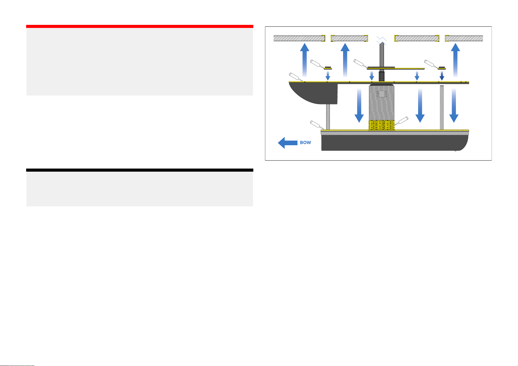
Assemblingtheexternalcomponents
Thestepsbelowwillguideyouthroughtheassemblyoftheexternal
components.
1.Ensurecorrectorientationusingthemarkingsandlabelsonthetopface
Note:
T oachievealonglastingwatertightseal,ensurethatallpartsareclean
anddryandapplyagenerousamountofmarine-gradesealanttoallmating
surfaces.
Installation29
ofthetransducer.
2.Removetheorientationlabelsandcleantoensurethereisnoresidual
labelglue.
3.Usinganappropriateclothandcleaningagent(forexample:isopropyl
alcohol),wipecleanALLsurfacesofthesuppliedcomponentsandthe
mountinglocation,bothoutsideandinsidethehullensuringthatthey
arefreefromgreaseanddebris.
4.Ensureallsurfacesaredry.
5.Applyathickbeadofmarine-gradesealantalloverthetopfaceofthe
transducersothatitiscompletelycovered.
6.Feedthetransducercable,stemandanti-rotationstudsthroughtheholes
inthehighspeednosecone,positioningthehighspeednoseconeover
thetransducer ,andthenslidethetransducerintothenose.
7.Applypressuretothehighspeednosecone,tocompressthesealant
againstthetransducer .
8.Feedthetransducercablethroughthestemholeintheexternalisolator
plate,andthenpositiontheexternalisolatorplateintherecessinthe
topofthehighspeednosecone.
9.Feedanexternalisolatorsleeveoverbothoftheanti-rotationstuds,
positioningthemintheholerecessesinthetopofthehighspeednose
cone.
Page 30
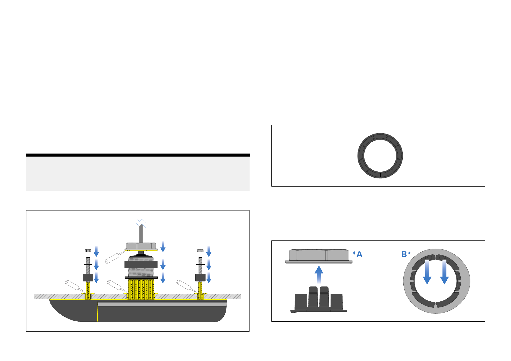
.Applyathickbeadofmarine-gradesealant:
10
i.alloverthetopfaceofthehighspeednosecone,externalisolator
plate,andexternalisolatorsleeves,ensuringthattheyarecompletely
covered.
ii.allaroundthebottompartofthethreadedsectionofthetransducer
stemandtheanti-rotationstuds,ensuringthatthesealantwillprotrude
approximately6mm(0.24in)abovethefinaltightenednuts.
iii.allaroundandinsidetheholesyouhavedrilledinthehull.
11.Guidethetransducercablethroughthelargestemholeinthehull.
12.Guidethetransducerstemandanti-rotationstudsupthroughtheholesin
thehull.
13.Supportthetransducerfrombeneath.
Assemblingtheinternalcomponents
Followthestepsbelowtofitthetransducertoyourhull.
Note:
T oachievealonglastingwatertightseal,ensurethatallpartsareclean
anddryandapplyagenerousamountofmarine-gradesealanttoallmating
surfaces.
1.Frominsidethevessel,applyacontinuous,thickbeadofmarine-grade
sealantallaroundthebaseoftheprotrudingtransducerstemand
anti-rotationboltthreads.
2.Guidetherubberwasherdownthetransducercable
threadedsectionofthetransducerstem,compressingthesealantsothat
therubberwashersitsflushonthehull.
3.Ifnecessary,applyadditionalmarine-gradesealanttothetransducer
stem,abovetherubberwasher.
4.Withthetopfacepointingupwards,guidethelargeisolatorbushdown
thetransducercableandoverthetransducerstem,ensuringitsitsflush
ontherubberwasher.
Largeisolatorbushtopface
,andoverthe
Mountingandsealantapplication
30
5.Ifnecessary,applyadditionalmarine-gradesealanttothetransducer
stem,abovethelargeisolatorbush.
6.Ensuringthecableprotectorisfittedtothehullnut,guidethenutdown
thetransducercable,restingthenutontopofthetransducerstem.
Cableprotectorfittingandremoval
•A—Fitting
Page 31
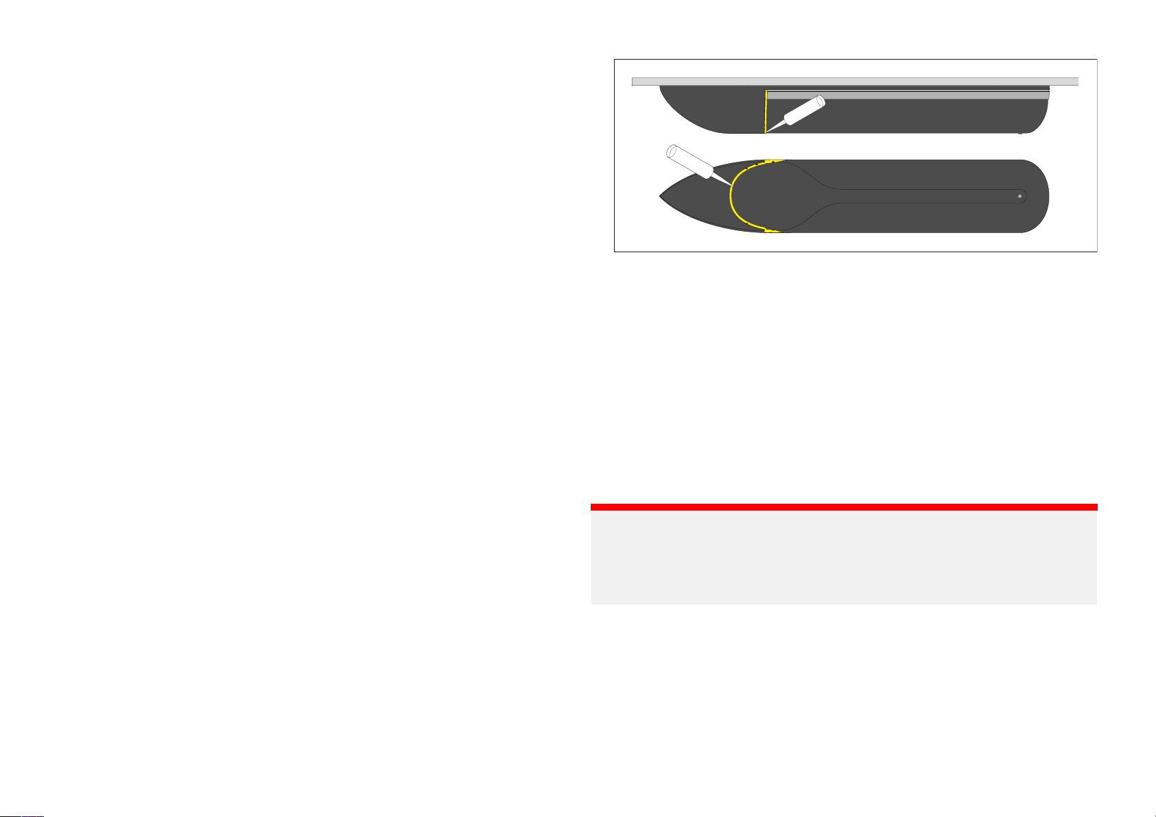
•B—R
emoval
7.Removethecableprotectorbypullingthe2tabsawayfromtheback
ofthehullnut.
8.Applyathickbeadofmarinegradesealanttothebottomfaceofthe
hullnut.
9.Screwthehullnutontothetransducerstemsothatitishandtight.
10.Fromoutsidethevesselensurethatthetransducerispushedfullyinto
thehighspeednosecone.
Itisrecommendedthatasecondpersonholdsthehighspeednosecone
inplacewhilstthestemandanti-rotationnutsarefullytightened.
11.Fullytighten,usinga70mm(2
3
/4inch)wrench(spanner)orlarge
adjustablewrench.
Ensurethatthehullnutisadequatelytightened.Y oushouldseethe
sealantprotrudingfromtheedgesofallappliedsurfaces.
2.Removeanyexcesssealantontheoutsideofthehullandtransducer,
ensuringasmoothtransitionbetweennoseconeandtransducer,and
transducerandhull.
3.Ensurethatthemarine-gradesealanthasfullycured
Refertothesealantmanufacturer’sinstructionsforcuringtimes.
12.Placethesmallinternalisolatorsleevesovertheanti-rotationstuds,
ensuringtheysitflushontheinteriorofthehull.
13.Ifnecessary,applyadditionalmarine-gradesealanttotheanti-rotation
studs,abovethesmallinternalisolatorsleeves.
14.Placethesmallwashersovertheanti-rotationstuds.
15.Ifnecessary,applyadditionalmarine-gradesealanttotheanti-rotation
4.Unlesslocalenvironmentalregulationsprohibit,applyawater-based
anti-foulingpainttothebottomfaceofthetransducer,ensuringallofthe
externallyexposedtransducersurfacesarecoatedandthepaintoverlaps
ontothehull.
5.Checkforleaksaroundthetransducerimmediatelyuponputtingthe
vesselbackinthewater.
studsabovethesmallwasher.
16.Screwtheanti-rotationnutsontothestudsandfullytighten,usinga
13mm(1/2inch)wrench(spanner)oradjustablewrench.
Important:
DoNOTleaveyourvesselinthewateruncheckedafterinstallingyour
transducer.Verysmallleaksmaynotbeimmediatelyobvious,anda
Finalizingtheinstallation
considerablevolumeofbilgewatercouldaccumulateoverthecourseof
aday,orovernight.
Followthestepsbelowtofinalizetheinstallationofyoutransducer.
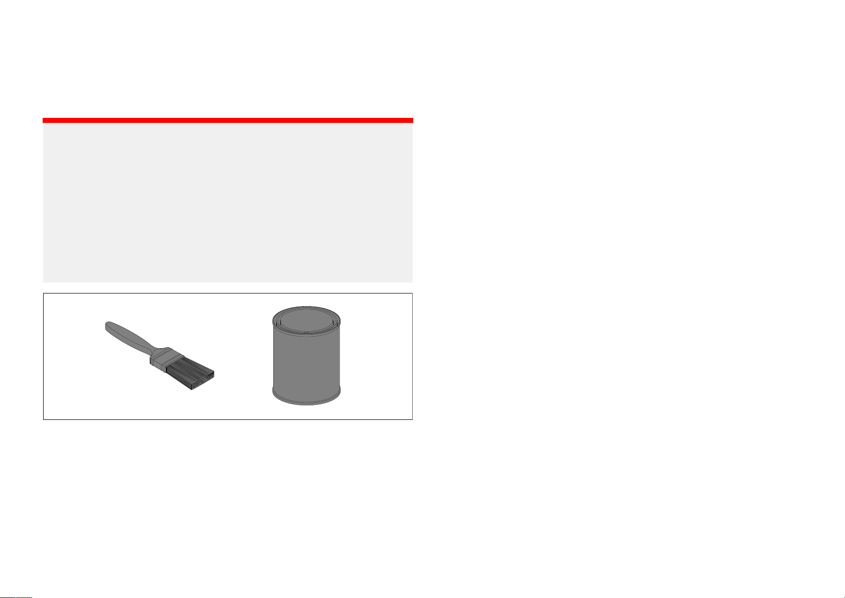
1.Applyathickbeadofmarine-gradesealantinthegapbetweenthe
transducerandnoseconeonthebottomandbothsides,asshownbelow.
6.Checkforleaksatregularintervalsafterinstallation,untilyouaresatisfied
thattherearenoleaks.
7.Addaregularcheckforleaksaroundthetransducertoyourroutine
vesselmaintenanceschedule.
Installation31
Page 32
Anti-fouling
Wherelocalregulationsallow
,itisrecommendedthatyoucoatyour
transducerusingawater-basedanti-foulingpaint.Thiswillhelppreventthe
build-upofbarnaclesandotherorganicgrowth,whichcancauseincreased
dragthatwilldegradesonarperformance.
Important:
•Beforeapplyingwater-basedanti-foulingpaint,checkthatlocal
environmentalrulesandregulationsdonotprohibittheuseofanti-fouling
paint.
•Neverusecopper-basedanti-foulingpaintasthiscanimpacttransducer
performance
.
•Neveruseketone-basedanti-foulingpaintasthiscanattackthe
transducer’splastic,damagingthetransducer .
•Paintyourtransducerusingabrush,donotuseaspraycanorasponge
rollerasthesemethodscancausetinyairbubblestobeincorporatedin
thepaint,whichwillalsoreducetransducerperformance.
Theanti-foulingpaintshouldbeappliedinathinandevencoatcoveringall
e xternallyexposedtransducersurfaces.
Y oushouldcleanyourtransducerregularlyandre-applyanti-foulingpaint
every6months,orsoonerdependingonhowrapidlyorganicgrowthbuilds
up.
32
Page 33

CHAPTER8:C
CHAPTERCONTENTS
ABLESANDCONNECTIONS—GENERALINFORMATION
•8.
1Generalcablingguidance—page34
Cablesandconnections—Generalinformation33
Page 34

8.
1Generalcablingguidance
Cabletypesandlength
Itisimportanttousecablesoftheappropriatetypeandlength.
•UnlessotherwisestatedonlyusecablessuppliedbyRaymarine.
•Whereitisnecessarytousenon-Raymarinecables,ensurethattheyareof
correctqualityandgaugefortheirintendedpurpose.(e.g.:longerpower
cablerunsmayrequirelargerwiregaugestominimizevoltagedropalong
therun).
Strainrelief
Useadequatestrainreliefforcablingtoensurethatconnectorsareprotected
fromstrainandwillnotpulloutunderextremeseaconditions.
Cableshielding
Ensurethatcableshieldingisnotdamagedduringinstallationandthatall
cablesareproperlyshielded.
Caution:Transducercable
•DoNOTusethetransducercabletoliftorsuspendthe
transducer;alwayssupportthetransducerbodydirectly
duringinstallation.
•DoNOTcut,shorten,orsplicethetransducercable.
•DoNOTremovetheconnector .
Ifthecableiscut,itcannotberepaired.Cuttingthecablewill
alsovoidthewarranty.
34
Page 35

CHAPTER9:CONNECTIONS
CHAPTERCONTENT
•9
.1Cablerouting—page36
S
•9.2Attachingtheconnectorlockingcollar—page36
•9.3RVM-400connection—page37
•9.4RVM-412/RVM-420connection—page37
•9.5RealVisiontransducerextensioncables—page38
•9.6Makingconnections—page38
Connections35
Page 36
9
.1Cablerouting
Important:
Cableroutingrequirementsforthetransducercable.
Important:
T
oavoidinterference,thecablemustberoutedasfarawayfromVHF
radioantennacablesaspossible.
Important:
Thetransducercable
assembly.Ensurethatyouroutethecableallthewaytoyourcompatible
sonarmoduleorMFDbeforeattachingthelockingcollar.
•Checkthatthecableislongenough.Ifyouareinstallingsplit-pair
transducers,youmustuseaY-cable(A 80478)alongwithanextension
cabletoconnectthetransducerstoyourtoyourcompatiblesonarmodule
orMFD.
•Usegrommetsinanypass-throughholestopreventdamagetothe
transducercable.
•Securethecableatregularintervalsusingsuitablecableclips(not
supplied).
•Takecarenottoapplyexcessivestraintothecablewhereitleavesthe
transducer.Wherepossible,allowthecabletolaynaturallyasitleavesthe
transducer,beforesecuringitwithcableclips.
’sconnectorissuppliedwithaseparatelockingcollar
Ensurethatyouroutethecableallthewaytoitsdestinationbefore
attachingthelockingcollar
.
•Donotbendthetransducercablebeyonditsminimumbendradius.Thisis
particularlyimportantatthepointwherethecableleavesthetransducer.
•Anyexcesscableshouldbecoiledupataconvenientlocation.
9.2Attachingtheconnectorlockingcollar
Thesuppliedcableisprovidedwithaseparatelockingcollarassembly,
ensuringthatthecableconnectionissecure.
Thisproceduredescribeshowtoattachthelockingcollartothecable
connector.Thelockingcollarpartsaresuppliedinaseparatebag,inthe
packagewithyourproduct.
36
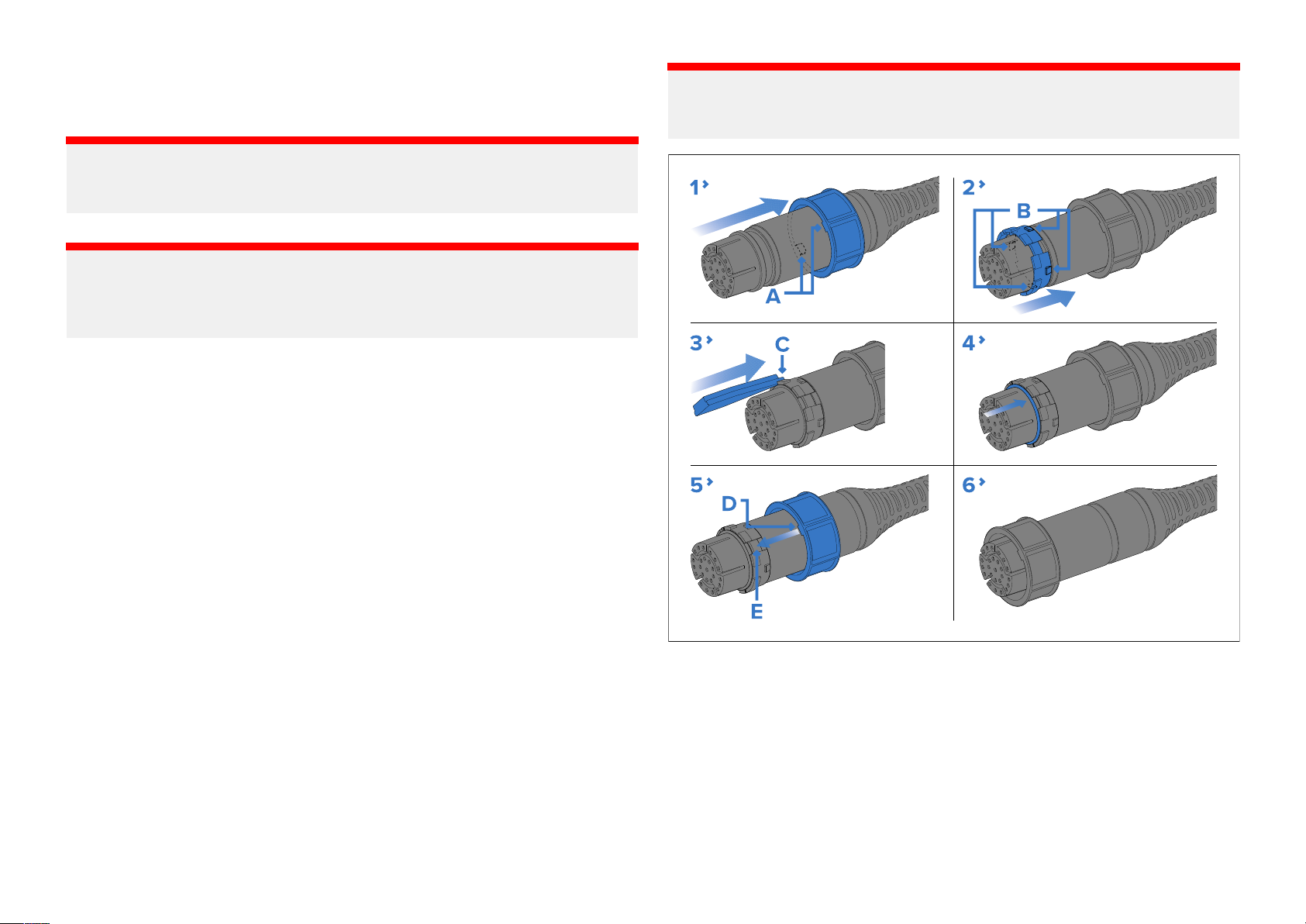
1.Slidethelockingcollarovertheendoftheconnector,thenpushit
towardsthecable-endoftheconnector.Ensurethatthelugsonthe
lockingcollar(labelled‘A’intheillustration),areclosesttotheplug-endof
theconnector.
2.Slidethesplit-ringovertheendoftheconnector,thenpushittowardsthe
cable-endoftheconnector.Ensurethatthetabsonthesplit-ring(labelled
‘B’intheillustration),areclosesttothecable-endoftheconnector.
Thesplit-ringslideseasilyforapproximately1cm(0.39in)ontothe
connector,beforebuttingupagainsttheconnectormoulding.
Page 37
3.Carefullyinsertthepointedendofthesuppliedtoolintothesplit-ring’
gap(labelled‘C’intheillustration).Usethetooltogentlyleverthesplit
ringoverthemouldingontheconnectoruntilitsnapsintoposition
approximately0.5cmfurtherbacktowardsthecable-endofthe
connector.
Alwaysusethesuppliedtoolwhenattachingthesplitring.Thesplitring
maybecomeoverstretchedandbreakifyoutrytoattachitwithoutusing
thetool.Asparesplitringissuppliedwiththelockingcollarassembly,
incaseofbreakage.
4.SlidetheO-ring(arrowed)overtheendoftheconnector,andensure
thatitisseatedsquarelyagainsttheconnectormoulding,adjacentto
thesplit-ring.
5.Slidethelockingcollartowardstheplug-endoftheconnector,rotating
thecollarasnecessarytoensurethatthelugsonthelockingcollar
(labelled‘D’intheillustration)passthroughthechannels(labelled‘E’)
inthesplit-ring.
Thelockingcollarslideseasilytowardstheplug-endoftheconnector,
beforebuttingupagainstthesplit-ringmoulding.
6.Graspthebodyoftheconnectorwithonehand,thenwiththeotherhand,
pullthelockingcollarfirmlytowardstheplug-endoftheconnector .
Asyoupullthelockingcollar,itclicksintoplaceoverthesplit-ring.The
lockingcollarstaysinpositionontheconnector,butrotatesfreely.
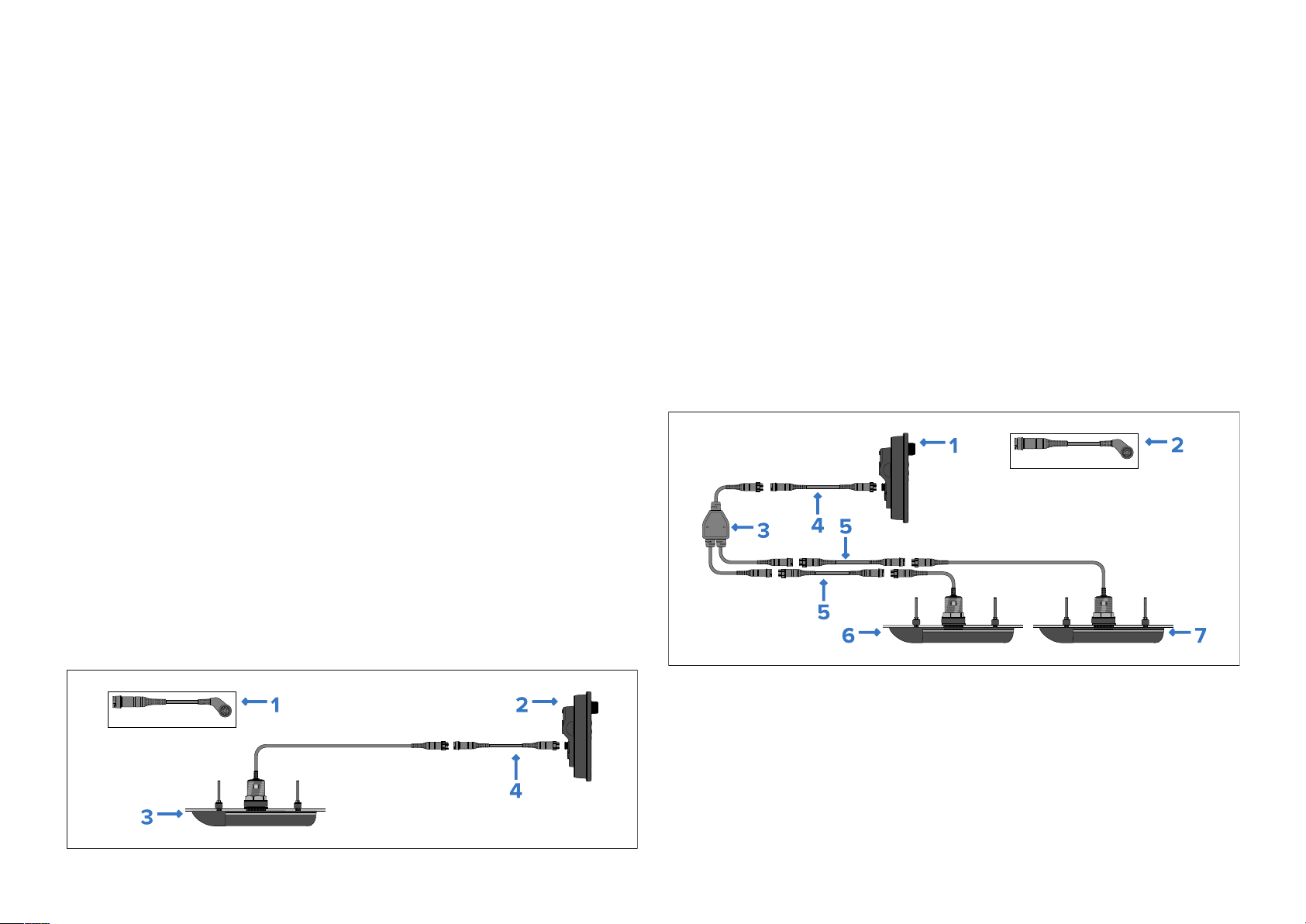
s
1.Optionalright-angledadaptor(A
reducethespacerequiredbehindanMFD).
2.CompatibleMFDorsonarmodule.
3.Transducer .
4.T oextendthecablerun,optionalextensioncablescanbefittedbetween
thetransducerandtheMFDorsonarmodule.
•ForcompatibleMFDandsonarmodulesreferto:
p.14—Compatiblesonarmodulesanddisplays
•Fordetailsonextensioncablesreferto:
p.38—RealVision™Max3Dtransducerextensioncables
80515),suppliedseparately(usedto
9.4RVM-412/RVM-420connection
SplitpairtransducersareconnectedtotheMFDorsonarmoduleusingthe
supplied‘Y’cableandextensioncable.
9.3RVM-400connection
Theall-in-onetransducercanbeconnecteddirectlytotheMFDorsonar
module.
1.CompatibleMFDorsonarmodule.
2.Optionalrightangledadaptor(A80515)suppliedseparately(usedto
reducethespacerequiredbehindanMFD).
3.‘Y’cable(supplied)
4.8m(26.2ft)extensioncable(supplied)
5.Optionalextensioncablescanbefittedbetweenthetransducerand
‘Y’cableifrequired,orbetweensuppliedextensioncableandMFDor
sonarmodule.
Connections37
Page 38
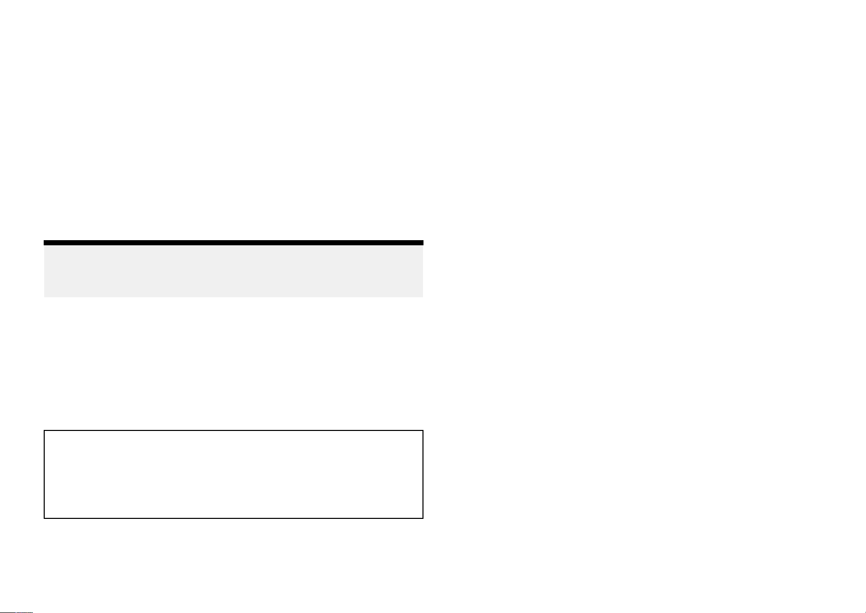
ransducer,e.g.:RVM-412Port.
6.T
7.Transducer,e.g.:RVM-412Starboard.
•ForcompatibleMFDandsonarmodules,referto:
p.14—Compatiblesonarmodulesanddisplays
•Fordetailsonextensioncables,referto:
p.38—RealVision™Max3Dtransducerextensioncables
9.5RealVisiontransducerextensioncables
Transducersaresuppliedwithafittedcable,forsomeinstallations(including
allsplit-pairtransducerinstallations)itmaybenecessarytoextendthelength
ofthetransducercable.
Note:
•Forbestperformance ,cablerunsshouldbekepttoaminimum.
•OnlyuseRaymarine®transducerextensioncables.
R aymarine®offershefollowingoptionalextensioncablesareavailable:
•RealVision™transducerextensioncable3m(9.8ft)(partnumberA80475)
9
.6Makingconnections
FollowthestepsbelowtoconnectthetransducercabletoaRealVision™Max
3Dsonar-capabledevice(i.e.:Axiom™2ProMFDorRVM1600sonarmodule).
1.Ensurethatthevessel'spowersupplyisswitchedoff.
2.Connectcablesasfollows:
i.ConnectthecablefromeachtransducertotheY-cabletails(A80478);
checkthecoloredlabelsonthecablestoensurethatthetransducers
areconnectedtothecorrectY-cabletail.
ii.ConnectanextensioncabletotheremainingfreeplugontheY-cable.
Seep.38—RealVision™Max3Dtransducerextensioncables.
3.Ensuringcorrectorientation,pushthetransducercable(orextension
cable)connectorfullyontothecorrespondingconnectoronyourMFD
orsonarmodule.
4.Turnthelockingcollarclockwisetosecurethecable.
•RealVision™transducerextensioncable5m(16.4ft)(partnumberA80476)
•RealVision™transducerextensioncable8m(26.2ft)(partnumberA80477)
Splitpairtransducers:Extensioncablesfittedbetweenthetransducerand
the‘Y’cablemustbefittedinequallengthpairs(i.e.:eachtransducer’sfinal
cablelengthmustbethesame).
Warning:Maximumtransducercablelength
ThemaximumlengthofcablebetweenaRealVision™Max
3DtransducerandaMFD/sonarmodule(includingthe
transducer’scaptivecable)mustNOTexceed18m(59ft).
Cablelengthsgreaterthanthismaycausedamagetothe
RealVision™Max3DtransducerandMFD/sonarmodule.
38
Page 39

CHAPTER10:S
CHAPTERCONTENTS
YSTEMCHECKSANDTROUBLESHOOTING
•10
.1RealVision™AHRScalibration—page40
•10.2Troubleshooting—page40
S ystemchecksandtroubleshooting
39
Page 40

10
.1RealVision™AHRScalibration
Note:
RealVision™transducersincludeabuilt-inAHRS(AttitudeandHeading
ReferenceSensor),whichmeasuresthemotionofyourvesseltoassistin
therenderingofsonarimages.AfterinstallationallRealVision™transducers
requirecalibration.
Anuncalibratedtransducercanproduceanoffsettothefrontedgeofthe
renderofthebottominthesonarimage,asillustratedbelow.
UncalibratedCalibrated
Calibrationisanautomaticprocessandstartsafteryourvesselhasturned
appro ximately100°ataspeedofbetween3–15knots.Calibrationrequires
nouserinput,howeveratleasta270°turnisrequiredbeforethecalibration
processcandeterminethelocaldeviationandapplyarelevantoffset.
Thetimeittakestocompletethecalibrationprocesswillvaryaccordingtothe
characteristicsofthevessel,theinstallationenvironmentofthetransducer,
andthelevelsofmagneticinterferenceatthetimeofconductingthe
process.Sourcesofsignificantmagneticinterferencemayincreasethetime
requiredtocompletethecalibrationprocess.Certainareaswithsubstantial
magneticdeviationmayrequireextracirclesor“figureof8”manoeuvresto
beperformed.Examplesofsuchsourcesofmagneticinterferenceinclude:
•Vesselengines
Insomecircumstances,itisbeneficialtodisableR
sourcesofmagneticinterferencearedistortingthesonarimage.Realvision
AHRScanbedisabledfrom[Settings].
[Menu>Settings>Sounder>AHRSstabilization]
Note:
TheCalibrationprocesswillrequirerepeatingaftera[Sonarreset]orMFD
[Factoryreset].
ealvisionAHRSiflocal
10.2Troubleshooting
Thetroubleshootingsectionprovidespossiblecausesandthecorrective
actionrequiredforcommonproblemsthatareassociatedwiththeinstallation
andoperationofyourproduct.
Beforepackingandshipping,allRaymarine®productsaresubjectedto
comprehensivetestingandqualityassuranceprograms.Ifyoudoexperience
problemswithyourproduct,thissectionwillhelpyoutodiagnoseandcorrect
problemstorestorenormaloperation.
Ifafterreferringtothissectionyouarestillhavingproblemswithyour
product,pleaserefertotheT echnicalsupportsectionofthismanualfor
usefullinksandRaymarine®ProductSupportcontactdetails.
Operationinstructions
Fordetailedoperationinstructionsforyourproduct,refertothe
documentationthataccompaniesyourdisplay.
AllproductdocumentationisavailabletodownloadfromtheRaymarine
website:www.raymarine.com/manuals.
•Vesselalternators
•Marinepontoons
•Metal-hulledvessels
•Underwatercables
40
Page 41

Sonartroubleshooting
P
ossiblecausesPossiblesolutions
Scrollingimageisnotbeingdisplayed
P
ossiblecausesPossiblesolutions
SonardisabledEnable[Ping]fromtheFishfinderapp
[Menu>Settings>Sounder>Pingenable].
Incorrecttransducer
selected
Damagedcables
Damagedorfouled
transducer
Checkthatthecorrecttransducerisselectedinthe
Fishfinderapp
’sTransducertab:[Menu>Settings
>Transducer].
1.Checkthatthetransducercableconnectoris
fullyinsertedandlockedinposition.
2.Checkthepowersupplycableandconnectors
forsignsofdamageorcorrosion,replaceif
necessary.
3.Withtheunitturnedon,tryflexingthecable
neartothedisplayconnectortoseeifthis
causestheunittore-boot/losepower,replace
ifnecessary.
4.Checkthevessel’sbatteryvoltage,the
conditionofthebatteryterminalsandpower
supplycables,ensuringconnectionsare
secure,cleanandfreefromcorrosion,replace
ifnecessary.
5.Withtheproductunderload,usinga
multi-meter,checkforhighvoltagedropacross
allconnectors/fusesetc(thiscancausethe
Fishfinderapplicationstostopscrollingorthe
unittoreset/turnoff),replaceifnecessary.
Checktransducercondition,ensuringitisnot
damagedandisfreefromdebris/fouling.If
necessary ,cleanorreplaceyourtransducer.
Aftercleaningorreplacementcoatthetransducer
usingawater-basedanti-foulingpaint.
’ssoundertab:
Externalsonar
module:network
connectionproblem.
Checkthattheunitiscorrectlyconnectedtoyour
displayornetworkswitch.Checkallconnectionsto
ensurethattheyaresecure
corrosion,replaceifnecessary.
Externalsonar
module:software
mismatchbetween
equipment
EnsureallRaymarine®productscontainthe
latestavailablesoftware,checktheRaymarine®
website:www.raymarine.com/softwareforsoftware
compatibility.
mayprevent
communication.
Nodepthreading/lostbottomlock
PossiblecausesPossiblesolutions
Transducerlocation
Transducerangle
Transducer
kicked-up
Powersource
insufficient
Damagedorfouled
transducer
Checkthatthetransducerhasbeeninstalledin
accordancewiththeinstructionsprovidedwiththe
transducer.
Ifthetransducerangleistoogreatthebeamcan
missthebottom,adjusttransducerangleand
recheck.
Ifthetransducerhasakick-upmechanism,check
thatithasnotkickedupduetohittinganobject.
Withtheproductunderload,usingamulti-meter ,
checkthepowersupplyvoltageasclosetotheunit
aspossibletoestablishactualvoltagewhenthe
currentisflowing.(Checkyourproduct’sT echnical
specificationforpowersupplyrequirements.)
Checktransducercondition,ensuringitisnot
damagedandisfreefromdebris/fouling.If
necessary,cleanorreplaceyourtransducer .
Aftercleaningorreplacementcoatthetransducer
usingawater-basedanti-foulingpaint.
,cleanandfreefrom
S ystemchecksandtroubleshooting
Wrongtransducer
fitted
Checkproductandtransducerdocumentationand
ensurethatthetransduceriscompatiblewithyour
system.
41
Page 42

P
ossiblecausesPossiblesolutions
Damagedcables
Vesselspeedtoo
high
Bottomtooshallow
ortoodeep
Pingdepthlimitset
1.Checktheunit’
sconnectorforbrokenorbent
pins.
2.Checkthatthecableconnectorisfullyinserted
intotheunitandthatthelockingcollarisinthe
lockedposition.
3.Checkthecableandconnectorsforsignsof
damageorcorrosion,replaceifnecessary.
4.Withtheunitturnedon,tryflexingthepower
cableneartothedisplayconnectortoseeifthis
causestheunittore-boot/losepower,replace
ifnecessary.
5.Checkthevessel’sbatteryvoltage,the
conditionofthebatteryterminalsandpower
supplycables,ensuringconnectionsare
secure,cleanandfreefromcorrosion,replace
ifnecessary.
6.Withtheproductunderload,usinga
multi-meter,checkforhighvoltagedropacross
allconnectors/fusesetc(thiscancausethe
Fishfinderapplicationstostopscrollingorthe
unittoreset/turnoff),replaceifnecessary.
Slowvesselspeedandrecheck.
Thebottomdepthmaybeoutsideofthetransducers
depthrange
,movevesseltoshallowerordeeper
watersasrelevantandrecheck.
Ifusingatransducerwithgreaterthan600Wpower ,
checkifthe[Pingdepthlimit]hasbeenenabled:
[Menu>Settings>Transducer>Pingdepthlimit].
Ifyouareinwaterdeeperthanthespecified[Ping
depthlimit]thenthetransducermaynotprovide
depthreadings.
Disableoradjustsettingandretry.
oor/problematicimage
P
PossiblecausesPossiblesolutions
argetswillappear
T
differentlyifyour
vesselisstationary
(e.g.:fishwillappear
onthedisplayas
straightlines).
Scrollingpausedor
speedsettoolow
Sensitivitysettings
maybeinappropriate
forpresent
conditions.
Damagedcables
Increasevesselspeed.
Unpauseorincreasesonarscrollingspeed.
Checkandadjustsensitivitysettingsorperforma
Sonarreset.
1.Checktheunit’sconnectorforbrokenorbent
pins.
2.Checkthatthecableconnectorisfullyinserted
intotheunitandthatthelockingcollarisinthe
lockedposition.
3.Checkthecableandconnectorsforsignsof
damageorcorrosion,replaceifnecessary.
4.Withtheunitturnedon,tryflexingthepower
cableneartothedisplayconnectortoseeifthis
causestheunittore-boot/losepower,replace
ifnecessary.
5.Checkthevessel’sbatteryvoltage,the
conditionofthebatteryterminalsandpower
supplycables,ensuringconnectionsare
secure,cleanandfreefromcorrosion,replace
ifnecessary.
6.Withtheproductunderload,usinga
multi-meter,checkforhighvoltagedropacross
allconnectors/fusesetc(thiscancausethe
Fishfinderapplicationstostopscrollingorthe
unittoreset/turnoff),replaceifnecessary.
42
Page 43

P
ossiblecausesPossiblesolutions
T
ransducerlocation
•Checkthatthetransducerhasbeeninstalledin
accordancewiththeinstructionsprovidedwith
thetransducer.
2.Select[Set-up].
3.Select[SounderSet-up].
4.Select[SonarReset].
5.Select[Y es]toconfirmor[No]toaborttheoperation,asappropriate.
T
ransducer
kicked-up
Damagedorfouled
transducer
Damagedtransducer
cable
urbulencearound
T
thetransducerat
higherspeedsmay
affecttransducer
performance
Interferencefrom
anothertransducer
•Ifatransommounttransducerismountedtoo
highonthetransomitmaybeliftingoutofthe
water,checkthatthetransducerfaceisfully
submergedwhenplaningandturning.
Ifthetransducerhasakick-upmechanism,check
thatithasnotkickedupduetohittinganobject.
Checktransducercondition,ensuringitisnot
damagedandisfreefromdebris/fouling.If
necessary,cleanorreplaceyourtransducer .
Aftercleaningorreplacementcoatthetransducer
usingawater-basedanti-foulingpaint.
Checkthatthetransducercableandconnection
isfreefromdamageandthattheconnectionsare
secureandfreefromcorrosion.
Slowvesselspeedandrecheck.
1.T urnoffthetransducercausingtheinterference.
2.Repositionthetransducerssotheyarefarther
apart.
Theunitwillnowberesettofactorydefaultsettings.
Unitpowersupply
fault
Checkthevoltagefromthepowersupply,ifthisis
toolowitcanaffectthetransmittingpowerofthe
unit.
R esettingthesonarmodule
Y oucanusetheresetfunctiononacompatibleRaymarinemultifunction
displaytorestorethesonarmoduletoitsfactorydefaultsettings.
Inthefishfinderapplication:
1.Select[Menu].
S ystemchecksandtroubleshooting
43
Page 44

CHAPTER11:MAINTENANCE
CHAPTERCONTENT
•11.
1Routinechecks—page45
S
•11.2Transducercleaning—page45
•11.3Bridgingmaterialremoval—page45
•11.4Re-applyinganti-foulingpaint—page45
44
Page 45
11.
1Routinechecks
Thefollowingperiodicchecksshouldbemade:
•Examinecablesforsignsofdamage,suchaschafing,cutsornicks.
•Checkthatthecableconnectorsarefirmlyattachedandthattheirlocking
mechanismsareproperlyengaged.
Note:
Cablecheck
sshouldbecarriedoutwiththepowersupplyswitchedoff.
Warning:Highvoltage
Thisproductcontainshighvoltage.Adjustmentsrequire
specializedserviceproceduresandtoolsonlyavailableto
qualifiedservicetechnicians.Therearenouserserviceable
partsoradjustments.Theoperatorshouldneverremovethe
coverorattempttoservicetheproduct.
11.2T ransducercleaning
Y oumustcleanyourtransducerregularlytoremoveorganicgrowth.Organic
growthcanbuildupquicklyonthebottomfaceofyourtransducer;thiscan
impacttransducerperformanceinamatterofweeks.
Important:
•Whencleaninggrowthfromananti-fouledtransducer ,takecarenot
toletpaintdustandotherdebrisenterthewater ,asthiscanhavean
impactonaquaticlife.
•Takecarenottoscratchthesurfaceofthetransducerasthiscanimpact
transducerperformance.
•DoNOTuseharshcleaningsolventssuchasacetoneasthiswilldamage
thetransducer.
•Useascouringpad,suchasagreenScotchBrite™padandamild
householdcleaningdetergenttocleanmoderategrowthbuildup.
•Y oumayneedtouseafinegradewetanddrypaperandamildhousehold
cleaningdetergenttocleanseverebuildup.
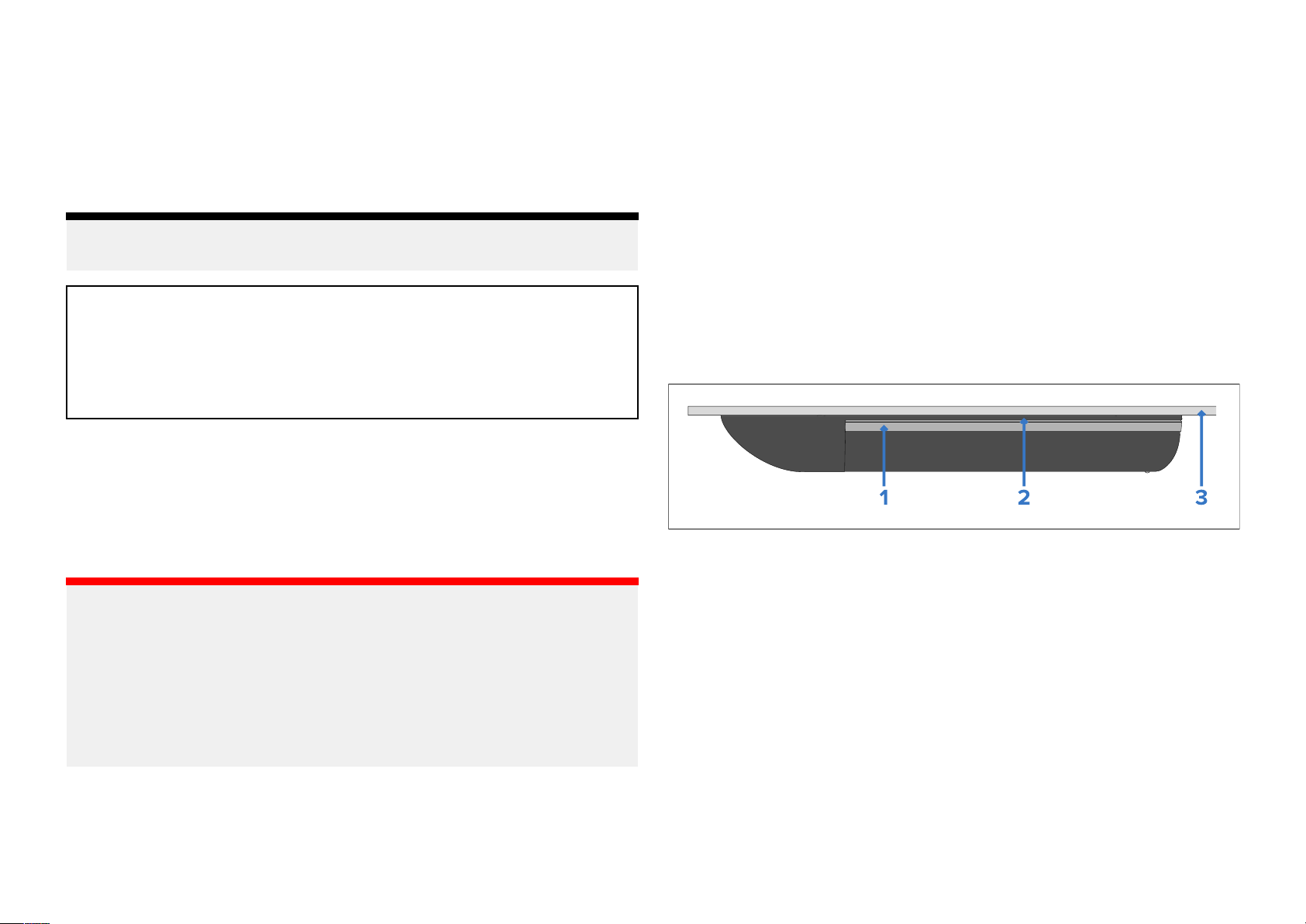
11.3Bridgingmaterialremoval
Onmetalhulledvessels,topreventgalvaniccorrosion,themetalpartsofyour
stainlesssteeltransducermustNOTtouchthehull.Theincludedhighspeed
noseconeandisolationpartsensureagapexistsbetweenthetwosurfaces.
Whencleaningyourtransducer,particularattentionmustbegiventothe
edgeofthehighspeednosecone.Ensurethatthereisnogrowthor
materialattachedthatbridgesthegapbetweenthemetalpartofthe
transducerandametalhull.
1.Metalpartoftransducer.
2.Highspeednosecone.
3.Metalhull.
11.4Re-applyinganti-foulingpaint
Ifyouhaveappliedanti-foulingpainttoyourtransducer,itisimportantto
re-applyitatleastevery6months,tomaintaineffectiveness.
Followtheinstructionsbelowtore-applyanti-foulingpaint.
Followtheguidancebelowtocleangrowthfromyourtransducer:
•Useasoftclothandamildhouseholdcleaningdetergenttocleanmild
growthbuildup .
Maintenance45
Page 46

Important:
•Followingenvironmentalbestpractice
,preparationandre-application
oftheanti-foulingpaintshouldbeperformedusingsuitablewashdown
facilities,whichensurespaintparticlesdonotenterthewaterandimpact
aquaticlife.
•Takecarenottoscratchthetransducerface,asthismayimpact
transducerperformance.
emoveyourvesselfromthewater.
1.R
2.Cleanyourtransducer ,ensuringallorganicgrowthisremoved.
3.Removeanyflakinganti-foulpaint.
4.Useasoftdryclothtoremoveanyloosebitsofpaint.
5.Re-applyawater-basedanti-foulingpaint.
46
Page 47

CHAPTER12:TECHNIC
CHAPTERCONTENTS
ALSUPPORT
•12.
1Raymarineproductsupportandservicing—page48
•12.2Learningresources—page49
T echnicalsupport
47
Page 48

12.
1Raymarineproductsupportandservicing
Raymarineprovidesacomprehensiveproductsupportservice,aswellas
warranty,service,andrepairs.Y oucanaccesstheseservicesthroughthe
Raymarinewebsite,telephone,ande-mail.
Productinformation
Ifyouneedtorequestserviceorsupport,pleasehavethefollowing
informationtohand:
•Productname
•Productidentity.
•Serialnumber.
•Softwareapplicationversion.
•Systemdiagrams.
Y oucanobtainthisproductinformationusingdiagnosticpagesofthe
connecteddisplay.
Servicingandwarranty
R aymarineoffersdedicatedservicedepartmentsforwarranty,service,and
repairs.
Don’tforgettovisittheRaymarinewebsitetoregisteryourproduct
forextendedwarrantybenefits:https://www.raymarine.com/en-
us/support/product-registration
UnitedKingdom(UK),EMEA,andAsiaPacific:
•E-Mail:[email protected]
•Tel:+44(0)1329246932
UnitedStates(US):
•E-Mail:rm-usrepair@flir.com
•Tel:+1(603)3247900
Websupport
Pleasevisitthe“Support”areaoftheR aymarinewebsitefor:
•ManualsandDocuments—http://www.raymarine.com/manuals
•Technicalsupportforum—https://raymarine.custhelp.com/app/home
•Softwareupdates—http://www.raymarine.com/software
Worldwidesupport
UnitedKingdom(UK),EMEA,andAsiaP acific:
48
.
•Helpdesk:https://raymarine.custhelp.com/app/home
•Tel:+44(0)1329246777
UnitedStates(US):
•Helpdesk:https://raymarine.custhelp.com/app/home
•Tel:+1(603)3247900(Toll-free:+8005395539)
AustraliaandNewZealand(Raymarinesubsidiary):
•E-Mail:[email protected]
•Tel:+61289770300
France(Raymarinesubsidiary):
•E-Mail:[email protected]
•Tel:+33(0)146497230
Germany(Raymarinesubsidiary):
•E-Mail:[email protected]
•Tel:+49402378080
Italy(Raymarinesubsidiary):
•E-Mail:[email protected]
•Tel:+390299451001
Spain(AuthorizedRaymarinedistributor):
•E-Mail:[email protected]
•Tel:+34962965102
Netherlands(Raymarinesubsidiary):
•E-Mail:[email protected]
•Tel:+31(0)263614905
Sweden(Raymarinesubsidiary):
•E-Mail:[email protected]
•Tel:+46(0)317633670
Finland(Raymarinesubsidiary):
•E-Mail:support.fi@raymarine.com
•Tel:+358(0)207619937
Norway(Raymarinesubsidiary):
•E-Mail:[email protected]
Page 49

el:+4769264600
•T
Denmark(Raymarinesubsidiary):
•E-Mail:[email protected]
•Tel:+4543716464
Russia(AuthorizedRaymarinedistributor):
•E-Mail:[email protected]
•Tel:+74957880508
12.2Learningresources
Raymarinehasproducedarangeoflearningresourcestohelpyougetthe
mostoutofyourproducts.
Videotutorials
RaymarineofficialchannelonY ouTube
•http://www.youtube.com/user/RaymarineInc
Trainingcourses
Raymarineregularlyrunsarangeofin-depthtrainingcoursestohelpyou
makethemostofyourproducts.VisittheTrainingsectionoftheRaymarine
websiteformoreinformation:
•http://www.raymarine.co.uk/view/?id=2372
Technicalsupportforum
Y oucanusetheT echnicalsupportforumtoaskatechnicalquestionabout
aRaymarineproductortofindouthowothercustomersareusingtheir
Raymarineequipment.Theresourceisregularlyupdatedwithcontributions
fromRaymarinecustomersandstaff:
•https://raymarine.custhelp.com/app/home
T echnicalsupport
49
Page 50

CHAPTER13:TECHNIC
CHAPTERCONTENTS
ALSPECIFICATION
•13.
•13.2Environmentalspecification—page51
•13.3RealVision™Max3Dsonarspecification—page51
•13.4Conformancespecification—page52
1Physicalspecification—page51
50
Page 51

13.
1Physicalspecification
13.3R
ealVision™Max3Dsonarspecification
Specification
Dimensions:
Cablelength:
Weight:
13.2Environmentalspecification
Specification
Operatingtemperaturerange:
S toragetemperaturerange:
Waterproofrating:
ength:424.69mm(16.72in)—includinghighspeed
•L
nosecone
•Height:223. 70mm(8.81in.)—includingcablebend
radius
•Width:79.64mm(3.14in)—includinghighspeed
nosecone
•R VM-400:8m(26.2ft)
•RVM-412/RVM-420:2m(6.5ft)+8m(26.2ft)
extensioncable=10m(32.8ft)
•RVM-400:4.56kg(includingcable)
•RVM-412/RVM-420:3.87kg(includingcable)
–2ºC(28.4ºF)to+55ºC(131ºF)
–20ºC(23ºF)to+70ºC(158ºF)
•IPx6(surfacesexteriortohull,
only)
•IPx7
•IPx8
ThefollowingspecificationonlyappliestoRealVision™Max3Dproducts.
Specification
Sonarchannels:
(Outputpower
esponsive
/R
FrequencyRange)
Sensors:
•RealVision™Max3D(70W/350kHz±30%)
•SideVision™(70W/350kHz±30%)
•DownVision™(35W/350kHz±30%)
•ConicalCHIRP:High(600W/200kHz±10%)
•Temperaturesensor
•AHRS(AttitudeandHeadingReferenceSystem)
sensor
Sonarrange
Thesonarrangeistheeffectivedepthordistancethatthetransducercan
operateto
ThefollowingrangesapplytoRealVision™Max3Dsonarchannels:
Note:
Thelistedsonarchannelrangesareindicativeonly,andmaydiffer
dependingonthetransducerinuse,theinstallation,andtheprevailing
waterconditions.
Sonarchannel
CHIRPsonar:
DownVision™:
,inoptimumweatherconditions.
Range
0.6m(2ft)to366m(1,200ft)
0.6m(2ft)to183m(600ft)
SideVision™:
RealVision™Max3D:
T echnicalspecification
0.6m(2ft)to91m(300ft)
0.6m(2ft)to91m(300ft)
51
Page 52

13.4Conformancespecification
Specification
S
tandards:•EN60945:2002
•IEC28846:1993
•EMCDirective2014/30/EU
•AustraliaandNewZealand:C-Tick,Compliance
Level2
52
Page 53

CHAPTER14:SP
CHAPTERCONTENTS
ARESANDACCESSORIES
•14.
1Spares—page54
•14.2Accessories—page54
Sparesandaccessories
53
Page 54

1Spares
14.
Thefollowingsparesareavailableforyourproduct.
•R70615—RealVision™25–pinlockingcollarkit(Includes:2xSplitrings
(includesspare),1xO-ring,1xLockingcollarand1xSplitringfittingtool).
•R70867—RealVision™RVM-4xxmountingkit(Includes:Hullnut,Cable
protector,Largeinternalisolatorsleeve,Rubberwasher,Externalisolator
plate,Highspeednosecone,2xanti-rotationstuds,2xNutsfor
anti-rotationstuds,2xSmallwashersforAnti-rotationstuds,2xSmall
internalisolatorsleevesand2xExternalisolatorsleeves).
14.2Accessories
Thefollowingaccessoriesareavailableforyouproduct.
•A80515—RealVision™3DTransducerright-angledadaptercable400mm
(15.7in.)
•A80475—RealVision™3DTransducerextensioncable3m(11.8ft.)
•A80476—RealVision™3DTransducerextensioncable5m(19.7ft.)
•A80477—RealVision™3DTransducerextensioncable8m(31.5ft.)
•A80478—RealVision™3DT ransducerY-cableforconnectingsplitpair
transducers.Cablelength:0.3m(0.98ft.)
54
Page 55

Page 56

Page 57

Inde
x
A
Accessories.............................................................................................54
All-in-one..................................................................................................13
Anti-fouling........................................................................................32,45
Anti-foulingpaint......................................................................................31
Applicabledocuments...............................................................................11
C
Documentation
Installationinstructions..........................................................................11
Mountingtemplate.................................................................................11
Operationinstructions.....................................................................11,40
Drillingholes............................................................................................28
E
ElectromagneticCompatibility.................................................................25
EMC,SeeElectromagneticCompatibility
Extensioncable........................................................................................18
Cable
Protection............................................................................................34
Strainrelief...........................................................................................34
Cableextension.................................................................................15,38
Cablelength............................................................................................20
Cableprotector.......................................................................................30
Cablerouting...........................................................................................36
Cables
Splitpair................................................................................................17
Calibration
RealVision™..........................................................................................40
CHIRP
RealVision™Max3Doverview...............................................................14
Cleaningthetransducer..........................................................................45
Compatibledisplays.................................................................................14
Compatiblesonarmodules......................................................................14
Connection
Extensioncables..................................................................................37
RVM-400..............................................................................................37
RVM-412...............................................................................................37
RVM-420..............................................................................................37
Ycable.................................................................................................37
Connections
Generalcablingguidance....................................................................34
Contactdetails.........................................................................................48
H
Hullnut....................................................................................................30
I
Installation
Testing.................................................................................................27
Toolsrequired.....................................................................................27
L
LightHouse4.............................................................................................11
Locationrequirements............................................................................23
Lockingcollarkit......................................................................................17
M
Maintenance........................................................................................7,45
Marine-gradesealant..............................................................................29
Mounting.................................................................................................30
Drillingholes........................................................................................28
N
Nutsizes..................................................................................................20
D
Deadrise...................................................................................................13
Dimensions..............................................................................................20
O
Operationinstructions.........................................................................11,40
Page 58

P
artssupplied...........................................................................................17
P
Productrecycling(WEEE)..........................................................................9
Productsupport.......................................................................................48
R
RealVision™Max3Dtransducer................................................................13
Routinechecks........................................................................................45
S
ServiceCenter.........................................................................................48
Servicing....................................................................................................7
Sonarmodules.........................................................................................14
Sonarrange.........................................................................................14,51
Spares.....................................................................................................54
Split-pair...................................................................................................13
Supportforum.........................................................................................49
T
Technicalspecification............................................................................50
Environmental.......................................................................................51
TechnicalSpecification
Conformance.......................................................................................52
Physical.................................................................................................51
RealVisionMax.....................................................................................51
Technicalsupport..............................................................................48–49
Temperaturerange..................................................................................51
Toolsrequired.........................................................................................27
Trainingcourses......................................................................................49
Transducercablelength.....................................................................17,20
Transducerlocation.................................................................................23
Transducermounting..............................................................................28
Transducerorientation............................................................................24
Troubleshooting......................................................................................40
Sonar....................................................................................................41
WEEEDirective..........................................................................................9
Y
Y-cable.....................................................................................................18
W
Warranty..............................................................................................8,48
Page 59

Page 60
Raymarine (UK / EU)
Marine House, Cartwright Drive,
Fareham, Hampshire.
PO15 5RJ.
United Kingdom.
Tel: (+44) (0)1329 246 700
www.raymarine.co.uk
Raymarine (US)
110 Lowell Road,
Hudson, NH 03051.
United States of America.
Tel: (+1) 603-324-7900
www.raymarine.com
 Loading...