

Page 1
™
REALVISION
HIGH SPEED Nose Cone
Installation instructions
English (en-US)
10-2021Date:
87419 (Rev 2)Document number:
© 2021 Raymarine UK Limited
3D
Page 2

Page 3
Productoverview
ealVision™thru-hulltransducerHighspeednosecone(Partnumber:A80702)hasbeen
TheR
designedtoimprovetheperformanceoftheRealVision™3Drangeofsonartransducers.
TheHighspeednoseconeshouldbeusedaspartoftheinitialtransducerinstallation.
Important:
•Thedocumentationsuppliedwithyourtransducershouldbereadinconjunctionwiththis
document,priortoattemptinginstallation.
•The“T
proceduredetailedinthedocumentationsuppliedwithyourtransducer.
•RetrofittingtheHighspeednoseconeonexistingRV-2xxandRV-3xxseriestransducer
installationsrequirestheholefortheanti-rotationbolttobeenlarged,to16mm(5/8inch).
•ThepartssuppliedintheHighspeednoseconeareincludedasstandardonlywithRV-4xx
seriestransducersshippedin2021onwards.ForallotherRVthru-hulltransducers,thenose
conemustbepurchasedseparately,asaccessoryA80702.
ransducermounting”proceduredetailedinthisdocumentsupersedestheinstallation
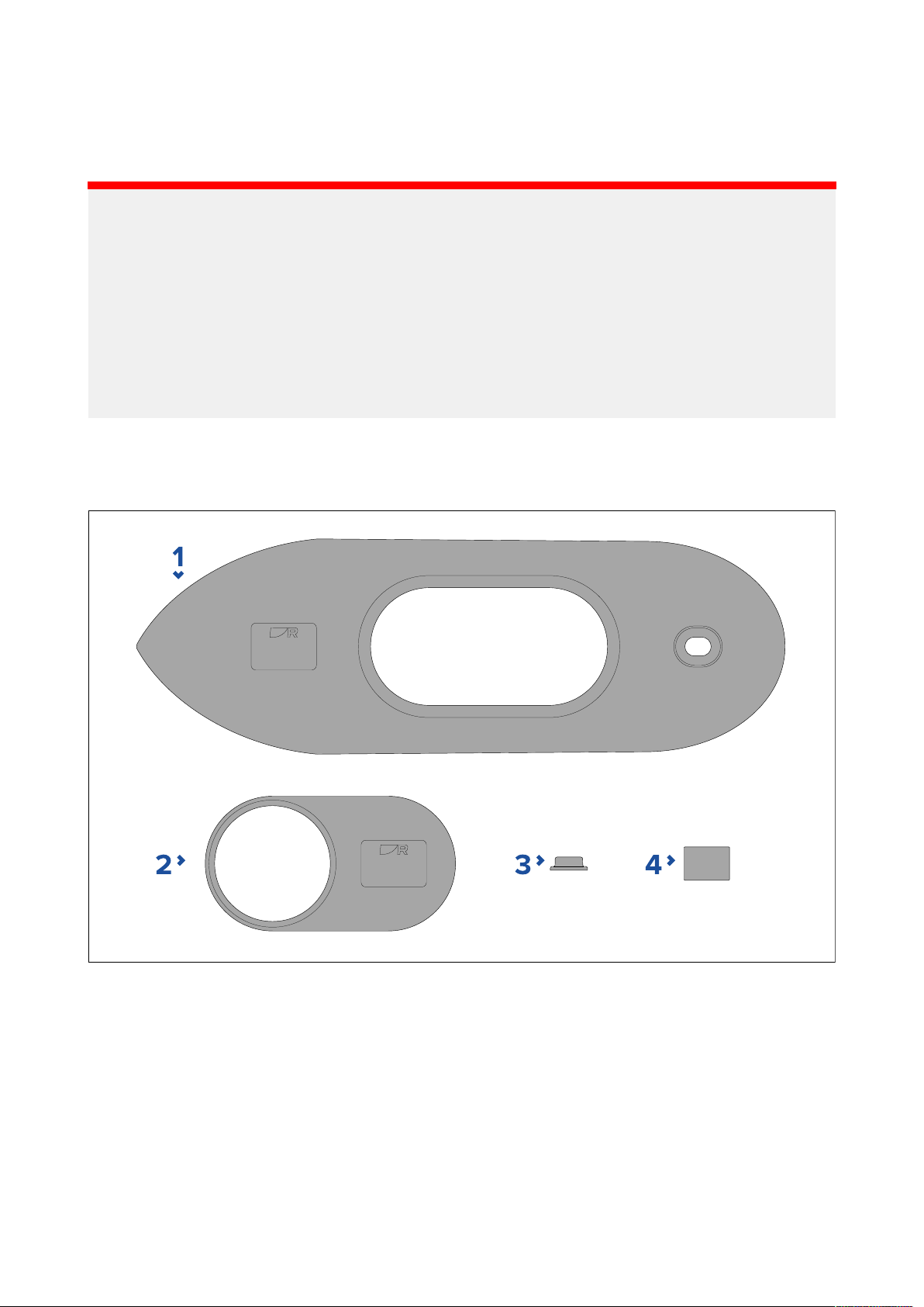
P artssupplied
ThefollowingpartsareincludedintheHighspeednoseconekit:
1.Highspeednosecone
2.Externalisolatorplate
3.Externalisolatorsleeve
4.Smallinternalisolatorsleeve
.
3
Page 4
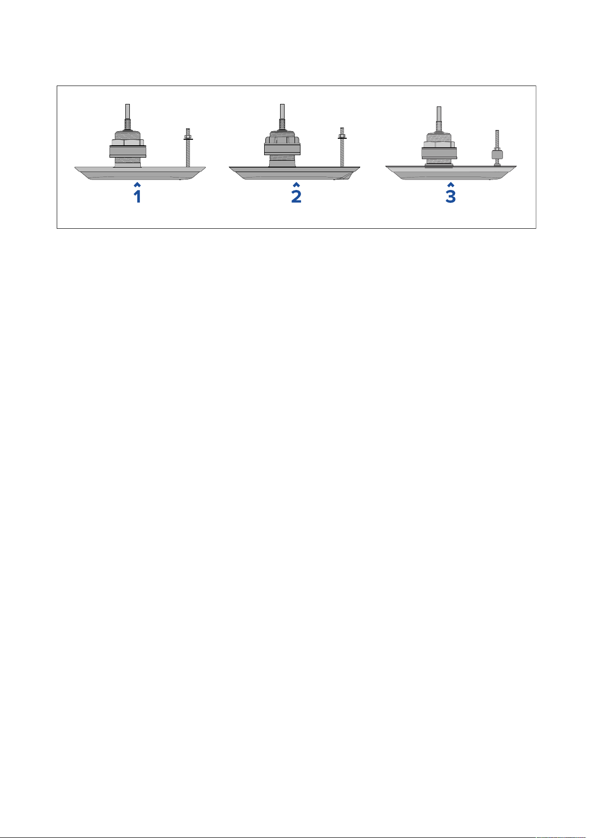
CompatibleT
TheHighspeednoseconecanbeusedwiththefollowingtransducers:
1.R V-2xx:
•RV-200RealVision™3Dbronze0°thru-hullall-in-onetransducer(Partnumber:A80465)
•RV-212PandRV-212SRealVision™3Dbronze12°thru-hullsplit-pairtransducers(System
packpartnumber:T70318)
–RV-212Pporttransducer(Partnumber:A80466)
–RV-212Sstarboardtransducer(Partnumber:A80467)
ransducers
•RV-220PandRV-220SRealVision™3Dbronze20°thru-hullsplit-pairtransducers(System
packpartnumber:T70319)
–RV-220Pporttransducer(Partnumber:A80468)
–RV-220Sstarboardtransducer(Partnumber:A80469)
2.RV-3xx:
•RV-300RealVision™3Dplastic0°thru-hullall-in-onetransducer(Partnumber:A80470)
•RV-312PandRV-312SRealVision™3Dplastic12°thru-hullsplit-pairtransducers(Systempack
partnumber:T70320)
–RV-312Pporttransducer(Partnumber:A80471)
–RV-312Sstarboardtransducer(Partnumber:A80472)
•RV-320PandRV-320SRealVision™3Dplastic20°thru-hullsplit-pairtransducers(System
packpartnumber:T70321)
–RV-320Pporttransducer(Partnumber:A80473)
–RV-320Sstarboardtransducer(Partnumber:A80474)
3.RV-4xx:
•RV-400RealVision™3Dstainlesssteel0°thru-hullall-in-onetransducer(Partnumber:A80615)
•RV-412PandRV-412SRealVision™3Dstainlesssteel12°thru-hullsplit-pairtransducers
(Systempackpartnumber:T70450)
–RV-412Pporttransducer(Partnumber:A80616)
–RV-412Sstarboardtransducer(Partnumber:A80617)
•RV-420PandRV-420SRealVision™3Dstainlesssteel20°thru-hullsplit-pairtransducer
(Systempackpartnumber:T70451)
–RV-420Pporttransducer(Partnumber:A80618)
–RV-420Sstarboardtransducer(Partnumber:A80619)
4
Page 5

ransducermounting
T
Themountingprocedurebelowshouldbereadthoroughlybeforeattemptingtomountthe
transducer.
Important:
•TheR
•DoNOTinstallstainlesssteeltransducersonvesselswithapositivegroundsystem.
Important:
•Onlyperformtheinstallationwithyourvesseloutofthewater .
•DoNOTliftorsuspendthetransducerusingitscable.
•Ensurethatthetransducerbodyissupportedduringinstallation.
•DoNOTremovethelabelattachedtothetransducercable;asithelpstoensurecorrect
•DoNOTovertightenthehullnutoranti-rotationbolt.Overtighteningcancausedamagetothe
V-4xxseriestransducersarerecommendedforvesselswithmetalhulls.Wheninstalling,
ensurethatthetransducerisisolatedfromthemetalhullusingALLofthesuppliedisolatorparts.
connection.
hullwhichmayresultinwaterleakingintothevessel.
Drillingholesinthehull
T oinstallaThru-hulltransduceryoumustdrillholesinthehullofyourvesselforthetransducer
stemandanti-rotationbolt.
1.Ensurethatyouareusingthecorrecttransducer(i.e.:port/starboard,0°,12°or20°tiltedelement)
foryourchosenmountinglocation.
2.Usingself-adhesivetape,attachthesuppliedmountingtemplatetoyourchosenmounting
location.Ensurethatthe‘Bow’arrowonthetemplateispointedtowardsthevessel’sbowand
thatthetemplateisflatandnotcreased.
3.Marktheholecentersforthetransducerstemandanti-rotationboltholesonthehullbypiercing
throughthetemplateandusingapencilormarker.
4.Removethetemplatefromthehull.
5.Drillapilotholeforthetransducerstemhole.
6.Drilla70mm(2
3
/4inch)holeforthetransducerstem,usingaholecutter.
(1)
Important:
(1)Ifthespecifiedsizeholecutterisnotavailable ,useaslightlysmallersizeholecutterandthen
carefullyfiletheholetothecorrectsize.Alternativelyyoucoulduseajigsawtocuttheholeand
thencarefullyfiletheedgetocreateacircletherequiredsize.
7 .Usingahalfroundfileand/orsandpaper,ensuretherearenoroughedgesorburrsaround
thetransducerstemhole.
8.Guidethetransducercableandthenthetransducerstemupthroughthetransducerstemhole
andsupportfrombeneath.
9.Ensurethattheanti-rotationboltholeislinedupwiththemarkyoumadeonthehullandthatthe
transducerisparalleltothecenterlineofthevessel.
5
Page 6
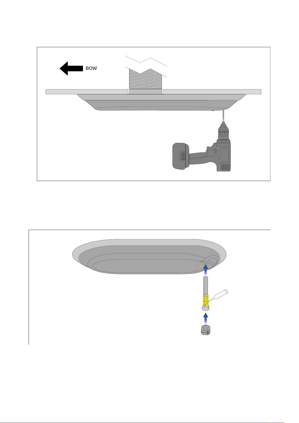
.Holdingthetransducerinplace,carefullydrillthepilotholefortheanti-rotationbolt(usingthe
10
anti-rotationholeinthetransducerasaguide).
Drillinganti-rotationbolthole
11.R emovethetransducerfromthehull.
12.Drilla16mm(5/8inch)holefortheanti-rotationbolt.
13.Checkthattheanti–rotationboltfitsthroughthehole.
Fittingtheanti-rotationbolt
Theanti-rotationboltandboltcapshouldbefittedasdetailedbelow.
1.Wipetheanti-rotationboltwithanappropriateclothandcleaningagent(fore xample:isopropyl
alcohol),andensurethesurfacesaredry,cleanandfreefromdebris.
2.Applyathickbeadofmarine-gradesealantaroundthestemoftheanti-rotationbolt,nearthe
headofthebolt.
3.Guidetheanti-rotationboltthroughtheholeinthetransducerensuringthattheboltheadis
properlyseated.
Theanti-rotationboltholeincludesacaptivenutcutouttopreventtheboltfromturningduring
tightening.
6
Page 7
4.Applyasmallamountofmarinegradesealanttotheinsideoftheanti-rotationboltcap
5.Fittheanti-rotationboltcapbypressingitfirmlyintotheholeinthetransducer .
Theembossed“BOW”arrowmustbepointingtowardsthetemperaturesensorinthebaseof
thetransducer .
Fittingthetransducer
Followthestepsbelowtofitthetransducertoyourhull.
Note:
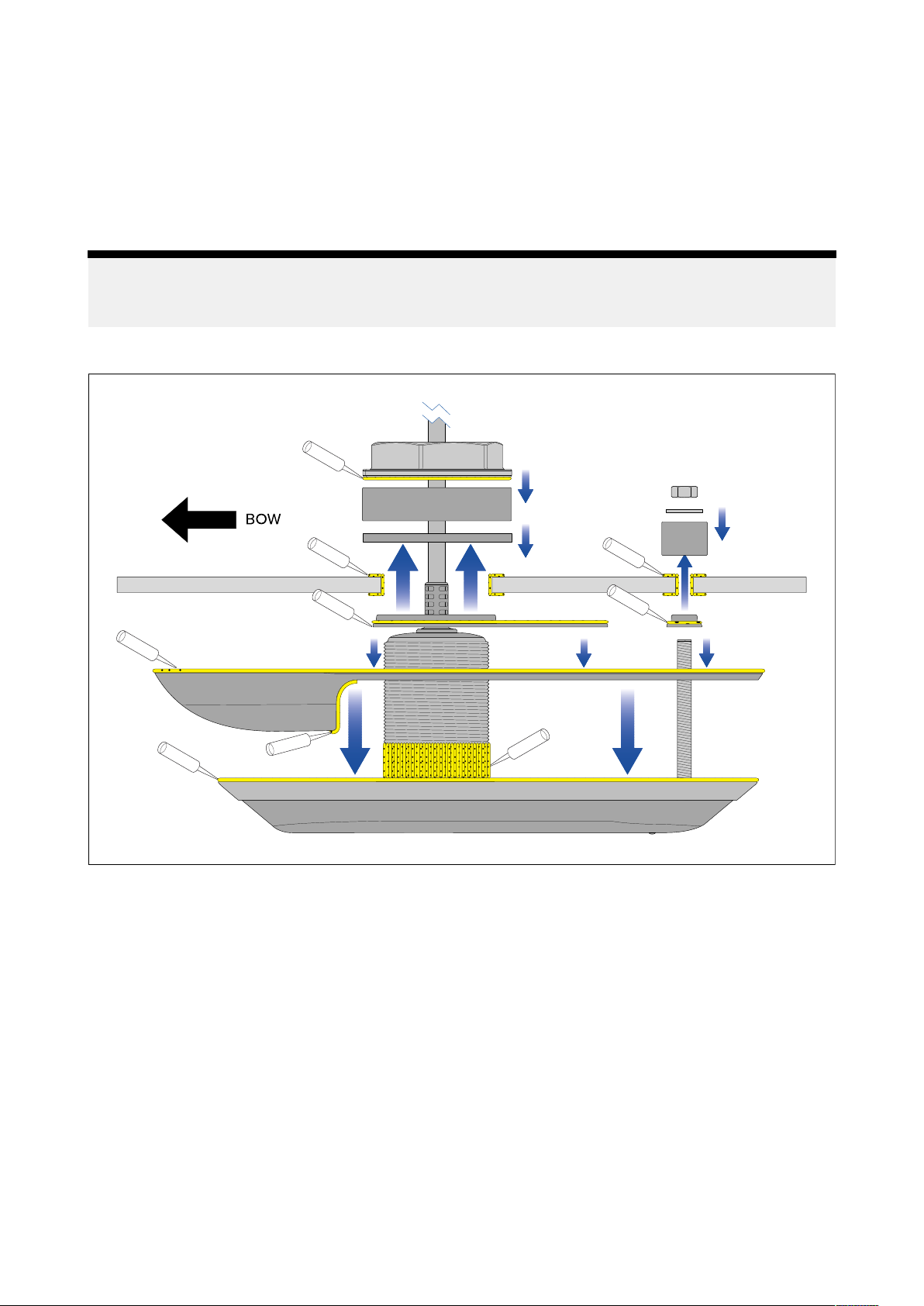
Ensurethatagenerousamountofmarine-gradesealantisusedonallmatingpartsandthatthe
partsarecleananddrybeforeinstallation,toensurealonglastingwatertightsealisachieved.
Mountingandsealantapplication
.
1.Carefullyremovealllabelsfromthetopfaceofthetransducer .
2.Removethelabelsfromthetopfaceofthetransducer,includinganyresiduallabelglue.
3.Usinganappropriateclothandcleaningagent(forexample:isopropylalcohol),wipecleanALL
surfacesofthesuppliedcomponentsandthemountinglocation,bothoutsideandinsidethehull
ensuringthattheyarefreefromgreaseanddebris.
4.Applyathickbeadofmarine-gradesealantalloverthetopfaceofthetransducersothatitis
completelycovered.
5.FeedthetransducercablethroughthestemholeintheHighspeednosecone,positioningthe
Highspeednoseconeoverthetransducer,andthenslidethetransducerintothenose.
6.ApplypressuretotheHighspeednosecone,tocompressthesealantagainstthetransducer.
7.Feedthetransducercablethroughthestemholeintheexternalisolatorplate,andthenposition
theexternalisolatorplateintherecessinthetopoftheHighspeednosecone.
8.Feedtheexternalisolatorsleeveovertheanti-rotationbolt,positioningtheexternalisolator
sleeveintheanti-rotationholerecessinthetopoftheHighspeednosecone.
9.Applyathickbeadofmarine-gradesealant:
i.alloverthetopfaceoftheHighspeednosecone,externalisolatorplate,andexternalisolator
sleeve,ensuringthattheyarecompletelycovered.
7
Page 8
ii.allaroundthebottompartofthethreadedsectionofthetransducerstemandtheprotruding
anti-rotationbolt,ensuringthatthesealantwillprotrudeappro
ximately6mm(0.24in)above
thefinaltightenednuts.
iii.allaroundandinsidethetransducerstemandanti-rotationholesontheexteriorofthehull.
10.Guidethetransducercablethroughthestemholeinthehull.
11.Guidethetransducerstemandanti-rotationboltupthroughtheholesinthevessel’shulland
supportfrombeneath.
12.Frominsidethevessel,applyacontinuous,thickbeadofmarine-gradesealantallaroundthe
baseoftheprotrudingtransducerstemandanti-rotationboltthreads.
13.Guidetherubberwasherdownthetransducercable,andoverthethreadedsectionofthe
transducerstem,ensuringthattherubberwashersitsflushonthehull.
14.Ifnecessary,applyadditionalmarine-gradesealanttothetransducerstem,abovetherubber
washer.
15.Withthetopfacepointingupwards,guidethelargeisolatorbushdownthetransducercableand
overthetransducerstem,ensuringitsitsflushontherubberwasher.
Large
Large Large
isolator
isolator isolator
bush
top
bush bush
face
top top
face face
16.Ifnecessary ,applyadditionalmarine-gradesealanttothetransducerstem,abovethelarge
isolatorbush.
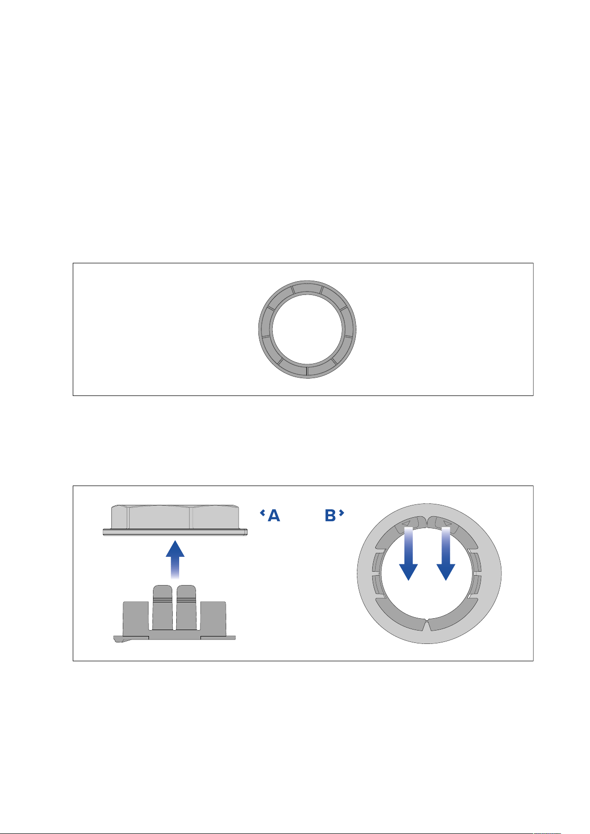
17.Ensuringthecableprotectorisfittedtothehullnut,guidethenutdownthetransducercable,
restingthenutontopofthetransducerstem.
Cable
Cable Cable
protector
protector protector
fitting
fitting fitting
and
removal
and and
removal removal
•A AA—Fitting
•B BB—Removal
18.Removethecableprotectorbypullingthe2tabsawayfromthebackofthehullnut.
19.Applyathickbeadofmarinegradesealanttothebottomfaceofthehullnut.
20.Screwthehullnutontothetransducerstemandfullytighten,usingasuitably-sizedwrench
(spanner).
Ensurethatthehullnutisadequatelytightened.Y oushouldseethesealantprotrudingfrom
theedgesofallappliedsurfaces.
8
Page 9
21.Placethesmallinternalisolatorsleeveovertheanti-rotationbolt,ensuringitsitsflushonthe
interiorofthehull.
22.Ifnecessary
,applyadditionalmarine-gradesealanttotheanti-rotationbolt,abovethesmall
internalisolatorsleeve.
23.Placethesmallwasherovertheanti-rotationbolt.
24.Ifnecessary,applyadditionalmarine-gradesealanttotheanti-rotationboltabovethesmall
washer.
25.Screwtheanti-rotationnutontotheboltandfullytighten,usingasuitably-sizedwrench(spanner).
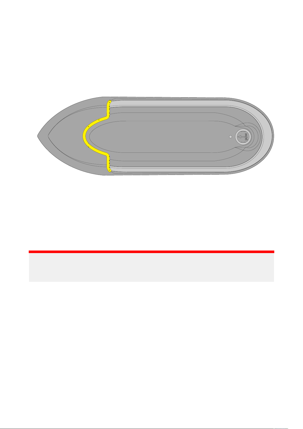
26.Applyathickbeadofmarine-gradesealantinthegapbetweenthetransducerandHighspeed
noseconeonthebottomandbothsides,asshownbelow.
27 .Removeanyexcesssealantontheoutsideofthehullandtransducer,ensuringasmooth
transitionbetweenHighspeednoseconeandtransducer,andtransducerandhull.
28.Ensurethatthemarine-gradesealanthasfullycured
Refertothesealantmanufacturer’sinstructionsforcuringtimes.
29.Unlesslocalenvironmentalregulationsprohibit,applyawater-basedanti-foulingpainttothe
bottomfaceofthetransducer ,ensuringalloftheexternallyexposedtransducersurfacesare
coatedandthepaintoverlapsontothehull.
30.Checkforleaksaroundthetransducerimmediatelyuponputtingthevesselbackinthewater.
Important:
DoNO Tleaveyourvesselinthewateruncheckedafterinstallingyourtransducer.Verysmallleaks
maynotbeimmediatelyobvious,andaconsiderablevolumeofbilgewatercouldaccumulate
overthecourseofaday,orovernight.
31.Checkforleak satregularintervalsafterinstallation,untilyouaresatisfiedthattherearenoleaks.
32.Addaregularcheckforleaksaroundthetransducertoyourroutinevesselmaintenanceschedule.
9
Page 10
Anti-fouling
Wherelocalregulationsallow
anti-foulingpaint.Thiswillhelppreventthebuild-upofbarnaclesandotherorganicgrowth,which
cancauseincreaseddragthatwilldegradesonarperformance.
Important:
•Beforeapplyingwater-basedanti-foulingpaint,checkthatlocalenvironmentalrulesand
regulationsdonotprohibittheuseofanti-foulingpaint.
•Neverusecopper-basedanti-foulingpaintasthiscanimpacttransducerperformance
•Neveruseketone-basedanti-foulingpaintasthiscanattackthetransducer’splastic,damaging
thetransducer .
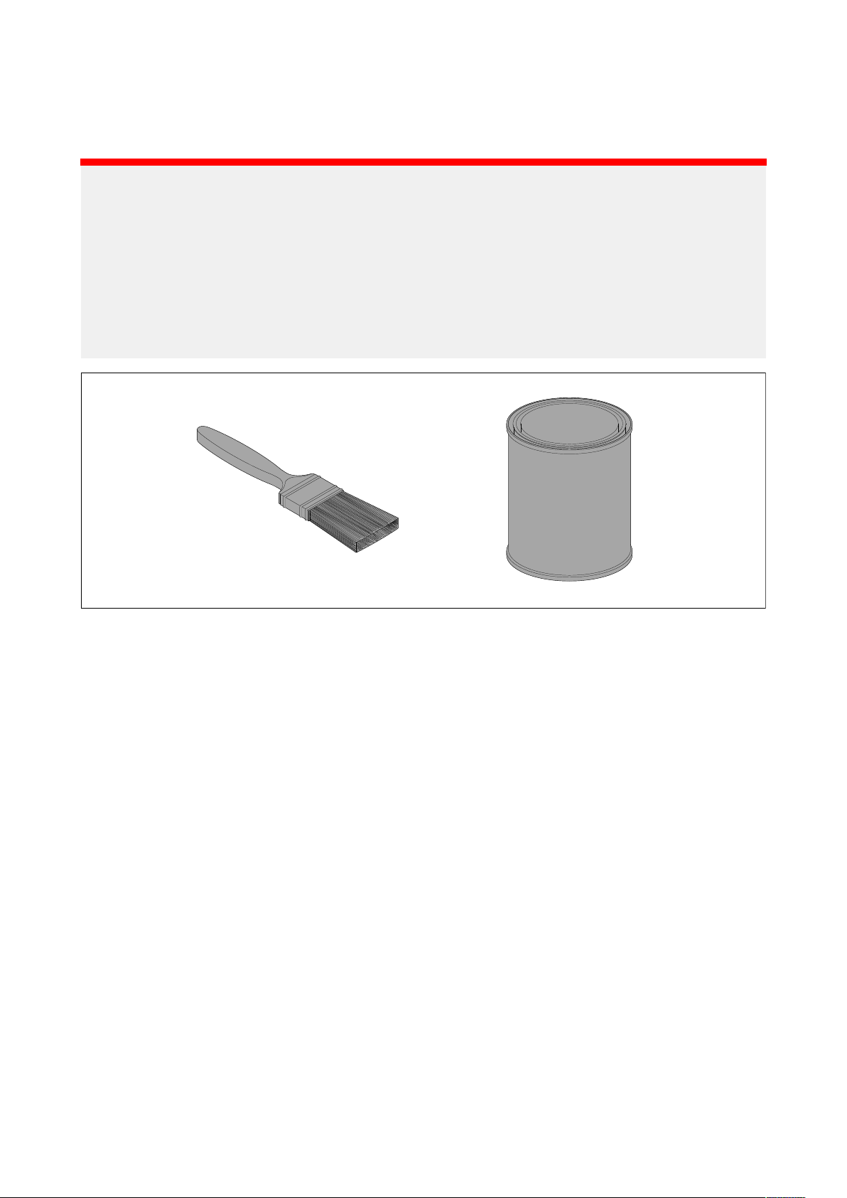
•Paintyourtransducerusingabrush,donotuseaspraycanoraspongerollerasthesemethods
cancausetinyairbubblestobeincorporatedinthepaint,whichwillalsoreducetransducer
performance.
,itisrecommendedthatyoucoatyourtransducerusingawater-based
.
Theanti-foulingpaintshouldbeappliedinathinandevencoatcoveringalle xternallyexposed
transducersurfaces.
Y oushouldcleanyourtransducerregularlyandre-applyanti-foulingpaintevery6months,orsooner
dependingonhowrapidlyorganicgrowthbuildsup.
10
Page 11
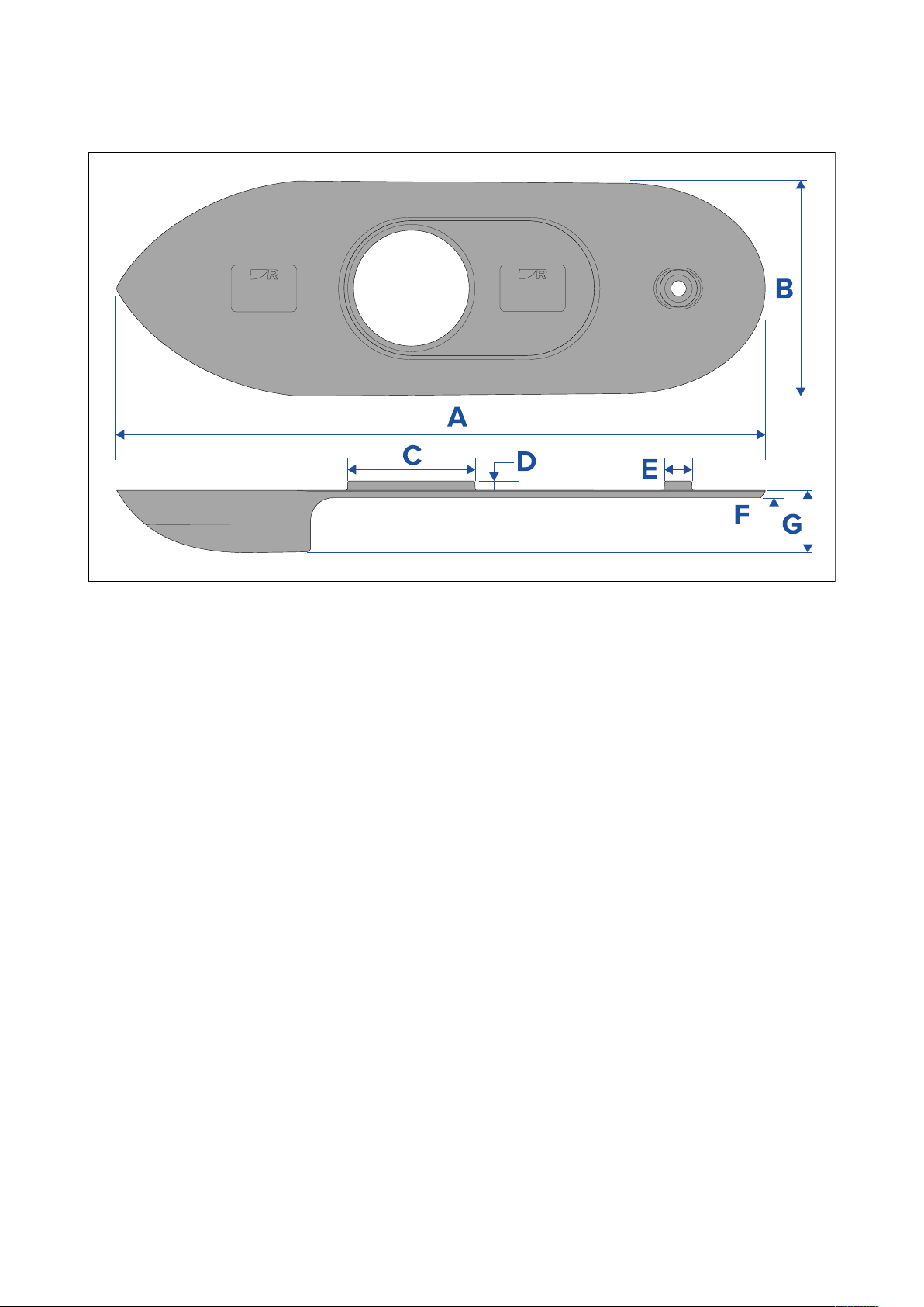
Highspeednoseconedimensions
TheHighspeednoseconewillaffecttheoverallsizeofthetransducer
arearequiredforthemountinglocationandthesizeoftheholesthatarerequiredinthehull.
,andthereforeimpactthe
•A=347 .51mm(13.68in)
•B=114.00mm(4.49in)
•C=68.00mm(2.68in)
•D=2.00mm(0.08in)
•E=14.90mm(0.59in)
•F=4.00mm(0. 16in)
•G=33.46mm(1.32in)
11
Page 12

Page 13

Page 14
Marine House, Cartwright Drive, Fareham, Hampshire.
Raymarine
PO15 5RJ. United Kingdom.
Tel: +44 (0)1329 246 700
www.raymarine.com
a brand by
 Loading...