

Page 1

A65 and RS12
Chartplotter & GPS
Installation Manual
Document number: 87055-2
Date: March 2006
Page 2

Tr ademarks and registered trademarks
Raymarine is a registered trademark of Raymari ne plc.
Navionics is a registered trademark of Navionics Company , Italy.
All other product names are trademarks or registered trademarks of their
respective owners.
Contents of this handbook © Raymarine 2006
Page 3

3
Contents
Important Information .................................. .................................. .....................5
Chapter 1: Introduction ............................. .................................. ........................9
1.1 Selecting the Display Unit Location .................. ................................ ......9
1.2 What Comes in the Box ........................................................................10
1.3 Optional Equipment ............................................................................11
1.4 Unit Size ...............................................................................................12
Chapter 2: Installing the Display Unit ............................................................13
2.1 Mounting ................................... ......................... ....................... ..........13
Mounting Bracket Method .................................................................13
Flush Mounting ...................................................................................14
2.2 Cable Runs ...........................................................................................15
Making the Cable Connections ............................................................16
Power Input Cable (R08003) ...............................................................16
Power Supply .............................................................................17
NMEA Cable (R08004) ......................................................................18
GPS Cable ............................................................................................18
Chapter 3: Installing the GPS Antenna .................. ..................................... .....19
3.1 Selecting the Mounting Location .........................................................19
Receiver Location .................................................................................19
Cabling Route ......................................................................................20
3.2 Mounting the Receiver .........................................................................20
Pole Mounting ......................................................................................20
Surface Mounting ................................................................................21
Making the Cable Connections ............................................................22
Chapter 4: Maintenance ................................................... .................................23
4.1 Introduction .................................. ......................................... ..............23
Servicing and Safety .............................................................................23
Routine Checks ....................................................................................23
Cleaning the Display ............................................................................24
4.2 Resetting the System ............................................................................24
Power -on Reset ..............................................................................24
Settings Reset ................................................................................24
Settings and Data Reset .................................................................25
4.3 Troubleshooting .................................. .......................... .......................25
Common Problems and How to Solve Them .........................................26
4.4 Upgrading the Display .......................................................................27
4.5 T echnical Support .................................................................................29
Worldwide Web ...................................................................................29
Contacting Raymarine in the US ...........................................................29
Contacting Raymarine in Europe ..........................................................31
Page 4

4 A65 Installation Manual
Appendix: Specifications .................................... ... ... ... .. ... ...... ... .. ... ... ... ... ..... ... .23
A65 LCD Color Display...................................................................................33
General .................................................................................................33
Chartplotter Features ...........................................................................34
Interfacing .................................. ............. ............. ................ ............. ...34
RS12 GPS Sensor ...........................................................................................35
Index ......................................................................................................................37
Page 5
Important Information
Intended Use
The A65 is a GPS Chartplotter display unit that can be upgraded to include
optional Fishfinder functionality.
This handbook contains i mportant information on the installat ion of your A65
display and RS12 GPS Antenna. To get the best results in operation and
performance, please ta ke the time to thoroughly read the accompanyi ng Owner’s
Handbook.
Safety Notices
WARNING: Navigation Aid
This product is intended to be used as an aid to navigation. Its
accuracy can be affected by many factors, including equipment
failure or defect, environmental conditions and incorr ect
handling or use. It is the Users responsibility to exer cise common
prudence and navigational judgement. This device should not be
relied upon as a substitute for such prudence and judgement.
5
WARNING:
This equipment must be installed in accordance with the
instructions in this manual. Failure to do so could r esult in poor
product performance, personal injury and/or damage to the
vessel.
WARNING:
Make sure the power supply is switched off before making any
electrical connections.
CAUTION: Global Positioning System Antenn a
Do not connect or disconnect the GPS antenna from the display
unit while power is switched on as this may result in irrepar able
damage.
CAUTION: Water Ingress
To prevent the ingr ess of water and consequent damage to the
display , ensure that the chart card door is firmly closed. This can
be confirmed by an audible click.
Product Installation
Electrical Safety
Page 6

6 A65 Installation Manual
CAUTION: Compact Flash Card Instal lation
When installing CompactFlash cards ensure that the card is
inserted in the correct orientation. DO NOT try to force the card
into position as this may result in irreparable dama ge to the card.
CAUTION: Compact Flash Card Damage
DO NOT use a metallic instrument such as a screwdriver or pliers to
help you remove a card, as this can cause irreparable damage .
EMC Conformance
All Raymarine equipment and accessories are designed to the best industry
standards for use in the recreational marine environment.
Their design and manufacture conforms to the appropriate Electromagnetic
Compatibility (EMC) standards, but correct installation is required to ensure that
performance is not compromised. Although every effort h as been taken to ensure
that they will perform under all conditions, it is important to understand what
factors could affect the operation of the product .
The guidelines given here describe the conditions for opti mum EMC performance,
but it is recognized that it may not be possible to meet all of these conditions in all
situations. T o ensure the best possible conditions for EMC performance within the
constraints imposed by any location, always ensure the maximum separation
possible between differen t items of electrical equi pment.
For optimum EMC performance, it is recommended that wherever possible
Raymarine equipment and cables connect ed to it are:
At least 3 ft. (1 m) from any equipment transmitting or cables carrying radio
signals e.g. VHF radios, cables and antennas . In the case of SSB radios, the
distance should be increased to 7 ft. (2 m).
More than 7 ft. (2 m) from the path of a radar beam. A radar beam can normally be assumed to spread 20 degrees above and below the r adiating element.
Ensure that the equipment is supplied from a separate battery from that used for
engine start. Vo ltage drops below 10 V, and starter motor tran sients, can cause
the equipment to reset. This will not damage the equipment, but may cause the
loss of some information and may change the operating mode .
Ensure that Raymarine specified cables are used. Cutti ng and rejoining these
cables can compromise EMC performance and must be avoided unless doing so is
detailed in the installation manual.
Page 7
Important Information 7
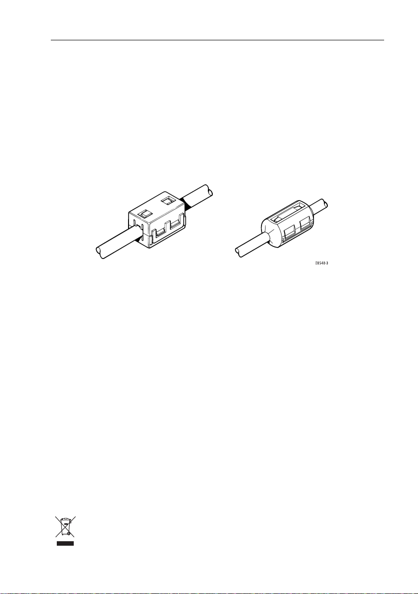
Suppression Ferrites
If a suppression ferrite is attached to a cable, this ferrite should not be removed. If
the ferrite needs to be removed during installation it must be reassembled in the
same position. If a ferrite is packed separately in the carton, it must be installed as
soon as the cables are run.
The following illustration shows typical cable suppression ferrites sometimes
used with Raymarine equipment. T o ensure EMC compliance, always use these
ferrites, if supplied by Raymarine for use with this equipment. If not supplied by
Raymarine, a ferrite is not required for use with this equipment.
D3548-3
Connections to Other Equipment
If your Raymarine equipment is to be con nected to other equipment using a cable
not supplied by Raymarine, the suppression ferrite (if supplied) MUST always be
attached to the cable nearest the Raymarine unit.
TFT LCD Displays
The colors of the display may seem to vary when viewed against a colored
background or in colored light. T his is a perfectly norm al effect that will be seen
with all color LCD displays .
In common with all Thin Film T ransistor (TFT) LCD displays, the screen may exhibit
a few (less than 5) wrongly illuminated pixels. These may appear as black pixels in
a light portion of the screen or as colored pixels in black areas.
CAUTION: To pr ovide protection against the damaging effects of
UV light, Raymarine advises that you replace the sun cover
provided when the color LCD display is not in use.
Product Disposal
When you want to dispose of t his product at the end of its working life , please do
so in accordance with local regulations .
Page 8
8 A65 Installation Manual
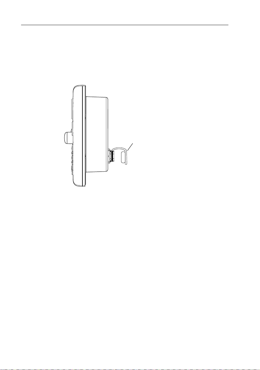
Protective Dust Covers
Protective covers have b een attached at the factory on the SONAR, AUX and
NMEA connectors on the rear of the A65. If you are not u sing one or more of these
ports, please k eep the cover attached to the connector to protect it from the
elements.
Dust Cover
D8695-1
Page 9

Chapter 1: Introduction
This manual provides information and instructions for installing your A65 display
and RS12 GPS sensor .
1.1 Selecting the Display Unit Location
Y our A65 can be mounted using the mounting bracket supplied, o r console
mounted using the optional flush mount kit.
Before you install the display, plan its installation, considering:
•
Convenience. T he mounting location should be easily accessible to allow
operation of the front panel controls .
•
Access. There must be sufficient space behind the display to allow cable con-
nections to the rear panel connectors , avoiding tight bends in the cable.
•
Interference. T he selected location should be far enough away from devices
that may cause interference , such as motors, gener ators and radio transmitters/receivers (see EMC Guidelines).
•
Magnetic compass. Mount the di splay at least 3ft (1m) aw ay from a mag-
netic compass.
•
Cable runs. T he display should be mount ed as close as possible to the DC
power source.
•
Environmental. The display should be protected from physical d amage and
excessive vibration. Although the display unit is waterproof , it is good practice
to mount it in a protected area away from prolonged and direct exposure to
rain and salt spray.
9
Page 10
10 A65 Installation Manual
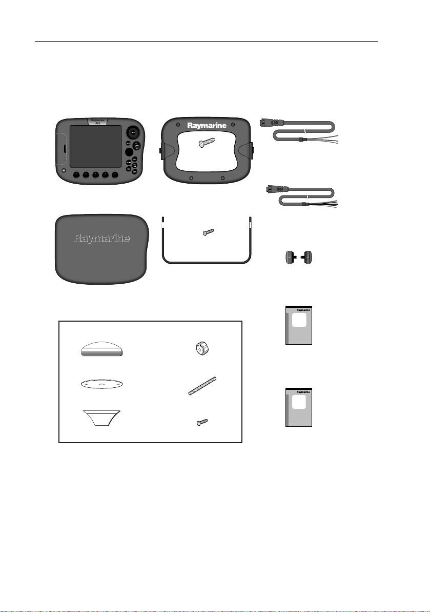
1.2 What Comes in the Box
Unpack the display carefully , to prevent damage . Save the carton and packing, in
case the unit has to be returned for service.
A65 GPS Chartplotter,
E33020 (US), E33022 (CE)
A65 Sun Cover,
part no. R38108
RS12 GPS, part no. E33021
GPS Antenna
GPS Gasket
Pole Mount Bracket
Frame Screws,
M3 (x4)
A65 Mount Frame,
part no. R38109
Bracket Screws,
No.10 x 3/4 (x3)
Mounting Bracket,
part no. R38110
Thumb nuts (x2)
Studs (x2)
Mount Screws, M4 (x2)
Power/Data Cable, 3 pin, 1.5m
part no. R08003
NMEA Cable, 5 pin, 1.5m
part no. R08004
Bracket Knobs,
part no. R38107
A65
Installation
Manual
Installation Manual,
part no. 87055
A65
Owner's
Handbook
Owner's Handbook,
part no. 81248
D7733-1
Page 11

Chapter 1: Introduction 11
1.3 Optional Equipment
The following optional items are also availabl e to complete your system:
Part No. Description
E63070 DSM25, Digital Sounder Module, 200/50KHz, 500W
E36017 Flush Mount Kit, A65
R69086 Network Cable , A65, 3.5m
E36015 Network Cable , A65, 8.5m
E36016 Network Cable , A65, 15m
E66066 T ransducer Adapter , P athfinder (DSM250) to A Series
E66070 T ransducer Adapter , Legacy T ransducer (L365/L470) to A Series
Page 12

12 A65 Installation Manual
1.4 Unit Size
The dimensions for your A65 display are as follows:
9.61in (244mm)
ENTER
PWR
2.56in
(65mm)
9.88in (251mm)
11.02in (280mm)
2.40in (61mm)
.866in (22mm)
CANCEL
ACTIVE
DATA
RANGE
PAG E
WPTS
MOB
MENU
6.81in
(173mm)
7.83in
(199mm)
D7718-1
Bracket Mount
3.11in
(79mm)
3.43in
(87mm)
Flush Mount
Page 13

Chapter 2: Installing the Display Unit
The A65 display unit is waterproof to IPX-7 and can be installed either above or
below deck using either the mounting bracket or by flush mounting into the
console.
2.1 Mounting
Note:
The mounting bracket and the mount frame to which the bracket attaches must be
removed prior to flush mounting.
Mounting Bracket Method
The mounting bracket can be used to secure the display unit to a dash, chart table,
bulkhead or deckhead.
Mount Frame
Display Unit
Frame Screws (x4)
Mounting Bracket
Bracket Knobs (x2)
13
D7898-1
Y ou should install the mount bracket as follows:
1. Loosen the knobs and remove the brack et from the unit.
2. Mark the locations of the brack et screw holes on the mounting surface .
3. Drill 9/64” (3mm) pilot holes at the mark ed locations , taking care that there
are no cables or anything that may be damaged behind the surface.
4. Align the bracket holes wit h the holes on the mounting surface .
Page 14

14 A65 Installation Manual
5. Use the screws and nuts supplied to securely attach the bracke t to the mounting surface.
1
x3
2
3
x3
6. Attach the display unit to the brack et.
7. Adjust the unit angle for clear vision and tighten the knobs.
Flush Mounting
Flush mounting your display on the console requires the optional E36017 Flush
Mount Kit.
D7899-1
D7721-1
Page 15

Chapter 2: Installing the Display Unit 15
CAUTION: Installation
Make sure there are no hidden electrical wires or other
items behind the selected location before pr oceeding.
Make sure there is sufficient rear access for mounting
AND CABLING.
1. Check the selected location for the unit. A clear, flat area with suitable clearance behind the panel, is required.
2. Attach the template included with the flush mount kit to the selected location, using masking or self-adhesive tape, taking care that it is level.
3. Use a hole saw to make a pilot hole in each corner of the cut-out area.
4. Using a suitable saw, cut along the inside edge of the cut-out line.
5. Detach the mount frame from the unit by removing the four mounting screws.
Make sure that the unit fits in the area that has been cut out.
6. Drill four 3/16 in (4.5 mm) holes as indicated on the template to accept the
retaining bolts.
7. Place the gasket onto the display unit.
8. Connect the cables to the display , avoiding tight bends .
9. Slide the unit into the console and secure using the included hardware.
2.2 Cable Runs
When installing system cables consider the following:
• All cables should be adequa tely secured, protected from physical damage and
exposure to heat. Avoid running cables through bilg es or doorways , or close
to moving or hot objects.
• Avoid acute bends .
• Where a cable passes through an exposed bu lkhead or deckhead, a wate rtight feed-through should be used.
• Secure cables in place using tie-wraps or lacing twine. Coil any extra cable
and tie it out of the w ay .
• Do not pull cables th rough a bulkhead or deckhead using a cord attached to
the connector . T his could damage the connections .
Page 16

16 A65 Installation Manual
.
RS12
A65 Display
DSM25 Sounder
GPS SONAR AUX NMEA POWER
GPS
12V Power Supply
Fluxgate Compass
Power Power
Fishfinder
NMEA
Transducer
Making the Cable Connections
The cable connections are located on the back of the display unit as shown below:
GPS SONAR AUX NMEA POWER
D7719-1
Power Input Cable (R08003)
This 1.5m (5 ft) cable is supplied for connecting to your boat’s DC power supply.
DC power is connected at the 3-pin POWER connector on the unit’s connector
panel. The connector (viewed from the outside) and pin fun ctions are shown in
the following diagram and table.
D7722-2
Page 17

Chapter 2: Installing the Display Unit 17
1
D7734-1
2
3
Power Connector
Pin No. Function Color
1 Battery positive (12 VDC systems) Red
2 Battery negative Black
3 Shield (drain wire) No insulation
Power Supply
The A65 is intended for use on boat’ s DC power systems rated from 10.7 to
18 VDC. The power connection to the unit should be made at either the output of
the battery isolator switch or at a DC power distribution panel. P ower should be
fed directly to the A65 via its own dedicated cable system and protected by a
thermal circuit breaker or fuse on t he red (positive) wire that is installed close to
the power connection.
CAUTION: Dedicated Power Connection
The A65 also supplies power for the GPS and sounder units (if so
equipped). To minimize succeptibil ity to display flickering due to
power fluctuations, provide the display unit with its own
dedicated connection to boat’s power.
The RED wire must be connected to the feed from the positive (+) battery terminal
and the BLACK wire to the feed from the negative (–) battery terminal. T he shield
wire (drain) should be connected to the boat’s RF ground.
CAUTION: Fuse Protection
Install a fast blow 4 amp fuse on the red (positive) wire.
If a longer power cable run is required, use the supplied power cable to connect to
the display unit. Then use a suitable connector block to connect the free end to the
extension cable, taking particular care to ensure the correct polarity.
Page 18

18 A65 Installation Manual
Use commonly practiced methods to determine proper wire gauge based on wire
length, current, and wire tables. Y ou may also trim the power cable supplied with
the A65 to reduce overall wire length. Only use enough wire to connect the unit to
the power source, including a service loop.
Note:
When the A65 has been powered off using the PWR key but is still electrically con-
nected to the power supply, the GPS continues to draw current.
The supplied power cable has a cross section of 10 mm.
CAUTION: Correct Polarity
If the power connections are accidentally reversed the system
will not work. Use a multimeter to ensure that the input power
leads are connected for correct polarity .
NMEA Cable (R08004)
The 5-pin, 1.5m (5 ft) NMEA input cable is supplied with exposed wire connecting
tails. T hese should be connected to your existing NMEA instruments using
suitable connector blocks as follows:
Function Color Pin no.
NMEA Input (-ve) common Green 1
NMEA Input (+ve) White 2
NMEA Output (+ve) Y ellow 3
NMEA Output (-ve) common Brown 4
Not connected Screen 5
2
1
D7735-1
3
4
5
GPS Cable
Connect the 6-pin RS12 cable to the left-most connector, labeled GPS.
Page 19

Chapter 3: Installing the GPS Antenna
The RS 12 package contains the following items:
1. Low profile GPS Receiver , with 10 m (33 ft) cable
2. Flush mount gasket
3. Mounting studs (x2) and thumb nuts (x2)
4. Pole mount kit *
Note:
* If you intend to mount the receiver on a pole, you will need to obtain a suitable
pole with 1 inch 14 TPI thread.
3.1 Selecting the Mounting Location
The RS12 can be mounted on a pole or flush mounted on a suitabl e horizontal
surface.
Receiver Location
The RS12 receiver is designed to receive the signals emitted from satellites in a
direct path. It should be mount ed:
• On a horizontal surface .
• In a location that is open and clear of any obstructions (such as masts, search
lights, or other structures) that could block line-of-sight reception of signals.
• As low as possible: the height of the receiver i s not as important as it having a
clear view horizon to horizon for optimum signal reception. In fact, the lower
the unit can be mounted and have a clear view to satellites, the better . T he
more stable the unit, the more effectively it will track satellites low to the horizon.
Note:
Do NOT mount the receiver up a mast, as the receiver will swing with the b oat,
leading to significant COG/SOG errors.
• As far as possible from any sources of interference: the receiver should be separated by at least 1 m (3 ft) from other antennas and electroni c equipment. It
should not be mounted in the direct path of a r adar’s beam.
When mounting the receiver flush to a surface:
• select an area that a llows access to the underside of the mounting surface
• avoid areas where the receiver might be stepped on or tripped over
19
Page 20

20 A65 Installation Manual
Cabling Route
When planning the location for the unit, consider the best rou te for running the
cable between the receiver and GPS display unit or to the rest of an integrated
system. Ideally , you should try to route t he cable so it is:
• hidden from view
• separated as far as possible fr om other cables (to prevent interference)
When running cable, always observe the following guidelines:
• if a cable has to be fed through the deck, use a good qualit y deck grommet
• where cables are fed through holes , use grommets to prevent chafing
• secure long cable runs so they do not present a hazard
• wherever possible , route cables away from f luorescent lights , engines and
radio transmitting equipment, as these may cause interference
3.2 Mounting the Receiver
When you have selected a suitable location, follow the installation instructions
for
Pole Mounting
Pole Mounting
Note:
You will need to obtain a suitable pole with 1 inch 14 TPI thread.
1. Securely attach the pole mount base to a sui table pole or rail mount brack et.
2. Pass the cable through either:
A: the center hole of the pole mount base , or
B: the side exit channel
Note:
If you intend to use the side exit channel, remove the two plastic ta bs obstructing
the channel. If you do not remove these tabs befo re using the cable channel, you could
damage the cable.
3. Check the cable is positioned correctly, then secure the receiver to the pole
mount base using the two M4 screws provided.
or
Surface Mounting
.
Page 21

Chapter 3: Installing the GPS Antenna 21
.
B
A
D8689-1
Surface Mounting
1. Use the template supplied in this handboo k to mark the two 6 mm (0.25 in)
mounting holes.
2. OPTION A:
If the cable is going to pass through the mounting surface drill a 19 mm (0.75
in) center hole.
OPTION B:
If the cable is to exit from the side of the receiver above the mounting surface, remove the two plastic tabs (1) obs tructing the cable channel. If you do
not remove these tabs before using the cable channel, you could damage the
cable.
3. Screw the two mounting studs (2) into the underside of th e receiver .
4. Stick the supplied gasket (3) to the mounting surface , ensuring that the holes
on the gasket cor respond with the drilled holes .
5. Pass the cable down through the center hole (Option A) or route it through the
cable exit channel (Option B).
6. Carefully position the receiver so the mounting studs pass through the holes
in the mounting surface .
7. Secure the receiver to the surface using the two thu mb nuts (4).
Page 22

22 A65 Installation Manual
AB
1
2
4
3
2
4
Top view Underside view
Making the Cable Connections
Connect the cable to the connector Labeled GPS on the back of the display unit as
shown below:
.
RS12
A65 Display
3
D8690-1
GPS SONAR AUX NMEA POWER
D8506-1
GPS
Page 23

Chapter 4: Maintenance
4.1 Introduction
This chapter provi des information on maintainin g and troubleshooting your A65
GPS Chartplotter and on how to g et assistance from Raymarine .
At regular intervals , carry out the followin g servicing procedures:
• Routine checks .
• Cleaning the Display.
Do not attempt any other servicing procedures .
Servicing and Safety
• Raymarine equipment should be serviced only by authorized Raymarine service technicians. T hey will ensure that service procedures and any replacement parts used will not affect performance . T here are no user serviceable
parts in any Raymarine product.
• Some products generate high voltages , so never handle the cables or connectors when power is being supplied to the equipment.
• When powered on, all electrical equipm ent produces electromagnetic fields .
These can cause adjacent pieces of electrical equipment to interact with one
another , with a consequent adver se effect on operation. In order to minim ize
these effects and enable you to get the best po ssible performance from your
Raymarine equipment, guidelines are given in the installations manual, to
enable you to ensure minimum interaction between different items of equipment, i.e. ensure optimum Elec tromagnetic Compatibility (EMC).
• Always report any EMC-related problem to you r nearest Raymarine dealer .
We use such information to improve our quality standards.
• In some installations , it may not be possible to prevent the equipment from
being affected by external influences. In general this will not damage the
equipment, but it can lead to spurious re-setting action, or momentarily may
result in faulty operation.
23
Routine Checks
Carry out the following tasks on a regular basis:
• Examine all cables for signs of damage, such as chafing, cuts or nicks.
• Check that all cables are securely connected.
Page 24

24 A65 Installation Manual
Cleaning the Display
Regularly clean your Display as follows:
1. Switch off the power to the Display .
2. Wipe the Display with a clean soft cloth. T o remove oily finger ma rks use a
spray cleaning agent of the type used for cleaning eyeglasses.
Note:
Do not use acid, ammonia based or abrasive products.
4.2 Resetting the System
Y ou can reset the A65 display in one of three ways:
•Power-on Reset
• Settings Reset
• Settings and Data Reset
Power-on Reset
When you reset the system, at power -on the last used values are retained for all
the options, except for those listed in the following table which are reset to the
factory default each time:
Item Power-on setting
Relative Motion mode Relative
Brightness ON at 100%
Settings Reset
The factory reset will set all values back to their original factory settings. T he
Waypoint and Rout e List databases are not reset. T here are two ways to carry out
a Settings Reset: using hardware k eys or via the System Setup Menu.
T o carry out a Settings Reset using the hardware k eys:
1. With the A65 powered OFF, press and hold the left hand soft key .
2. Press and release the POWER key to power ON the display , but contin ue to
hold in the soft k ey . A countdown message appears . Continue to depress the
soft key until the RESETTING DA TAB ASE message appears.
The reset will tak e place during this operation.
Page 25

Chapter 4: Maintenance 25
T o carry out a Settings Reset using the System Setup Menu:
1. With the A65 powered ON, press the
2. Use the trackpad to navigate to the System Setup me nu.
3. Select Settings Reset. A confirmation message appears.
4. Press
ENTER to accept the reset or CANCEL to quit without resetting.
MENU key.
Settings and Data Reset
This option returns all settings to their original factory values and deletes all
waypoints and route lists .
T o carry out a Settings and Data Reset:
1. With the A65 powered ON, press the
2. Use the trackpad to navigate to the System Setup me nu.
3. Select Settings and Data Reset. A confirmation message appears.
4. Press
ENTER to accept the reset or CANCEL to quit without resetting.
MENU key.
4.3 Troubleshooting
All Raymarine products are, prior to packing and shipping, subjected to
comprehensive test and quality assurance programs. However , if your A65 should
develop a fault, this section will help you to identify the most likely cause and
show the corrective action required to restore normal operation.
If, after referring to this section, you are still having prob lems with your Display ,
contact your local dealer, national distributor or Raymarine Technical Services
Department for further advice.
Always quote the product serial numbers which are printed on the back of the
unit.
Page 26

26 A65 Installation Manual
Common Problems and How to Solve Them
Problem Solution
Display is blank 1. Make sure that the power supply c able is sound and
that all connections are tight and free from corrosion.
2. Check relevant fuses.
3. Make sure that Brightness l evel i s not set too low .
“NO DAT A SOURCE” message
“Invalid software: V ersion
xx.x, Version xx.x required”
Make sure the boat’ s power system is capable of delivering at least 10.8 VDC at 4 amps. Check for:
• Inadequate wire gauge or excessive wire length
• Too many other electronics devices connected on the
same circuit
• Loose connections
• Corroded fuse blocks and fuses
• Low battery charge
Incorrect software version installed. Contact your local
Raymarine dealer .
Page 27

Chapter 4: Maintenance 27
4.4 Upgrading the Display
Raymarine occasionally issues software updates for improving product
performance. The A65 includes a Software Upgrade Utility for installing these
updates when they become available.
Product updates are generally available on the Raymarine website, under
Customer Service/Software and F irmware upgrades . The up date process requires:
• A CompactFlash memory card. Any card of 8 MB capacity or larger will usually
work. Do not use the Navionics chart card for this pro cedure.
• A CompactFlash reader/writer. this device allows you to move files between
your CF card and personal computer.
• A personal computer, Windows or Mac compatible is fine .
T o upgrade your A65:
1. Download the update file from the Raymarine website to your CompactFlash
card, according to the instructions on the website .
2. With the A65 powered OFF , insert the CF card into the A65 ch art card reader .
3. Power the A65 on. The following screen appears.
The Upgrade P ackage Available field displays the contents of the card. Local
Unit Details displays the file version installed in your A65.
Contents of the
CompactFlash card
Upgrade Packages Available
A65_APP_UPD 1.44
A65_BTLD_UPD 1.28
A65_SIM_UPD 1.02
A65_DB_ERASE 1.00
A65_LOGO_UPD 1.02
DSM25_APP_UPD 1.10
DSM25_BTLD_UPD 1.12
DSM25_SIM_UPD 1.02
DSM25_DB_ERASE 1.00
Raymarine Software Upgrade Utility
Upgrade Package Details
Title: A65_APP_UPD
Version: 1.44
Created: 3 Mar 2006 18:54
Label: Build
Machine: LOCAL
Product: D604 A65 Display
File: A65APP.PKG
Local Unit Details
NAME A65 Display
FAMILY A Series
PRODUCT: D604
SERIAL#
BOOT: V1.28
APP: V1.44
FPGA: V01.00.018
25525532767
Details of the
highlighted file
Version number
of files in your A65
Use Navigation Keys to Select Upgrade
Upgrade Reboot
Then Press Upgrade or Enter Key
After Upgrade Remove Card and Reboot
D8691-2
Page 28

28 A65 Installation Manual
4. Compare the upgrades that are available in the Upgrade Packages Available
field with the version displayed in Local Unit Details. If a newer version is
available under Upgrade Packages Available, use the trackpad to highlight
that file.
Note:
If installing multiple files, upgrade one at a time and reboot only after all upgrades
have been installed.
5. Press the UPGRADE soft key . An upgrade progress bar replaces the two soft
keys . Y ou are promp ted to confirm the upgrade .
6. Press Continue to confirm. When complete, the following message appears:
“Upgrade Completed. Press ANY KEY to C ontinue”.
7. Press a key on the A65. Th e UPGRADE and REBOOT soft k eys now replace the
text.
8. Install any other upgrades as needed, u sing procedures listed above .
9. When finished, remove the Compact Flash card from the A65 card reader and
press REBOOT.
10. The following me ssage appears: “Press ENTER to Continue or ANY KEY to
Abort”.
11. Press ENTER. The unit restarts. T he upgrade is complete.
Page 29

Chapter 4: Maintenance 29
4.5 Technical Support
Raymarine provides a comprehensive customer support service, on the world
wide web, through our worldwide dealer network and by telephone help line. If
you are unable to resolve a problem, please use any of these facilities to obtain
additional help.
Worldwide Web
Please visit the Customer Support area of our website at: www .raymarine .com
As well as providing a comprehensive Frequently Asked Questions section and
servicing information, the website also gives e-mail access to the Raymarine
T echnical Support Department and a details of the locations of Raymarine agents ,
worldwide.
Navigate to the Customer Support page for links to:
• F inding Facto ry Service locations and Authorized Dealers near you
• Registering your Raymarine products
• Accessing handbooks in Adobe Acrobat format
• Downloading RayT ech software updates
• Accessing the Raymarine solution database
Clicking the Find Answers link routes you to our solution database. Search
questions and answers by product, category , keywords , or phrases . If the answer
you are seeking is not available, click the Ask Raymarine tab to submit your own
question to our technical support staff , who will reply to you by e-mail.
If you don’t have access to the world wide web , contact T echnical Support where
specialists are available to answer questions about installing, operating and
trouble-shooting all Raymarine products.
Help us to help you
When requesting service, please quote the fo llowing product information:
•Equipment type
• Model number
• Serial numb er
• Software issue number
Contacting Raymarine in the US
Y ou can contact Raymarine in the US either using the Raymarine world wide web
as detailed above or by calling one of the telephone numbers below.
Page 30

30 A65 Installation Manual
Accessories and Parts
Y ou can obtain many Raymarine accessories and parts directly from your
authorized Raymarine de aler . However, if your dealer does not ha ve the item you
want, contact Raymarine T echnical Services at:
1-800-539-5539 extension 2333, or
1-603-881-5200 extension 2333.
Y ou can use these numbers Monday to F riday 4:00 AM to 6:00 PM Eastern
Standard Time or Eastern Daylight Savings T ime.
If you are not sure which item is appropriate for your unit, you should first cont act
the T echnical Support Department at:
1-800-539-5539 extension 2444, or
1-603-881-5200 extension 2444.
to verify your requirements.
Product Repair and Service
In the unlikely event that your Raymarine unit should develop a problem, contact
your authorized Raymarine dealer for assistance. The dealer is best equipped to
handle your service requiremen ts and can offer timesaving help in getting your
equipment back into normal operation.
If repairs cannot be obtained conveniently , obtain product service by returning
the unit to:
Raymarine Product Repair Center
21 Manchester Street
Merrimack, NH 03054
The Product Repair Center is open Monday to Friday 8:15 AM to 5:00 PM Eastern
Standard Time or Eastern Daylight Savings T ime.
All products returned to the Repair Center are registered upon receipt and a
confirmation letter is sent to acknowledge the repair status and the reference
number of the product.
We will make every effort to carry out the repair and return your unit as quickly as
possible.
If you wish to enquire about the repair status of your unit, contact the Repair
Center at:
1-800-539-5539 extension 2118, or
1-603-881-5200 extension 2118.
Page 31

Chapter 4: Maintenance 31
Contacting Raymarine in Europe
Y ou can obtain Technical Support, service and accessories from your authorized
Raymarine dealer, or by contacting:
Raymarine plc
Anchorage Park, Portsmouth
PO3 5TD, England
T el +44 (0)23 9271 4713
Fax +44 (0)23 9269 4642
Page 32

32 A65 Installation Manual
Page 33

Appendix: Specifications
A65 LCD Color Display
General
Approvals
CE - conforms to EN60945:2002
Mounting Bracket with dash (flush) m ount option
33
Size (H x W x D) 7.8 x 11.0 x 3.1 in (199 x 280x 79 mm), bracke t mounted
Weight 3.09 lbs (1.40 kg), bracket mounted
Power External 10.7–18.0 VDC required, 13.8 VDC nominal
Environmental:
Op/Storage T emp. Ran ge
Humidity limit
Controls 9 defined keys , 5 soft keys , trackpad and rotary control
Display type Color TFT LCD
Resolution 640 x 480 pixels (VGA)
Display size 6.5 in
Display Windows Chart, Fishfinder and Data
Brightness Screen and keypad illumination: 0 to 100% in 20 steps
Languages UK Engli sh, US English, Danish, Dutch, F innish, French , Ger-
Alarms Anchor, Arrival, Battery, Deep Depth, MOB, Off T rack, F ish,
6.8 x 9.6 x 2.4 in (173 x 244 x 61 mm), dash mounted
1.02 kg (2.25 lbs), dash mounted
Floating earth/ fully isolated
Consumption with full brightness: 9 W
Waterproof to IPX7; suitable for external mounting
14° F to 122° F (–10° C to + 50° C)
up to 95% at 35° C non-condensing
man, Icelandic, Italian, Norwegian, Portuguese , Russian,
Spanish, Swedish
Shallow Depth, Temperature
Connectors 3 pin POWER
5 pin NMEA
8 pin AUX
8 pin SONAR
6 pin GPS
Page 34

34 A65 Installation Manual
General
Interfaces RS12 GPS Antenna
DSM25 Sounder
NMEA0183, receive and transmit
CompactFlash card slot
Waypoints 1000 waypoints entered via cursor , l at/long or at boat’s posi-
tion.
16 character name can be assigned.
6 different waypoint symbols available
Additional storage available on CompactFlash cards
Waypoint T ransfer Waypoints database via NMEA
Man Overboard (MOB
Mode)
Mark placed with course line; readout shows range, bearing ,
and lat/long of MOB
Screen functions Full and half screens available dependent on fu nction.
Chartplotter Features
Cartography Navionics Charts on CompactFlash cards
Chart of the world built in
Chart scaling 1/64nm (if cartographic detail is available to 4000nm
Presentation Modes Head up, Course up or North up
(selectable T rue or Magnetic, Relative or T rue Motion)
Waypoint T ransfer Waypoints database via NMEA or CompactFlash card
Routes A route plan may contain up to 50 waypoints . Up to100
routes can be stored in the units internal memory .
Navigation information Status Bar at top of screen displays chart range , orientation,
relative motion mode, and position d ata.
Interfacing
DSM connection For communication with DSM25
NMEA Input - NMEA 0183 APB, BWC, BWR, DBT, DPT, GLL, GGA, HDG, HDM,
HDT , RMA, RMB , RMC, RTE, VL W, VTG , WPL, XTE,
and ZDA
NMEA Output - User selectable
APB, BWC, BWR, DBT, DPT , GGA, GLL, MTW, RMB ,
RMC, VLW , VHW, VTG , WPL and ZDA
Page 35

35
RS12 GPS Sensor
Approvals
CE - conforms to 1999/5/EC
Dimensions: diameter: 3.7 in (95 mm)
height: 1.2 in (30 mm); 2.4 in (62 mm) with pole mount
kit
Weight: 15.3 oz (0.435 kg)
Cable length: 33 ft (10 m)
Receiver type: SD-GPS, WAAS/EGNOS/MSAS ready , 12 parallel chan-
nels
Operating conditions: temperature range: 14°F to 158°F (–10°C to 70°C)
water protection: waterproo f to CFR46
Storage conditions temperature range: 14°F to 158°F (–10°C to 70°C)
Frequency 1575.42 MHz ±1 MHz (C/A code), L1
Sensitivity Tracking: –152 dBm
Acquisition: –139 dBm
Signal acquisition: Automatic
Time to first fix (TTTF): Hot start < 6 seconds (typical);
Warm start < 40 seconds (typical);
Cold start < 60 seconds (typical)
Position accuracy: 2 DRMS ~ 2 m 95%
Speed accuracy: 0.1 kts RMS
Geodetic datum: WGS-84
Page 36

36 A65 Installation Manual
Page 37

Index 37
Index
A
A65
Bracket mounting 13
Cable connections 16
Cable runs
Flush mounting 14
Fuse 17
Installation
Specifications 33
B
Bracket mounting, A65 13
C
Cable
Connections, A65
Connections, RS12 22
Installation requirements 20
NMEA
Power 16
Running, A65 15
D
Dimensions 12
E
EMC conformance 6
Equipment
Optional 11
Standard
F
Ferrites 7
Flush mounting, A65
Fuse
17
I
Installation
A65 13
RS12
M
Mounting
A65
RS12 20, 21
15
13
16
18
10
14
19
13, 14
N
NMEA Cable 18
O
Optional equipment 11
P
Phone numbers 30
Pole mounting, RS12 20
Power
Connections, A65
Supply , A65 17
Problem solving
26
R
Reset 24
RS12
Cable connections
Pole mounting 20
Specifications
Surface mounting 21
35
S
Safety notices 5
Size 12
Specifications 33
33
A65
RS12 35
Standard equipment 10
Surface mounting, RS12
System reset
24
T
T echnical support 29
T roubl eshoo ting
26
U
Upgrade Utility 27
16
22
21
Page 38

38 A65 Installation Manual
 Loading...