

Page 1

Distributed by
Any reference to Raytheon or
RTN in this manual should be
interpreted as Raymarine.
The names Raytheon and RTN
are owned by the
Raytheon Company.
Page 2

Rotary Drive
Installation Guide
Drives covered:
M81135 Type 1 Rotary Drive 12 V
M81136 Type 2 Rotary Drive 12 V
M81137 Type 2 Rotary Drive 24 V
Document number: 81174-3
March 2001
Page 3

2 Rotary Drive - Installation Guide
Important information
Safety notices
WARNING: Product installation
This equipment must be installed and operated in accordance
with the instructions contained in this handbook. Failure to do so
could result in poor pr oduct performance, personal injury and/
or damage to your boat.
Because correct performance of the boat’s steering is critical for
safety , we STRONGLY RECOMME ND that an Authori zed
Raymarine Service Representative fits this product.
WARNING: Navigation aid
Although we have designed this pr oduct to be accurate and
reliable, many factors can affect its performance. As a result, it
should only be used as an aid to n avigation and should never
replace commons ense and navigational judgement. A lways
maintain a permanent watch so you can respond t o situations as
they develop.
EMC conformance
All Raymarine equipment and accessories are designed to the best
industry standards for use in the recreational marine environment.
The design and manufacture of Raymarine equipment and
accessories conform to the appropriate Electromagnetic
Compatibility (EMC) standards, but correct installation is required to
ensure that performance is not compromised.
Handbook information
T o the best of our knowledge, the information in this han dbook was
correct when it went to press. However, Raymarine cannot accept
liability for any inaccuracies or omissions it may contain. In addition,
our policy of continuous product improvement may change
specifications without notice. As a result, Raymarine cannot accept
liability for any differences between the product and the hand book.
© Raymarine Ltd 2001.
Page 4
Rotary Drive - Installation Guide 3
Introduction
Product description
W elcome to the ins tallati on guide fo r the Raym arine rota ry drive .
This product is intended to operate the boat’ s steering mechanism as
part of a Raymarine autopilot system. It is designed for steering
systems that can be driven from the helm posit ion through a chain and
sprocket (for example: cable and rod steering systems).
The outstanding design of the Raymarine r otary drive unit provides
smooth, powerful autopilot-controlled steering w ith quiet operation.
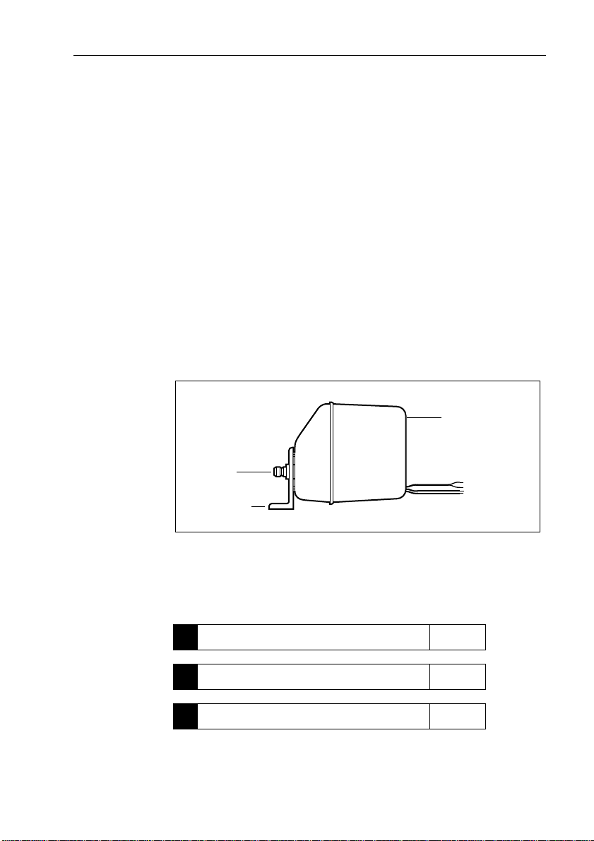
The main parts of the drive a re:
• a rugged electric motor, that drives a precision epicyclic gearbox
via a high tensile drive belt
• an electromagnetic clutch that transmits high torque loads
without slipping
Motor, gearbox
and clutch assembly
Figure 1: Main parts of the rotary drive
Contents
This guide contains:
Drive shaft
Mounting foot
Product specifications page 4
1
Installation instructions page 5
2
Maintenance information page 15
3
Clutch cable
Motor cables
D5082-1
Page 5
4 Rotary Drive - Installation Guide
Specifications
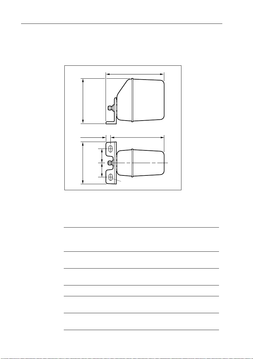
Drive dimensions
274 mm (10.8 in)
195 mm
(7.7 in)
256 mm (10 in)20 mm (0.8 in)
60 mm
184 mm
(7.2 in)
Figure 2: Drive dimensions
(2.4 in)
60 mm
(2.4 in)
2 slots to accept
12 mm (0.5 in) bolts
D5087-1
Drive specifications
Table 1: Drive specifications
Performance
(at nominal voltage)
Maximum boat
displacement
Peak output torque 20 Nm
Maximum shaft speed 33 rpm 33 rpm
Recommended hardover
to hardover time (no load)
Power consumption
(typical average)
Type 1 (T1)
M81135 (12 V)
Type 2 (T2)
M81136 (12 V)
M81137 (24 V)
10,000 kg
(22,000 lb)
20,000 kg
(44,000 lb)
34 Nm
(180 lb.in)
(300 lb.in)
10 sec 10 sec
24-48 W 60-84 W (12 V)
72-120 W (24 V)
Page 6

Rotary Drive - Installation Guide 5
Table 1: Drive specifications (contd)
Other information (applies to Types 1 and 2)
protected for use in engine compartments
CE approvals - conforms to:
89/336/EC (EMC), EN60945:1997
94/25/EC (RCD), EN28846:1993
Installation instructions
Parts required
T o install this drive you will need:
• Parts supplied:
• rotary drive
• mounting foot
• spacing shims (x3)
• Additional parts:
• suitable securing bolts and lock washers/lock nuts (see
page 9)
• suitable sprockets and grub screws for drive and steering
system (see page 9)
• thread-locking compound
• suitable drive chain (see page 9)
• suitable cable and electrical connectors for the drive motor
and clutch (see page 13)
Note: Make sure you have obtained these additional parts before you
start installation.
Page 7

6 Rotary Drive - Installation Guide
Installation steps
WARNING: Electrical safety
Make sure you have switched off the power supply before you
start installing this product.
Follow these steps to install your rotary drive unit:
Consult the EMC installation guidelines. page 6
1
Mount the drive. page 8
2
Connect to the course computer. page 13
3
Complete the post-installation check. page 15
4
Ï
Ï
Ï
1. EMC installation guidelines
All Raymarine equipment and accessories are designed to the best
industry standards for use in the recreational marine environment.
Their design and manufacture conforms to the appropriate
Electromagnetic Compatibility (EMC) standards, but correct
installation is required to ensure that performance is not
compromised. Although every effort has been ta ken to ensure that
they will perform under all conditions, it is importa nt to understand
what factors could affect the operation of the product.
The guidelines given here describe the conditions for opti mum EMC
performance, but it is recognized that it may not be possible to meet
all of these conditions in all situations. T o ensure the best possible
conditions for EMC performance within the constraints imposed by
any location, always ensure the maximum separation possible
between different items of electrical equipment.
For optimum EMC perform ance, it is recommended that wherever
possible:
• Raymarine equipment and cables connected to it are:
Page 8

Rotary Drive - Installation Guide 7
• At least 3 ft (1 m) from any equipment transmitting o r cables
carrying radio signals e.g. VHF radios, cables and antennas.
In the case of SSB radios, the distance should be increased to
7ft (2m).
• More than 7 ft (2 m) from the path of a radar beam. A radar
beam can normally be assumed to spread 20 degrees above
and below the radiating element.
• The equipment is supplied from a se parate battery from that used
for engine start. Voltage drops below 10 V, and starter motor
transients, can cause the equipment to reset. This will not damage
the equipment, but may cause the loss of some information and
may change the operating mode.
• Raymarine specified cables are used. Cutting and rejoining these
cables can compromise EMC performance and must be avoided
unless doing so is detailed in the installation manual.
• If a suppression ferrite is attached to a cable, this ferrite shou ld not
be removed. If the ferrite needs to be removed during installation
it must be reassembled in the same position.
Suppression ferrites
The following illustration shows t ypical cable suppression ferrites
used with Raymarine equipment. Always use the ferrites supplied by
Raymarine. This product has ferrites mounted internall y.
D3548-2
Figure 3: Typical suppression ferrites
Connections to other equipment
If your Raymarine equipment is to be connected to other equipment
using a cable not supplied by Raymarine, a suppression ferrite MUST
always be attached to the cable near to the Raymarine unit.
Page 9

8 Rotary Drive - Installation Guide
2. Mounting the drive
Mounting the drive involves four main steps:
• securing the drive to the boat
• connecting the drive to the steering system
• ensuring correct sprocket alignment and chain tension
• completing a steering check
Securing the drive
Mounting location
Before you secure the drive to your boat, you must first check the
suitability of the mounting location.
CAUTION:
Consult the boat manufactur er if you have any doubt about the
strength or suitabili ty of the mounting location.
• Structural strength:
• This drive produces a considerable amount of force, so yo u
must mount it on a solid structure (i.e. a substantial frame
member) in the boat. In some cases you may need to build a
special frame to mount the drive unit.
• T o prevent excess noise and vibration, do not attach this drive
to any structures that support cabins.
• Drive orientation:
• The drive can be mounted on a vertical or horizontal surface.
• If necessary , you can rotate the mounting foot through 90
degrees to provide a more convenient mounting position (as
shown in Figure7). T o do this: remove the four screws
securing the mounting foot to the drive unit, rotate the
mounting foot, then replace the screws.
• Additionally, the drive may face either way as you can correct
the steering direction by reversing the polarity of the motor
connections at the course computer (see Figure 8).
• General position:
• Refer to the EMC installation guidelines (page 6)
• Make sure the drive will be accessible for future servicing.
Page 10

Rotary Drive - Installation Guide 9
• Environment:
• This drive is not waterproof, so yo u should mount it in a dry
location, clear of any bilge water.
Mounting bolts
Attach the mounting foot with two stainless steel M12 (
1
/
inch) bolts
2
and lock nuts/lock washers.
Note: Before finally tightening the bolts you must check sprocket
alignment (see page 12) and chain tension (see page 12).
Note: Al ways mount the drive as securely as possibl e to make sure it
performs reliably and the chain remains correctly aligned.
Connecting to the steering system
The rotary drive is connected to the steering system by a chain drive
between a sprocket on the drive and a sprocket on the boat’s steering
shaft.
Note: M ost steering gear manufacturers suppl y special autopilot
drive attachments, and many include this as st andard. Contact your
steering gear manufacturer f or more information.
When you have checked with the steering gear manufacturer about
how and where you can attach the autopilot chain to the boat’s
steering system, you need to:
• determine the sprocket and chain sizes
• attach and align the sprockets and chain
• tension the chain correctly
Determining the sprocket and chain sizes
Chain size
Recommended chain size: standard
3
/
inch pitch.
8
Sprocket sizes
T o determine the sprocket sizes required at the steering shaft and
rotary drive:
• count the number of times the steering shaft turns when you move
the rudder from hardover to hardover
Page 11

10 Rotary Drive - Installation Guide
• use Figu re 4 to determine the sprocket sizes required at the
steering gear shaft (steering sprocket) and at the rotary drive
(drive sprocket) by:
• reading up from the number of steering shaft turns (on the
horizontal axis) until you reach the line for T ype 1 or T ype 2
drive (as appropriate)
• reading across (to the vertical axis) to identify t he appropriate
steering and drive sprocket sizes from the table on the left
• for example, if the steering shaft turns twice when the rudder
moves from hardover to hardover you will need (as indicated by
the dotted lines on Figure 4):
• a 13 tooth drive sprocket and 38 tooth steering sprocket if you
have a T ype 1 rotary drive
• a 15 tooth drive sprocket and 57 tooth steering sprocket if you
have a T ype 2 rotary drive
Rotary drive - sprocket sizes
7
Steering sprocket
Drive sprocket
13
76
6
15
76
5
13
57
57
57
Chain reduction ratio
38
38
38
25
25
25
25
25
4
3
2
Type 2
1
Type 1
15
17
13
15
17
13
15
17
19
25
1
Number of steering shaft turns (hardover to hardover)
23456
D5083-1
Figure 4: Rotary drive sprocket sizes
Note: T he sprocket sizes in Figure 4 provide good steering
performance for most boats. If you think your boat may have unusual
steering characteristics, contact Raymarine’s T echnical Services
Call Center or an Authorized Service Representative for advice.
Page 12

Rotary Drive - Installation Guide 11
Obtaining the steering sprocket
Obtain the appropriate sized steering sprocket from the steering
system manufacturer.
Obtaining the drive sprocket
Y our Raymarine dealer can supply the fol lowing drive sprockets
(suitable for a
3
/
inch pitch chain):
8
• 13 tooth: part number M81 182
• 15 tooth: part number M81 183
• 17 tooth: part number M81 184
• 19 tooth: part number M81 185
• 25 tooth: part number M81 186
CAUTION:
T o stop the drive sprocket r otating on the drive shaft, the shaft
1
has a
/
inch square projection (a woodruff key) that fits into a
8
notch (or keyway) at the centre of the sprocket. If you use a nonRaymarine drive sprock et, its bore and keyway di mensions must
fall within the ranges specified in Figure 5 for it to lock correctly
to the drive shaft.
3.22 mm – 3.24 mm
(0.127 in – 0.1275 in)
keyway
15.89 mm – 15.9 mm
(0.6256 in – 0.6275 in)
bore
grub screw
9.46 mm – 9.61 mm
(0.3725 in – 0.3785 in)
19 mm
(0.75 in)
Figure 5: Sprocket bore and keyway dimensions
12.7 mm
(0.5 in)
D5084-1
Page 13

12 Rotary Drive - Installation Guide
Attaching drive and steering sprockets
Note: Each sprocket must be keyed and then screwed to the shaft with
a grub screw secured with thread- locking compound.
Checking sprocket alignment and chain tension
Aligning drive and steering sprockets
Both sprockets must be accurately aligned to run in the same plane
when viewed from the side. Check for correct alignment by holding a
straight edge between the edge of the sprockets (see Figure 6).
Steering sprocket
Drive
sprocket
Drive
sprocket
Steering sprocket
Side view
End view
D5085-1
Figure 6: Sprocket alignment
Adjusting the chain tension
Adjust the chain tens ion until it is just tig ht, so ther e is minima l lost
motion between the drive sprocket and the rudder stock.
Note: If the chain tension is not set correctly, the r esulting lost motion
will impair steering performance.
T o adjust chain tension:
• Drives mounted horizontally: place as many of the supplied
shims as necessary under the mounting foot (see Figure7).
• Drives mounted vertically: use the slots i n the mounting foot to
move the drive up or down (see Figur e7).
Page 14

Rotary Drive - Installation Guide 13
D5086-1
Figure 7: Adjusting chain tension
Steering check
When you have tensioned the chain correctly , turn the steering wheel
from hardover to hardover to check that the chain and sprockets move
freely and are correctly aligned.
WARNING:
Keep clear of moving steering systems at all times. Protect
moving parts from access d uring normal use.
3. Connecting to the course computer
WARNING: Electrical safety
Make sure the power su pply is swi tched off befo re you make any
electrical connections.
The rotary drive has electrical connections for:
• drive motor: two single-core cables: red and black
• clutch: a two-core cable with red (+) and blue (-) cores
Page 15

14 Rotary Drive - Installation Guide
Follow these steps to connect the rotary drive to the course computer:
1. Measure the total distance of cable run from the drive unit to the
course computer:
• use T able 2 to identify the appropriate motor cable size
• use at l east 1.5 m m
2
(16 A WG) copper cable for the clutch
2. Join these cables to the drive cables using appropriate electrical
connectors or junction boxes at the correct power rating.
3. Route the cables back to the course computer, taking into account
the EMC installation guidelines (see page 6).
4. Connect the cables to the course computer (see Figure 8):
•
CLUTCH terminals: red core to +ve, blue core to -ve.
•
MOTOR terminals: at this stage you can connect either motor
cable to either terminal. Y ou will check these connections
after installing the rest of the autopilot system.
Table 2: Recommended cable sizes
Cable length
(drive to course computer)
Type 1 drive
up to 3m (10ft)
up to 5m (16ft)
up to 7m (23ft)
up to 10m (32ft)
up to 16m (52ft)
Type 2 drive 12V
up to 5m (16ft)
up to 7m (23ft)
up to 16m (52ft)
Type 2 drive 24V
up to 3m (10ft)
up to 5m (16ft)
up to 10m (32ft)
up to 16m (52ft)
Cable gauge
(AWG)
14
12
10
8
6
10
8
6
12
10
8
6
Copper area
2
)
(mm
2.5
4
6
10
16
6
10
16
4
6
10
16
Page 16

Rotary Drive - Installation Guide 15
+–
A
OFF
SWITCH
B
MOTORPOWER
–
–
–
SOLENOID CLUTCH
+
+–+–
lk CLUTCH MOTORPOWER
1
2
Type 150/400 course computer
Figure 8: Course computer connections
4. Post installation checks
Check the following points after installing the drive:
1. Is the drive secured to a substantial structure on the boat?
2. Have you used suitable steering and drive sprockets for the boat ?
3. Are the drive and steering sprockets in line when viewed side-on?
4. Have you securely locked both sprockets to the shafts?
5. Have you tensioned the chain correctly?
6. Are the motor and clutch cables correctly routed and securely
connected to the course computer?
7. Complete a hand-steering check: Do the chain and sprockets
move freely and in correct alignment from hardover to hardover?
Note: When you have installed the entire autopilot system, you will
need to complete an autopilot steering check. Refer to the control unit
handbook for more details.
Maintenance
On a regular basis:
• check all connections and mountings are secure
• check chain and sprockets are correctly aligned and tensioned
• lightly grease sprockets and chain
• check cables for signs of wear or damage
Note: If t his drive is used heavily, we recommend that it is serviced
every two years by a Raymarine Authorized Service Representative.
Type 100/300 course computer
D5080-1
Page 17

16 Rotary Drive - Installation Guide
EMC servicing and safety guidelines
• Raymarine equipment should be serviced only by auth orized
Raymarine service technicians. They will ensure that service
procedures/replacement parts used will not affect performance.
There are no user serviceable parts in any Raymarine product.
• Some products generate high voltages, so never handle cable s or
connectors when power is being supplied to the equipment.
• When powered up, all electrical equipment produces
electromagnetic fields. These can cause adjacent pieces of
electrical equipment to interact with one another, with a
consequent adverse effect on operation. In order to minimize
these effects and enable you to get the best possible performance
from your Raymarine equipment, guidelines are given in the
installation instructions, to enable you to ens ure minimum
interaction between different items of equipment, i.e. ensure
optimum Electromagnetic Compatibility (EMC).
• Always report EMC-related probl ems to your nearest Raymarine
dealer. W e use such information to improve our quality standards.
• In some installations, it may not be possi ble to prevent the
equipment from being affected by ext ernal influences. In general
this will not damage the equipment but it can lead to spurious
resetting action, or momentarily may result in faulty operation.
Product support
Raymarine products are supported by a worldwide network of
distributors and Authorized Service Representa tives. If you
encounter any difficulties with thi s product, please contact either
your national distributor , or your service representative, or the
Raymarine T echnical Services Call Center.
Raymarine Ltd
Anchorage Park
Portsmouth, Hampshire
England PO3 5TD
Telephone +44 (0)23 9269 3611
Fax +44 (0)23 9269 4642
www.raymarine.com
Raymarine Technical Services Call Center
UK: +44 (0)23 9271 4713 or
+44 (0)23 9269 3611 ext. 1083
Raymarine Inc
22 Cotton Road, Suite 280
Nashua
NH 03063-4219, USA
Telephone +1 603 881 5200
Fax +1 603 864 4756
www.raymarine.com
USA: +1 603 881 5200 or
1-800-539-5539 ext. 2333
 Loading...