

Page 1

Raytech RNS V6.1
User’s Guide
Document Number: 81260_2
October 2008
Page 2

Trademarks and registered trademarks
Autohelm, HSB, Raymarine, RayTech, Sail Pilot, SeaTalk and Sportpilot are
registered trademarks of Raymarine Limited. Apelco is a registered trademark of Raymarine Holdings Limited (Registered in all major marketing
territories).
AST, Autoadapt, Auto GST, Autoseastate, Autotrim, Bidata, Marine Intelligence, Maxiview, On Board, Raychart, Raynav, Raypilot, Raystar, ST40,
ST60, Seaclutter, Smart Route, Tridata and Waypoint Navigation are trademarks of Raymarine Limited.
Windows and NT are registered trademarks of Microsoft Inc.
Pentium is a registered trademark of Intel.
NVIDIA and GeForce are trademarks or registered trademarks of NVIDIA
Corp.
Maptech is a registered trademark of Maptech.
C-Map and C-Map NT+ are registered trademarks of C-Map SRL.
Navionics is a registered trademark of Navionics SpA.
All other product names mentioned are trademarks or registered trademarks (if applicable) of their respective companies.
© Raymarine plc 2008
Page 3

i
Contents
Contents............................................................. i
Important information .................................... 1
Safety notices.........................................................................1
Intended use ..........................................................................1
Disclaimers............................................................................. 1
The limits of electronic navigation .........................................2
About this manual.................................................................. 2
Conventions used...................................................................3
Product use ............................................................................3
System integration .................................................................3
Technical accuracy .................................................................3
Copyright................................................................................3
System overview and features.....................5
Introduction .......................................................................... 5
What do I get in the box? ..................................................... 5
System overview ................................................................... 6
System features .................................................................... 6
Easy marine navigation ....................................................... 6
Chart formats ...................................................................... 6
Comprehensive Weather/ Oceanographic reporting............ 7
Advanced graphical user interface ...................................... 7
Navionics Platinum chart card............................................. 7
Sailboat racing .................................................................... 7
Fishing (US market only) ..................................................... 7
System requirements.....................................9
Introduction ...........................................................................9
System requirements .............................................................9
Minimum system requirements............................................9
Optimum system requirements ............................................9
Is my PC ready to use RayTech? ............................................10
Upgrading drivers and adapters ............................................12
Driver update .......................................................................12
DirectX .................................................................................13
Useful websites....................................................................14
Getting started ............................................... 15
Introduction ...........................................................................15
Installing RayTech .................................................................15
Installation from a CD-ROM.................................................15
Installation from the Internet ...............................................15
Starting to use RayTech .........................................................16
License keys .........................................................................16
Running RayTech for the first time.......................................17
Using RayTech on a new computer......................................19
Continuing To Use RayTech ...................................................19
Operating modes .................................................................19
Simulator .............................................................................19
Raytech Planner - Simulate mode. .......................................20
RayTech Planner only operates in ‘Simulate mode’. If you want
to change the Simulator’s automatic settings, you can taylor the
menu to suit your needs. The Simulator menu is available to edit:
20
Setting up RayTech ................................................................20
Page 4

ii RayTech RNS V6.1 - Users Guide
Installing instruments to RayTech ..........................................21
RayTech Tools ......................................................................21
File/Setup/Instruments feature .............................................21
Installing charts .....................................................................25
C-MapNT+/PC charts from CD-ROM ....................................25
Maptech cartography ...........................................................25
Navionics cartography..........................................................26
RayTech chart installer .........................................................26
The user interface and controls .................. 27
Introduction ...........................................................................27
The screen .............................................................................27
Interface controls ...................................................................27
Drop down menus................................................................28
Toolbars ...............................................................................28
Softkeys................................................................................28
Right mouse menus..............................................................28
Pathfinder panel...................................................................29
Displaying information ..........................................................29
Selection dialog box.............................................................29
Action box............................................................................30
Data box...............................................................................30
Alert and information dialog box .........................................30
Application information box.................................................30
Changing what you see on the screen ...................................31
Moving around a split page .................................................31
Using charts..................................................... 33
Introduction ...........................................................................33
Use your charts safely .......................................................... 33
The chart screen .................................................................... 33
Opening a chart .....................................................................33
Moving around the chart .......................................................34
Chart panning ...................................................................... 34
Zooming...............................................................................34
Finding your boat on the chart.............................................34
Choosing a chart type ...........................................................34
Chart layers..........................................................................35
Chart order...........................................................................35
Chart quilting.......................................................................36
Using Platinum cartography ........................ 39
Introduction ...........................................................................39
2D cartography ....................................................................39
3D bathymetric charts..........................................................39
New 2D chart features ..........................................................40
Aerial photo overlay.............................................................40
Pilot book.............................................................................41
2D chart enhancements .........................................................42
Business services information ..............................................42
Find nearest .........................................................................42
Search port by name ............................................................ 43
Wrecks data.........................................................................43
Coastal roads ....................................................................... 44
US inland waterways ...........................................................44
3D bathymetric chart application ..........................................45
The application ....................................................................46
Page 5

iii
The controls......................................................................... 46
The operating modes........................................................... 46
Using 2D and 3D charts together ........................................ 49
Navigating with 3D Charts .................................................. 49
Working with waypoints ...............................51
Introduction .......................................................................... 51
What is a waypoint? ............................................................. 51
Placing a waypoint ............................................................... 51
...at the cursor’s current position......................................... 51
... at the boat’s current position .......................................... 51
... at a known position ........................................................ 51
Placing a man overboard marker .......................................... 53
Changing a waypoint symbol ............................................... 53
Navigating to a waypoint ..................................................... 54
...using the WAYPT button .................................................. 54
...using the cursor................................................................ 54
...using the waypoints list ................................................... 54
Moving a waypoint ............................................................... 54
Edit waypoint details ............................................................ 55
Organizing waypoints ........................................................... 55
Deleting a waypoint or waypoint folder? .............................. 56
Waypoint recycle bin ............................................................ 56
Transferring route and waypoint data .................................. 57
Working with routes ......................................61
Introduction .......................................................................... 61
What is a route? ................................................................... 61
Creating a route .................................................................... 61
Add a waypoint to a route ...................................................62
Deleting a waypoint.............................................................63
Choosing a route..................................................................64
Following route....................................................................64
Monitoring the course ...........................................................64
Restart XTE ..........................................................................65
Next Leg and Previous Leg...................................................65
Using tides and currents................................67
Introduction ...........................................................................67
Setting the region ................................................................67
Tides ......................................................................................68
Open nearest tides...............................................................68
Currents .................................................................................69
Open nearest currents..........................................................69
Working with radar (Analog)........................ 71
Introduction ...........................................................................71
Displaying radar in a new page .............................................71
The radar picture ...................................................................71
Changing how the radar picture is shown .............................72
Head - up (H-UP)..................................................................72
North - up (N-UP).................................................................72
Course - up (C-UP) ...............................................................72
Getting the best radar picture ...............................................72
Gain ....................................................................................72
FTC.......................................................................................73
Sea mode .............................................................................73
Gain mode ...........................................................................73
Page 6

iv RayTech RNS V6.1 - Users Guide
Tune .....................................................................................73
Making targets clearer? .........................................................74
Interference rejection ...........................................................74
Expansion.............................................................................74
Wakes ..................................................................................74
Setting up the radar display ...................................................74
Short range scales................................................................74
Long range scales.................................................................74
Changing the displayed range..............................................75
Marking a position on-screen ................................................75
Using radar to help avoid a collision .....................................75
Range rings ..........................................................................75
VRMs/EBLs. ..........................................................................76
Guard zones.........................................................................77
Placing a guard zone............................................................78
MARPA ..................................................................................78
Safety Notices ......................................................................78
What is MARPA?..................................................................78
Target and vector history .....................................................79
Target history .......................................................................80
MARPA targets.....................................................................80
Using the Radar (Digital)............................... 83
Radar setup ...........................................................................83
Select scanner ......................................................................83
Scanner setup.......................................................................83
Powering on/off the various scanner operating modes ..........84
Radar range and image quality .............................................85
Range...................................................................................85
Image quality ....................................................................... 86
Side lobes.............................................................................86
Indirect echoes.....................................................................87
Multiple echoes....................................................................87
Blind sectors ........................................................................87
Sea clutter............................................................................ 87
Rain or snow clutter............................................................. 88
Mutual radar interference .................................................... 88
Radar window overview ........................................................ 89
Your position .......................................................................89
Operation modes .................................................................89
Other vessels or objects .......................................................89
Factors affecting echo strength............................................89
Using waypoints with the radar ............................................90
Radar display options ............................................................90
Orientation...........................................................................90
Setting the motion mode .....................................................92
Tuning the radar display: .......................................................93
Gain .....................................................................................93
Gain presets.........................................................................93
Manually adjusting gain settings .........................................93
Gain .....................................................................................93
Color Gain............................................................................94
Radar colors.........................................................................94
Rain clutter ..........................................................................94
Sea clutter............................................................................ 94
Super HD adjustments ...........................................................94
Page 7

v
Antenna boost..................................................................... 94
Power boost ........................................................................ 95
Tuning the radar display: ENHANCE ECHOES ....................... 95
Interference rejection .......................................................... 95
Expansion............................................................................ 95
Wakes ................................................................................. 95
Radar range .......................................................................... 96
Synchronizing radar range and chart scale.......................... 96
Measuring distance, range and bearing ............................... 96
Range rings ......................................................................... 96
Bearing and range............................................................... 97
The Variable Range Marker (VRM) and Electronic Bearing Line
(EBL).................................................................................... 97
Variable Range Marker........................................................ 97
Electronic Bearing Marker ................................................... 98
Combined range and bearing.............................................. 99
Tracking a target with a VRM or EBL .................................. 99
Floating VRM and EBL......................................................... 99
Using radar to track objects .................................................. 100
Guard zones ........................................................................ 100
MARPA................................................................................ 101
Displaying vessel identity (AIS)............................................ 104
Automatic Identification System (AIS)........105
Introduction .......................................................................... 105
What is AIS? ......................................................................... 105
Classes of AIS data.............................................................. 105
What do I need to run AIS? .................................................. 106
AIS baud rate selection ..........................................................106
Selecting the AIS function .....................................................107
How is AIS data displayed? ...................................................108
AIS Target symbols...............................................................109
Viewing target information..................................................109
MARPA and AIS options ......................................................110
Safety messages...................................................................111
AIS Alarms .............................................................................111
AIS Layer Setup Menu ...........................................................111
Working with sonar........................................ 113
Introduction ...........................................................................113
The sonar screen ...................................................................113
Displaying sonar in a new page ...........................................113
Presets ...................................................................................113
Changing the screen view .....................................................114
Background color.................................................................114
Scrolling speed.....................................................................114
Target depth ID ....................................................................115
Improving the underwater view ............................................115
Changing the range .............................................................116
Selecting the operating frequency........................................116
Making the picture clearer ....................................................117
Gain mode ...........................................................................117
Color gain mode ..................................................................117
TVG......................................................................................118
Color Threshold....................................................................118
Getting a clear picture of the bottom ....................................120
Page 8

vi RayTech RNS V6.1 - Users Guide
Getting a live image from below the boat .............................122
Isolating objects near the bottom ..........................................125
Getting a closer view ...........................................................125
Marking an on-screen position ..............................................125
Measuring an object’s depth and distance ............................127
Sonar alarms ..........................................................................128
Shallow water alarm ............................................................128
Deep water alarm.................................................................128
Fish alarm ............................................................................129
Sonar data recording and playback .......................................129
RayTech advanced features.......................... 133
Introduction ...........................................................................133
Weather information .............................................................133
Advanced Weather and Satellite Fishing Maps ....................133
The screen............................................................................134
Getting weather information from the internet....................135
Getting weather, Sea Surface Temperature (SST) and Plankton
information by E-mail...........................................................136
3rd Party GRIB (Weather) files .............................................137
Viewing a weather file .........................................................137
Configuring the Weather Layer ............................................137
Viewing an SST and Plankton file.........................................137
Configuring the Fishing Layer (SST and Plankton)................138
Animating weather files .......................................................139
Measuring distances on a chart .............................................141
Creating and modifying databoxes ........................................143
Modifying a databox............................................................143
Creating a databox ..............................................................145
Modifying a channel ............................................................145
Using the font selector.........................................................145
Polar plotting ........................................................................147
Data collection.....................................................................147
Entering and editing data ....................................................147
Graphing and reading a polar plot.......................................151
Instrument calibration for accurate data.............................. 153
DataTrak ................................................................................154
Pre-start display ....................................................................157
Route optimization ................................................................160
Navigation numbers ..............................................................163
Engine panel .........................................................................164
Using video .................................................... 167
Introduction ...........................................................................167
The user interface .................................................................. 167
RNS mode........................................................ 171
Introduction ...........................................................................171
USB navigation keyboard ......................................................171
The controls .........................................................................171
Installing the RNS keyboard ..................................................173
Setting up RayTech for use with the RNS keyboard ...............173
Troubleshooting RayTech ............................. 175
Introduction ...........................................................................175
Technical support ..................................................................182
Charts ..........................................................................183
Vector ..................................................................................183
Page 9

vii
Raster.................................................................................. 183
Aerial imagery..................................................................... 184
Radar .......................................................................... 185
Scanner ............................................................................... 185
Standard range scales ......................................................... 186
Identifying false echo returns .............................................. 187
Sonar .......................................................................... 191
Boat speed .......................................................................... 192
Target depth........................................................................ 192
Target size........................................................................... 192
Transducer frequency .......................................................... 192
Installation Guidelines............................................. 195
Suppression Ferrites ............................................................ 195
Connections to other equipment......................................... 195
System integration ................................................................ 196
What is System Integration? ............................................... 196
NMEA basics ....................................................................... 197
RS-232 basics ...................................................................... 197
Connecting RayTech to your instruments ............................ 199
Connecting directly to an NMEA GPS.................................. 199
Connecting directly to NMEA equipped instruments........... 200
SeaTalkhs ............................................................................ 200
SeaTalk devices ................................................................... 204
RayTech SeaTalk/PC/NMEA Interface: ................................ 205
Mounting the interface box................................................. 205
RayTech SeaTalk/PC/NMEA Interface box troubleshooting . 206
Connecting NMEA direct to Raymarine Pathfinder displays: 206
Connecting an hsb2 PCMCIA PC kit .................................... 207
PCI to PCMCIA cardbus adapter ..........................................208
Connecting an hsb2 to USB2.0 interface..............................208
Connecting to B & G Instruments.........................................208
Connecting to KVH Instruments...........................................209
Connecting to Ockam Instruments.......................................209
Connecting a USB C-Card Reader ........................................210
Fully integrated system ........................................................210
Integrated system checks.....................................................210
Toolbars...................................................................... 213
Main menu...........................................................................213
Standard toolbar ..................................................................218
Routes and waypoints toolbar .............................................219
Charting toolbar...................................................................219
Animation toolbar................................................................220
Alarms toolbar .....................................................................221
Tides/Currents toolbar..........................................................221
3D toolbar............................................................................222
Fishing toolbar .....................................................................223
Yacht racing toolbar.............................................................223
Pre-start toolbar...................................................................224
Weather toolbar...................................................................224
Databox toolbar...................................................................225
List of abbreviations ................................................ 227
Glossary of terms...................................................... 229
Page 10

viii RayTech RNS V6.1 - Users Guide
Page 11
Important information 1
Important information
Safety notices
WARNING
Navigation aid
When this product is used within a navigation system, it is
only an aid to navigation. It’s accuracy can be affected by
many factors, including equipment failure or defects, environmental conditions and improper use or handling. It is
the user’s responsibility to exercise common prudence
and navigational judgements. This product should not be
relied upon as a substitute for such prudence and judgement. Always maintain a permanent watch so that you can
respond to situations as they develop.
WARNING
CAUTION
Navionics CF Card Reader
The Navionics CF card reader has been designed and
tested for home and dockside planning use only and has
not been tested to marine standards for ruggedness or
interference with other devices on board the vessel.
Raymarine cannot accept responsibility or liability for any
damage to the card reader, associated systems and equipment or compatibility issues arising from its use while
underway.
Intended use
RayTech V6.1 is intended for recreational marine use. Users should note that
only authorized government charts and associated Notices to Mariners
contain all the information required for safe navigation
Product installation
This equipment must be installed and operated in accordance with the Raymarine instructions provided within
this guide. Failure to do so could result in poor product
performance, personal injury, and/or damage to your boat.
Disclaimers
This electronic chart is an aid to navigation designed to facilitate the use of
authorized government charts, not to replace them. Only official government
charts and notices to mariners contain all of the current information needed
for the safety of navigation, and the Captain is responsible for their prudent
use.
Page 12

2 RayTech RNS V6.1 - Users Guide
This program and its charts do not excuse the user from carrying the required
official charts and documents.
Raymarine does not warrant that this product is error free or that it is
compatible with products manufactured by any person or entity other than
Raymarine.
This product utilizes digital chart data, and electronic information from the
Global Positioning System (GPS) and weather information which may contain
errors. Raymarine does not warrant the accuracy of such information and you
are advised that errors in such information may cause the product to
malfunction or give incorrect readings. Raymarine is not responsible for
damages or injuries caused by your use or inability to use the product, by the
interaction of the product with products manufactured by others, or by errors
in chart data or information utilized by the product provided by third parties.
Except for the limited warranty regarding the magnetic media contained in
the license agreement accompanying the product, this product is provided
‘AS IS’ without warranty of any kind, either express or implied, including but
not limited to the implied warranties of merchantability and fitness for a
particular purpose, and any others which may arise from course of
performance, course of dealing, or usage of trade.
The limits of electronic navigation
Experienced navigators know not to rely on a single method of navigation for
determining their position. Two or more methods should be used to
determine position and guard against errors placing you or your boat in a
dangerous position. Global Positioning System (GPS) based electronic
navigation is an amazing application of technology, but like all other
technology, has limits. A wise navigator will understand these limits and how
they affect the safety of their boat and crew.
The Global Positioning System is made up of components starting with
ground based computers to monitor and maintain the system made up of 24
satellites in orbit around the earth. The system ends at your boat’s receiver.
Like all systems it is not perfect and any part of it can fail. GPS accuracy varies
between 2 and 50 meters.
NMEA 0183 1.0 / 1.5 only supports 2 digits of latitude and longitude, giving a
precision of approximately 60 feet.
NMEA 2.0 / 2.1 supports 3 digits of latitude and longitude, giving a precision
of approximately 6 feet.
Another limitation to the system accuracy is digital charts. These electronic
charts are made by highly skilled cartographers. Surveys on which the
cartography is based, were in some cases, made over 50 years ago. So
despite everyone’s best efforts, it may be possible to have errors in the final
product.
Lastly, RayTech software was developed by highly skilled and talented
software engineers and underwent a rigorous test and quality assurance
program before being released. However, it is possible that software issues or
malfunctions may remain undetected in the software. While Raymarine make
every effort to find, fix and repair software issues as they are discovered, this
product is specifically not promised to be issue free.
About this manual
This manual describes how to install and operate RayTech V6.1 marine
navigation software. It assumes that the personal computer (PC) on which
the software is to be installed meets the requirements for running this version
of RayTech, and that all peripheral equipment intended to be operated with it
is compatible and has been correctly installed.
This manual is intended for users with varying technical and
marine abilities, but assumes a general level of knowledge of
PC use and nautical terminology and practices.
This manual gives an overview of RayTech V6.1, and details the main
functions and how to operate them. There are several ways that a task can be
Page 13

Important information 3
completed, experiment, find the way of using RayTech that best suits your
way of working.
Conventions used
In this manual the following conventions will be used:
• RayTech refers to RayTech V6.1.
• The names of keyboard keys are printed in boldface, such as Enter.
• Italics are used to show names, such as
Find Vessel, except with notes.
• Instructions using menu options are written as menu option/submenu
option. For example, the instructions might read ‘Select File/ Layers’.
This means go to the File menu on the drop-down menus and select it. A
submenu will appear that contains the Layers option for you to select.
• ‘Click’ refers to clicking the mouse button. Unless otherwise stated, it
refers to the left mouse button once.
• ‘Right click’ refers to clicking the right mouse button once.
• ‘Double click’ means to click the left mouse button twice quickly.
Open Chart
, or softkeys such as
Product use
You may not use this product unless you agree to the terms and conditions of
the license agreement.
In accepting these terms and conditions, you agree to be bound by the terms
of the license agreement and to release and hold Raymarine harmless from
and against any and all claims, obligations and liabilities with respect to the
product, except those specifically reserved in the license agreement.
If you do not agree to the terms and conditions of the license agreement, you
may return the program within thirty (30) days of the date of purchase by
following the instructions contained within the license agreement.
System integration
RayTech V6.1 has been designed to work transparently with Raymarine’s
SeaTalk or SeaTalk
outputs data in National Marine Electronics Association (NMEA) 0183
format. These protocols allow information such as heading, wind speed and
direction, sea temperature and other information to be accessed and
displayed within RayTech. Information generated by RayTech can also be
displayed on your boat’s standard on-board instruments.
If you intend to run RayTech on a laptop computer as part of an integrated
system you should read “Installation Guidelines” on page 195 to ensure
correct connectivity into the system.
hs
data communication networks, or any other device that
Technical accuracy
The technical information contained within this manual, to the best of our
knowledge, was correct at the time of printing. However, Raymarine cannot
accept liability for any inaccuracies or omissions it may contain.
In addition Raymarine’s policy of continuous product improvement may
change specifications without notice. As a result Raymarine cannot accept
liability for any differences between the product and the manual.
Copyright
Under copyright laws use of this manual is intended for the original licensee.
No portion of this manual may be reproduced or transmitted in any form by
any means, electronic or mechanical, including photocopying, recording, or
information storage and retrieval systems, for any purpose other than the
licensee’s use, without the express written permission of Raymarine, and
provided in the licensing agreement between you and Raymarine.
Page 14

4 RayTech RNS V6.1 - Users Guide
Page 15

Chapter 1: System overview and features 5
Chapter 1: System overview and features
1.1 Introduction
This chapter introduces RayTech and covers the following:
• What’s in the box.
•System overview.
1.2 What do I get in the box?
When you open the box containing RayTech, you will find various
components, depending on which package you have purchased.
RayTech V6.1 - Part No.E112111
Component Part No.
RayTech CD-ROM with license key decal 47001-2
RayTech accessory list 47015-1
RayTech User’s Manual 81260-1
Navionics CF Chart Reader E86026
If any of the components are missing, you should contact, in the first
instance, the Raymarine dealer where you purchased your package, or
Raymarine Customer Support, the details of which can be found in the
Technical Support section of this handbook, on page 182.
Accessories
The following accessories are available for RayTech:
Component Raymarine Part No.
Navionics CF Chart Reader E86026
C-Map USB C-Card Reader E86008
SeaTalk to PC Interface E85001
2
hsb
PC (PCMCIA) Kit V6.1
hsb2 PC (USB) Kit V6.1
Serial data cable, DB-9 E86001
RayTech V6.1 Manual 81260-2
hs
SeaTalk
Note:
crossover coupler
The use of the PCMCIA to hsb
E86023
E85005
E55060
2
kit, hsb 2 to USB 2.0 and C-map
USB C-card reader are limited to use on platforms running on
Windows 2000 or XP only
.
Page 16
6 RayTech RNS V6.1 - Users Guide
CAUTION
Navionics CF Card Reader
The Navionics CF card reader has been designed and
tested for home and dockside planning use only and has
not been tested to marine standards for ruggedness or
interference with other devices on board the vessel.
Raymarine cannot accept responsibility or liability for any
damage to the card reader, associated systems and equipment or compatibility issues arising from its use while
underway.
Subscription services
Technical Support, comprehensive weather reporting and fishing updates
require online registration and subscription at www.raymarine.com.
1.3 System overview
RayTech operates within a standard Windows environment, and enables you
to utilize the latest digital charts and Global Positioning System (GPS)
instrumentation to help you navigate your boat virtually anywhere in the
world. RayTech easily interfaces with your boats onboard navigational
systems, offering you the flexibility to allow RayTech to autopilot your boat to
any destination you chose to plot.
RayTech also incorporates the capability to download the latest weather and
oceanographic information and display it on any chart. Advanced features
are included that will enhance RayTech’s route plotting and fishfinding
performance making it an ideal choice for the serious sailor or fisherman.
1.4 System features
RayTech has been designed for ease of use and incorporates the following
features:
Easy marine navigation
RayTech takes the guesswork out of marine navigation by enabling easy and
accurate planning and plotting of simple or complex routes. These can be
stored and re-used, even changed whilst in use to take changing weather
conditions or other factors into account.
Chart formats
RayTech uses the latest digitized versions of the paper charts traditionally
used in marine navigation, and supports the following chart formats:
• Navionics Silver and Gold+.
• Navionics Platinum and Platinum Plus.
• Navionics HotMaps.
• Navionics Fish ‘n’ Chip (US market only).
• C-Map NT and NT Plus.
• Maptech BSB v2.0/v3.0/v4.0 & NOAA RNC.
•Maptech PCX.
• Maptech Photo Regions and Topographical charts.
• SoftCharts Nautical charts and PhotoNavigator.
• NDI/CHS charts.
Note:
Support for viewing Navionics cartography within RayTech is only
possible if the Navionics cartography is contained on a Compact
Flash card, and is served by either a Raymarine Multifunctional
display/network or a Navionics Multi-card reader.
Page 17

Chapter 1: System overview and features 7
Comprehensive Weather/ Oceanographic reporting
RayTech offers you the capability to download and display the latest weather
and ocean conditions, and then superimpose this information upon your
charts in several layers. Weather and oceanographic charts (in GRIB format)
can be downloaded directly from the Internet or requested via e-mail. These
files can be animated to show predicted weather conditions over a specified
period of time. Typical weather files contain information covering a period of
several days, giving you a comprehensive presentation of atmospheric and
marine conditions.
These features require online registration at www.raymarine.com.
Advanced graphical user interface
RayTech is operated via an easy-to-use Graphical User Interface (GUI)
complete with many customizable toolbars, softkeys and ‘floating’ data
boxes. Using an intuitive menu hierarchy, you can display only those tools
that you commonly use, or customize screens to show you only pertinent
information, with just a few mouse clicks. RayTech’s flexible GUI enables you
to quickly and easily tailor its powerful resources to suit your needs.
Navionics Platinum chart card
Compatibility with Navionics Platinum chart card provides you with
enhanced 2D cartography features, and introduces an easy to use 3D chart
format that provides you with a graphical view of land and sea contours
around your boat. Much of the information available on a conventional chart
can be shown in three dimensions, giving you an accurate easy-to-view
image of the area around.
To read Navionics Platinum Chart cards you will need to install a Navionics
Multicard reader - Part No. E86026, or have RayTech connected via SeaTalk
to an E-Series display.
Sailboat racing
The sail racer features are targeted towards the professional sailboat racer,
and include
• DataTrak.
•Polars.
• Route Optimization.
• Advanced weather routing.
• Pre-start display.
• Navigation numbers.
• Specialized racing toolbar.
Fishing (US market only)
The fishing features are targeted towards the serious fisherman. Raymarine
offers subscription services to support the following fishing features:
• Ocean plankton - using data from the Orb View 2 satellite.
• Sea surface temperature (SST) - using data from U.S. Government
weather satellites.
These features require online registration at www.raymarine.com.
hs
Page 18

8 RayTech RNS V6.1 - Users Guide
Page 19

Chapter 2: System requirements 9
Chapter 2: System requirements
2.1 Introduction
This section deals with making sure that your PC is ready to install and run
RayTech and details:
• System requirements.
• Whether your PC is ready to install RayTech.
• Upgrading drivers and adapters.
2.2 System requirements
Before you can begin installing RayTech, you need to make sure that the PC
you intend to use meets the minimum hardware requirements for running
the software. Whilst RayTech will run successfully on the minimum requirement, for best performance, the optimum requirements are recommended.
The minimum and optimum requirements are:
Minimum system requirements
The minimum system requirements are:
• Pentium IV processor.
• 256MB RAM.
• XP with SP2 (Service Pack 2).
•CD-ROM drive.
• Monitor - capable of displaying 1024 x 768 resolution, 16 bit color.
IMPORTANT - In addition to the minimum/optimum requirements you
will also require 1 or more of the following, depending on how RayTech is
to be connected to your instruments system/network:
• Serial port - for connecting to NMEA 0183 or SeaTalk.
• Ethernet port - for connecting to a G or E-Series display using
• PCMCIA port - for connecting to an hsb
• USB 2.0 port - for connecting to a hsb
• USB or USB 2.0 port - for Navionics Multicard Reader or of Serial to
Note:
hs
SeaTalk
hsb2 adaptor.
PCMCIA adaptor.
USB adapter.
.
The use of the PCMCIA to hsb
2
system using a PCMCIA to
2
system using a USB 2.0/
2
kit, hsb 2 to USB 2.0 and C-map
USB C-card reader are limited to use on platforms running on
Windows 2000 or XP only
.
Optimum system requirements
The optimum system requirements are:
• Pentium IV 2GHz processor or equivalent.
• 1GB RAM or higher.
•NVIDIA
• Windows XP SP2.
GeForce graphics card.
Page 20
10 RayTech RNS V6.1 - Users Guide
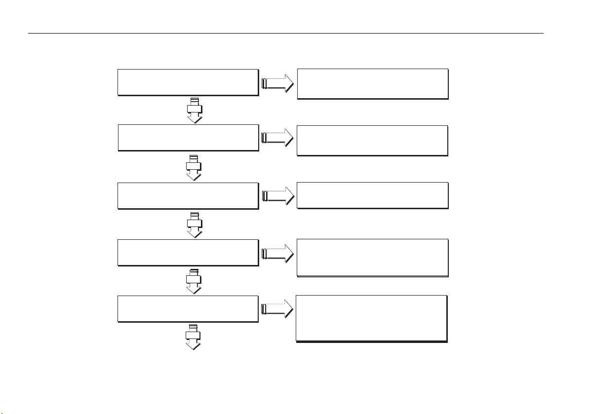
2.3 Is my PC ready to use RayTech?
Is the processor at least a 2GHz Pentium IV?
YES
NO
An upgrade is required.
Visit www.raymarine.com for
details of recommended PCs and adapters
Does the PC have at least 256 mb RAM?
YES
Is the PC running Windows XP?
YES
Does the PC have an NVIDIA
GeForce graphics adapter?
YES
Does the PC have a serial (RS232) port?
YES
NO
An upgrade is required.
Visit www.raymarine.com for
details of recommended PCs and adapters
NO
NO
RayTech RNS requires Windows XP
Raymarine recommends NVIDIA
graphics adapters for best performance
NO
A USB-serial adaptor is required if connecting
to NMEA or SeaTalk
Visit www.raymarine.com for
details of recommended PCs and adapters
D8820_2
Page 21
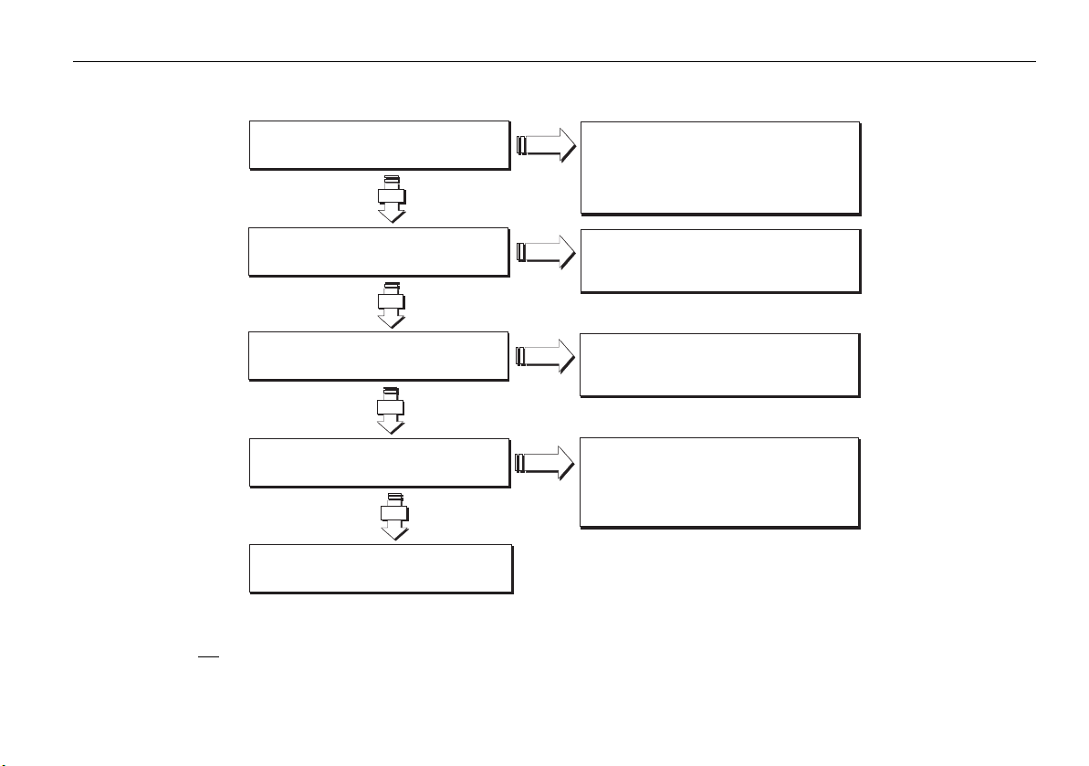
Chapter 2: System requirements 11
Is the PC a laptop?*
NO
NO
You will need a PCI-PCMCIA adaptor if
connecting to hsb display via an hsb PC kit.
2
2
Visit www.raymarine.com for
YES
Does the PC have an USB 2.0 port?
YES
Does the PC have an available Ethernet port
YES
Is the PC's software up-to-date?
NO
NO
NO
NO
NO
details of recommended PCs and adapters
You will need a USB 2.0 port if connecting to an
22
hsb display using the hsb to USB 2.0 interface
You will need an Ethernet port for interfacing
SeaTalk
hs
Get the latest software updates for your PC from
http://windowsupdate.microsoft.com
and the manufacturer of your graphics adapter
YES
(e.g. http://www.nvidia.com) or PC.
D8821_1
Your PC is now ready for RayTech RNS
Note:
*If you are not planning to buy the Pathfinder PC kit, or use RayTech’s hsb2 networking capability for chart, radar, sonar sharing, you can skip this
check.
Page 22
12 RayTech RNS V6.1 - Users Guide
2.4 Upgrading drivers and adapters
Prior to installing RayTech, Raymarine strongly recommend updating your
PC display drivers and verifying that you have the latest versions of
Microsoft DirectX and your Display adapter driver installed.
Note:
It will be necessary to have the PC connected to the Internet for
these checks and updates to be carried out.
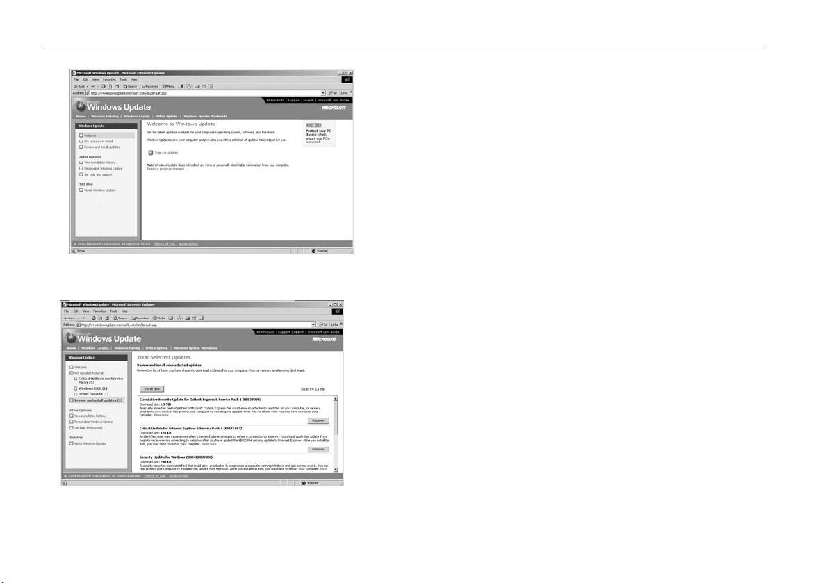
Driver update
To ensure that your PC is current with regard to Windows operating system
patches you should execute the Windows Update utility.
D6966_1
Figure 2-1: Welcome to Windows Update.
D6968_1
Figure 2-2: Review Updates screen.
To run the Windows Update utility:
Start
1. On the computer taskbar, click
2. Select and click
Windows Update
. The pop-up menu is displayed.
. The PC will connect to the Microsoft
Windows Update site.
3. The Welcome screen is displayed. See Figure 2-1
4. Click
Scan for Updates
.
5. Your computer is scanned to find which update patches are required.
The screen updates to show the progress of the scan. When the scan is
complete the Review Updates screen is displayed. See Figure 2-2
6. Click
7. Click
Review and Install Updates.
Install Now
. Installation of the updates starts, with progress
The available updates are displayed.
being shown on screen.
8. Upon completion of the installation a dialog box appears. This will tell
you that installation is complete and that you need to restart your
computer for the updates to be activated.
9. Check Restart Now. Click
OK
. Your computer will restart and Windows
will be updated.
10. Repeat Steps 1-9 until all applicable updates have been installed.
Page 23
Chapter 2: System requirements 13
Note:
Windows update does not always update all drivers. Raymarine
recommend that you check your PC/Hardware manufacturers web
site to check for relevant driver updates.
DirectX
To ensure that you have the latest version of DirectX installed you should
run the DirectX diagnostics utility.
To run DirectX diagnostics utility:
Version number
D6971_1
Figure 2-3: Direct X Diagnostics screen 1.
Display adapter details
1. On the computer taskbar, click
2. Select and click Run. The Run dialog box is displayed.
3. Type in, dxdiag. Click
OK
See Figure 2-3
4. Make a note of the version number installed on your computer.
5. Click the
Display or Display 1
displayed. See Figure 2-4
6. Make a note of the display adapter name, manufacturer, chip type and
driver version installed on your computer (highlighted in the picture
above).
7. Point your Internet browser to -
directx/downloads/default.asp
If the version installed is not current, download and install the latest
version.
8. Point your Internet browser to the display adapter manufacturer’s site
and check the current version available. If the version installed is not
current, download the latest version.
Note:
Laptop users should check their PC Manufacturers web site for rele-
D6972_1
vant video driver updates.
Start.
The pop-up menu is displayed.
. The DirectX diagnostic tool will be displayed.
tab. The display adapter screen is
http:// www.microsoft.com/windows/
and check the current version of DirectX.
Figure 2-4: Direct X Diagnostics screen 2.
Page 24

14 RayTech RNS V6.1 - Users Guide
Useful websites
You may find the following websites useful when ensuring your PC has the
latest drivers and adapters available:
PC manufacturers
Manufacturer Web site
Acer www.acer.com
Dell www.dell.com
Fujitsu-Siemens www.fujitsu-siemens.com
HP www.hp.com
IBM www.ibm.com
Samsung www.samsung.com
Sony www.sony.com
Toshiba www.toshiba.com
Software and graphics manufacturers
Manufacturer Website
AMD software www.amd.com
ATI graphics www.ati.com
Intel software www.intel.com
NVIDIA graphics www.nvidia.com
SIS software www.sis.com.tw
VIA software www.viarena.com
Page 25

Chapter 3: Getting started 15
Chapter 3: Getting started
3.1 Introduction
Having made sure that your computer meets the operating requirements
and has the latest drivers installed. See “System requirements” on page 9,
you are now ready to install and run RayTech. This section deals with:
• Installing and setting up RayTech.
• Installing charts.
3.2 Installing RayTech
Having checked that your computer meets the operating requirements, and
upgraded its drivers and adapters as necessary your computer is now ready
for installing RayTech.
You are now ready to install RayTech. There is a choice of how RayTech can
be installed on your computer:
• from a CD-ROM.
• from the Internet.
Installation from a CD-ROM
To install RayTech using a CD-ROM:
1. Insert the RayTech CD into the CD-ROM drive of the computer on
which you want to install the software.
2. The CD will automatically run and the Install Shield Wizard Welcome
screen appears.
3. Follow the on-screen instructions.
If the Install Shield Wizard does not automatically run:
1. Select
2. Click Install Software. The Install Shield Wizard Welcome screen is
3. Follow the on-screen instructions.
Start/Run
(Substitute the drive letter of your CD-ROM drive for ‘e’ if it is different). After a few moments the Install Shield Wizard welcome screen is
displayed.
displayed.
from the computer taskbar and type e:\main.exe.
Installation from the Internet
To install RayTech from the Internet:
1. Point your Internet browser to
software.
2. Click
3. Click
4. Complete the registration form
5. Click
6. Click
7. Click
8. Select the location and click
Note:
RayTechupgrade/Download and install the application here
Download RNS 6.1 (Registration required)
screen appears.
Submit
. The download instruction page opens.
Proceed to Download
Save.
You are now prompted to select a location to save the file.
RayTech is a very large file (130MB). Dial-up connections are not
recommended for this operation. A CD-ROM can be purchased from
Raymarine if you prefer.
http://www.raymarine.com/RayTech
.
. The registration
. The Download security dialog box appears.
OK
. File download begins.
Page 26

16 RayTech RNS V6.1 - Users Guide
Figure 3-1: RayTech Startup Wizard Screen
D9095_1
After you have downloaded the file, it must be opened onto your computer
as follows:
1. Open the location where the file is stored.
2. Double-click the RayTech icon.
3. Click Run. The Install Shield Wizard is displayed.
4. Follow the on-screen instructions.
Note:
Raymarine recommends that you save the downloaded installation
executable file by burning it to a CD-ROM and storing with your
RayTech documentation.
3.3 Starting to use RayTech
Now that you have successfully installed RayTech on your computer the
following steps explain how to start using the product.
License keys
Before using RayTech for the first time you will need to enter a license key.
Note:
RayTech Planner does not require a licence key. See “Raytech
Planner - Simulate mode.” on page 20.
There are two types of license key for RayTech:
• V6.1 Upgrade License key - required if you are upgrading to
RayTech V6.1 from an earlier version.
• V6.1 License key - included when you purchase RayTech V6.1
Both keys can be purchased from http://www.raymarine.com/
RayTech.
Figure 3-2: RayTech Startup Wizard on-screen keyboard
D9096_1
Page 27
Chapter 3: Getting started 17
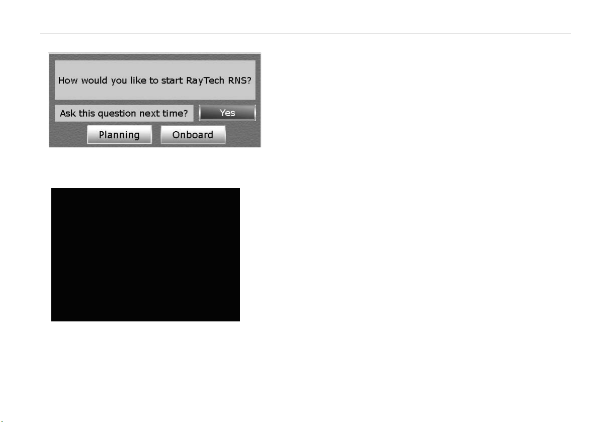
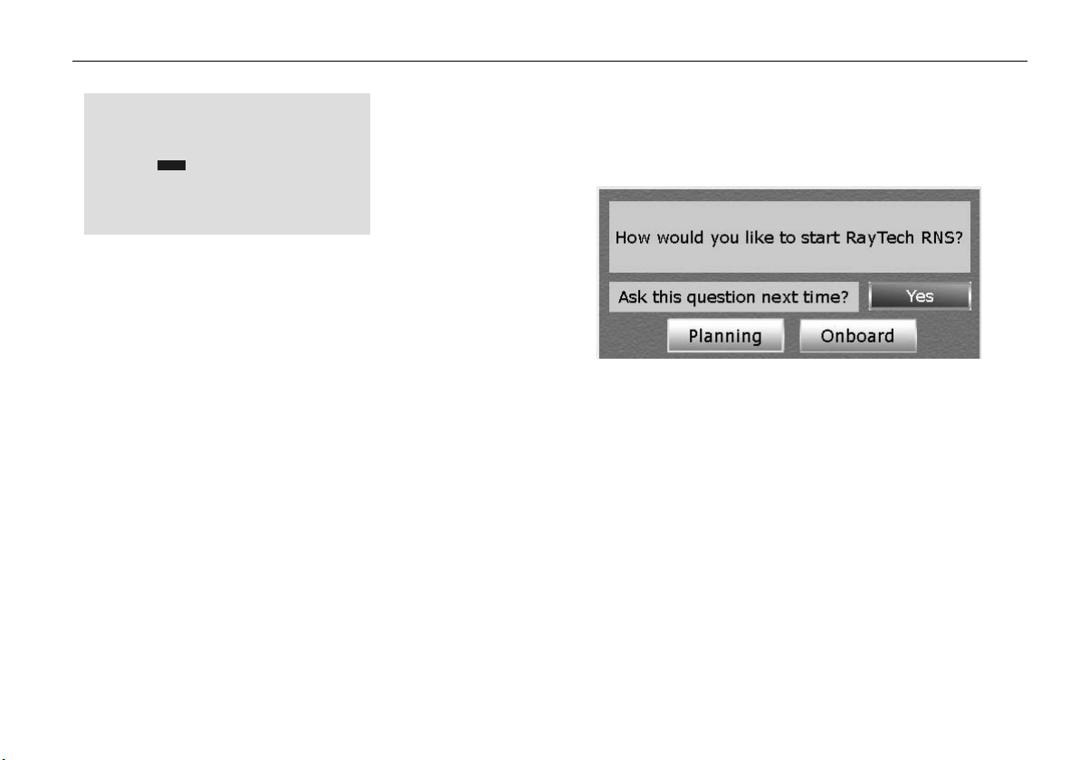
Figure 3-3: RayTech mode dialog box
Figure 3-4: RNS Network Set up Wizard
D6912_1
Entering license key segments of less than 4 characters
You may have a license key that contains segments of less than four
numbers. To enable RayTech it is necessary to enter the license key and
pad the numbers as follows, for example:
Your key is: 600-1-23-456-7-89.
This should be entered as: 0600-0001-0023-0456-0007-0089.
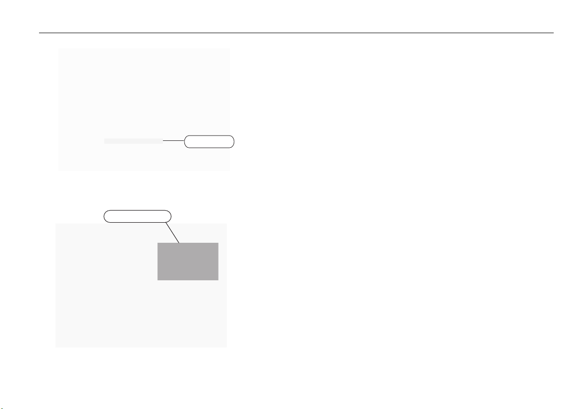
Running RayTech for the first time
To run RayTech for the first time:
1. Select Start/All Programs/Raymarine RayTech Navigator
from the Windows task bar. RayTech will load and the RNS Startup
Wizard is displayed. See
2. Click the button next to the type of license key you want to enter.
Note:
RayTech Planner user’s should skip to section 4.4 and refer to the
Simulator section.
3. Click
Next
. The on-screen keyboard appears. See
For details of license key types refer to “License keys” on page 16.
4. Enter your license key using the on-screen keyboard by moving the
cursor over the required number and clicking.
5. Click Finish. The dialog box closes, and the RayTech splash screen
appears.
The splash screen closes and the RayTech mode dialog box appears “RayTech mode dialog box” on page 17.
You now have a choice of which mode RayTech opens in:
• Planning - Instrument connection is not required - see “Click the soft
key for the mode you want RayTech to open.” on page 19.
• Onboard - enables you to configure your network settings.
Figure 3-1on page 16
Figure 3-2on page 16
Page 28
18 RayTech RNS V6.1 - Users Guide
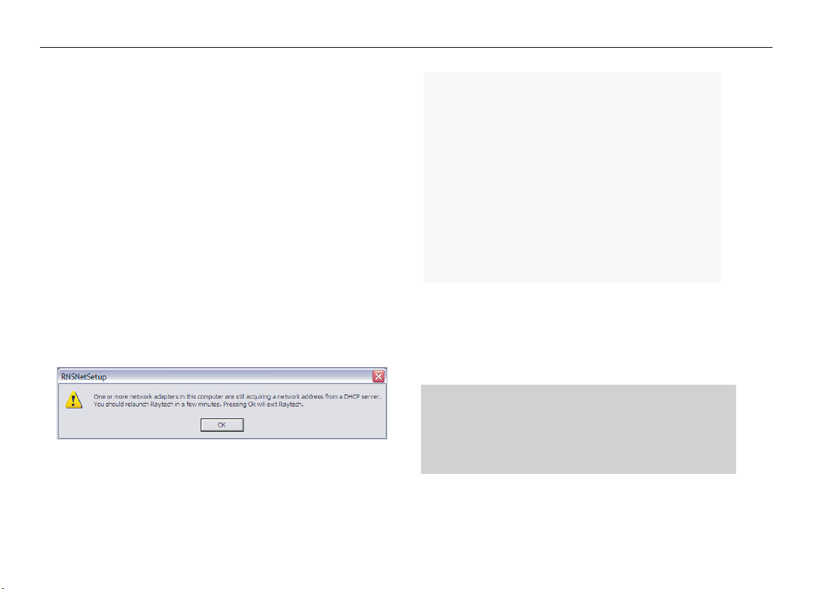
Configure network settings
IMPORTANT: If you do not choose SeaTalk
on which RayTech is running connected to your boats instruments the first
time you run RayTech in Onboard mode. The instruments must also be
switched ON.
Note:
The following section shows how to configure a SeaTalkhs network.
hs,
make sure you have the PC
To configure other types of network click the button next to the
network type and follow the on-screen instructions.
To configure the network settings:
1. Follow Steps 1 through 6 of “Starting to use RayTech” on page 16.
2. Click
Note:
Onboard.
page 17
The RNS Network Setup Wizard appears -
.
Figure 3-4on
If any network adapter is acquiring a network address from a DHCP
server when Raytech is booting into ‘Onboard’ mode the following
message will appear. You should then try to run Raytech once the
network adapter has completed acquiring the necessary network
address.
3. Click the button next to SeaTalkhs (E-Series).
4. Click the button corresponding to whether the PC is currently
connected to your onboard instruments.
5. Click
Next.
The following screen appears:
6. Click the button next to the network card description you wish to use
with RayTech. This card will be configured to talk to your E-Series
display.
7. Click
D10747_1
8. Click
Finish
. The RNSNetSetup dialog box appears.
OK.
RayTech starts to open and the network initialization
progress box appears.
Page 29
Chapter 3: Getting started 19
D9097_1
As the initialization process is carried out RayTech will open and the
Open New Page dialog box is displayed.
9. Highlight the icon for the page type you want to open and click OK.
The new page opens.
10. You can now continue to work in RayTech.
Note:
Raymarine recommends that you register your RayTech software on
the Raymarine website. This ensures that you can recover your
license key in the event of loss or failure of your PC’s hard drive
Using RayTech on a new computer
If you install the upgrade version of RayTech on a new computer, a dialog
box may appear after entering the upgrade key asking you to enter your
original RayTech V3.0/V4.x/V5.0 or V6.x license key. This should be entered
in the same way as before using the on-screen keyboard that appears.
Make sure the license key type is set to the correct version number.
To display the license keyboard:
1. Select File/Setup. The Setup dialog box is displayed.
2. Double-click the License icon. The on-screen license entry keyboard is
displayed.
3. Enter your license key as described in“To run RayTech for the first
time:” on page 17, Steps 7 through 9.
3.4 Continuing To Use RayTech
You will only need to enter a license key number the first time that you use
RayTech after installing it. each time that you open RayTech, the following
dialog box will appear:
D6912_1
Click the soft key for the mode you want RayTech to open.
Operating modes
RayTech can be operated in either of the following modes:
Planning
Enables you to work in a simulated mode, away from your boat if you want
to. Useful for planning and learning purposes.
Onboard
Enables you to work in real-time mode onboard your boat with data being
collected and used from all the instruments that you have connected to
RayTech.
Simulator
RayTech includes a simulator mode which enables you to practise operating the software with simulated data of GPS, Radar, Fishfinder.
Page 30
20 RayTech RNS V6.1 - Users Guide
To Select The Simulator Mode:
1. Select File/setup. The ‘Set Up’ Dialog Box Is displayed.
2. Double-click The
Instruments
Icon. The Instruments Dialog Box Is
displayed.
3. Click The Simulator Icon To set It to the required status.
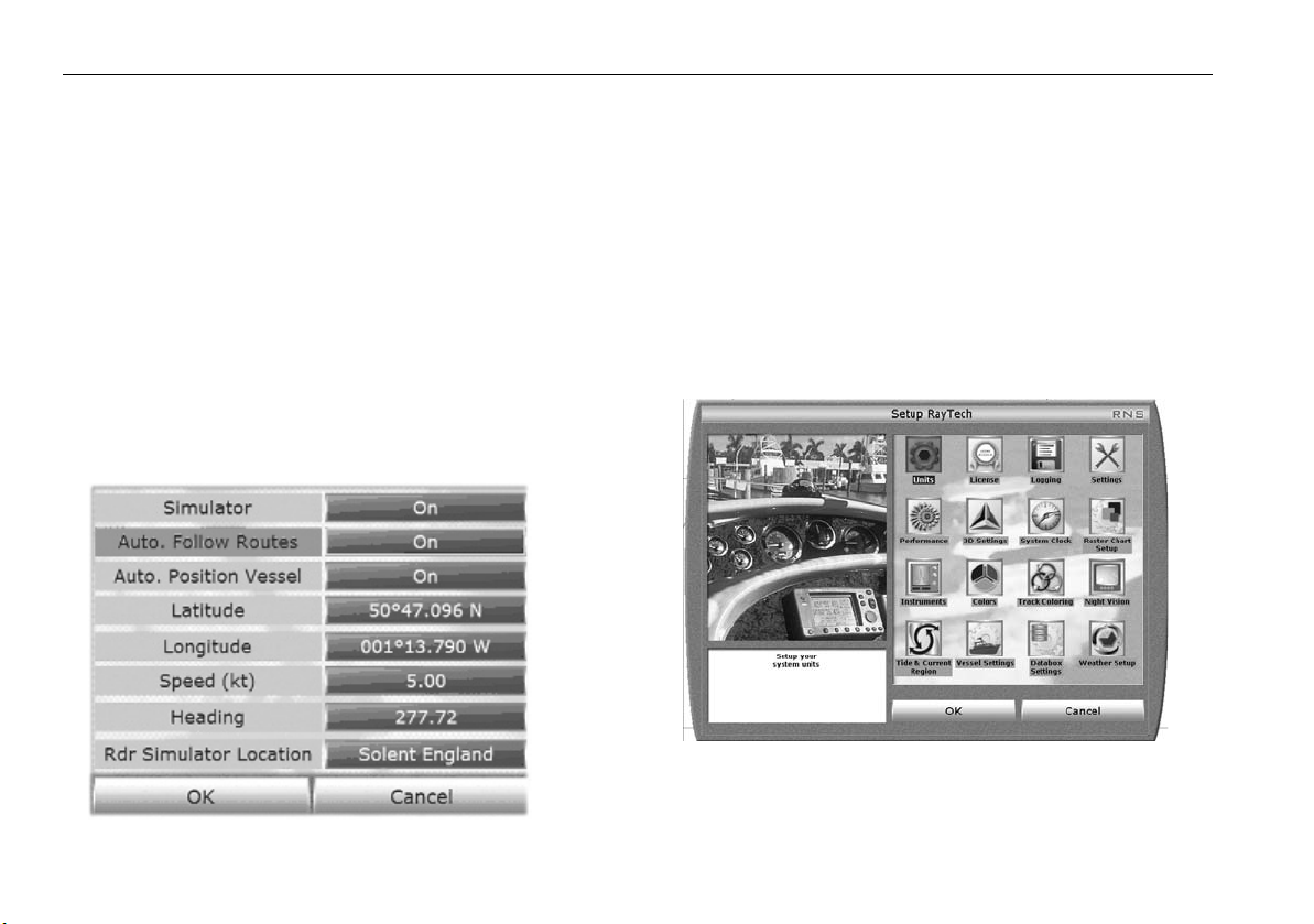
Raytech Planner - Simulate mode.
RayTech Planner only operates in ‘Simulate mode’. If you want to change the Simulator’s automatic settings, you can taylor the menu to suit your needs. The Simulator menu is available to edit:
1. Select File/Setup. The Set Up Dialog Box Is Displayed.
2. Select Instruments.
3. Select Simulator is ON.
4. Taylor the menu to suit your needs/requirements by clicking the
options, as pictured below.
Note:
RayTech must be restarted for these changes to take effect!
The Vessels position can be edited to anywhere in the world, simply Rightmouse click, and select ‘Move Boat Here’ from the drop down menu.
3.5 Setting up RayTech
Once you have installed and started using RayTech, you can enter specific
information for your boat and change default settings to your personal
preferences that suit the way you work.
To set up RayTech:
1. With RayTech running select File/Setup. The set up dialog box is
displayed.
D6915_1
D10912_1
2. Click on the icon of the setting you want to change.
3. Click
OK
. The dialog box for that setting will be displayed.
Page 31

Chapter 3: Getting started 21
4. Click the action boxes and change the settings to your preferred option.
5. Click OK to close the dialog box.
6. Repeat Steps 1 through 5 for each setting you want to customize.
You can customize any of the following settings:
Units configure the units to be used in RayTech
License enter or change license keys
Logging set up your data logging options
Settings set up operational settings
Performance set up system graphics performance settings
3D settings set up general 3D settings
System clock set up the current time and date
Raster chart set up install and control raster charts
Instruments set up RayTech to interface with your instruments
Colors set up the colors displayed in RayTech features
Track coloring set up the display colors for showing tracks
Night vision modes set up how you view RayTech at night
Tides and currents select tide and current regions
Vessel settings set up how your own boat is displayed on screen
Databox settings set up how databoxes and their contents
Weather set up set up how weather information is displayed
3.6 Installing instruments to RayTech
Full functionality of RayTech requires accurate heading and position data
being received from your system instruments. You should refer to “Installation Guidelines” on page 195 for full information on successfully
connecting instruments.
“Running RayTech for the first time” on page 17 describes how to
configure your network and instruments. However, you may at a later date
want to change the way in which instruments are configured to RayTech.
You can choose which way you configure instruments to RayTech. This can
be either:
• Using the RayTech Tools application wizard, or,
• Using the File/Setup/Instruments feature.
RayTech Tools
The RayTech Tools Instrument Configuration wizard can be used to
configure your system instruments.
To use the RayTech Tools wizard:
1. Select Start/Programs/RayTech Tools/RayTech Instrument
Configuration.The Instrument Configuration wizard appears.
2. Click the button next to the network card description and follow the
on-screen instructions as described in “Running RayTech for the first
time” on page 17.
File/Setup/Instruments feature
To configure RayTech and instruments:
1. Select File/Setup. The Setup dialog box is displayed.
2. Highlight the instruments icon and click
dialog box is displayed.
OK.
The configure instruments
Page 32
22 RayTech RNS V6.1 - Users Guide
Network Config
D8909_1
You can now set the network configuration and either automatically or
manually configure your system and instruments.
To set the network configuration:
1. Double-click
Network configuration.
The following dialog box appears.
2. Click OK. The dialog box closes.
3. Use the RayTech Tools wizard to configure the network. For full details
refer to “To use the RayTech Tools wizard:” on page 21.
To automatically configure instruments:
These instructions apply to instruments connected via an RS-232 or RS- 422
connection to your PC.
1.Double-click
tion
. The auto detect progress dialog
Automatic configura-
box is displayed.
2.Click
Cancel
in the Connection
Settings dialog box.
D8910_1
3.When instruments have been
detected an icon is displayed in the dialog box to show connectivity.
Network Config
D8911_1
4. Click Cancel to close the detected COM ports dialog box.
If you want to see what instruments are connected:
i. Double-click the SeaTalk or NMEA icon and the connection dialog
box is displayed.
Page 33

Chapter 3: Getting started 23
ii. Double-click the
What’s connected
icon. The connection dialog box
is displayed showing what instruments are connected and have
been detected.
Note:
This procedure should be carried out if you are using SeaTalkhs and
ST290 instruments and want to show custom channels.
8912_1
To manually configure instruments:
1. Set the network configuration as described in “To set the network
configuration:” on page 22.
2. Double- click
Manual Configuration
. The available Com ports are
displayed.
D8951_1
3. Double-click the COM port you want to configure. The instrument
selection dialog box appears.
D8913_1
4. Scroll down and highlight the required instrument system. Click OK.
5. The selected system is connected and an icon appears in the dialog box
to show connectivity.
Page 34

24 RayTech RNS V6.1 - Users Guide
6. Double-click the NMEA icon and the connection dialog box is
displayed.
7. Double-click the
What’s connected
icon. In the case of NMEA, the
NMEA connection dialog box is displayed.
8. Click either NMEA Sent or NMEA Received icon. The appropriate
sentence dialog box is displayed.
D8914_1
By clicking the action box for the selected NMEA sentence it can be
toggled On or Off.
To display custom channels:
Note:
Custom channels can only be displayed when connected via
SeaTalk and the system includes both an ST290 graphic display and
an ST290 DPU.
1. Set up network configuration and configure instruments as described
in “To set the network configuration:” on page 22 and “To automati-
cally configure instruments:” on page 22 or “To manually configure
instruments:” on page 23.
2. Double-click the
Setting up Instruments
icon. The set up dialog box is
displayed.
3. Double-click
Custom Channels
. The custom channel dialog box is
displayed.
D8915_1
4. Double-click the channel that you want to customize. The channel
selection dialog box is displayed.
Page 35

Chapter 3: Getting started 25
D8952_1
5. Click the action boxes to specify individual settings within that
channel.
6. Click OK. The custom channel is created and can be displayed in a
ST290 databox in the Favorites chapter.
3.7 Installing charts
This section deals with installing the different types of charts that are
compatible with RayTech.
C-MapNT+/PC charts from CD-ROM
IMPORTANT - RayTech must be exited and re-opened before attempting
to install C-Map NT+/PC Selector program. Failure to do so will prevent
your RayTech software from being able to find installed C-Map charts.
To install C-Map charts from a CD-ROM it is necessary to install the C-Map
NT+/PC Chart Selector software onto your PC. This must be installed in
accordance with the instructions on the C-Map software.
Using the C-Map NT+/PC chart selector you select the charts that you want
to install. You then purchase the relevant chart licences on-line and register
them. They are automatically detected by RayTech on start up and are
made available to the RayTech program. C-Map charts are not installed
using the RayTech chart installer.
Note:
RayTech does not support dongled charts. It is recommended using
a USB- C-chart reader instead. This also allows you to use your
charts with a hardware chart plotter as well.
C-Map USB C-Card reader
The USB C-Card Reader must be installed on your PC before you start
RayTech software. Failure to do so will prevent RayTech from being able to
access C-Map charts on C-cards or waypoints or routes that are stored on
the User card.
Charts inserted in the USB C-Card Reader are read in real time as long as
the card is actually inserted in the card reader. C-Map charts cannot be
downloaded to your PC for off-line viewing.
Maptech cartography
Maptech BSB V4.0 cartography
You should install and register Maptech BSB V4.0 cartography in accordance with the installation instructions contained on their software. Failure
to follow the instructions will prevent charts being installed by RayTech.
Earlier Maptech BSB cartography versions.
Versions of Maptech BSB cartography prior to V4.0 do not need to be registered prior to installation using the RayTech chart installer.
Page 36
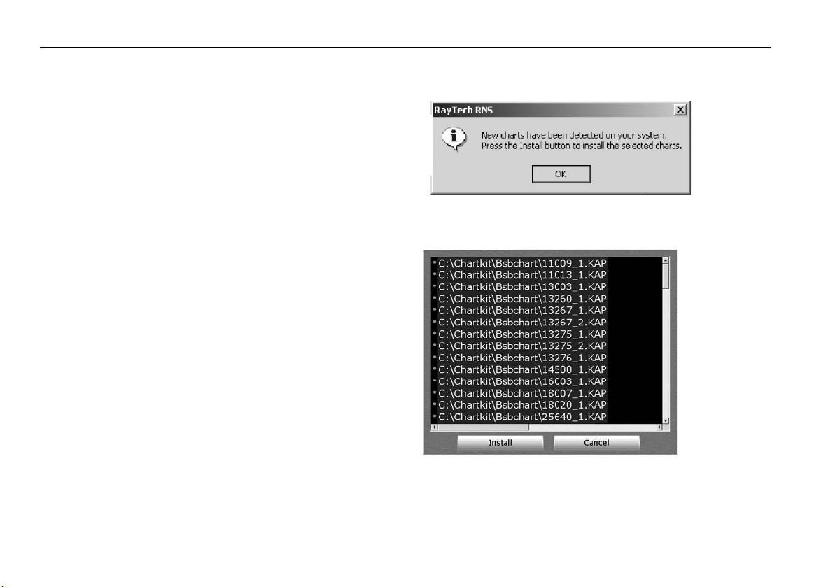
26 RayTech RNS V6.1 - Users Guide
Navionics cartography
There are two ways in which Navionics cartography can be accessed by
RayTech:
• via your SeaTalkhs system.
• using the Navionics multicard reader.
SeaTalk
hs
system
With the PC connected to your SeaTalkhs system, and a Navionics chart
card installed in an E-Series display, open either a new 2D or 3D chart
page. Navionics cartography can then be used with RayTech acting as a
repeater display.
Navionics multicard reader
The Navionics USB multicard reader must be installed on your PC before
you start RayTech software. Failure to do so will prevent RayTech from
being able to access Navionics charts on CF cards or waypoints or routes
that are stored on the User card.
With a Navionics chart card reader installed on the PC that is being used to
operate RayTech, and a Navionics chart card installed you can access Navionics charts.
Charts inserted in the Navionics USB multicard reader are read in real time
as long as the card is actually inserted in the card reader. Navionics charts
cannot be downloaded to your PC for off-line viewing.
RayTech chart installer
The RayTech chart installer is used for installing BSB formatted, raster,
MapTech PCX, photo and topographic charts. It will search and locate
charts that are installed on your system or a CD-ROM. To install charts
using RayTech chart installer:
1. Insert the relevant chart CD into the CD-ROM drive. The New Charts
dialog box is displayed.
D6917_1
2. Click OK. The chart installer selection dialog box is displayed.
All of the charts detected are highlighted by default.
D6918_1
3. Click
Install.
The progress of the installation of each chart will be
shown.
4. The chart installer updates the chart list.
5. Click
OK
. The chart installer selection dialog box closes.
Page 37

Chapter 4: The user interface and controls 27
Chapter 4: The user interface and controls
4.1 Introduction
This chapter introduces the RayTech User Interface and its features and
covers:
• The User Interface.
• The Interface controls.
This chapter gives only a brief overview of the interface and its controls,
experiment, try pointing the cursor at different objects on the screen and
click to see what will happen.
4.2 The screen
You may discover features of RayTech that you didn’t know existed. Experimenting in this way will also help you to find your preferred way of using
RayTech.
To help you get started, left mouse clicks are used to select or initiate
actions. Right mouse clicks display drop-down menus. Holding down the
left mouse button and dragging the mouse diagonally will bound a chart
area. Rotating the mouse wheel will make small setting adjustments or
perform small range changes.
When you open RayTech the default screen - see page 32- will appear
containing:
Title bar
•
•
•
•
- shows the software details.
Drop down menus
Toolbars
- give access to functions of a particular application or mode.
Pathfinder panel
- give access to all the main functions of RayTech.
- shortcuts to RayTech functions:
•
Application display -
displayed.
•
Page selection tabs
those that are open.
•
PC taskbar
•
Power key
exit RayTech.
•
Softkeys
The default screen and controls can be customized to your personal preferences. RayTech will retain these preferences and show them each time you
open it. They can be changed at anytime without closing the program. With
the exception of radar and sonar pages, each page and pane can be independently configured to suit your working practices.
- accesses PC controls.
- press to turn radar transmit on or off. Press and hold to
- used to select function identified by the on-screen label.
area of the screen in which an application is
- Click a tab to display the required page from
4.3 Interface controls
The interface can be controlled using the PC mouse, touchscreen, standard
or Raymarine waterproof USB Navigation Keyboard. This section will detail
how to control the interface using the PC mouse and standard keyboard.
For details on using the Raymarine waterproof USB Navigation Keyboard
refer to page 171 of this manual.
Functions can be accessed via:
• Drop-down menus.
• Toolbars.
•Softkeys.
Page 38
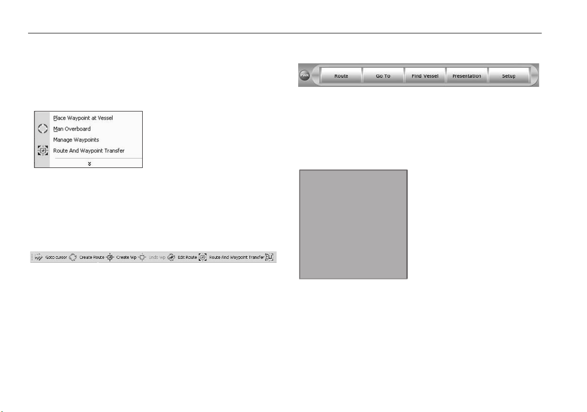
28 RayTech RNS V6.1 - Users Guide
• Right mouse menus.
• Pathfinder panel.
in any combination that you find easiest to use.
Drop down menus
D6920_1
To access functions from the drop-down menus, move the cursor arrow
over the required menu, highlight the function you want to use and click. If
you see downwards pointing arrows at the bottom of a drop-down menu,
this indicates that there are other, less frequently used features available.
Toolbars
Toolbars provide specific shortcuts to a function. To access a function using
a toolbar, move the cursor over the icon for the required function and click.
To display a toolbar:
1. Select View. The toolbar drop-down menu is displayed.
2. Click the toolbar you want to display.
It is checked and the toolbar appears a the top of the screen, below the
drop-down menu bar.
Softkeys
The soft key labels change to reflect the page/pane selected and the functions available. Click the corresponding soft key to select the required
function. When you have finished using a function or making adjustments,
click BACK to return to the previous level of softkeys.
Right mouse menus
Clicking the right mouse button
will display a menu of functions for
a particular object such as a mark,
waypoint or chart object. Virtually
any object on the RayTech screen
will present a specific menu of
functions when you place the
cursor over it and click the right
mouse button. This is a very fast
way to find the function that you
D6923_1
want (even if you don’t know
exactly what it is), because you will see only those functions which are
appropriate for the object at which you are pointing.
Page 39

Chapter 4: The user interface and controls 29
Pathfinder panel
The Pathfinder panel provides shortcuts for some of the more common
functions. Just move the cursor over the required button and click. The
controls that can be found in this panel are:
use to scroll through open pages
changes the active pane in a split page
displays the waypoint softkeys
(if the function bar is open)
displays the databox softkeys
(if the function bar is open)
displays the setup softkeys (if the function bar is open)
zooms the page
to show a larger (OUT), or smaller (IN) area.
changes radar range
D6925_1
4.4 Displaying information
Information is shown in databoxes or dialog boxes on the RayTech screen.
The different types of information boxes are illustrated in the following
section:
Selection dialog box
A selection dialog box allows you to access various components to carry
out a selected function or feature setting.
Select File > SetUp.
D6915_1
To make a selection from the box, either click the icon you wish to access
then click OK, or double-click the icon.
Page 40
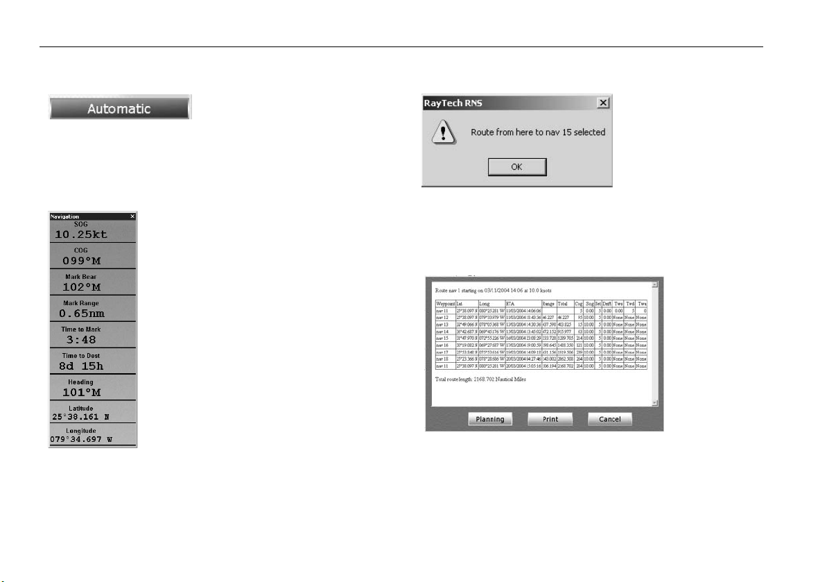
30 RayTech RNS V6.1 - Users Guide
Action box
Action boxes are contained in a
D6924_1
selection dialog box and change a
parameter. Click an action box to
cycle through settings, or cause a drop-down menu or on-screen keyboard
to be displayed, allowing you to change the parameter as required.
Data box
A databox displays information dedicated to a
specific function, such as, navigation, VRM/
EBL’s. Because it displays dedicated information,
the contents of the box are updated in real time.
Databoxes can be floated, moved to any position
and then docked. They can be resized, just like a
databox in any Windows program. They can be
opened and closed as required.
D6926_1
Alert and information dialog box
An alert and information
dialog box informs you
that something has
happened within the application that needs your
approval, or tells you that
D6928_1
you need to select an
option, usually ‘Yes’ or ‘No’. Once you have accepted the option, the dialog
box is automatically removed from the screen.
Application information box
Application information boxes contain information about various functions,
such as route details.
D6927_1
Page 41

Chapter 4: The user interface and controls 31
3
1
2
2
3
1
2
2
4.5 Changing what you see on the screen
You can show more than one application on a page. RayTech contains preset page options for displaying up to three applications on a page, each in
a separate pane. There is also a custom option that allows you to split a
page either horizontally or vertically and display a different application in
each pane:
D6929_1
To open a pre-set page:
1. Select File/Open New Page. The Open New Page dialog box is
displayed.
2. Click on the pre-set page layout required.
3. Click OK. The new page will open in the selected layout.
To open new custom page:
1. Select File/Open New Page. The Open New Page dialog box is
displayed.
2. Click Custom.
3. Click OK. A new blank page will open with the application icons
displayed.
4. Double click the icon for the application you want to open. The application will open in a full page format.
5. Right click on the page status bar and select Split Horizontally/
Split Vertically.
6. Click the split style you require.
7. The open application will move to the bottom pane (horizontal split),
or to the right hand pane (vertical split). The application icons will
appear in the new pane.
8. Double click the required application icon to open it in the pane.
Moving around a split page
When you open a page that has been split you need to be able to activate a
different pane within the page.
The pane that you are working in is known as the ‘active’ pane, and has a
blue border around the edge of it.
The softkeys displayed in the function bar are the top level softkeys for that
application. To make another pane active within a page, click the ACTIVE
button on the Pathfinder panel. The blue border will move to the next
pane and the softkeys will change to the top level for that application. To
change the active pane, just click the ACTIVE button until the application
you want to work in is highlighted.
Page 42

32 RayTech RNS V6.1 - Users Guide
Title bar
Drop-down menus
Toolbars
Databoxes
Page selection tabs
PC taskbar
RayTech default screen
Power
soft key
Pathfinder
panel
Application
display area
D8749_1
Soft keys
Page 43

Chapter 5: Using charts 33
Chapter 5: Using charts
5.1 Introduction
RayTech utilizes chart layering technology, which permits you to simultaneously view different types of charts and maps, including navigational
charts, live radar, aerial photographs and weather data.
For full information on installing charts refer to Chapter 2 - Getting Started.
Use your charts safely
CAUTION: RayTech should not be used as a substitute for good
navigational practice nor for official government charts.
Until you are familiar with interpreting the chart display, you should take
every opportunity to compare displayed objects with visual targets, such as
buoys and coastal structures. You should practice harbor and coastal navigation during daylight and in clear weather conditions. RayTech simulator
mode will also help you gain experience.
5.2 The chart screen
The chart is a digitized image of the paper chart for the selected area - see
“RayTech default screen” on page 32. The chart shows objects, such as
landmasses, navigational objects and depth contours.
The amount of detail shown varies for different chart types and areas
covered. The scale at which the chart is shown also affects the amount of
detail shown. Cartographic information is also available for objects marked
on the chart. Source details for such objects as structures, lines and open
sea areas are also available. Using the advanced functions described in
Chapter 7 - Using RayTech’s Advanced features, information on the
weather, tides and currents can be overlaid on the charts.
When connected to a heading data source you can also overlay the radar
image on to the chart.
5.3 Opening a chart
To open a chart for the first time:
1. Click File/Open New Page. The open new page dialog box is
displayed.
D8751_1
2. Highlight the page type that you want to open (Navionics, C-Map or
raster).
3. Click OK.
Page 44

34 RayTech RNS V6.1 - Users Guide
5.4 Moving around the chart
You can move around the chart using:
Chart panning
RayTech includes chart panning. Whenever you move the cursor near the
edge of a chart page and click, the chart will move in that direction. You
can also use the arrow keys on the keyboard to pan the chart.
Click over an object or position on a chart and the chart page or pane will
center on the location of the cursor.
Zooming
The are a number of ways to change the range, or zoom in and out of a
chart to see more or less of a given area.
Range In will show a smaller area of a chart, Range Out will show a
larger area of a chart. You can use:
Menu Item Select Tools/ Range In or Range Out.
Keyboard Press
Pathfinder panel Click the upper portion of the RANGE key to zoom
Left mouse button Click and hold the left mouse button. As you drag the
Right mouse button When you right click on a chart, the right click menu is
tab
to zoom in, or
out, or the lower portion to zoom in.
mouse, the selected area will be highlighted in gray.
Release the button and the selected area will be
zoomed in.
displayed. Select Range In or Range Out.
Shift + tab
to zoom out.
Finding your boat on the chart
Now that you have opened a chart, you will need to know where you are.
Your boat is displayed using a boat shaped icon.
To find your current position on the chart:
Find Vessel
Click
The page or pane will automatically pan and the boat’s position will be
centered on the screen.
The page or pane will remain centered until you click the screen. The chart
will then re-center on the cursor’s location.
in the standard toolbar, or the
Find vessel
soft key.
5.5 Choosing a chart type
You choose the type of chart you want to display using the charting
toolbar.
There are four primary buttons on the toolbar for controlling the type of
chart being displayed. These are:
• Raster charts.
• Vector (Navionics or C-Map).
• PhotoCharts Overlay (Navionics or raster).
• Topo Charts.
There is also a button to enable or disable radar overlay, and a button to
enable or disable chart quilting.
Note:
RayTech will use raster photos over Navionics photos when both
layers have been turned on.
Page 45

Chapter 5: Using charts 35
To select the chart type to be displayed:
Click the button for the type of chart you want to be displayed. The button
will highlight to indicate that chart type has been selected.
If there is no chart type enabled, or charts are unavailable at the level of
zoom that has been selected, only an aquamarine colored background will
be visible. You can either select a chart type from the toolbar, or adjust the
zoom level, using the range buttons, until the chart is visible.
Chart layers
If you have multiple chart buttons enabled at the same time, then your
chart is layered. This means that one type of cartography is superimposed
on top of one or more other types of cartography.
All charting layers, except Navionics and C-Map, have a transparency
control which allows you to increase or decrease a layers transparency.
Each page or pane will default to it’s full transparency level when it is first
opened.
Down
arrow
To adjust layer transparency:
1. Click the down arrow at the right of the chart type. The transparency slider is
displayed.
2. Move the cursor over the transparency slider.
Transparency
slider
i.To make the layer more opaque, place the cursor over the right of the transparency slider and click. The value increases.
ii. To make the layer more transparent, place the cursor over the left of
the transparency slider and right-click. The value decreases.
D8753_1
20% level40% level
Chart order
In order for chart layering to work consistently, charts have been layered in
a pre-determined order.
• Your chart pages are layered as follows from bottom to top:
• Vector charts - Navionics or C-Map.
• Raster Navigational charts.
• Raster topographic charts.
• Raster or Navionics aerial photography charts.
• Radar overlay.*
• Orbimage Satellite Sea Temperature.**
• Orbimage Satellite Plankton.**
Page 46

36 RayTech RNS V6.1 - Users Guide
• GRIB weather data.***
Notes:
1. * Only available if RayTech is connected to an hsb2 radar or E-
Series display and receiving a heading input.
2. ** Accessed from fishing toolbar.
3. *** Accessed from weather toolbar.
The order of layers cannot be changed. If you are having trouble viewing a
chart layer, try switching off all of the other layers on the charting toolbar
until the background appears aquamarine. Then click the button of the
chart type you want to view, and the cartography will appear.
Chart quilting
When you are working with raster format navigation charts, the Quilting
button allows you the option of using a single chart image, or seamless
charting.
With quilting enabled, the system default for any opened chart window,
RayTech stitches together all of your raster cartography, connecting the
edges of the different charts together. This means that no manual intervention is required to switch charts. You simply pan to the area you wish to
see. Chart detail will be affected as you range in or out to view larger or
smaller scales.
When you are using the quilting function, the best available chart for the
area you are in will always be displayed. This information is based on your
boat’s position, the focal point of the cursor and the range scale selected.
As you pan or zoom around the chart, cartography will be continuously
displayed.
With quilting turned off, the chart at the focus of the display will be shown
alone. The scanned edges of the chart containing the latitude and longi-
tude scales, notes and chart numbers will become visible and all adjacent
charts will be hidden from view. Zooming in or out will cause the chart to
be enlarged or reduced in size.
Page 47

Chapter 5: Using charts 37
Status bar
Navigational object
Page tab
Boat icon
Cursor
Cartographic
information
available
Depth contour
Default chart screen
Page 48

38 RayTech RNS V6.1 - Users Guide
Page 49

Chapter 6: Using Platinum cartography 39
Chapter 6: Using Platinum cartography
6.1 Introduction
The Navionics Platinum Chart card used in conjunction with RayTech
enables you to access enhanced 2D cartography and 3D bathymetric
charts.
These features will give you an accurate, easy to view image of the area
around your boat, giving you confidence in knowing where you are and
what is around you, enabling you to plan in detail where you want to go.
Operation of these charts and their features is similar to the way in which
existing chart cards are used.
2D cartography
The Platinum chart card enhances many of the chart features found on
other Navionics chart cards and introduces new ones making additional
features available.
Enhanced features
• Additional business services information - enabling you to find local
restaurants, shops and places of interest in addition to marina services.
• Additional wrecks data - a new set of wrecks and their associated data.
• Major coastal roads - can now be displayed on a 2D chart.
• US inland waterways - enables you to view major navigable lakes, e.g.
Great Lakes, Lake Okeechobee.
New features
• Panoramic photos - for many ports and marinas on the chart.
• Pilot book information - an on-screen version of almanac information
for many ports.
• Aerial photo overlay - enabling you to overlay the on-screen chart with
an aerial image of coastal waters and land, making it easier to identify
objects and cartographic features.
3D bathymetric charts
The 3D bathymetric chart application introduces an easy-to-use chart
format that provides a graphical view of land and sea contours around your
boat. Much of the information available on a conventional chart can be
shown in three dimensions, giving you an accurate, easy-to-view image of
the area around your boat that can help you plan:
• Fishing spots.
• What fishing pattern to use.
•Safe routes.
If you are in a new area or visibility is poor, 3D cartography can help to give
you the confidence to know where you are and what is around you. You
can also show active waypoints and routes on a 3D chart.
3D cartography has the following features:
• Choice of operating modes - Active or planning.
• Ability to change the view point.
o
• 360
• Vertical exaggeration of the view.
• Ability to view water depth.
• Ability to indicate the area which your fishfinder transducer cone
• Ability to overlay Navionics aerial photographs.
rotation of the selected view.
covers (if fitted).
Page 50

40 RayTech RNS V6.1 - Users Guide
6.2 New 2D chart features
The new 2D features of the Navionics Platinum chart card include:
• Aerial photo overlay.
• Panoramic photos.
• Pilot book information.
All of these chart features are accessed using the normal controls and soft-
keys of RayTech.
Aerial photo overlay
The aerial photo overlay will enables you to overlay the on-screen chart
with an aerial image of coastal waters and land, making it easier to identify
objects and cartographic features. Depending on the area that your chart
covers the aerial overlay is either full color or black and white. The level of
features and objects shown also varies dependent on the area covered.
You can adjust the level of visibility between the chart and the aerial
photograph.
To display aerial photo overlay:
In the Charting toolbar click Navionics Photos. Aerial photo overlay will
now be displayed.
Panoramic photos
Panoramic photos are now available for many ports and marinas, enabling
you to see what the area looks like, especially valuable if you have not
visited this area before.
7923_1
The aerial photograph covers navigable waters and up to 3 miles inland
from the coast.
D8755_1
Page 51

Chapter 6: Using Platinum cartography 41
The availability of these photos is shown by a camera symbol
on the chart. The symbol is placed where the photo was taken
and the angle of the shot is shown by the angle of the camera
symbol.
To view a panoramic photo:
1. Right click on the camera icon and select
Navionics Object Properties
The information dialog box appears.
2. Click Show Photo.The photo is shown in the dialog box.
Pilot book
The pilot book is an on-screen version of a nautical almanac and contains
navigational information about ports and marinas.
To view the pilot book:
1. On a Navionics chart page, right-click the port services icon. The rightmouse menu is displayed.
2. Select Navionics Object Properties. The information dialog box is
displayed.
.
3. Highlight the pilot book page reference. The Show Pilot Book soft key
is displayed.
4. Click Show Pilot Book. The pilot book opens in a new page.
Use the scroll bar at the right to scroll through the available information.
Page 52
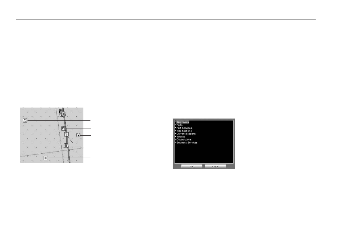
42 RayTech RNS V6.1 - Users Guide
6.3 2D chart enhancements
The enhancements to 2D charts include the following:
• Additional business services information.
• Additional wrecks data.
• Major coastal roads.
• US inland waterways.
Business services information
The updated business services information enables you to view information such as name, address, telephone number of selected businesses and
information on places of interest by selecting an on-screen icon.
Service station
Boat dealership
Restaurant
Hairdressers
Bank
D8756_1
To display business services:
Select the appropriate symbol on the chart and right click. The information
will be displayed in a dialog box.
Doctors
• Waypoint.
• Port or Port Services.
• Tides and currents station.
• Wrecks and obstructions.
• Business services.
To use the find nearest feature:
In an area that is covered by a Navionics chart:
1. Right-click anywhere on a Navionics chart page. The right-mouse
menu is displayed.
2. Select
Navionics Object properties
. The Information dialog box is
displayed.
3. Click Find Nearest. The find nearest selection box is displayed.
D8757_1
4. Highlight the category you want to view.
5. Click OK. The information is displayed in the information dialog box.
Find nearest
The Find Nearest feature provides information to enable you to find the
nearest:
Page 53
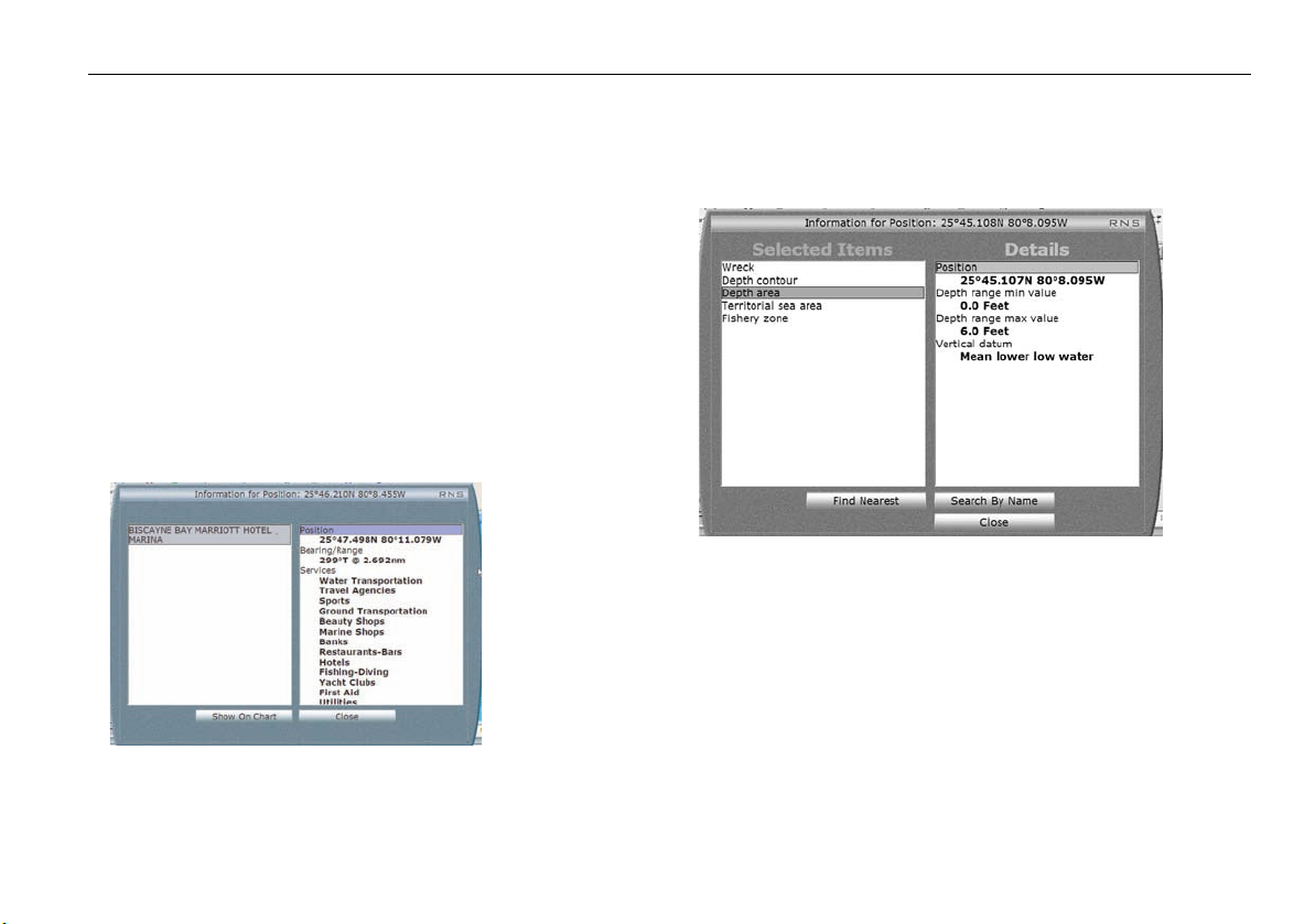
Chapter 6: Using Platinum cartography 43
Search port by name
The Search port by Name feature enables you to search for a specific port.
However, it will not enable you to search for a specific restaurant or chandlery name within a port.
To search by name:
In an area that is covered by a Navionics chart:
1. Right-click in the required area. The right-mouse menu is displayed.
2. Select
Navionics Object properties
displayed.
3. Click Search by Name. The on-screen keyboard is displayed.
4. Enter the name of the port you want to locate.
5. Click OK. The on-screen keyboard closes and the result(s) are displayed
in the information dialog box.
. The Information dialog box is
Wrecks data
Wrecks data provides details of wrecks that can also be found on a paper
chart.
D8758_1
To display wrecks data:
1. Right click the wreck icon. The right mouse drop-down menu is
displayed.
2. Highlight Navionics Chart Object.
3. Click OK. The Wrecks information dialog box is displayed.
Page 54
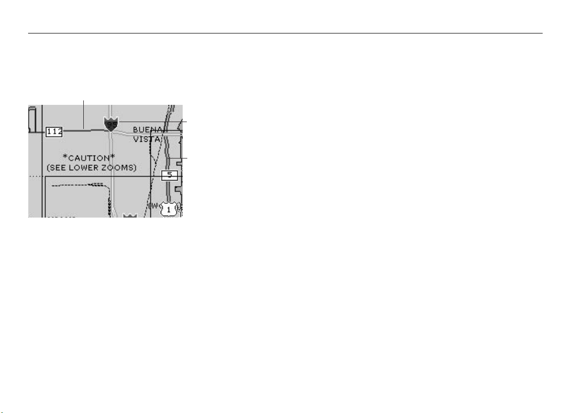
44 RayTech RNS V6.1 - Users Guide
Coastal roads
When you display a chart with an aerial photo overlay major coastal interstate, state highways and other major roads are shown.
Highway/ Minor road
Interstate highway/ Motorway
State highway/ Major road
D8759_1
The ability to view roads depends upon the level of transparency that has
been selected for the aerial overlay. As the overlay visibility is decreased
the roads will fade from view.
US inland waterways
Chart coverage of major US inland waterways such as the Great Lakes and
Lake Okeechobee are now included in Platinum cartography.
Page 55

Chapter 6: Using Platinum cartography 45
6.4 3D bathymetric chart application
Status bar
North arrow
Navigational object
Boat symbol
3D cartography screen
Land mass
Underwater contours
D8760_1
Page 56

46 RayTech RNS V6.1 - Users Guide
The application
To obtain the best results from your 3D cartography you should make sure
that RayTech is receiving accurate heading and position data.
The 3D application - see “3D cartography screen” on page 45 - is opened
on a new page of RayTech which can be full screen or part of a page set.
Whichever way you choose to view the 3D chart, the window will always
show a status bar and a display area
Status bar
The status bar appears across the top of the 3D chart and contains the
following information:
• Range - this is the horizontal distance across the screen and is
displayed in the selected system units.
• Mode - shows the mode in which the application is working.
• Rotation - shows in degrees true how far the on-screen view has
been rotated from your boats heading.
Display area
The display area shows the following information:
• North arrow - gives a 3D indication of True North in relation to the
chart view (cannot be turned off).
• Boat symbol - can be shown as a power or sail boat to indicate your
position n the chart.
• Depth scale - shows the approximate depth below your boat (accurate depth information should be obtained from another source on
your system).
• Cartographic objects - shows navigation marks, wrecks etc.
.
The controls
Your 3D chart is operated in a similar way to a 2D chart using the appropriate soft keys and the mouse.
The operating modes
You can choose to operate the 3D chart in one of the following modes:
• Active motion mode.
• Planning mode.
Active motion mode
This is the default mode when you open the 3D application and there is a
valid fix. The screen shows an aerial view of the 3D chart from a position
above and slightly behind your boat looking forward. This position is the
eye-point. As your boat moves forward the chart automatically updates
and reveals the changing view ahead.
Changing the view
In active motion mode there are four view options that you can choose
from:
•Forward.
•Aft.
•Port.
• Starboard.
With each view the eye-point is changed to show a different area of the
chart.
To change the viewpoint:
1. Click
2. Click
3. Click
Presentation
3D View Options
View to
.
.
until the required view is displayed.
Page 57
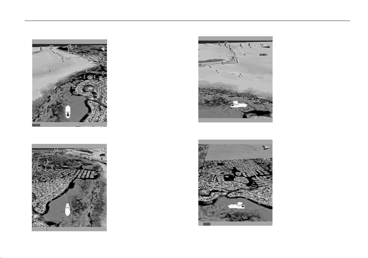
Chapter 6: Using Platinum cartography 47
Forward
FWD
Aft
2.431nm
FWD ROTATE 195oT2.431nm
AFT ROTATE 011oT
Default view.
Eye point is above and
behind the boat, looking
forward.
Click
Find Ship
to return to
this view.
D8761_1
Eye point above and in front
of the boat, looking behind
it.
Port
AFTPRT
Starboard
PRT ROTATE 106oT2.431nm
Eye point above and to starboard side of boat, looking
to port.
D8763_1
STB ROTATE 280oT2.431nm
Eye point above and to port
side of the boat, looking to
starboard.
AFT
D8762_1
STB
AFT
D8764_1
Page 58

48 RayTech RNS V6.1 - Users Guide
Changing your viewpoint
Softkeys
You can change your view of the chart using the following softkeys:
• Rotate On - enables you to choose which point on the screen the
chart will move around.
• Eye - rotates the chart around the eye-point, maintaining a rela-
tive position to the on-screen boat.
• Center - rotates the chart around the center-of-view on the chart.
• Adjust - enables you to choose how you change the view.
• Rotate - enables you to rotate the chart view through 360
want to maintain a view from a particular angle, rotate the chart
until you see the required view. The chart will automatically
update.
• Pitch - enables you to change the angle at which you view the
chart. This can be from sea level to a full aerial view. You cannot
view the chart from underwater.
• Find Ship - pressing this soft key at any time enables you to return to
the default action motion mode chart view.
• Presentation - enables you to view additional features.
Chart offset
The 3D chart center can be offset in a similar way to a 2D chart. You can
offset the position of the on-screen boat by 1/3 or 2/3 from the center-ofview towards the edge of the window. This has the effect of making more
of the 3D chart visible without changing the selected range.
o
. If you
Making the view clearer
There are two ways in which you can make your chart view clearer:
• Exaggeration.
• Declutter.
Exaggeration
Sometimes it is easier to see a topographic feature on the chart by making
it more obvious., for example, this could be particularly helpful while
fishing.
Using the exaggeration feature of the 3D chart to vertically stretch objects
on the chart can achieve this making it easier to see an objects shape and
position. You can exaggerate the chart between a factor of 1 and 50 using
the Adjust Exaggeration soft key.
Declutter
Navigating in an area that shows a lot of information on the chart, such as
navigation marks, can be confusing. Depending on your chart view level it
can make features or even your own position difficult to see. The declutter
feature helps to reduce this confusion and make the chart clearer, by
removing some objects from view.
Planning mode
Planning mode enables you to view an area of the chart, different to the
one in which you are navigating. To enter planning mode, pan to the area
of the chart that you want to view. Using the right-mouse menu select,
Move Boat here
All of the functions that are available in active motion mode are available
in planning mode and control of the chart is the same. However, the mode
. Active motion mode is automatically suspended.
Page 59

Chapter 6: Using Platinum cartography 49
information in the status bar is now shown in brackets to indicate planning
mode has ben selected.
Clicking the FIND SHIP soft key reTurns the application to active motion
mode, in the default view, showing the chart in the forward looking view
at your current position.
Using 2D and 3D charts together
If the area in which you are navigating is unfamiliar to you, or visibility is
poor, working with 2D and 3D chart applications on the screen side by side
can give you extra confidence and help you to find out what is around you.
With your RayTech page set up to view the two applications together a
comprehensive view of the surrounding area is show.
As with all multiple page sets the active window is indicated by a red
border. To make any changes in an application it must be the active
window.
Navigating with 3D Charts
To navigate to a new waypoint or use a new route, you should first create
the waypoint or route on your 2D chart.
Once navigation is activated in the normal way, the 3D chart displays:
• The active waypoint using the same symbol as the 2D chart.
However, it should be remembered that a route can only be edited using a
2D chart. Any changes that you make on the 2D chart are automatically
shown on the 3D chart.
Page 60

50 RayTech RNS V6.1 - Users Guide
Navionics Platinum cartography
D8754_1
Page 61

Chapter 7: Working with waypoints 51
Chapter 7: Working with waypoints
7.1 Introduction
Waypoints are a core feature of RayTech. They can be created while any
application is active and used by the others. They can be stored in the
system, e-mailed, archived to a memory card, or transferred to another
SeaTalk, hsb
2
or NMEA compatible instrument.
7.2 What is a waypoint?
A waypoint is a position marked on a chart, radar or sonar screen as a
reference point or as a place to go. Waypoints are represented on screen by
a symbol and their details stored in a dedicated waypoints list.
7.3 Placing a waypoint
A waypoint can be placed:
• at the cursor position
• at the boat’s position.
• at a known position.
All waypoints can be used in creating routes. When waypoints are placed
they are given a default symbol, you can change this default if required refer to “Changing a waypoint symbol” on page 53.
Note:
When using RayTech as part of an integrated system, waypoints
should be named in accordance with the parameters set by your
GPS/chartplotter display.
...at the cursor’s current position
To place a waypoint at the cursor’s current position:
1. Select Waypoint/Place Waypoint at Cursor.
2. Move the cursor to where you want to place the waypoint.
3. Click and a new waypoint will appear in the selected position.
... at the boat’s current position
To place a waypoint at the boat’s current position:
1. Select Waypoint/Place Waypoint at Vessel.
2. A new waypoint will be placed at the boat’s current position.
... at a known position
There are two ways that you can place a waypoint at a known position:
• using the Enter Waypoint (EW) button.
• using the Manage Waypoints function.
Enter Waypoint button
To place a waypoint at a known position using the Enter
Waypoint button:
1. Click the Enter Waypoint button on the toolbar. The on-screen
keyboard is displayed.
2. Enter the name of the new waypoint.
3. Click OK. The on-screen keyboard closes and the waypoint properties
dialog box appears.
The Enter Waypoint can be found on the
Waypoints and Routes toolbar.
Page 62

52 RayTech RNS V6.1 - Users Guide
• Enter details for the waypoint as described in Steps 6 through 10 of
“To place a waypoint at a known position using the Manage Waypoint
function:” on page 52
Manage waypoint function
To place a waypoint at a known position using the Manage
Waypoint function:
1. Select Waypoints/ Manage Waypoints. The folders dialog box
will appear.
2. Select the waypoint folder in which you want to locate the new
waypoint. Click
3. Select
New Waypoint
4. Enter the name for your new waypoint. Click OK. The waypoint properties dialog box appears.
OK
.
. Click OK. The on-screen keyboard appears.
D6932_1
D6937_1
5. Click
Latitude
. The on-screen numeric pad appears.
D6934_1
6. Enter correct latitude. Click OK. The keypad closes.
7. Click
8. Enter correct longitude. Click
9. Click
Longitude
OK
. The on-screen numeric pad appears.
OK
. The keypad closes.
. The waypoint properties dialog box disappears and a new
waypoint is placed at the position specified.
Page 63

Chapter 7: Working with waypoints 53
7.4 Placing a man overboard marker
In the unfortunate event that a member of crew, or an important piece of
equipment falls overboard, a man overboard (MOB) marker can be used to
mark the position. If a MOB marker is placed, RayTech suspends all current
navigation functions, calculates the most direct route back to the marker,
and automatically makes that the active route.
To place a MOB marker:
Any of the following actions will place a MOB marker:
•Select Waypoint/Man Overboard.
•Click the MOB icon in the standard toolbar.
•Click WAYPT on the Pathfinder panel. Click
To cancel a MOB marker:
1. Select Waypoints/Manage Waypoints.
2. Double-click the
3. Right-click the
4. Highlight
MOB
folder icon. The MOB folder is displayed.
MOB
icon. The right-mouse menu is displayed.
Delete
and click. The MOB marker is deleted.
Man Overboard
softkey.
7.5 Changing a waypoint symbol
You can change a waypoint symbol from the default to any of 36 options.
D8765_1
To change a waypoint symbol:
1. Select Waypoints/Manage Waypoints. The folders selection
dialog box is displayed.
2. Highlight the folder that contains the waypoint that you want to
change.
3. Click
4. Highlight the required waypoint.
5. Click
6. Click the icon action box. A drop-down menu is displayed.
7. Highlight the symbol you want to represent the waypoint.
8. Click
9. Click
OK
. The waypoints contained in that folder are displayed.
OK
. The waypoint properties selection dialog box for that
waypoint is displayed.
OK
. The waypoint symbol is changed to your selection.
OK
. Repeat Steps 4 through 8 until you have changed all the
waypoints you want to change.
Page 64

54 RayTech RNS V6.1 - Users Guide
7.6 Navigating to a waypoint
You can navigate to an existing waypoint at any time using:
• Waypoints button the Pathfinder panel.
• Using the cursor.
• Using the waypoints database list.
...using the WAYPT button
1. Click WAYPT on the Pathfinder panel.
2. Click
3. Click
4. Click required folder.
5. Click
6. Click required waypoint.
7. Click
8. Click OK.
...using the cursor
1. Place the cursor over the waypoint you want to go to.
2. Right-click. the right mouse menu is displayed.
3. Click
More
softkey on the function bar
Go to Waypoint
OK
.
OK
. The waypoint is selected and the waypoint selected dialog
box appears.
Go To (name of waypoint)
. Waypoint dialog box appears.
D6928_1
.
...using the waypoints list
1. Click
2. Highlight the folder the waypoint appears in and click
3. Click the waypoint you want to go to.
4. Click
5. Click OK.
Go To Waypoint.
OK
. The route dialog box closes and the waypoint dialog box
appears.
The route dialog box appears.
OK
.
D6940_1
7.7 Moving a waypoint
You can move a waypoint to a new position, or to your boat’s current
position.
To move a waypoint to a new position:
1. Place the cursor over the waypoint you want to move.
2. Press and hold the left mouse button.
3. Move the cursor to the position on the chart where you want the
waypoint moved to, then release the button. The waypoint will move
to the new location.
To move a waypoint that you are
boat’s current position:
Select Waypoint/ Move Destination to Vessel. The waypoint that
you are approaching is moved to your boat’s current position.
heading toward
to your
Page 65
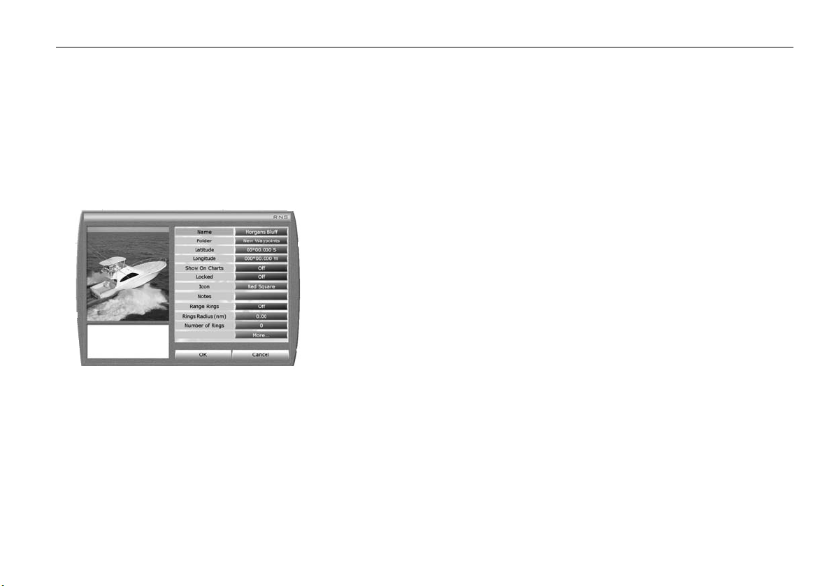
Chapter 7: Working with waypoints 55
To move a waypoint you are
boat’s current position:
Select Waypoint/Move Origin to Vessel. The waypoint you are
heading away from is moved to your boat’s current position.
heading away from
to your
7.8 Edit waypoint details
You can change how, where and when any waypoint is displayed by
editing the Waypoint properties dialog box.
To edit a waypoints details:
1. Place the cursor over the waypoint that you want to edit.
2. Right click to display the right-mouse menu.
3. Select and click
box for the selected waypoint is displayed.
4. Select and click on the details that you want to edit. The on-screen
keyboard, numeric pad or drop-down lists will be displayed as
required.
Waypoint Properties
D6937_1
. The waypoint properties dialog
5. Click
Note:
OK
when you have finished editing the waypoint details. The
dialog box closes.
C-Series software greater than v3.18 and E-series software greater
than v3.22 include a feature requiring that all Waypoint and Route
names start with a letter, and not a number.
7.9 Organizing waypoints
You can create as many different groups, known in RayTech as folders, of
waypoints as you need, and then manipulate the individual waypoints
within those folders. Waypoint folders can be added, deleted or renamed
just like individual waypoints. You can also swap waypoints between
folders, and send them to and retrieve them from the waypoint recycle bin.
To create a new waypoint folder:
1. Select Waypoint/Manage Waypoints. The Folders dialog box is
displayed.
2. Click
3. Type in the name for the new folder. Click
To add a waypoint to a folder:
1. Select Waypoints /Manage Waypoints. The Folders dialog box is
2. Open the folder that contains the waypoint you want to add to a new
3. Double-click the required waypoint. The waypoint properties dialog
4. Click the
5. Highlight the folder that you want to put the waypoint in. Click
6. The waypoint is added to that folder.
New Folder
created.
displayed.
folder. The waypoints in that folder are displayed.
box is displayed.
list is displayed.
. The on-screen keyboard is displayed.
OK
. The new folder is
Folder
action box. A drop-down menu displaying the folder
OK
.
Page 66

56 RayTech RNS V6.1 - Users Guide
7. Click OK. The waypoint dialog box closes.
8. Repeat steps 1 through 7 above until you have added all the required
waypoints to the new folder.
To rename a folder:
1. Select Waypoints/Manage Waypoints. The Folders dialog box is
displayed.
2. Right-click the folder that you want to rename. A drop-down menu is
displayed
3. Highlight Rename and click. The on-screen keyboard is displayed.
4. Type in the new name of the folder. Click
OK
. The folder is renamed.
7.10 Deleting a waypoint or waypoint folder?
To delete a waypoint on-screen:
1. Place the cursor over the waypoint you want to delete.
2. Right click. The right mouse menu will be displayed.
3. Select
4. The waypoint is removed from the chart.
To delete a waypoint using the waypoint list:
1. Select Waypoints/Manage Waypoints. The folders selection
2. Highlight the folder you want to delete the waypoint from.
3. Right click. The All waypoints in folder selection dialog box is
4. Right click the waypoint you want to delete. A drop-down menu is
5. Highlight
6. Click
Delete Waypoint
dialog box is displayed.
displayed.
displayed.
Delete
.
OK
. The waypoint is deleted and the selection dialog box closes.
and click.
To delete a waypoint folder:
1. Select Waypoints/Manage Waypoints. The folders selection
dialog box is displayed.
2. Highlight the folder you want to delete.
3. Right click the waypoint folder you want to delete. A drop-down menu
is displayed.
4. Highlight
5. Click
closes.
Delete
.
OK
. The waypoint folder is deleted and the selection dialog box
7.11 Waypoint recycle bin
When you delete waypoints, they are placed in the waypoint recycle bin,
from which you can later retrieve them if you need to. However, it is important to remember that each time you close RayTech the recycle bin is
emptied, permanently deleting all the waypoints it contains.
To retrieve waypoints from the recycle bin:
1. Select Waypoints/Manage Waypoints. The Folders dialog box is
displayed.
2. Highlight
3. Click
4. Highlight and double-click the first waypoint that you want to retrieve.
The waypoint dialog properties box is displayed.
5. Click the
6. Highlight the folder that you want the retrieved waypoint to be placed
in.
7. Click
placed in the selected folder.
8. Repeat Steps 1 through 7 for additional waypoints to be retrieved.
9. Click
Waypoint Recycle Bin
OK
. The contents of the recycle bin will be displayed.
Folders
action box. A drop-down menu is displayed.
OK
. The waypoint is removed from the waypoint recycle bin and
OK
. Folders dialog box closes.
.
Page 67

Chapter 7: Working with waypoints 57
To manually empty the recycle bin:
1. Select Waypoints/Empty Waypoint Recycle Bin. A dialog box is
displayed asking you to confirm this action.
2. Click
Note:
OK
. The recycle bin will be emptied.
It is important to remember that each time RayTech is closed, the
recycle bin is emptied automatically, permanently deleting all the waypoints it
contains.
7.12 Transferring route and waypoint data
Route and waypoint data can be transferred both to and from RayTech.
There are several methods that you can use to transfer route and waypoint
data. The method that you use will depend on the links that are available,
these can be:
• Network - enables the transfer of data using any of the following
protocols:
• SeaTalkhs.
2
•hsb
.
•NMEA.
Note:
If you want to transfer data using hsb2 or NMEA protocols, your
chartplotter should be configured to receive this data. For full
details of configuring your display refer to the relevant manufacturer’s handbook.
• Removable card - enables the transfer of data using any of the
following card types:
• C/E-Series or A65 via CompactFlash card.
• Pathfinder Plus (RL, RC, SL) displays via C-Map User Card.
• RC400 or RC435 via CompactFlash card.
• File - enables the transfer of data using any of the following file types:
• Excel file.
• Comma delimited file.
• Raymarine Waypoint file.
• C/E-Series file format.
• e-mail - enables the transfer of data using your e-mail client.
To transfer route and waypoint data:
D8769_1
1. Click
Import/Export Routes and Waypoints
. The import/export dialog
box appears.
D8766_1
2. Click the relevant button for the function you want to complete.
The method of importing or exporting data follows the same proce-
dures, the difference is in the dialog box wording. For ease of explanation the following examples show the export dialog boxes.
3. Click
Next.
The Export Routes and Waypoints dialog box appears.
Page 68
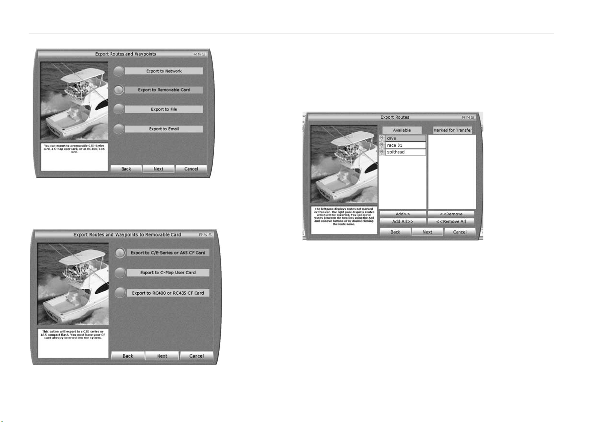
58 RayTech RNS V6.1 - Users Guide
D8767_1
4. Click the button for the required method of data transfer.
5. Click
Next
. The method selection dialog box appears.
6. Click the required option for transferring all or selected routes and
waypoints. If you choose to transfer selected data only, the Export
Routes dialog box appears.
The left hand pane displays routes not marked for transfer. The right
hand pane displays routes which will be exported.
D8770_1
Routes can be moved between the two lists by using the
Remove
buttons, or by double-clicking the route name.
7. Click
Next
. The Export Waypoint Folders dialog box is displayed.
Add
or
The left pane displays waypoint folders not marked for transfer, the
right pane displays waypoint folders which will be exported. You can
move waypoint folders between the two lists using the
Add
or
Remove
buttons, or by double-clicking the waypoint folder.
D8768_1
Page 69
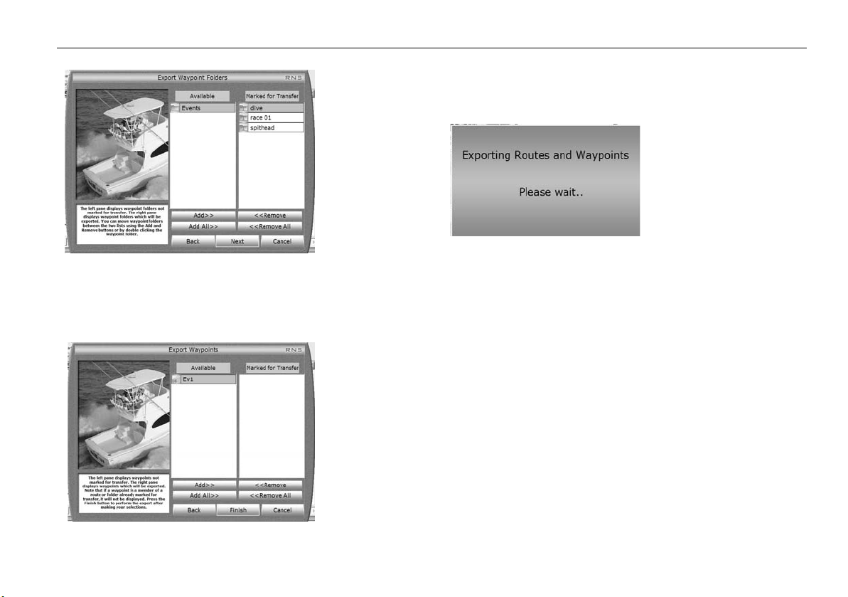
Chapter 7: Working with waypoints 59
D8823_1
8. Click Next. The Export Waypoints dialog box is displayed.
The left pane displays waypoints not marked for transfer. The right
pane displays waypoints which will be exported.
If a waypoint is a member of a route or folder already marked for transfer, it will not be displayed.
9. Click Finish. The Export progress box dialog box is displayed.
D8771_1
D8824_1
Page 70

60 RayTech RNS V6.1 - Users Guide
Page 71
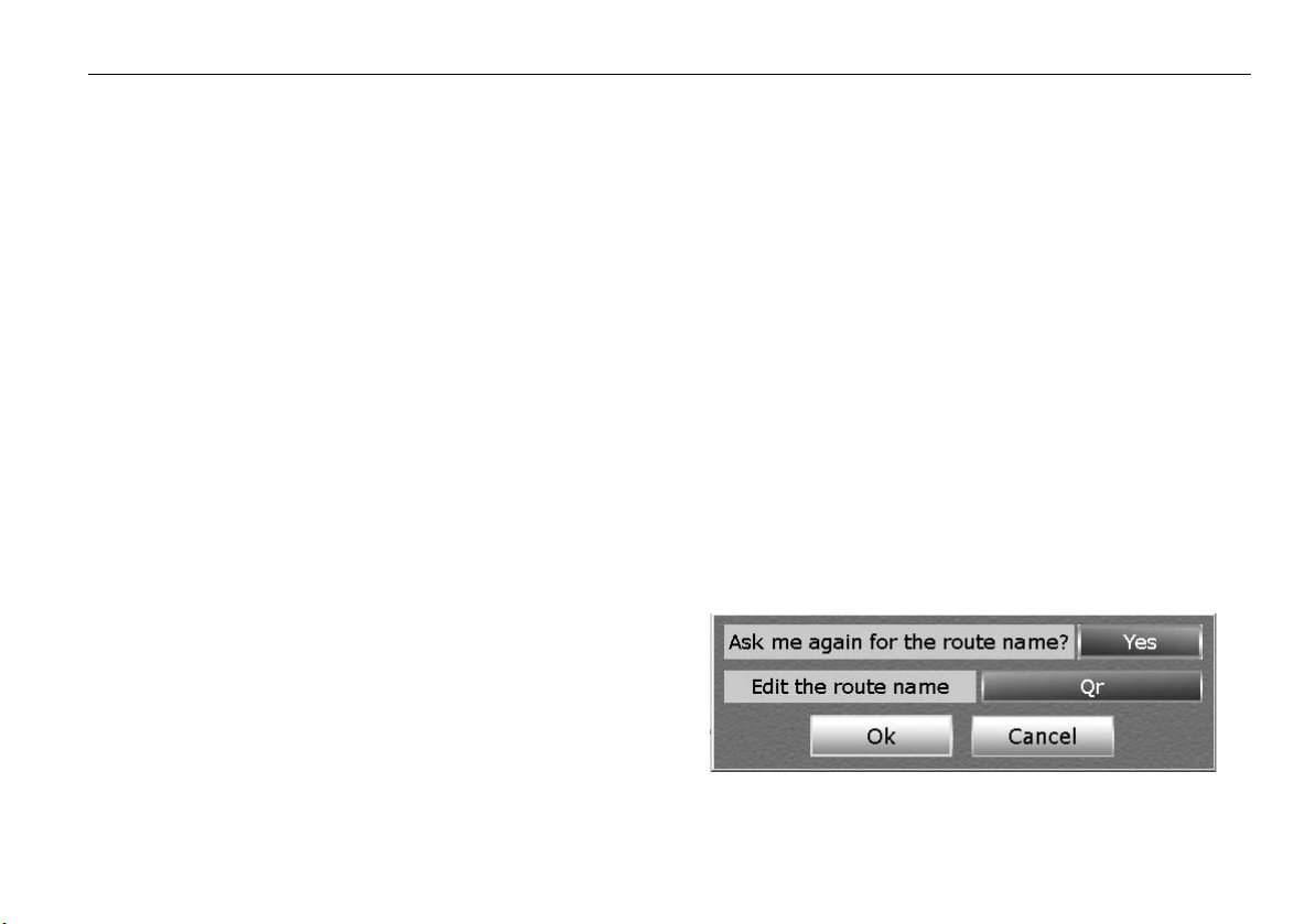
Chapter 8: Working with routes 61
Chapter 8: Working with routes
8.1 Introduction
This chapter explains how to use RayTech to chart and plot courses. It is
intended to have you navigating in the shortest time possible and covers:
• Creating routes.
• Editing routes.
• Monitoring a course.
The definition of terms used in working with charts and routes will be
found in Appendix A - Charts.
8.2 What is a route?
A route is a path from location A to location B, and is composed of a series
of waypoints that you place on a displayed chart. Each waypoint represents
a certain position along the path of a route. A route typically has a starting
waypoint, an ending waypoint, and as many intermediate waypoints as
you need or want.
The imaginary line between two waypoints is known as a leg. The leg of a
route that your boat is currently traveling is called the active leg. An active
leg consists of an origin waypoint (the waypoint that you have just
departed) and a destination waypoint (the waypoint you are moving
towards). In RayTech, the active leg of a route is represented by a dashed
line, and the destination waypoint blinking.
Plotting a route can be achieved with just a few mouse clicks and you can
easily edit the route after placing it on screen. Routes can be as simple or
as complex as you need, and customized for easy recognition and navigation. RayTech stores all of your favorite or most commonly used routes, and
you can create several back-up routes for any destination, should inclement
weather or other circumstances dictate you take a different course.
If you have RayTech connected to your GPS and autopilot, the route you
chart on the screen can be run automatically.
8.3 Creating a route
You create a route by placing a series of waypoints between your starting
point and your destination. Each waypoint represents a certain position
along the path of a route.
Note:
When using RayTech as part of an integrated system, routes should
be named and the number of waypoints used should be in accordance with the parameters set by your GPS/chartplotter display.
To create a route:
1. Click
2. Click
Route
. The route softkeys are displayed.
Create Route
. The Quick route dialog box is displayed.
D6986_1
Page 72
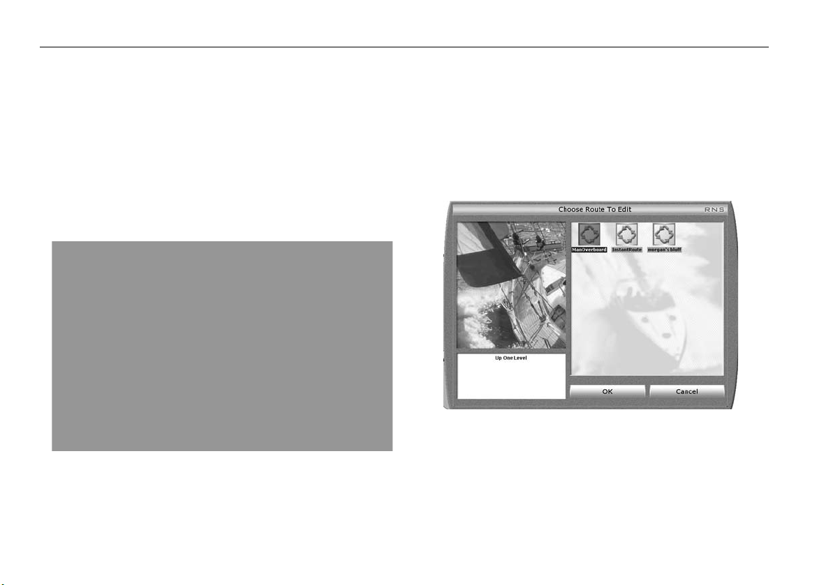
62 RayTech RNS V6.1 - Users Guide
3. Click OK to accept the default name of Qr, or click
name
to enter your own. The on-screen keyboard is displayed.
Edit the route
4. Type in a name (up to 16 characters including spaces) for your route.
5. Click
OK
. The dialog box closes.
6. Move the cursor over the area where you want the route to begin.
7. Click the mouse.
8. The route is started. and the name you have chosen along with the
range and bearing of the first leg is displayed.
9. Draw the route you want to take. Click at each point you want to place
a waypoint.
D8825_1
Add a waypoint to a route
There are two ways that you can add a waypoint to a route:
• using the Routes menu.
• using the right mouse menu.
To add a waypoint using the route menu:
1. Select Routes/Edit Route. The Choose Route to Edit dialog box is
displayed.
D6935_1
2. Highlight the route you want to edit. Click OK. The Editing Route
dialog box for the selected route is displayed.
10. When you have placed all the waypoints in the route, right click.
11. The right-mouse menu is displayed.
12. Click
Finish Route
. The route is finished.
Page 73
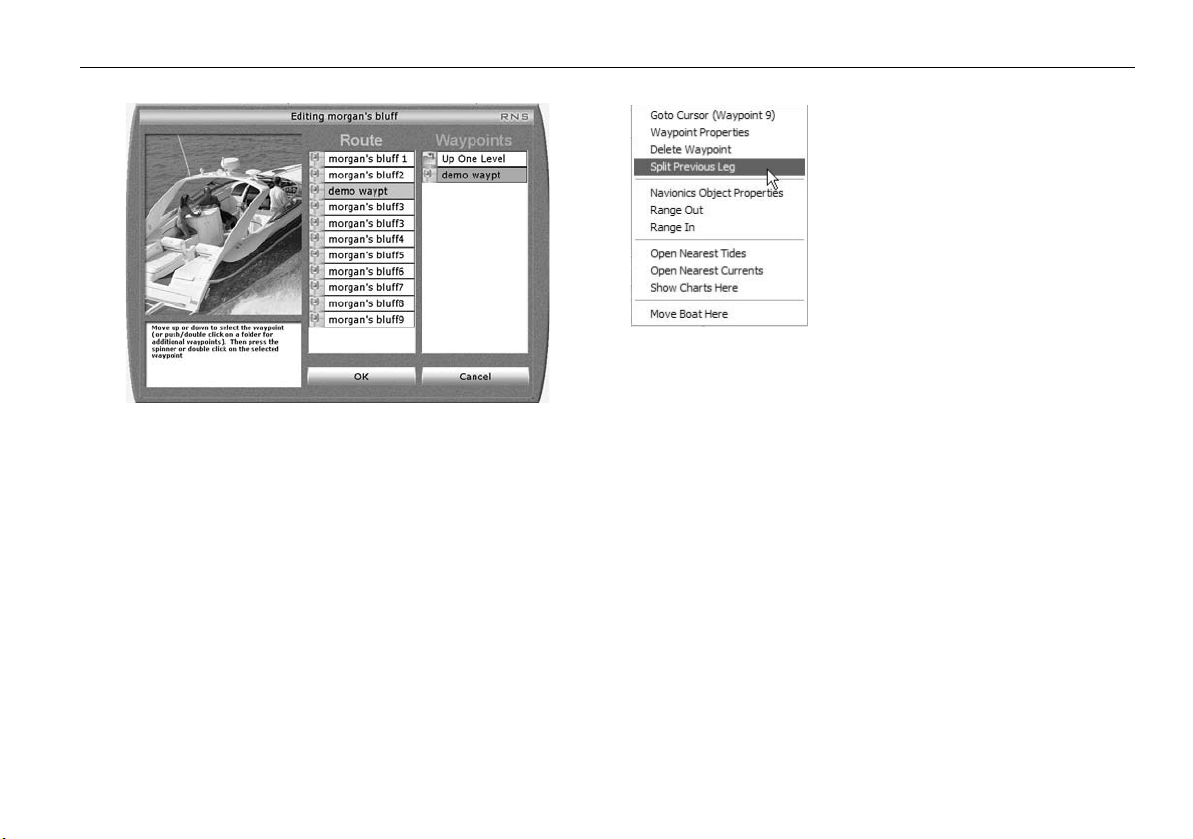
Chapter 8: Working with routes 63
D6936_1
3. In the Route column, highlight where you want to add a waypoint.
4. In the Waypoints column highlight the waypoint or mark you want to
add to the route.
5. Double-click the highlighted waypoint or mark. It will be added to the
route below the highlighted waypoint.
To add a waypoint to a route using the right-mouse menu:
With the route displayed
1. Place the mouse over the target waypoint for the end of the leg that
you want to place the new waypoint in.
2. Right click the waypoint. The right click menu is displayed.
D8826_1
3. Scroll down and highlight
Split Previous Leg
.
A new waypoint will be placed in the center of the previous leg of the
route.
4. Place the cursor over the new waypoint.
5. Click and hold the left mouse button.
You can now move the waypoint and drag it into position with the
mouse.
Deleting a waypoint
To delete a waypoint from a route using the right mouse
menu:
1. Place the cursor over the waypoint you want to delete and right click.
The right mouse menu is displayed.
2. Select Delete Waypoint. The waypoint is deleted, the route and route
leg information is updated.
Page 74

64 RayTech RNS V6.1 - Users Guide
To delete a Waypoint using the waypoint list:
1. Select Waypoints/Manage Waypoints. The waypoint folders
selection dialog box is displayed.
2. Highlight the folder you want to delete the waypoint from.
3. Right click. The All Waypoints in folder dialog box is displayed.
4. Right click the waypoint you want to delete. a drop-down menu is
displayed.
5. Highlight
6. Click
Delete
.
OK
. The waypoint is deleted and the dialog box closes.
Choosing a route
With a chart page open:
To choose a route:
1. Click
2. Double-click the route you want displayed. The selected route is
Route/Choose Route
displayed on screen and automatically followed.
RayTech includes a setting to enable or disable the Follow Route
option.
. The Choose Route dialog box is displayed.
Following route
With a chart page open and a route displayed:
To follow a route:
1. Click
2. Toggle
3. Engage the autopilot after carrying out the normal safety checks.
Route
. The next level of softkeys is displayed.
Follow Route
to On. The autopilot will alarm.
To follow a route ‘from here’:
With a chart page open and a route displayed, either
1. Toggle Follow Route to OFF.
2. Place the cursor over the waypoint you want to which you want to
travel.
3. Right click. The right mouse menu is displayed.
4. Click
5. Toggle
Go to Cursor
Follow Route
selected waypoint.
. The waypoint name is displayed in brackets.
to On. The route will be followed from the
8.4 Monitoring the course
With RayTech receiving accurate heading and position information, you
can use the Course Deviation Indicator (CDI) - see “CDI monitor” on
page 66 to monitor your course and accurately steer to a target waypoint.
The CDI gives a graphical representation of your boat’s course in a ‘rolling
road’ format.The symbol for your boat is shown on the centerline when the
boat is on course, with steering instructions for maintaining your course
shown just above the screen horizon.
As you travel towards the target waypoint, the grid representing the sea,
will move down the screen at a rate proportional to your boat’s speed.
Your target waypoint is located on the centerline of the display over the
screen horizon. As the distance to the target waypoint decreases, the
waypoint symbol will appear on the horizon and start to move down the
screen. The waypoint symbol will blink on and off and it’s name is
displayed to the right as it travels down the screen. Information on your
boat’s course is displayed above the screen horizon to indicate:
• Target - waypoint name.
• Speed Over Ground (SOG) - displayed in knot.
Page 75

Chapter 8: Working with routes 65
• Range to target waypoint - displayed in nautical miles (nm).
• Course Over Ground (COG) - displayed in degrees magnetic.
• Bearing to target waypoint - displayed in degrees magnetic.
• Cross Track Error (XTE) - displayed in nm.
The XTE also gives instructions as to which way you should steer to correct
the error. These instructions are shown as arrows either side of the XTE
pointing towards the centerline. The greater the XTE, the more arrows are
shown. You should correct your course by steering in the direction indicated by the arrows.
The CDI can be displayed on its own page or as part of a custom page with
other applications. MARPA targets can also be displayed on a CDI page.
Restart XTE
CDI’s Restart XTE function gives you the option, if selected to re-center the
boat within the CDI window, zeroing all the XTE data.
Next Leg and Previous Leg
Next Leg and Previous Leg are functions available to allow you to select the
waypoint (within a route) you are aiming at while completing a ‘GOTO’. By
selecting the ‘Next Leg’ you select the next waypoint in the route you
have selected. By selecting ‘Previous Leg’ you revert to a previous
waypoint in the selected route.
Page 76

66 RayTech RNS V6.1 - Users Guide
CDI monitor
D6988_1
Page 77

Chapter 9: Using tides and currents 67
Chapter 9: Using tides and currents
CAUTION: Tides and currents
Whilst every effort is made to ensure the accuracy of the
data used for tides and currents, this information can be
influenced by local conditions. It is therefore recommended
that consideration is given to obtaining accurate local information wherever possible
9.1 Introduction
Tide and current data is available for many areas on the chart application
of RayTech.
The predictions displayed for Tides and Currents are sufficiently accurate
under moderate weather conditions, for the coastal areas served by the
reference station, to be used for navigation planning. However, certain
weather fronts and storms can alter tidal patterns and influence predicted
times and heights.
In addition and in common with all similar products, tidal data is calculated
algorithmically and may, in some regions, be subject to error. If exact tidal
heights or times are critical to a particular passage, Raymarine recommends that details are checked against a Tidal Almanac published by the
appropriate marine authority.
Setting the region
To make sure that the correct tide and current information is displayed, you
must set the region in which you are operating.
To set the tide region:
1. Select File/New Page/Tides. A new page will open showing the
default tide information.
2. Click
3. Click
4. Scroll and highlight the required area. Click OK. The area is now set to
5. Repeat Steps 1 through 4 replacing Tides with Currents to set the
Presentation
Region
that selected.
correct region.
.
. The region dialog box is displayed.
Page 78

68 RayTech RNS V6.1 - Users Guide
9.2 Tides
Tide height data - see page 62 - is a prediction for maximum and minimum
tide heights over a 24 hour period for a selected station in a selected
region.Data for sunrise and sunset is also provided.
As long as you have a valid global positioning system (GPS) time /date
signal being received by RayTech, the graph will automatically default to
showing today’s tides. If there is no signal then the graph will default to an
earlier date.
Some regions have non-sinusoidal tide patterns, with distorted or multiple
high and low water peaks and troughs. In such regions, it is better to refer
to the graph to determine high and low water times and heights rather
than using the textual description above the graph.
Open nearest tides
The open nearest tides feature enables you to access tidal information from
the tide station nearest to a selected position.
To use Open Nearest Tides:
1. Right click in an area of the chart. The right-mouse menu is displayed.
2. Click Open Nearest Tides. The tidal information for the tide station
nearest your selected position will be displayed in a new page.
To display tidal height information for stations other than
the nearest:
1. Open a new page to display Tides.
2. Select View/Tides and Currents Toolbar.
3. Click Select Station. The station name dialog box is displayed.
D8773_1
4. Use the cursor to select the required station name and highlight it.
5. Click OK. The station name dialog box closes and tidal information for
the selected station is displayed.
6. Click Select Date. The on-screen calendar is displayed.
7. Use the cursor and forward and back arrows to select the correct
month.
8. Use the cursor to select the required date.
9. Click OK. The tidal information is updated.
Page 79

Chapter 9: Using tides and currents 69
9.3 Currents
Current flow data is a prediction for maximum and minimum current flow
over a 24 hour period for a selected station. Data for sunrise, sunset and
moon phase is also provided.
When using current information the default is always the last selected
station. As long as there is a valid GPS time/date signal being received by
RayTech, the graph will automatically default to show today’s currents. If
there is no valid signal the graph will default to an earlier date.
Open nearest currents
The open nearest tides feature enables you to access tidal information from
the tide station nearest to a selected position.
To use Open Nearest Currents:
1. Right click in an area of the chart. The right-mouse menu is displayed.
2. Click Open Nearest Currents. The current information for the current
station nearest your selected position will be displayed in a new page.
To display current flow information for stations other than
the nearest:
1. Open a new page to display Currents.
2. Select View/Tides and Currents Toolbar.
3. Click Select Station. The station name dialog box is displayed.
D8773_1
4. Use the cursor to select the required station name and highlight it.
5. Click OK. The station name dialog box closes and current flow information for the selected station is displayed.
6. Click Select Date. The on-screen calendar is displayed.
D8774_1
7. Use the cursor and forward and back arrows to select the correct
month.
8. Use the cursor to select the required date.
9. Click OK. The current flow information is updated.
Page 80
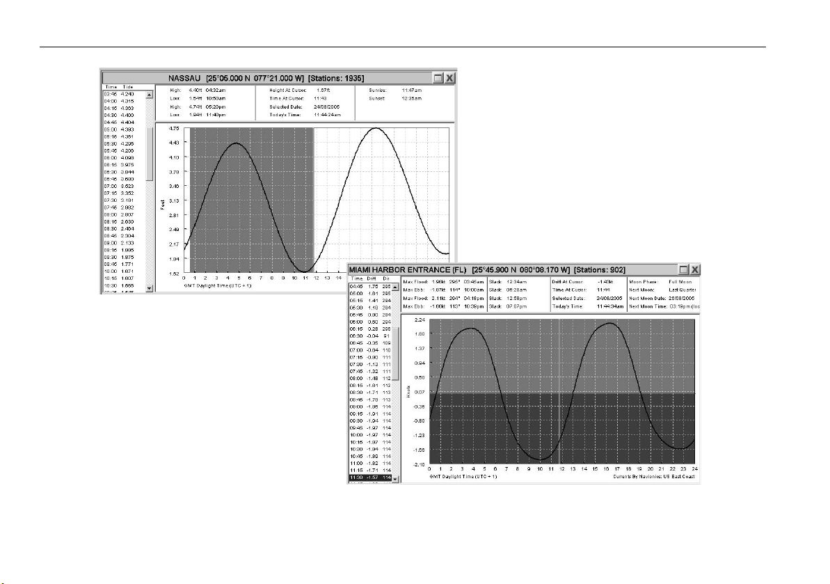
70 RayTech RNS V6.1 - Users Guide
Currents
Tides
Tides and Currents screens
D8772_1
Page 81

Chapter 10: Working with radar (Analog) 71
Chapter 10: Working with radar (Analog)
10.1 Introduction
Data from your hsb2 series Pathfinder and SeaTalkhs E-Series radar can be
transferred and displayed (repeated) within RayTech. The picture can be
displayed on a separate page or you can overlay a radar image on a chart.
This chapter explains how to use the radar application of RayTech to find
out what is around you and to assist in collision avoidance and includes:
• Setting up the radar display.
• Getting the best radar picture.
• Using waypoints to mark position.
• Collision avoidance using VRM/EBLs and MARPA.
• Overlaying a radar image on a chart.
For technical information on radar refer to Appendix B -Radar.
Full functionality of the radar application requires heading and position
data. A fast heading sensor is also needed for operating the Mini Automatic Radar Plotting Aid (MARPA) functions and radar/chart overlay.
Until you are familiar with interpreting the radar display, you should take
every opportunity to compare the radar’s display patterns with visual
targets such as other boats, buoys, and coastal structures. You should practice harbor and coastal navigation during daylight and in clear weather
conditions.
10.2 Displaying radar in a new page
To display radar in a new page:
1. Select FILE/Open New Page. The Open New Page dialog box will
appear.
2. Double- click the
display in standby mode.
3. From the soft key bar, click the PWR button.
4. Click
Radar Transmit
hsb2 or SeaTalkhs network and displayed on the screen.
RADAR
icon. The radar page will open with the
to ON. The radar data will be repeated over the
10.3 The radar picture
With your radar scanner connected and the radar in transmit mode, the
radar picture provides a map-like representation of the area in which the
radar is operating.
Typically your boat’s position is at the center of the display, and its dead
ahead bearing is indicated by a heading line, known as the Ship’s Heading
Marker (SHM).
On-screen targets may be large, small, bright or faint, dependent upon the
size of the object, its orientation and surface. Be aware that the size of a
target on-screen is dependent on many factors and may not necessarily be
proportional to its physical size. Nearby objects may appear to be the same
size as distant, larger objects. With experience, the approximate size of
different objects can be determined by the relative size and brightness of
the echoes.
Page 82

72 RayTech RNS V6.1 - Users Guide
10.4 Changing how the radar picture is shown
The radar picture can be shown in one of three modes:
Head - up (H-UP)
Head -up is the default mode. The radar picture is shown with the boat’s
current heading upwards. As the heading changes the picture will rotate.
North - up (N-UP)
In this mode, the radar picture is stabilized and shown with North at the
top of the picture. As your boat changes its heading, the SHM will move
accordingly.This mode requires heading data input.
Course - up (C-UP)
In this mode the radar picture is stabilized and shown with your current
course upwards. As your boat’s heading changes, the SHM moves accordingly.This mode requires heading data input.
If you select a new course, the picture will reset to display the new course
upwards.
The reference used for Course-up depends upon the information available
from the following:
• Bearing from origin to destination, i.e. intended course. Used if a
FOLLOW or GOTO is active.
• Locked heading from an autopilot. Used if autopilot is engaged, but no
FOLLOW or GOTO is active.
• Instantaneous heading. Used if neither of the above is valid, the
system now reassesses the course every 5
To change the way in which the picture is shown:
1. Click
2. Click
Presentation
Radar Heading
on the soft key bar.
until the desired mode has been selected.
o
.
10.5 Getting the best radar picture
You can get a clearer radar picture by minimizing the effects of false or
multiple echoes and clarifying target presentation by using the softkeys/
controls accessed using the radar softkeys.
The softkeys are:
• Gain.
•Targets.
• VRM/EBL.
• Presentation.
• Target Tracking.
Gain
The effects of false echoes and clutter can be reduced by using the GAIN
soft key and its associated controls to make the overall picture clearer. The
AUTO settings usually give the best results although you can adjust these
settings if required.
If you use manual settings they are retained when the radar is set to
standby or if you exit RayTech.
The gain functions are:
•FTC Mode.
• Rain Mode.
•Sea Mode.
• Gain Mode.
•Tune.
To use the gain functions:
1. Click on the soft key for the required function.
2. Click on the soft key for control options.
3. Adjust the settings as necessary.
Page 83

Chapter 10: Working with radar (Analog) 73
4. When you have finished, click the
BACK
button.
FTC
You can use the Fast Time Constant (FTC) function to remove areas of
clutter at a distance from your boat. It should be used in conjunction with
the RAIN function to obtain the best results.
When the FTC function is turned up, only the leading edge of large (rain
clutter) echoes is shown, while the effect on smaller (boat) echoes is slight.
This means that you can also use the function on shorter ranges to distinguish between two very close echoes on the same bearing, which may
otherwise merge and appear as one echo.
With the FTC function set high, the receiver is made less sensitive, and
there is a reduction of background noise and fill-in reTurns from land and
large targets. You should therefore set the control to low (or Off) when its
use is not required.
Rain mode
Your radar can see echoes from rain and snow. These reTurns from storm
areas and rain squalls consist of countless small echoes that continuously
change size, intensity and position.
You should use the rain function to reduce large clutter masses from these
reTurns around your boat
Sea mode
The sea clutter control reduces the gain level in the area near your boat,
extending for 3 to 5 nm depending on the wave and sea conditions. This
reduces sea echoes to intermittent small dots, while small targets remain
visible. Gain levels further from your boat are unchanged.
The sea clutter control can be set to Auto-Harbor (default), Auto-Offshore,
or manual mode. In Auto-Off-shore mode, the radar optimizes its settings
to account for the effects of sea clutter. In harbors and close proximity to
land, different auto settings may be necessary to account for land clutter.
To avoid losing small targets, set the sea clutter control to Auto-Harbor
mode. If you set the sea control to manual mode, be sure you adjust the
settings to ensure that all close small targets are visible.
Gain mode
The gain control adjusts the level of the display of signals received from the
scanner; and is the equivalent to the volume control on a radio. The gain
control can be set in either Auto or Manual mode.
In auto mode, the radar self optimizes its settings. In harbors or close proximity to land, different auto settings may be necessary to compensate for
the effects of land clutter.
In manual mode, you must adjust the settings to ensure that all close small
targets are visible, and you should check it every time you change the
range scale. On long range settings, the gain should be set to give a slight
speckle in the background of the radar picture. On shorter ranges, you may
want to reduce the gain slightly to reduce the speckle and improve target
definition. Do not set the gain too low, or you may miss small or weak
targets. The gain mode and its associated settings are retained each time
you turn the radar off.
Tune
You can use the tune control to fine-tune the receiver in the radar’s scanner
to yield maximum target reTurns on the display.
In Auto mode, the radar tunes itself automatically on all range scales. If
you decide to use manual fine-tuning, adjust it about 10 minutes after you
Page 84
74 RayTech RNS V6.1 - Users Guide
have turned the radar on to allow the magnetron to warm up. The
optimum setting varies slightly for different display ranges, depending on
the pulse width used.
Note:
It is recommended that you leave the tune function in AUTO mode, to
ensure that the radar receiver is always tuned to receive the maximum signal.
10.6 Making targets clearer?
You can improve a target’s visibility using the
Target Tracking function controls.
D6948_2
The functions are:
•Int Rej.
• Expansion.
•Wakes.
•Clear Wakes.
To use the targets controls:
1. Click on the soft key for the required function.
2. Click on the soft key for control options.
3. Adjust the settings as necessary.
4. When you have finished, click the
Interference rejection
The interference rejection (Int rej) function reduces the interference caused
by radar equipped boats operating within range of each other.
BACK
button.
sion is available. Target expansion overrides the normal pulse length,
thereby increasing the size of the target seen on the screen; however, this
is at the expense of range resolution.
Wakes
The wakes function enables you to see the direction and speed with which
targets are moving relative to your boat.
With wakes switched on, a target is displayed at the brightest level, while
its previous positions are retained at successively fainter levels on the
screen. You can select long, medium or short wakes, which retain information from previous scans at a reduced video level.
10.7 Setting up the radar display
Range control enables the radar picture to be viewed at varying scales. This
is also known as ‘zooming’ in or out. The shortest range scale gives a
maximum range of 1/8 nm, measured from the center to the top of the
radar picture. The longest range scale gives a maximum range of between
24 and 72 nm, depending upon your scanner type.
Short range scales
The short range scales provide greater detail of the radar echoes close to
your boat, and should be used as you approach coastlines, harbors or other
boats in the area.
Long range scales
The long range scales provide the best overview of your boat’s relationship
to landmasses, weather fronts, and large ship targets, in or beyond view.
Expansion
The target expansion function makes targets easier to see by expanding
them. The radar scanner type determines the range at which target expan-
Page 85

Chapter 10: Working with radar (Analog) 75
Changing the displayed range
Each time you click the RANGE button on the Pathfinder
panel, the range changes to the next available setting.
You can also change the range by clicking the range icons
in the toolbar.
D8775_1
10.8 Marking a position on-screen
You can mark a position on the radar screen using a waypoint (also known
as a mark) anywhere on the radar screen.
Waypoints are placed with an ‘X’ symbol at either the cursor or boat’s position, depending upon your selection. Waypoints are stored with their
latitude, longitude and symbol; and this information is retained when the
radar is turned off.
Waypoints can be placed using the following methods:
• Main menu.
• Pathfinder panel.
• Right- mouse menu.
To place a waypoint using the main menu:
1. Select Waypoints. The drop-down menu is displayed.
2. Click Place waypoint at vessel. A new waypoint will be placed at
the boat’s position on the radar screen.
To place a waypoint using the Pathfinder panel:
1. Click the WAYPT button on the Pathfinder panel. The waypoint soft
key options will appear in the soft key bar.
2. Click the soft key corresponding to where you want to place the
waypoint. A waypoint will be placed in that position.
3. When you have finished, click the BACK button.
To place a waypoint using the right-mouse menu:
1. Right-click the mouse. The right-click menu will appear.
2. Click on the option for where you want to place a waypoint.
10.9 Using radar to help avoid a collision
You can use the following radar functions to help you avoid a collision:
•Range rings.
•VRMs/EBLs.
• Guard zones.
•MARPA.
Range rings
Range rings are concentric circles displayed on-screen and centered from
your boat at pre-set distances. The number of rings shown and their
spacing changes automatically as you change the range.
Range rings can be used as a basic method of obtaining distance information from the radar picture.
Range rings can be turned on or off as required.
To turn range rings on/off, use the right-mouse menu, select
and click. A check mark will appear when they are selected on.
Range Rings
Page 86
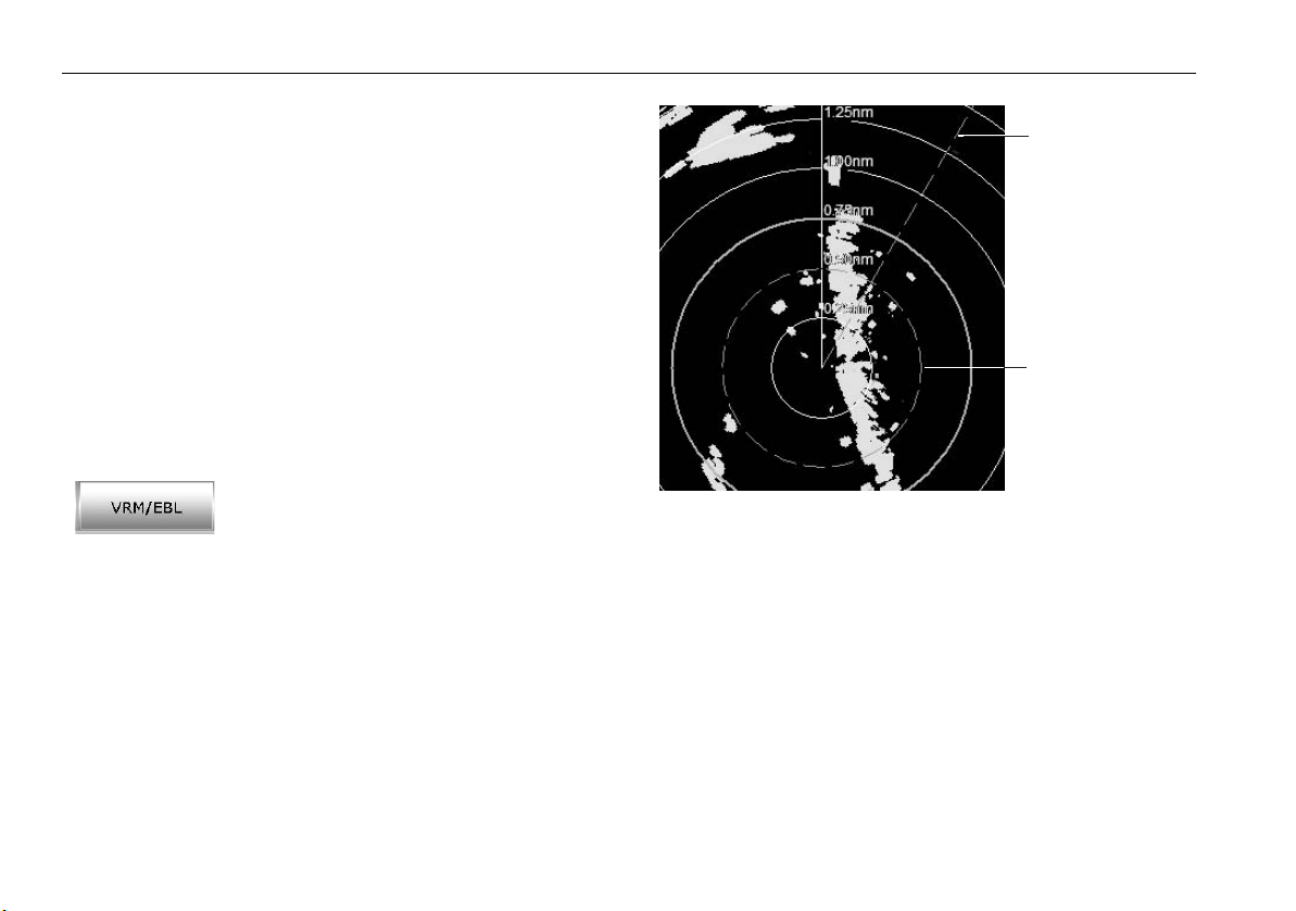
76 RayTech RNS V6.1 - Users Guide
VRMs/EBLs.
A variable range marker (VRM) and its associated electronic bearing line
(EBL) is used to determine the range and bearing (respectively) of objects
detected by the radar.
A standard VRM is displayed as a circle with its center on your boat’s position, and its EBL is displayed as a line from the origin, to the edge of the
radar screen. Both are shown as dotted lines. If you range in or out, or
offset the center of the display, the original setting of the VRM/EBL remains
unchanged. RayTech allows two VRMs/EBLs to be displayed at the same
time.
When a VRM/EBL pair is active, their bearing and range can be displayed in
an associated databox. This is displayed by clicking the
VRM/EBL Box
key to ON.
Using VRM/EBLs
To measure the range and/or bearing of a target
or point from your boat’s position, you need to
display a VRM/EBL and edit (move) it on- screen
D6990_1
so that it intersects the desired target or point.
The first VRM/EBL will be placed at a location 1/3 of the current range and
0
relative to your boat’s head. If this setting is adjusted, the display will
030
retain the adjustments and use them when the VRM/EBL is next turned on.
soft
EBL
VRM
D8776_1
To use a VRM/EBL to tell you how far away a target is and in
what direction it is traveling:
1. Click the
VRM/EBL
soft key. The soft key options for VRM/EBL 1 will
be displayed.
2. Click the
VRM/EBL 1
soft key to ON. The VRM/EBL will be shown on
the radar picture with your boat at its center.
3. Click the
Adjust VRM 1
soft key. The on-screen VRM will change from
a dotted to a solid line.
4. Use the cursor to adjust the VRM to its required size.
5. Click to return the VRM to a dotted line and retain the adjustment.
6. Click the
Adjust EBL 1
soft key. The on-screen EBL will change from a
dotted to a solid line.
7. Use the cursor to place the EBL over the required target.
Page 87
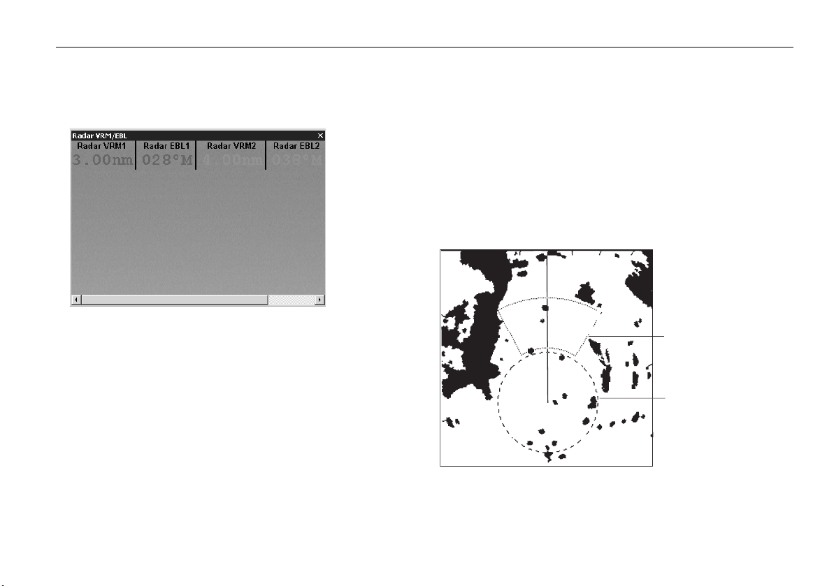
Chapter 10: Working with radar (Analog) 77
8. Click to return the EBL to a dotted line and retain the adjustment.
Note:
When using a VRM/EBL, you may want to turn off the range rings to
make the VRM/EBL easier to see.
D6992_1
The distance and bearing of the target is now shown in the VRM/EBL
databox. You will be able to tell in which direction the target is traveling by
watching how it moves in relation to the EBL. If it continues to travel
directly along the EBL, it indicates that it is on a possible collision course
with your boat - take the appropriate action.
To place the second VRM/EBL pair:
MORE
1. Click the
soft key on the VRM/EBL 1 soft key bar. The softkeys
for VRM/EBL 2 will be displayed.
2. Repeat steps 2 through 8 above. The VRM/EBL will be placed at a location 2/3 of current range and a bearing of 330
o
.
Guard zones
Guard zones enable you to set up one or two sector or 360o zones around
your boat. Any target entering this zoned area will cause a guard alarm to
sound.
Guard zones are fixed with respect to the ship’s heading marker (SHM,
moving as the SHM moves. They also move if you offset the center, or if
you change the range scale, so that the area you have marked is maintained. However, a guard zone only operates when the whole zone is
displayed on the screen, or could be displayed by off-setting the center. In
addition, a guard zone is inactive for 10 seconds after it is placed or resized, to avoid inappropriate alarms during positioning.
Guard zone 1, sector zone
(short-dashed line)
Guard zone 2, circular zone
(long-dashed line)
D8777_1
Page 88

78 RayTech RNS V6.1 - Users Guide
Placing a guard zone
Placing and positioning guard zones on RayTech is quick and easy.
1. Click the
2. Click
3. Click
The default zone is a sector, 30o either side of the SHM, between 1/3
and 2/3 of the current range.
4. Click Set Up Zone 1. The set up soft keys are displayed.
You now have the option of setting a sector or circular guard zone
using the following soft keys:
• Zone shape - enables you to choose sector or circle.
• Set inner - enables you to set the distance of the inner edge of the
• Set outer - enables you to set the distance of the outer edge of the
• Set width - enables you to set the width of a sector zone each side
• Set bearing - enables you to set the bearing of the zone from your
Note:
TARGET TRACKING
MONITOR IN ZONES
Guard Zone 1
zone from your boat.
zone from your boat.
of the SHM.
boat.
to ON. The default zone is displayed.
soft key.
.
The same procedures are used for setting up Guard Zone 2. The
default zone is the same as Guard Zone 1.
10.10 MARPA
Safety Notices
CAUTION: MARPA can improve collision avoidance when used
wisely. It is the user’s responsibility to exercise common
prudence and navigational judgement.
There are conditions where acquiring a target may become difficult. These
same conditions may be a factor in successfully tracking a target. Some of
these conditions are:
• The target echo is weak. The target is very close to land, buoys or other
large targets.
• The target or your own boat is making rapid maneuvers.
• Choppy sea state conditions exist and the target is buried in excessive
sea clutter or in deep swells.
• Choppy sea state conditions exist yielding poor stability; own boat’s
heading data is very unstable.
• Inadequate heading data.
Symptoms of such conditions are that acquisition is difficult, and the
MARPA vectors are unstable; the symbol wanders away from the target,
locks on to another target or changes to a lost target symbol.
If any of these conditions are present, acquisition and tracking may need to
be re-initiated or, in some cases be impossible to maintain. Improving the
quality of the heading data will reduce the effect of the other conditions.
What is MARPA?
You can use the Mini Automatic Radar Plotting Aid (MARPA) functions for
target tracking and risk analysis. MARPA improves collision avoidance by
obtaining detailed information for up to 10 automatically tracked targets
and provides continuous, accurate and rapid situation evaluation.
Page 89
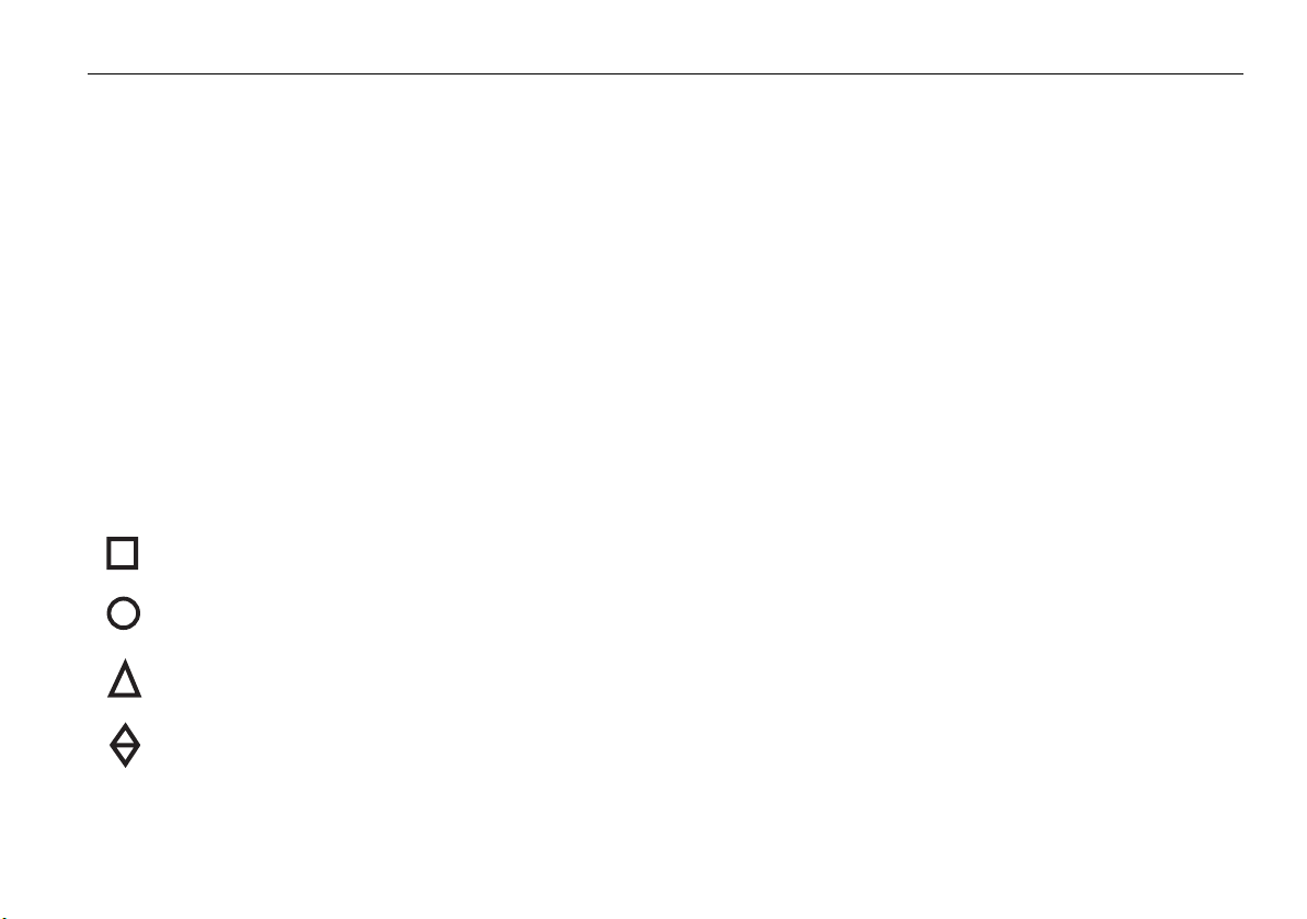
Chapter 10: Working with radar (Analog) 79
MARPA automatically tracks acquired targets, calculates target bearing
and range, true speed and course, Closest Point of Approach (CPA) and
Time to Closest Point of Approach (TCPA).
Each tracked target can be displayed with a vector depicting approximate
target speed (vector length) and course (vector direction). The target data
can be displayed on-screen in the MARPA Target databox, each target is
continually assessed, and you are warned if one becomes dangerous or is
lost.
Effective MARPA operation is dependent on the accuracy of your own ships
heading data, plus Speed over Ground (SOG) and Course Over Ground
(COG). The better the quality of the heading data, the better MARPA will
perform. MARPA will function without SOG and COG data, but only relative vector, CPA and TCPA are shown; target course and speed cannot be
calculated.
Risk assessment
Each target is displayed as a symbol to indicate its status:
Target is being acquired
Target is safe
Target is dangerous
Target is lost
Each target is monitored to determine if it will be within a certain distance
from your own boat within a certain time. If so, the target is designated as
dangerous, and you are notified with an audible alarm and a flashing onscreen ‘MARPA target (ID No.) Dangerous’ warning. Press any key to
cancel the alarm and remove the warning; however, the target is
dangerous symbol remains displayed. Both the distance (Own Vessel Safe
Zone) and the time (Time to Safe Zone) are selectable.
If a target is lost, it is either because the MARPA software has lost contact
with it, or it has moved out of range. If this occurs, you are notified with an
audible alarm and an on-screen ‘MARPA target (ID No.) lost’ warning.
Press any key to silence the alarm and remove the message and lost target
symbol from the screen.
MARPA range
MARPA target acquisition is only available at radar range scales of up to 12
nm, although tracking continues at all ranges.
If you change to a smaller range scale, targets may be beyond the range of
your scanner and will be lost. In such cases, an on-screen warning will indicate that the target is off-screen.
Target and vector history
You can display MARPA targets with a vector line showing where they will
be at a certain time in the future (assuming their present course and speed
remains unchanged). You can select a relative or true vector, and the
vector length.
Relative vector
A relative vector indicates the target’s motion relative to your own boat’s
motion. The target’s relative course and sped are calculated to produce a
Page 90

80 RayTech RNS V6.1 - Users Guide
vector that is displayed on the target only. Relative vector mode is used for
collision avoidance and threat assessment.
True vector
A true vector indicates the targets motion over ground. In this mode, true
vectors for the target and your own boat are displayed. MARPA measures
the direction in which the target and your own boat are moving over the
ground. The result is the boat’s true course and speed. Consider this
motion as if you were in a helicopter looking down watching the targets
move across the water. This mode is used as an aid to navigation.
Target history
You can also view a target’s history, which appears as a trail of dots left by
the target as it travels. You can change the display interval of these dots.
To set up target vectors and history:
1. Click
2. Click
3. Click the action boxes to set mode and distance as required.
4. Use the BACK button to return to the top level softkeys.
Target Tracking
MARPA Options
.
. The MARPA options dialog box is displayed.
MARPA targets
Acquiring MARPA targets
You can acquire up to ten targets, which are then automatically tracked by
the MARPA system. The are three ways in which a MARPA target can be
acquired.
To acquire a MARPA target:
Method 1
1. Click
2. Click
Target Tracking
Acquire Target
.
.
3. Move the cursor over the target you want to acquire and click.
The target acquired symbol will appear at the cursor’s position, and the
radar will search for a target in the location. If a target is present for several
scans, the radar locks on to it and the safe target symbol appears. The target
ID number appears at the safe target symbol. The own vessel safe zone is
also displayed.
4. Repeat Steps 1 through 3 for each target you want to acquire.
Method 2
1. Move the cursor over the target you want to acquire.
2. Right click to display the right-click menu.
3. Highlight and click
4. Highlight and click
5. The target acquired symbol will appear at the cursor’s position, and the
radar will search for a target in the location. If a target is present for
several scans, the radar locks on to it and the safe target symbol
appears. The target ID number appears at the safe target symbol. The
own vessel safe zone is also displayed.
6. Repeat Steps 1 through 4 for each target you want to acquire.
Method 3
Double-click a target on the radar screen.
MARPA
. The target options are displayed.
Acquire
.
Cancelling a MARPA target
There are two ways in which a MARPA target can be cancelled.
To cancel a MARPA target:
Method 1
1. Click
2. Move the cursor over the target you want to cancel and click.
3. The target symbol and ID will disappear from the screen and the target
Cancel Target
is cancelled.
.
Page 91

Chapter 10: Working with radar (Analog) 81
4. Repeat Steps 1 and 2 for each target you want to cancel.
Method 2
1. Move the cursor over the target you want to cancel.
2. Right click to display the right-click menu.
3. Highlight and click
4. Highlight and click
MARPA
. The target options are displayed.
Cancel One
. The target is cancelled.
Viewing MARPA target data
The MARPA database list shows information about your selected targets.
This information includes:
•Target ID.
• Bearing.
•Range.
•Course.
•Speed.
To view the MARPA database list:
1. Click the
2. Click the
displayed.
3. Click
Target Tracking
MARPA List
OK
to remove the list from the screen without editing.
soft key.
soft key. The MARPA database list is now
To edit the MARPA database list:
1. Click
Delete All
. This will delete all of the targets in the list; or,
2. Highlight the targets you want to delete.
3. Click
4. Click
Delete Selected
OK
to remove the dialog box from the screen.
. This will delete only the selected targets.
D6994_1
Page 92

82 RayTech RNS V6.1 - Users Guide
Drop down menus
Toolbars
Status bar
Application
display area
selection tabs
PC taskbar
RayTech Radar screen
Page
Power
key
Title bar
Pathfinder
panel
D6942_1
Function bar
Page 93

Chapter 11: Using the Radar (Digital) 83
Chapter 11: Using the Radar (Digital)
Digital scanners offer:
• Improved target definition.
• Full-color image.
• SuperHD option. Super HD effectively increases the transmitter
power by a factor of at least two, and reduces the beamwidth by a
similar amount. (
options to function
Note:
The radar needs to be receiving heading and position data for full
You require a Super HD radar for the Super HD
).
functionality.
11.1 Radar setup
The Radar Setup Menu lets you customize the way the radar operates.
Changes you make in this menu are kept when you remove power from the
system.
Select scanner
Selects which scanner is displayed in active radar windows.
Scanner setup
The scanner setup option lets you customize various aspects of the
scanner’s behavior, such as the ‘Edit Name’ softkey, which allows you to
name individual scanners.
Short range:
Short range gives a maximum range of 3 nautical miles.
Long range
Long range provides more standard ranges. It is not possible for the long
range to be set to a range less than the short range i.e. if Short range =
3Nm then Long range cannot be less than 3Nm.
Note:
There is no short range operation for Super High Definition (SHD)
radars.
Tune adjust
The tune adjust function is used to fine-tune the scanner’s receiver for
maximum target returns on the display, though we recommend that you
use the automatic settings.
Auto mode: (recommended)
In AUTO mode, the radar tunes itself automatically on all range scales.
This is the default mode and it is recommended that you leave the tune
function in auto mode to ensure that the radar receiver is always tuned to
receive the maximum signal.
Manual mode
If you do set the tune function to MANUAL, you will need to adjust it about
10 minutes after you have turned on the radar, as the required setting will
change after the magnetron has warmed up.
Adjust the control to obtain the maximum signal strength (indicated by the
eight-step horizontal bar). If you cannot tune the radar successfully, refer to
the Installation Guide or return the radar to Auto made.
Page 94

84 RayTech RNS V6.1 - Users Guide
Sea clutter curve
Radar echoes from waves around your boat can clutter the center of the
radar picture, making it difficult to detect real targets. Several factors can
effect the level of clutter you see, such as the mounting height of the radar,
weather and sea conditions. The sea clutter curve settings adjust the
system’s sensitivity to sea clutter. The steepest setting is 1 and the shallowest is 8. The default setting is 1.
Parking offset (Open Array’s)
The default parking offset is 0 degrees: the scanner aligns with the
pedestal, facing forwards.
With parking offset selected you can adjust the parking offset from 0 to
358 degrees in steps of two degrees.
This setting change is only available when the digital radar is set to Off or
Standby. The changes you make are applied the next transmit cycle.
To open the radar setup menu
1. Make a radar application window active.
2. Click the Tools button.
3. Click Radar Setup.
Antenna size
Antenna size selection is available under the radar setup menu. This should
be set by the user.
1. Select ‘Tools’.
2. Select ‘Radar Setup’ from the drop down menu
3. Select Antenna Size, select your required antenna size from the list.
4. Click OK.
Note:
Until you are familiar with interpreting the radar display, take every
opportunity to compare the radar display with your physical
surroundings. Note the location of boats, buoys and coastal structures and their corresponding echoes on the radar display. Practice
harbor and coastal navigation during daylight hours and in clear
weather conditions.
11.2 Powering on/off the various scanner operating modes
To control the power to the radar:
1. Select the Power button.
D10750_1
Page 95

Chapter 11: Using the Radar (Digital) 85
2. Toggle the Scanner On/Off key or,
3. Toggle the Radar Transmit key to On/Off.
Note:
When an open array antenna is fitted, the system stops the
antenna in the forward facing position when Standby mode is
selected.
11.3 Radar range and image quality
Radar operates by transmitting radio pulses, then detecting the reflections
as the pulses bounce back from objects within radar range. The reflections
are processed and displayed on-screen as ‘echoes’.
Range
Radar range is limited by the height of your scanner and the height of the
target, as illustrated below:
R
a
1
h
Radar
R
max
h
H
R
= radar horizon of antenna (
max
The table below gives the approximate range for various antenna and
target heights.
Antenna height
(m)
337.7
31010.9
538.8
51012
max
Earth
R
= 2.23 ( h + H )
max
maximum radar range
radar antenna height
target height
a
) + radar horizon of target (a2)
1
Object height
(m)
a
2
in nautical miles
in metres
in metres
Range
(nm)
H
Cliff
D1643-3
Page 96
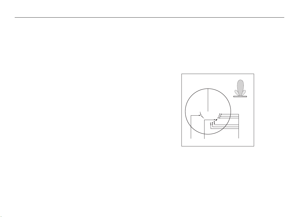
86 RayTech RNS V6.1 - Users Guide
Image quality
Not all radar echoes are produced by valid targets. Spurious echoes may be
caused by:
• Side lobes
• Indirect echoes
• Multiple echoes
• Blind sectors
• Sea, rain or snow clutter
• Interference
Through observation, practice, and experience, you can generally detect
these conditions very quickly and use the radar controls to minimize them.
Side lobes
Side lobe patterns are produced by small amounts of energy from the transmitted pulses that are radiated outside the narrow main beam.
The effects of side lobes are most noticeable with targets at short range
(normally below 3 nm) and with large objects. Side lobe echoes form either
arcs on the radar screen similar to range rings, or a series of echoes
forming a broken arc (see over)...
.
Main lobe
True echo Side echoes
Arc
Side
lobe
Antenna
Side
lobe
D1638-4
Page 97
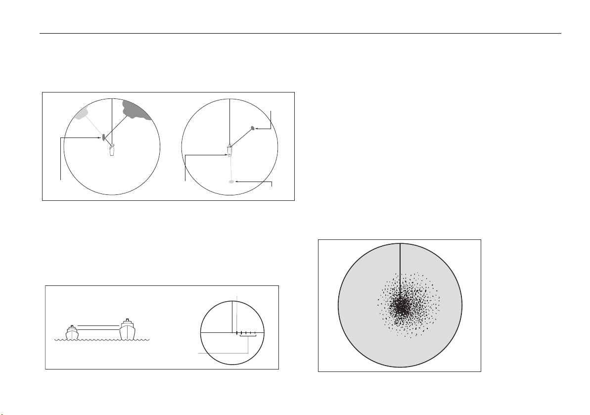
Chapter 11: Using the Radar (Digital) 87
Indirect echoes
There are several types of indirect echoes, or ‘ghost’ images. These sometimes have the appearance of true echoes, but in general they are
intermittent and poorly defined.
False echo
Passing
ship
True echo
Mast
or funnel
True echo
False echo
Multiple echoes
Multiple echoes are uncommon but can occur if there is a large object with
a wide vertical surface at a comparatively short range. The transmitted
signal bounces between the object and your own vessel, producing
multiple echoes. The false echoes are displayed beyond the range of the
true target echo, but on the same bearing.
True echo
Blind sectors
Obstructions such as funnels and masts near the radar antenna can
obstruct the radar beam and cause radar shadows or ‘blind sectors’.
If the obstruction is relatively narrow, there will be a reduction of the beam
intensity, though not necessarily a complete cut-off. However, with wider
obstructions there can be a total loss of signal in the shadow area. There
might also be multiple echoes which extend behind the obstruction.
Blind sector effects can normally be minimized by careful selection of the
scanner site prior to installation.
Sea clutter
Radar returns from waves around the vessel can clutter the center of the
radar picture, making it difficult to detect real targets. Such ‘sea clutter’
usually appears as multiple echoes on the display at short range, and the
D1641-4
echoes are not repetitive or consistent in position.
In high winds or extreme conditions, sea clutter can produce an almost
solid disc on a radar display.
Multiple echoes
D1642-3
D3968-4
Page 98
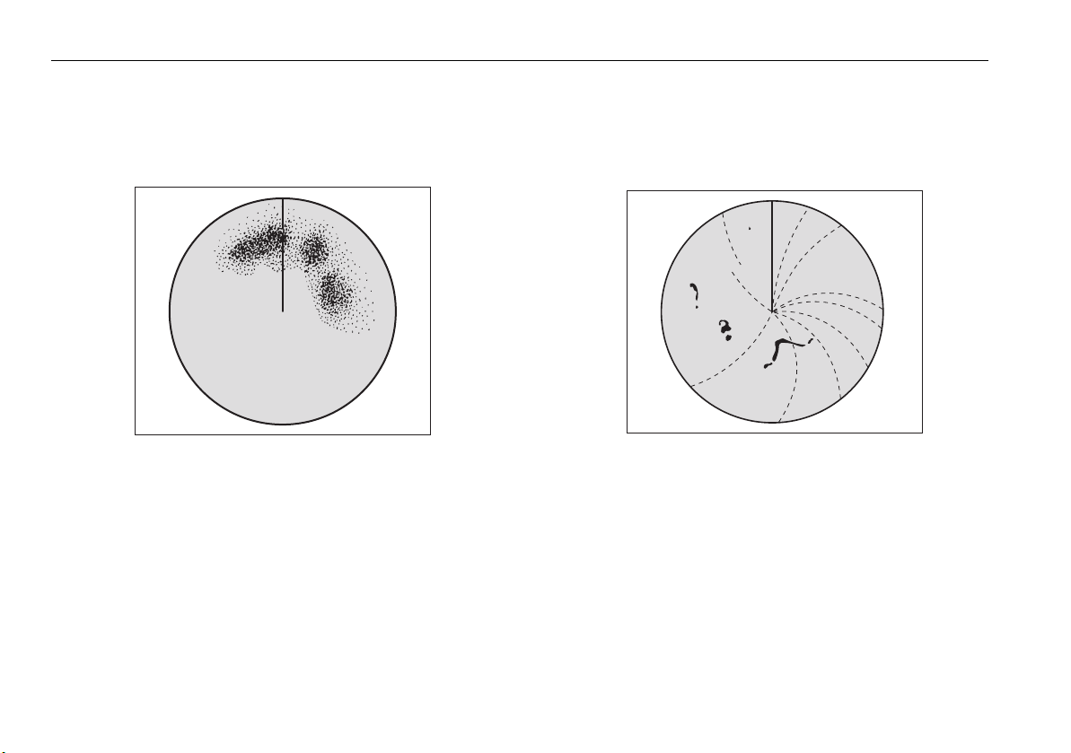
88 RayTech RNS V6.1 - Users Guide
Rain or snow clutter
Radar detects rain and snow. Returns from storm areas and rain squalls
consist of countless small echoes which continually change in size, intensity and position. These returns sometimes appear as large hazy areas,
depending on the intensity of the rainfall or snow in the storm cell.
D3967-4
Mutual radar interference
This can occur when two or more radar-equipped vessels are operating
within range of each other. The interference usually appears as a spiral of
small dots from the display center, and is most marked at long ranges
D6601-2
Page 99
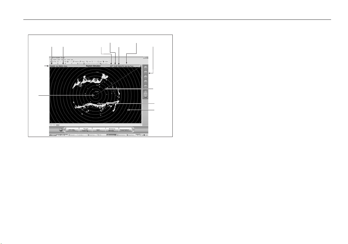
Chapter 11: Using the Radar (Digital) 89
11.4 Radar window overview
Orientation
Orientation
Mode
Data bar
Ships
position
Radar
range
Range
ring
seperation
Your position
By default your boat is shown at the center of the radar display and your
dead-ahead bearing is indicated by a vertical line known as the Ship’s
Heading Marker (SHM).
Operation modes
The radar gives excellent results in one of the four pre configured operation
modes under the Gain softkey. Select the mode that best suits your
circumstances attempting to make manual adjustments to the settings
could degrade your image. (However, this facility is available.) See page 93
for more information.
Motion
mode
Auto
Settings
Pathfinder
panel
D10778_1
Ships
heading
marker
Land mass
Range ring
Other vessels or objects
On-screen targets may be large, small, bright or faint, depending on the
size of the object, its orientation and surface type.
Remember that the strength of an object’s echo may not be proportional to
the physical size of the object. For example, a nearby object might produce
an echo of the same strength as a more distant, but larger object.
With experience, the approximate size of different objects can be determined by the relative size and brightness of the echoes.
Factors affecting echo strength
• The physical size of the reflecting object.
• The material from which the object is made. Metallic surfaces
reflect signals better than non-metallic.
• Vertical surfaces, like cliffs, reflect the radar signal better than
sloping surfaces, like sandbanks.
• High coastlines and mountainous coastal regions can be observed
at longer radar ranges. Therefore, the first sight of land may be a
mountain several miles inland from the coastline. Although the
coastline may be much nearer, it may not appear on the radar until
the vessel is closer to shore.
• Some targets, such as buoys and small boats, can be difficult to
discern, because they do not present a consistent reflecting surface
as they bob about in the waves. Consequently, these echoes tend
to behave erratically on the radar screen.
• Buoys and small boats often resemble each other, but boats can
often be distinguished by their motion.
• Trees and shrubbery’s do not reflect radar. Thus, they can disguise
the shape of nearby land.
Page 100

90 RayTech RNS V6.1 - Users Guide
11.5 Using waypoints with the radar
You can use waypoints in the radar application for navigation (just like in
the chart application), using the WPTS/MOB button.
You can also edit waypoints from within the radar application.
For full details on using waypoints, see
Chapter 7
.
11.6 Radar display options
The Presentation softkey on the radar toolbar gives you control over:
• Waypoint behavior
• Radar mode and orientation
• Range rings
• VRM/EBL behavior
Orientation
Radar orientation refers to the relationship between the radar display and
your direction of travel. There are three orientation modes:
•Head up
• North up
• Course up
These orientation modes are used in conjunction with motion modes (see
page 92) to control how your vessel’s progress is shown on screen.
Heading-Up (H-UP)
This is the default mode for the radar application.
e.g:
N
Ship's Heading Market (SHM)
(indicating the boat's current
heading) is upwards
As your boat's heading changes:
SHM fixed upwards
Radar picture rotates accordingly
N
D8398_1
 Loading...