

Page 1

Constant Running
Hydraulic Pump
Installation Guide
Drives covered:
M81125 Type CR1 (3 L) Constant Running Pump 12 V
M81127 Type CR1 (3 L) Constant Running Pump 24 V
M81126 Type CR2 (4.5 L) Constant Ru nning Pump 12 V
M81128 Type CR2 (4.5 L) Constant Ru nning Pump 24 V
Document number: 81179-3
March 2001
Page 2

2 Constant Running Hydraulic Pump - Installation Guide
Important information
Safety notices
WARNING: Product installation
This equipment must be installed and operated in accordance
with the instructions contained in this handbook. Failure to do so
could result in poor pr oduct performance, personal injury and/
or damage to your boat.
Because correct performance of the boat’s steering is critical for
safety , we STRONGLY RECOMME ND that an Authori zed
Raymarine Service Representative fits this product.
WARNING: Navigation aid
Although we have designed this pr oduct to be accurate and
reliable, many factors can affect its performance. As a result, it
should only be used as an aid to n avigation and should never
replace commons ense and navigational judgement. A lways
maintain a permanent watch so you can respond t o situations as
they develop.
EMC conformance
All Raymarine equipment and accessories are designed to the best
industry standards for use in the recreational marine environment.
The design and manufacture of Raymarine equipment and
accessories conform to the appropriate Electromagnetic
Compatibility (EMC) standards, but correct installation is required to
ensure that performance is not compromised.
Handbook information
T o the best of our knowledge, the information in this han dbook was
correct when it went to press. However, Raymarine cannot accept
liability for any inaccuracies or omissions it may contain. In addition,
our policy of continuous product improvement may change
specifications without notice. As a result, Raymarine cannot accept
liability for any differences between the product and the hand book.
© Raymarine Ltd 2001.
Page 3
Constant Running Hydraulic Pump - Installation Guide 3
Introduction
Product description
W elcome to the installation guide for the Raymarine constant running
(CR) hydraulic pump. This product is intended to operate the boat ’s
steering mechanism as part of a Raymarine autopilot system.
The pump provides an ideal drive system for large boats and heavy
duty steering applications. It is primarily designed for use on boats
with an existing hydraulic steering system. Alternatively , you can use
this pump on a boat with mechanical steering in conjunction with a
secondary steering ram and bypass valve.
The pump contains a built-in reservoir that holds hydraulic fl uid and
an integral solenoid valve that controls the flow of hydraulic fluid t o
the steering ram. The autopilot system steers the boat by using the
solenoid control valves to control the flow of h ydraulic fluid to the
steering ram.
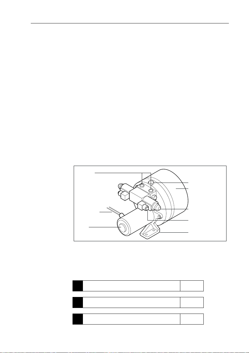
Ram ports
Reservoir port
Reservoir
Figure 1: Main parts of the CR pump
Contents
This guide contains:
Motor cables
Motor
Product specifications page 4
1
Installation instructions page 5
2
Maintenance information page 17
3
Solenoid
control valve x2
Power connector x2
(for solenoid control valve)
Mounting foot
D5176-1
Page 4
4 Constant Running Hydraulic Pump - Installation Guide
Specifications
Pump specifications
Table 1: Pump specifications
Performance
(at nominal voltage)
Ram capacity 350-500 cc
Ram single or double ended
Maximum stall
pressure (at 12 V)
Peak flo w rat e
(no load)
Other information (applies to Types CR1 and CR2)
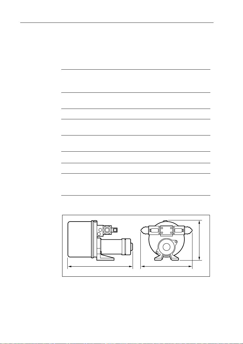
Pump dimensions
Typ e CR1
M81125 (12 V)
M81127 (24 V)
3
(21-30 in
)
50 bar
(750 psi)
3000 cc/min
3
/min)
(180 in
Type CR 2
M81126 (12 V)
M81128 (24 V)
500-1200 cc
(30-73 in3)
50 bar
(750 psi)
4500 cc/min
(270 in3/min)
protected for use in engine compartments
CE approvals - conforms to:
89/336/EC (EMC), EN60945:1997
94/25/EC (RCD), EN28846:1993
356 mm (14 in)
Figure 2: Pump dimensions
262 mm (10.3 in)
224 mm (8.8 in)
D5178-1
Page 5

Constant Running Hydraulic Pump - Installation Guide 5
Installation instructions
Parts required
T o install this drive you will need:
• Parts supplied:
• CR hydraulic pump
• if required: BSP to NP T adaptors (x3)
• Additional parts:
• suitable hydraulic pipes, hydraulic fluid, T -pieces, pipe
fittings and thread-sealing compound (see page8)
• suitable securing bolts, lock washers/lock nuts (see page 7)
• suitable cable and electrical connectors for the drive motor
and solenoid control valves (see page 13)
• CR interface (to connect to Ty pe 100/300 course computer)
• bypass valve (if connecting to a secondary steering ram)
Note: Obt ain these additional parts before you sta rt installation.
Installation steps
WARNING: Electrical safety
Make sure y ou have switched off the power su pply befor e you
start installing this product.
Follow these steps to install your CR pump:
Consult the EMC installation guidelines. page 6
1
Mount the pump. page 7
2
Connect to the hydraulic steering system. page 8
3
Connect to the course computer. page 13
4
Complete the post-installation checks. page 16
5
Ï
Ï
Ï
Ï
Page 6

6 Constant Running Hydraulic Pump - Installation Guide
1. EMC installation guidelines
All Raymarine equipment and accessories are designed to the best
industry standards for use in the recreational marine environment.
Their design and manufacture conforms to the appropriate
Electromagnetic Compatibility (EMC) standards, but correct
installation is required to ensure that performance is not
compromised. Although every effort has been ta ken to ensure that
they will perform under all conditions, it is importa nt to understand
what factors could affect the operation of the product.
The guidelines given here describe the conditions for opti mum EMC
performance, but it is recognized that it may not be possible to meet
all of these conditions in all situations. T o ensure the best possible
conditions for EMC performance within the constraints imposed by
any location, always ensure the maximum separation possible
between different items of electrical equipment.
For optimum EMC perform ance, it is recommended that wherever
possible:
• Raymarine equipment and cables connected to it are:
• At least 3 ft (1 m) from any equipment transmitting or cable s
carrying radio signals e.g. VHF radios, cables and antennas.
In the case of SSB radios, the distance should be increased to
7ft (2m).
• More than 7 ft (2 m) from the path of a radar beam. A radar
beam can normally be assumed to spread 20 degrees above
and below the radiating element.
• The equipment is supplied from a separate battery from that used
for engine start. Voltage drops below 10 V , and starter motor
transients, can cause the equipment to reset. This will not damage
the equipment, but may cause the loss of some information and
may change the operating mode.
• Raymarine specified cables are used. Cutting and rejoining these
cables can compromise EMC performance and must be avoided
unless doing so is detailed in the installation manu al.
• If a suppression ferrite is attached to a cable, this ferrite should no t
be removed. If the ferrite needs to be removed d uring installation
it must be reassembled in the same position.
Page 7

Constant Running Hydraulic Pump - Installation Guide 7
Suppression ferrites
This figure shows typical cable suppression ferrites us ed with
Raymarine equipment. Always use the ferrites suppl ied by
Raymarine.
D3548-2
Connections to other equipment
If your Raymarine equipment is to be connected to other equipment
using a cable not supplied by Raymarine, a suppression ferrite MUST
always be attached to the cable near to the Raymarine unit.
2. Pump mounting
CAUTION:
During installation, take care not to knock the CR pump’s
mounting feet on any solid structures as the impact may damage
the aluminium castings.
Mount the CR pump:
• on a substantial member to avoid vibration that could damage the
hydraulic pipes
• on a suitable horizontal surface clear of spray and possible water
immersion
• level or above the hydraulic steering ram to prevent air collecting
in the ram
• as close to the steering ram as possible
• using suitable bolts with lock nuts/lock washers
Note: As the pump can transmit noise to the boat’s st ructure, we
recommend placing rubber mounts between the pump and the boat’s
structure to reduce noise transfer.
CAUTION:
Locate the pump in a ventilated and soundpr oof enclosure.
Page 8

8 Constant Running Hydraulic Pump - Installation Guide
3. Hydraulic connections
CAUTION:
Before you connect the autopilot pump to your hydraulic system
we strong ly recomm end that you con sult the stee ring gear
manufacturer.
General guidelines
CAUTION:
Absolute cleanliness is essential when working with hydraulic
systems. Even the smallest particle of dirt could prevent the
steering system check valves fr om working properly .
• All pipes used to fit the pump should match, or exceed, the
specification of the existing steering system pipes. Contact the
steering system manufacturer if you need more information.
• Use flexible pipe to connect the pump to the boat’s steering
system - this avoids strain on the pipes .
• Try to keep hydraulic fluid loss to a minimum when installing the
pump. This will reduce the time and effort required to bleed the
system of trapped air after installation:
• non-pressurized systems: temporarily fit a non-ventin g plug
to the helm reservoir vent to minimize fluid loss
• pressurized systems:
WARNING:
Before disconnecting any pipes on pressurized systems, you
MUST release the pressure at the reservoir by following the
manufacturer’s instructions.
• The ram ports on the CR pump are tapped to
reservoir port is tapped to
3
/
in BSP. Three N P T adapto rs are
8
included for conversion to NPT where required.
• Follow the manufacturer’s instructions if you f it any T -pieces.
• Make sure all hydraulic pipes slope upwards towards the
reservoir.
• A set of bleed valves near the steering ram, fitted at the highest
point, will allow any air to escape upwards.
1
/
in BSP and the
4
Page 9

Constant Running Hydraulic Pump - Installation Guide 9
CAUTION:
Do not use P TFE tape on hydraulic pipe c onnections. If necessary
use a pipe-sealing compound t o ensure a leakpr oof joint.
CAUTION:
Before running the pump for the first time, make sure the system
contains suffi cient hydrauli c fluid. You will damage th e pump if
you let it run when ‘dry’.
Check valves
For single-steering position boats:
• Consult the steering gear manufacturer to determine whether the
helm pump is fitted with reversing check valves:
• without check valves, the autopilot pump will drive the helm
pump (sometimes referred to as ‘motoring the wheel’) instead
of moving the steering ram
• If the boat has a single helm pump system without check valves,
you must incorporate a double pilot check valve (part number:
M81166) as shown in Fi gure 3.
• A double pilot check valve may also be necessary on long pipe
runs - otherwise pipe expansion may cause poor autopilot
performance. Install the check valve as shown in Figure 3.
Note: If the boat has two steering positions, it will already have check
valves installed so the two wheels can operate independently.
Hydraulic steering systems
There are three basic types of hydraulic steering systems:
• two line system
• three line system
• two line pressurized system
On the following pages we describe each type of system and typical
connection points for the autopilot pump. For all of these systems you
will ne ed to connect a third hydraulic pipe as shown between the
autopilot pump and t he helm pump or d edicated system reservoir .
Page 10

10 Constant Running Hydraulic Pump - Installation Guide
Two line systems
Figure 3 shows a typical two line steering system. Hydraulic fluid
flows into the ram in either direction, depending on the direction the
helm pump rotates.
Connect the autopilot pump to the steering system as shown in
Figure 3.
Helm
pump
Check valve (if required)
Reservoir pipe
Ram pipes
Steering ram
CR pump
Figure 3: Autopilot pump location for two line systems
D
5168-1
Page 11

Constant Running Hydraulic Pump - Installation Guide 11
T wo line pressurized systems
T wo line pressurized systems have an external pressurized reservoir.
This reduces the possibility of introducing air i nto the system and
reduces any steering ‘sponginess’ caused by pipe expansion .
Connect the autopilot pump to the steering system as shown in
Figure 4.
Note: Refer to the manufacturer’s instructions for de-pr essurizing
and re-pressurizing the system.
Helm
pump
Reservoir pipe
Ram pipes
Steering ram
CR pump
5167-1
D
Figure 4: Autopilot pump location for two line pressurized systems
Page 12

12 Constant Running Hydraulic Pump - Installation Guide
Three line systems
In a three line system, the hydraulic fluid flows in only one direction:
• out of the helm pump to the ram
• returning from the other side of the ram to the reservoir via a
common return line
The system will include a check valve block to direct all returned
fluid from the ram back to the reservoir .
Connect the autopilot pump to the steering system as shown in
Figure 5.
Helm
pump
Check valve
CR pump
Reservoir
pipe
Ram pipes
Steering ram
Figure 5: Autopilot pump location for three line systems
D
5166-1
Page 13

Constant Running Hydraulic Pump - Installation Guide 13
4. Connecting to the course computer
WARNING: Electrical safety
Make sure the power su pply is swi tched off befo re you make any
electrical connections.
The CR pump has electrical connections for:
• motor supply: two single-core cables
• solenoid control valve supply: two plug-i n connectors (supplied)
Note: When routing cables, refer to the EMC installation guidelines.
Connecting to Type 150/400 course computer
Make the following connections:
1. CR pump motor supply:
• using appropriate cables (see Table 2) connect the CR pump
motor to the boat’s power supply , via an appropriate circuit
breaker and fuse (as specified in Figure 6)
2. Solenoid control val ves – using suitable cable (at least 16 AWG or
2
1.5 mm
• for the first valve: connect one core to the
for runs up to 16 m/52 ft):
and the other core to one of the
MOTOR A terminal
SOLENOID terminals at the
course computer (see Figure 6)
• for the second valve: connect one core to the
terminal and the other core to the other
SOLENOID terminal
MOTOR B
Note:
If installing the pump on a boat with mechanical steering, you
need to connect a bypass valve to the
Table 2: Recommended cable sizes
Pump motor cable length
(distribution panel to pump)
12 V CR pumps
24 V CR pumps
up to 3 m (10 ft)
up to 7 m (23 ft)
up to 16 m (52 ft)
up to 3 m (10 ft)
up to 5 m (16 ft)
up to 10 m (32 ft)
up to 16 m (52 ft)
CLUTCH
Cable gauge
(AWG)
10
8
6
12
10
8
6
terminals (see page 15).
Copper area
2
)
(mm
6
10
16
4
6
10
16
Page 14

14 Constant Running Hydraulic Pump - Installation Guide
Course computer
connections
O
SW
FF
To boat's battery
CR1 (12V) - 50A
CR1 (24V) - 30A
CR2 (12V) - 70A
CR2 (24V) - 40A
Circuit
breaker
ITCH
Fuse
Solenoid 'B' cable
Motor supply
Solenoid 'A' cable
CR pump
+–
A
MOTORPOWER
B
To bypass valve
(if required)
–
SO
–
LEN
O
–
ID
CLU
+
TCH
D5189-2
Figure 6: CR pump connections to a Type 150/400 course computer
Connecting to Type 100/300 course computer
When installing the CR pump with a T ype 100/ 300 course computer
we recommend using a Raymarine constant running (CR) inte rface
(part number: M81129).
Connecting the CR interface
Run cables from the main power supply to:
• the motor on the CR pump
• the CR interface and then onto the course computer power
connections
Install a suitable circuit breaker in the power supply to the co mplete
system (as specified in the core pack installation guide).
Note: It is important to use the correct cable size for the length of
cable run between the pump and the power supply (see Table 2).
The CR interface unit has connections for the solenoid valves (on the
CR pump) and a bypass valve (if fitting to a mechanical steering
system):
• connect the solenoid valves to the CR interface as shown in
Figure 7, using at least 16 A WG (1.5 mm
2
) cable.
Page 15

Constant Running Hydraulic Pump - Installation Guide 15
2
Circuit breaker
Fuse
Course computer
12 V - 25 A
24 V - 10 A
Supply
To bypass
valve (if
required)
CR1 (12 V) – 50 A
CR1 (24 V) – 30 A
CR2 (12 V) – 70 A
CR2 (24 V) – 40 A
1
3
Solenoid 'B' cable
Motor supply
5
1
2
4
Solenoid 'A' cable
+ –
BYPASS
VALVE
+ – + –
BATTERY
SOLENOIDS
3
4
5
A B
Type CR
interface unit
+ –
+
–
+
–
CLUTCH
SUPPLY
Course computer
connections:
CLUTCH
M1 M2
Figure 7: CR pump connections to a Type 100/300 course computer
Mechanical steering
If you are fitting the pump to a boat w ith mechanical steering you will
need to connect it to a secondary steering ram, along with a solenoidoperated bypass valve (part no. M81167 ). The bypass valve allows
you to switch between autopilot course control and manual steering.
T o fit to a mechanical steering system:
1. Use suitable hydraulic pipes to connect the pump to the secondary
steering ram and a suitable reservoir.
2. Install the solenoid-operated bypass valve across these pipes (as
shown in Figure8).
3. Connect the bypass valve to:
• the
CLUTCH terminals on the course computer (T ype 150/400
course computer), or
• the
BYPASS terminals on the CR interface (T ype 100/300
course computer
Note: Fo llow the manufacturer’s instructions for mounting the
hydraulic ram.
POWER
MOTOR
D5164-2
Page 16

16 Constant Running Hydraulic Pump - Installation Guide
Secondary steering ram
Bypass valve
Hydraulic pipes to
CR pump
Manual steering system Connect to:
CLUTCH terminal on 150/400 course computer
BYPASS on CR connector (100/300 course computer)
Figure 8: Connecting the bypass valve
5. Post-installation check
WARNING:
Keep clear of moving steering systems at all times. Protect
moving parts from access during normal use.
Check the following points after installing t he pump:
1. Is the pump installed as close to the steering ram as possible?
2. Is the pump secured to a substantial struct ure on the boat?
3. Have you connected a third hydraulic pipe between t he helm
pump and autopilot pump?
4. Have you fitted check valves where appropriate?
5. Are the hydraulic pipes made of a suitable flexible material (i.e.
rubber or nylon) with a suitable pressure rating?
6. Have you sealed all hydraulic connections and che cked for leakages?
7. Are power cables correctly routed and securely connected to the
course computer?
Y ou have now finished installing the pump. After installing the rest of
the autopilot you must bleed all air from the system (see below).
D5177-1
Note: W hen you have installed the entire autopilot system, you wil l
also need to complete an autopilot steering check. Refer to the control
unit handbook for more details.
Bleeding the system
Bleeding the hydraulic system correctly is one of the most important
steps when installing the autopilot hydraulic pump. If there is any air
Page 17

Constant Running Hydraulic Pump - Installation Guide 17
in the system the steering will feel spongy, particularl y when you turn
the wheel to hardover.
CAUTION:
Any air in the hydraulic system will greatly reduce the
performance of the autopilot and the overall steering system.
In addition to the manufacturer’s instruct ions for bleeding the
steering system, follow these steps to bleed the autopilot pump when
you have installed and set up the rest of the autopi lot system:
1. With the system in
• the autopi lot pump w ill try to d rive the r udder to po rt
• counter this rudder movement by turning the helm to
starboard to keep the rudder stationary
• you will be able to feel any air in the helm pump: any air in this
side of the pump will rise to the helm pump and exhaus t into
the reservoir
• continue until all of the air is out of this side of the pump
2. Clear any air on the other side of the pump:
• press the
• the autopilot will try to drive the rudder to starboard
• counter the rudder movement by turning the helm to port
• continue until all of the air is out of this side of the pump
3. Repeat in both directions until b oth sides of the help pump are
totally free of air.
auto mode, press the -10 button ten times:
+10 button te n times
Note: M onitor the reservoir at all tim es and top up with the
manufacturer’s recommended hydraulic fluid as required.
CAUTION:
After installation and bleeding, leave the system for 24 hours
then check for any air in the system or leaks at the joints and
around the pump.
Maintenance
On a regular basis:
• check all connections and mountings are secure
• check pipes and cables for any signs of wear or damage
• check hydraulic pipes and connections for leaks
Page 18

18 Constant Running Hydraulic Pump - Installation Guide
EMC servicing and safety guidelines
• Raymarine equipment should be serviced only by authorized
Raymarine service technicians. They will ensure that service
procedures/ replacement parts used will not affect performance.
There are no user serviceable parts in any Raymarine product.
• Some products generate high voltages, so never handle the cables
or connectors when power is being supplied to the equipment.
• When powered up, all electrical equipment produces
electromagnetic fields. These can cause adjacent pieces of
electrical equipment to interact with one another, with a
consequent adverse effect on operation. In order to minimize
these effects and enable you to get the best possible performance
from your Raymarine equipment, guidelines are given in the
installation instructions, to enable you to ens ure minimum
interaction between different items of equipment, i.e. ensure
optimum Electromagnetic Compatibility (EMC).
• Always report any EMC-related problem to your nearest Raymarin e
dealer. W e use such information to improve our quality standards.
• In some installations, it may not be possible to preven t the
equipment from being affected by ext ernal influences. In general
this will not damage the equipment but it can lead to spurious
resetting action, or momentarily may result in faulty operation.
Product support
Raymarine products are supported by a worldwide network of
distributors and Authorized Service Representa tives. If you
encounter any difficulties with thi s product, please contact either
your national distributor , service representative, or the Raymarine
T echnical Services Call Center.
Raymarine Ltd
Anchorage Park
Portsmouth, Hampshire
England PO3 5TD
Telephone +44 (0)23 9269 3611
Fax +44 (0)23 9269 4642
www.raymarine.com
Raymarine Technical Services Call Center
UK: +44 (0)23 9271 4713 or
+44 (0)23 9269 3611 ext. 1083
Raymarine Inc
22 Cotton Road, Suite 280
Nashua
NH 03063-4219, USA
Telephone +1 603 881 5200
Fax +1 603 864 4756
www.raymarine.com
USA: +1 603 881 5200 or
1-800-539-5539 ext. 2333
 Loading...