

Page 1

i60 W
ind
i60 CH W ind
Installation and operation
instructions
English
Date: 06-2014
Document number: 81342-2-EN
© 2014 Raymarine UK Limited
TackTrue/AppDisplay VMG
Page 2

Page 3

Trademarkandpatentsnotice
Raymarine,Tacktick,ClearPulse,Truzoom,HSB,SeaTalk,SeaTalk
hs
,SeaTalk
ng
,Micronet,Raytech,
GearUp,MarineShield,Seahawk,Autohelm,Automagic,andVisionalityareregisteredorclaimed
trademarksofRaymarineBelgium.
FLIR,DownVision,SideVision,Dragony,Instalert,InfraredEverywhere,andTheWorld’sSixth
SenseareregisteredorclaimedtrademarksofFLIRSystems,Inc.
Allothertrademarks,tradenames,orcompanynamesreferencedhereinareusedforidenticationonly
andarethepropertyoftheirrespectiveowners.
Thisproductisprotectedbypatents,designpatents,patentspending,ordesignpatentspending.
FairUseStatement
Youmayprintnomorethanthreecopiesofthismanualforyourownuse.Youmaynotmakeanyfurther
copiesordistributeorusethemanualinanyotherwayincludingwithoutlimitationexploitingthemanual
commerciallyorgivingorsellingcopiestothirdparties.
Softwareupdates
Checkthewebsitewww.raymarine.comforthelatestsoftwarereleasesforyourproduct.
Producthandbooks
ThelatestversionsofallEnglishandtranslatedhandbooksareavailabletodownloadinPDFformatfromthewebsite
www.raymarine.com.
Pleasecheckthewebsitetoensureyouhavethelatesthandbooks.
Copyright©2014RaymarineUKLtd.Allrightsreserved.
ENGLISH
Documentnumber:81342-2
Date:06-2014
Page 4

Page 5

Contents
Chapter1Importantinformation........................7
CertiedInstallation...................................................7
Wateringress............................................................7
Disclaimer.................................................................7
EMCinstallationguidelines........................................7
Suppressionferrites...................................................8
Connectionstootherequipment.................................8
Declarationofconformity............................................8
Productdisposal........................................................8
Warrantyregistration..................................................8
IMOandSOLAS........................................................8
Technicalaccuracy....................................................9
Chapter2Handbookinformation.......................11
2.1Documentinformation..........................................12
2.2Partssupplied......................................................13
2.3i60Productoverview............................................13
Chapter3Planningtheinstallation...................15
3.1Installationchecklist.............................................16
3.2Compatibletransducers........................................16
3.3Typicalsystems...................................................17
3.4Systemprotocols.................................................19
3.5T oolsrequired......................................................19
3.6Selectingadisplaylocation...................................20
3.7Productdimensions..............................................21
3.8Windvanetransducer/rotavectalocation
requirements.............................................................21
Chapter4Cablesandconnections....................23
4.1Generalcablingguidance.....................................24
4.2Powerconnection................................................24
4.3SeaT alk
4.4Transducerconnections.......................................26
4.5iTC-5connection..................................................26
4.6SeaT alkconnection..............................................27
4.7NMEA2000connection.........................................28
ng
connections..........................................25
8.3Illumination..........................................................46
Chapter9Alarms.................................................47
9.1Alarms.................................................................48
Chapter10Maintainingyourdisplay.................49
10.1Serviceandmaintenance...................................50
10.2Condensation.....................................................50
10.3Routineequipmentchecks..................................51
10.4Cleaning............................................................51
10.5Cleaningthedisplaycase...................................52
10.6Cleaningthedisplayscreen................................52
Chapter11Troubleshooting...............................53
11.1Troubleshooting..................................................54
11.2Instrumenttroubleshooting..................................55
11.3Poweruptroubleshooting....................................56
11.4Miscellaneoustroubleshooting............................57
Chapter12Technicalsupport............................59
12.1Raymarinecustomersupport..............................60
12.2Checkingthesoftwareversion............................60
Chapter13Technicalspecication....................61
13.1T echnicalspecication........................................62
Chapter14Sparesandaccessories..................63
14.1Spares...............................................................64
14.2SeaT alk
14.3Converters.........................................................65
ng
cablesandaccessories.......................64
AppendixANMEA2000sentences...................67
Chapter5Mounting.............................................29
5.1Mounting.............................................................30
5.2Frontbezel..........................................................31
Chapter6Gettingstarted...................................33
6.1Controls...............................................................34
6.2Power.................................................................34
6.3Datamaster.........................................................35
Chapter7Calibration..........................................37
7.1Usercalibration....................................................38
7.2Intermediatecalibration........................................39
7.3Dealercalibration.................................................39
Chapter8Usingyourdisplay.............................43
8.1Pages.................................................................44
8.2i60Windoperation...............................................44
5
Page 6

6i60
Page 7

Chapter1:Importantinformation
CertiedInstallation
Raymarinerecommendscertiedinstallationbya
Raymarineapprovedinstaller.Acertiedinstallation
qualiesforenhancedproductwarrantybenets.
ContactyourRaymarinedealerforfurtherdetails,
andrefertotheseparatewarrantydocumentpacked
withyourproduct.
Caution:Transducercable
•DoNOTcut,shorten,orsplicethe
transducercable.
•DoNOTremovetheconnector.
Ifthecableiscut,itcannotberepaired.
Cuttingthecablewillalsovoidthe
warranty.
Caution:Serviceandmaintenance
Warning:Productinstallationand
operation
Thisproductmustbeinstalledand
operatedinaccordancewiththe
instructionsprovided.Failuretodoso
couldresultinpersonalinjury,damage
toyourvesseland/orpoorproduct
performance.
Warning:Potentialignitionsource
ThisproductisNOTapprovedforusein
hazardous/ammableatmospheres.Do
NOTinstallinahazardous/ammable
atmosphere(suchasinanengineroom
ornearfueltanks).
Warning:Positivegroundsystems
Donotconnectthisunittoasystemwhich
haspositivegrounding.
Caution:Powersupplyprotection
Wheninstallingthisproductensurethe
powersourceisadequatelyprotected
bymeansofasuitably-ratedfuseor
automaticcircuitbreaker.
Warning:Switchoffpowersupply
Thisproductcontainsnouserserviceable
components.Pleasereferallmaintenance
andrepairtoauthorizedRaymarine
dealers.Unauthorizedrepairmayaffect
yourwarranty .
Wateringress
Wateringressdisclaimer
Althoughthewaterproofratingcapacityofthis
productmeetsthestatedIPXstandard(refertothe
product’sTechnicalSpecication),waterintrusion
andsubsequentequipmentfailuremayoccurifthe
productissubjectedtocommercialhigh-pressure
washing.Raymarinewillnotwarrantproducts
subjectedtohigh-pressurewashing.
Disclaimer
Raymarinedoesnotwarrantthatthisproductis
error-freeorthatitiscompatiblewithproducts
manufacturedbyanypersonorentityotherthan
Raymarine.
Raymarineisnotresponsiblefordamagesorinjuries
causedbyyouruseorinabilitytousetheproduct,
bytheinteractionoftheproductwithproducts
manufacturedbyothers,orbyerrorsininformation
utilizedbytheproductsuppliedbythirdparties.
Ensurethevessel’spowersupplyis
switchedOFFbeforestartingtoinstallthis
product.DoNOTconnectordisconnect
equipmentwiththepowerswitchedon,
unlessinstructedinthisdocument.
Warning:Highvoltage
Thisproductcontainshighvoltage.
Adjustmentsrequirespecializedservice
proceduresandtoolsonlyavailableto
qualiedservicetechnicians.Thereare
nouserserviceablepartsoradjustments.
Theoperatorshouldneverremovethe
coverorattempttoservicetheproduct.
Importantinformation
EMCinstallationguidelines
Raymarineequipmentandaccessoriesconformto
theappropriateElectromagneticCompatibility(EMC)
regulations,tominimizeelectromagneticinterference
betweenequipmentandminimizetheeffectsuch
interferencecouldhaveontheperformanceofyour
system
CorrectinstallationisrequiredtoensurethatEMC
performanceisnotcompromised.
Note:InareasofextremeEMCinterference,
someslightinterferencemaybenoticedonthe
product.Wherethisoccurstheproductandthe
sourceoftheinterferenceshouldbeseparatedby
agreaterdistance.
ForoptimumEMCperformancewerecommend
thatwhereverpossible:
•Raymarineequipmentandcablesconnectedto
itare:
7
Page 8

–Atleast1m(3ft)fromanyequipment
transmittingorcablescarryingradiosignalse.g.
VHFradios,cablesandantennas.Inthecase
ofSSBradios,thedistanceshouldbeincreased
to7ft(2m).
–Morethan2m(7ft)fromthepathofaradar
beam.Aradarbeamcannormallybeassumed
tospread20degreesaboveandbelowthe
radiatingelement.
•Theproductissuppliedfromaseparatebattery
fromthatusedforenginestart.Thisisimportantto
preventerraticbehavioranddatalosswhichcan
occuriftheenginestartdoesnothaveaseparate
battery.
•Raymarinespeciedcablesareused.
•Cablesarenotcutorextended,unlessdoingsois
detailedintheinstallationmanual.
Note:Whereconstraintsontheinstallation
preventanyoftheaboverecommendations,
alwaysensurethemaximumpossibleseparation
betweendifferentitemsofelectricalequipment,to
providethebestconditionsforEMCperformance
throughouttheinstallation
Caution:Cleaning
Whencleaningthisproduct:
•DoNOTwipethedisplayscreenwith
adrycloth,asthiscouldscratchthe
screencoating.
•DoNOTuseabrasive,oracidor
ammoniabasedproducts.
•DoNOTuseajetwash.
Caution:Condensation
Certainatmosphericconditionsmay
causeasmallamountofcondensation
toformontheunit'swindow.Thiswill
notdamagetheunitandwillclearafter
theunithasbeenswitchedonforashort
period.
Declarationofconformity
RaymarineUKLtd.declaresthatthisproductis
compliantwiththeessentialrequirementsofEMC
directive2004/108/EC.
Suppressionferrites
Raymarinecablesmaybettedwithsuppression
ferrites.TheseareimportantforcorrectEMC
performance.Ifaferritehastoberemovedforany
purpose(e.g.installationormaintenance),itmustbe
replacedintheoriginalpositionbeforetheproduct
isused.
Useonlyferritesofthecorrecttype,suppliedby
Raymarineauthorizeddealers.
Whereaninstallationrequiresmultipleferritestobe
addedtoacable,additionalcableclipsshouldbe
usedtopreventstressontheconnectorsduetothe
extraweightofthecable.
Connectionstootherequipment
Requirementforferritesonnon-Raymarinecables
IfyourRaymarineequipmentistobeconnected
tootherequipmentusingacablenotsuppliedby
Raymarine,asuppressionferriteMUSTalwaysbe
attachedtothecableneartheRaymarineunit.
Caution:Suncovers
•T oprotectyourproductagainstthe
damagingeffectsofultraviolet(UV)
light,alwaystthesuncoverswhenthe
productisnotinuse.
TheoriginalDeclarationofConformitycerticate
maybeviewedontherelevantproductpageat
www.raymarine.com.
Productdisposal
Disposeofthisproductinaccordancewiththe
WEEEDirective.
TheWasteElectricalandElectronicEquipment
(WEEE)Directiverequirestherecyclingofwaste
electricalandelectronicequipment.Whilstthe
WEEEDirectivedoesnotapplytosomeRaymarine
products,wesupportitspolicyandaskyoutobe
awareofhowtodisposeofthisproduct.
Warrantyregistration
ToregisteryourRaymarineproductownership,
pleasevisitwww.raymarine.comandregisteronline.
Itisimportantthatyouregisteryourproductto
receivefullwarrantybenets.Y ourunitpackage
includesabarcodelabelindicatingtheserialnumber
oftheunit.Youwillneedthisserialnumberwhen
registeringyourproductonline.Youshouldretain
thelabelforfuturereference.
•Removethesuncoverswhentravelling
athighspeed,whetherinwaterorwhen
thevesselisbeingtowed.
8i60
IMOandSOLAS
Theequipmentdescribedwithinthisdocument
isintendedforuseonleisuremarineboatsand
workboatsNOTcoveredbyInternationalMaritime
Organization(IMO)andSafetyofLifeatSea
(SOLAS)CarriageRegulations.
Page 9

Technicalaccuracy
Tothebestofourknowledge,theinformationinthis
documentwascorrectatthetimeitwasproduced.
However,Raymarinecannotacceptliabilityforany
inaccuraciesoromissionsitmaycontain.Inaddition,
ourpolicyofcontinuousproductimprovementmay
changespecicationswithoutnotice.Asaresult,
Raymarinecannotacceptliabilityforanydifferences
betweentheproductandthisdocument.Please
checktheRaymarinewebsite(www.raymarine.com)
toensureyouhavethemostup-to-dateversion(s)of
thedocumentationforyourproduct.
Importantinformation
9
Page 10

10i60
Page 11

Chapter2:Handbookinformation
Chaptercontents
•2.1Documentinformationonpage12
•2.2Partssuppliedonpage13
•2.3i60Productoverviewonpage13
Handbookinformation
11
Page 12
2.1Documentinformation
TackTrue/AppDisplay VMG
TackTrue/AppDisplay VMG
TackTrue/AppDisplay VMG
Depth Alarm Offse t ResetSpeed Trip Timer Reset
TackTrue/AppDisplay VMG
Documentillustrations
Thisdocumentcontainsimportantinformation
relatedtotheinstallationofyourRaymarineproduct.
Thedocumentincludesinformationtohelpyou:
•planyourinstallationandensureyouhaveallthe
necessaryequipment;
•installandconnectyourproductaspartofawider
systemofconnectedmarineelectronics;
•troubleshootproblemsandobtaintechnical
supportifrequired.
ThisandotherRaymarineproductdocuments
areavailabletodownloadinPDFformatfrom
www.raymarine.com.
Applicableproducts
Thisdocumentisapplicabletothefollowingproducts:
Part
ItemModel
i60WindE70061i60Wind
numberHardware
SeaTalk
ng
instrumentdisplay
Yourproductmaydifferslightlyfromthatshown
intheillustrationsinthisdocument,dependingon
productvariantanddateofmanufacture.
Allimagesareprovidedforillustrationpurposesonly.
Productdocumentation
Thefollowinghandbooksareapplicabletoyour
product:
Handbooks
DescriptionPartnumber
i60Installationandoperation
instructions
Installationandoperationinstructions
forthei60instrumentdisplay
i60Mountingtemplate
Surfacemountingtemplateforthei60
instrumentdisplay
RotavectaInstallationinstructions
Installationinstructionsforthe
Rotavectawindtransducer
81342/88010
87130
87221/88036
i60Close
HauledWind
i60Wind
systempack
i50&i60
Depth,
Speed&
Windsystem
pack
E70062
E70150•i60Wind
E70153•i50Depth
i60CloseHauled
WindSeaTalk
instrumentdisplay
(repeater)
SeaTalk
ng
instrument
display
•Shortarm
windvane
transducer
SeaTalk
ng
instrument
display
•P319ThruhullDepth
transducer
•i50Speed
SeaTalk
ng
instrument
display
Short&longarmwindvane
87220/88035
Installationinstructions
ng
Installationinstructionsfortheshortand
longarmwindvanetransducers
•P120ThruhullSpeed
andTemp
transducer
•i60Wind
SeaTalk
ng
instrument
display
•Shortarm
12
windvane
transducer
i60
Page 13

2.2Partssupplied
D1238 8-1
1 2
5 6
98
43
7
TackTrue/AppDisplay VMG TackTrue/AppDisplay VMG
1 2
D12549-2
2.3i60Productoverview
1i60instrument
2Frontbezel
3
4
5
6
7
8
9
SeaTalktoSeaTalk
cable
SeaTalk
ng
spurcable
Gasket
Suncover
Documentationpack
SeaTalk
ng
blankingplug
4xxingscrews
Thei60rangeofSeaTalk
ng
instrumentdisplays
canbeconnecteddirectlytothecompatiblewind
transducers.Thedatacanbetransmittedonthe
SeaTalk
ng
networktoothercompatibledisplays.
Raymarine'si60instrumentrangeconsistsofthe
followingvariants:
1.i60Wind—Thei60Windinstrumentprovides
a360ºwinddirectionscaleandcanbeusedas
astandaloneunitoraspartofaSeaT alkor
SeaTalk
ng
network.
2.i60CloseHauled(CH)Wind—Thei60Close
hauledwindinstrumentisarepeaterdisplay
ng
adaptor
whichprovidesanexpandedindicationfrom
20ºto+60ºaboutthebowandsternofthe
vessel.Thei60Closehauledrepeatswinddata
availableontheSeaTalkorSeaTalk
ng
network.
Thei60instrumentdisplayrangeoffersthefollowing
features:
•IntegrateswithRaymarineautopilotsand
navigationequipmentontheSeaT alk
ng
network
•Analogueanddigitaldisplayreadouts.
•Surfacemountable
•Providesgoodvisibilityinalllightingconditions
•Lowpowerconsumption
Handbookinformation1314i60
Page 14

Page 15

Chapter3:Planningtheinstallation
Chaptercontents
•3.1Installationchecklistonpage16
•3.2Compatibletransducersonpage16
•3.3Typicalsystemsonpage17
•3.4Systemprotocolsonpage19
•3.5T oolsrequiredonpage19
•3.6Selectingadisplaylocationonpage20
•3.7Productdimensionsonpage21
•3.8Windvanetransducer/rotavectalocationrequirementsonpage21
Planningtheinstallation
15
Page 16

3.1Installationchecklist
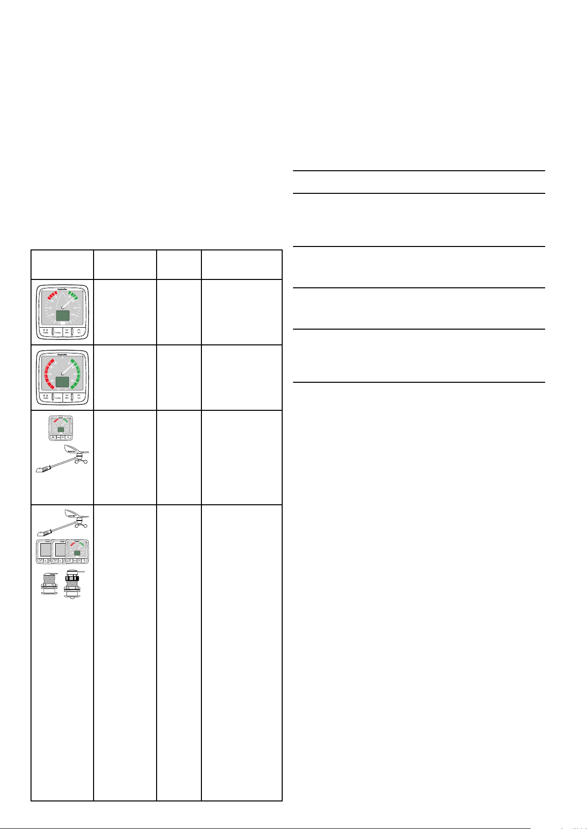
3.2Compatibletransducers
Installationincludesthefollowingactivities:
InstallationTask
1Planyoursystem.
2
Obtainallrequiredequipmentandtools.
3
Siteallequipment.
4Routeallcables.
5
Drillcableandmountingholes.
6Makeallconnectionsintoequipment.
7
Secureallequipmentinplace.
8Poweronandtestthesystem.
Schematicdiagram
Aschematicdiagramisanessentialpartofplanning
anyinstallation.Itisalsousefulforanyfuture
additionsormaintenanceofthesystem.The
diagramshouldinclude:
•Locationofallcomponents.
•Connectors,cabletypes,routesandlengths.
InstrumentWindVanetransducer
Thewindvanetransducerslistedbeloware
compatiblewiththefollowinginstrumentdisplays:
•i60Wind
•i70viaiTC-5converter
Part
numberImageHousingMounting
E22078
E22079Longarmwind
Shortarm
windvane
vane
InstrumentRotavectatransducer
Thewindtransducerslistedbelowarecompatible
withthefollowinginstrumentdisplays:
•i40Wind
•i60Wind
•i70viaiTC-5converter
Surfacemount
Surfacemount
Part
numberImageHousingMounting
Z195Rotavecta
transducer
Surfacemount
16i60
Page 17

3.3Typicalsystems
S
S
M
M
A
A
R
R
T
T
P
P
I
I
L
L
O
O
T
T
D1237 3-1
12 V / 24 V dc
12 V dc
SeaTalk
ng
1 2
6
10 11
8 9
5
7
3
4
TheinstrumentrangecanbeconnecteddirectlytoaSeaTalk
connectedtoaSeaT alksystemusingtheSeaT alktoSeaTalk
BasicSeaT alk
1
2
ng
systemexample
SeaTalk
SeaTalk
ng
network.Theinstrumentrangecanalsobe
ng
adaptorcable.
ng
instrumentdisplay
ng
pilotcontroller
3i60Windinstrument
4Raymarinewindvanetransducer
5
6
7
8
9i50Depthinstrument
10
11Depthtransducer
Raymarinemultifunctiondisplay
12/24Vdcpowersupply
Raymarinecoursecomputer(providing12Vdcpowersupply
totheSeaTalk
i50Speedinstrument
Speedtransducer
ng
network.)
Planningtheinstallation
17
Page 18

ExtendedSeaT alk
S
S
M
M
A
A
R
R
T
T
P
P
I
I
L
L
O
O
T
T
12 V
D1237 4-1
10
12
11 11
1 2 2 3 4 5
17
6 7 8
16
9
11
1514
13
18 19
ng
systemexample
1
2
3Fluxgatecompass
4
5
6
7
8
9Manoverboard
10
11
12
13
14i60Windinstrument
15i50Depthinstrument
16
SeaTalk
SeaTalk
Rudderreference
Raymarinecoursecomputer(providing12Vdcpowersupply
toSeaTalk
12/24Vdcpowersupply
RaymarineAIStransceiver
RaymarineSeaTalk
SeaTalktoSeaT alk
SeaTalk
Raymarinemultifunctiondisplay
Enginedata(viadevicenetadaptorcable.)
i50Speedinstrument
ng
pilotcontroller
ng
instrumentdisplays
ng
network.)
ng
GPS
ng
converter
ng
5wayblocks
17Raymarinewindvanetransducer
18Depthtransducer
19
18i60
Speedtransducer
Page 19

3.4Systemprotocols
D1253 0-1
3
4
2
1
5
3.5Toolsrequired
Yourproductcanbeconnectedtovariousproducts
andsystemstoshareinformationandsoimprove
thefunctionalityoftheoverallsystem.These
connectionsmaybemadeusinganumberof
differentprotocols.Fastandaccuratedatacollection
andtransferisachievedbyusingacombinationof
thefollowingdataprotocols:
•SeaT alk
ng
•NMEA2000
•SeaT alk
Note:Y oumayndthatyoursystemdoesnot
usealloftheconnectiontypesorinstrumentation
describedinthissection.
Seatalk
SeaTalk
ng
ng
(NextGeneration)isanenhancedprotocol
forconnectionofcompatiblemarineinstruments
andequipment.ItreplacestheolderSeaT alkand
SeaTalk
SeaTalk
2
protocols.
ng
utilizesasinglebackbonetowhich
compatibleinstrumentsconnectusingaspur.Data
andpowerarecarriedwithinthebackbone.Devices
thathavealowdrawcanbepoweredfromthe
network,althoughhighcurrentequipmentwillneed
tohaveaseparatepowerconnection.
SeaTalk
ng
isaproprietaryextensiontoNMEA2000
andtheprovenCANbustechnology.Compatible
NMEA2000andSeaTalk/SeaTalk
2
devicescan
alsobeconnectedusingtheappropriateinterfaces
oradaptorcablesasrequired.
Toolsrequiredforinstallation
1Pozi-drivescrewdriver
2File
3
92mm(3.62in)holecutter
4Adhesivetape
5
Powerdrill
NMEA2000
NMEA2000offerssignicantimprovementsover
NMEA0183,mostnotablyinspeedandconnectivity.
Upto50unitscansimultaneouslytransmitand
receiveonasinglephysicalbusatanyonetime,
witheachnodebeingphysicallyaddressable.The
standardwasspecicallyintendedtoallowfor
awholenetworkofmarineelectronicsfromany
manufacturertocommunicateonacommonbusvia
standardizedmessagetypesandformats.
SeaTalk
SeaTalkisaprotocolwhichenablescompatible
instrumentstoconnecttoeachotherandsharedata.
TheSeaT alkcablesystemisusedtoconnect
compatibleinstrumentsandequipment.Thecable
carriespoweranddataandenablesconnection
withouttheneedforacentralprocessor.
Additionalinstrumentsandfunctionscanbeaddedto
aSeaTalksystem,simplybypluggingthemintothe
network.SeaTalkequipmentcanalsocommunicate
withothernon-SeaT alkequipmentviatheNMEA
0183standard,providedasuitableinterfaceisused.
Planningtheinstallation
19
Page 20

3.6Selectingadisplaylocation
Dxxxxx-1
70°
70°
70°
70°
Warning:Potentialignitionsource
ThisproductisNOTapprovedforusein
hazardous/ammableatmospheres.Do
NOTinstallinahazardous/ammable
atmosphere(suchasinanengineroom
ornearfueltanks).
Generallocationrequirements
Whenselectingalocationfortheunititisimportant
toconsideranumberoffactors.
Ventilationrequirements
Toprovideadequateairow:
•Ensurethatequipmentismountedina
compartmentofsuitablesize.
•Ensurethatventilationholesarenotobstructed.
•Ensureadequateseparationofequipment.
Mountingsurfacerequirements
Viewingangle
Ensureunitsareadequatelysupportedonasecure
surface.DoNOTmountunitsorcutholesinplaces
whichmaydamagethestructureofthevessel.
Cableroutingrequirements
Ensuretheunitismountedinalocationwhichallows
properroutingandconnectionofcables:
•Minimumcablebendradiusof100mm(3.94in)is
requiredunlessotherwisestated.
•Usecablesupportstopreventstresson
connectors.
Electricalinterference
Selectalocationthatisfarenoughawayfrom
devicesthatmaycauseinterference,suchas
motors,generatorsandradiotransmitters/receivers.
Magneticcompass
Whenchoosingasuitablelocationyoushouldaim
tomaintainthemaximumpossibledistancebetween
theunitandanycompasses.
Topreventpotentialinterferencewiththevessel's
magneticcompasses,ensurethataminimum
distanceof230mm(9in)betweentheunitandany
installedcompassesismaintained.
Viewingangleconsiderations
Asdisplaycontrast,colorandnightmode
performanceareallaffectedbytheviewingangle,
Raymarinerecommendsyoutemporarilypowerup
thedisplaywhenplanningtheinstallation,toenable
youtobestjudgewhichlocationgivestheoptimum
viewingangle.
20i60
Page 21

3.7Productdimensions
D1238 9-1
A C G
D E
B
F
A
B
C14mm(0.55”)
D
110mm(4.22”)
115mm(4.52”)
30mm(1.18”)
3.8Windvanetransducer/rotavecta locationrequirements
Whenselectingalocationforyourwindtransducerit
isimportanttoconsideranumberoffactors.
Thetransducer'slocationmust:
•Allowreasonableaccessforinstallationand
servicing.
•Beashighaspossibleandawayfromany
equipmentwhichmayshieldthetransduceror
otherwisedisturbtheairow.
•Provideahorizontalmountingsurface.Ifasurface
(e.g.masttop)isotherwisesuitablebutnot
horizontal,makeupasuitablewedgedpacking
piecetoprovidethenecessaryhorizontalsurface.
•Theremustalsobeaviablerouteforthe
transducercabletoberoutedtotheproductitisto
beconnectedto(i.e.displayorconverter).
E
F
G17mm(0.67”)
35mm(1.38”)
90mm(3.54”)
Windvanetransducerandrotavecta
mounting
Ensurethatthewindtransducerorrotavectais
installedinaccordancewiththeinstructionssupplied
withtheunit.
Planningtheinstallation
21
Page 22

22
i60
Page 23

Chapter4:Cablesandconnections
Chaptercontents
•4.1Generalcablingguidanceonpage24
•4.2Powerconnectiononpage24
•4.3SeaT alk
•4.4Transducerconnectionsonpage26
•4.5iTC-5connectiononpage26
•4.6SeaT alkconnectiononpage27
•4.7NMEA2000connectiononpage28
ng
connectionsonpage25
Cablesandconnections23
Page 24

4.1Generalcablingguidance
100 mm (4 in)
200 mm (8 in)
+
_
D13137-1
2
1
4
3
SeaTalk
ng
D12391-2
1 2
8
6
3 54
7
12 V dc
4.2Powerconnection
Cabletypesandlength
Itisimportanttousecablesoftheappropriatetype
andlength
•Unlessotherwisestateduseonlystandardcables
ofthecorrecttype,suppliedbyRaymarine.
•Ensurethatanynon-Raymarinecablesareofthe
correctqualityandgauge.Forexample,longer
powercablerunsmayrequirelargerwiregauges
tominimizevoltagedropalongtherun.
Routingcables
Cablesmustberoutedcorrectly,tomaximize
performanceandprolongcablelife.
•DoNOTbendcablesexcessively.Wherever
possible,ensureaminimumbenddiameterof200
mm(8in)/minimumbendradiusof100mm(4in).
PowerissuppliedtotheproductovertheSeaT alk
network.
ASeaTalk
connectedtotheSeaT alk
ng
systemrequiresone12Vdcsupply ,
ng
backbone.Thiscanbe
provided:
•Byabatteryviathedistributionpanel,or
•FromaRaymarinecoursecomputer,viaaSeaT alk
oraSeaT alk
ng
system.
Warning:Groundingnotrequired
Thisproductisfullyinsulatedanddoes
NOTrequireseparategrounding.
Warning:Positivegroundsystems
Donotconnectthisunittoasystemwhich
haspositivegrounding.
Powerconnection
Directpowerconnection
ng
•Protectallcablesfromphysicaldamageand
exposuretoheat.Usetrunkingorconduitwhere
possible.DoNOTruncablesthroughbilgesor
doorways,orclosetomovingorhotobjects.
•Securecablesinplaceusingtie-wrapsorlacing
twine.Coilanyextracableandtieitoutoftheway.
•Whereacablepassesthroughanexposed
bulkheadordeckhead,useasuitablewatertight
feed-through.
•DoNOTruncablesneartoenginesoruorescent
lights.
Alwaysroutedatacablesasfarawayaspossible
from:
•otherequipmentandcables,
•highcurrentcarryingacanddcpowerlines,
•antennae.
Strainrelief
Ensureadequatestrainreliefisprovided.Protect
connectorsfromstrainandensuretheywillnotpull
outunderextremeseaconditions.
Cableshielding
1
3Acircuitbreakerorfuse
212Vdcvesselpowersupply
3Vessel’sRFground
4
SeaTalk
ng
powercable
Example
Ensurethatalldatacablesareproperlyshielded
thatthecableshieldingisintact(e.g.hasn’tbeen
scrapedoffbybeingsqueezedthroughatightarea).
24
1
2
SeaTalk
SeaTalk
ng
instrument
ng
Pilotcontroller
312Vdcvesselpowersupply.
i60
Page 25

4
D1205 6-1
12Vdcpositive(+)
4.3SeaTalk
ng
connections
5
6
7
In-line5Afuse
SeaTalk
ng
powercable
12Vdcnegative(-)
8Vessel’sRFground
SeaTalk
ng
powerprotection
Thepowersupplymustbeprotectedbya5Afuse
oracircuitbreakerprovidingequivalentprotection.
Raymarinerecommendsthatthepowerisconnected
toaSeaTalk
ng
systeminsuchawaythatthecurrent
drawnoneachsideofthepowerconnectionpoint
isequal.
SeaTalk
ng
powercables
PartnumberDescription
A06049
SeaTalk
ng
powercable
Theunithas2xSeaT alk
connectingtoaSeaT alk
ng
connectorsontherearfor
ng
network.
ConnectingSeaTalk
ng
cables
1.Rotatethelockingcollaronthebackoftheunitto
theUNLOCKEDposition.
2.Ensurethespurcableendconnectoriscorrectly
oriented.
3.Fullyinsertthecableconnector.
4.Rotatelockingcollarclockwise(2clicks)untilit
snapsintotheLOCKEDposition.
Cablesandconnections25
Page 26

4.4Transducerconnections
6
7
3
4
5
D1239 6-1
1
2
3 mm
6 mm
50 mm
1
2
D1235 9-1
12 V
D1203 3-3
1 2 3 4
5
6 7 8
4.5iTC-5connection
Transducerconnectionsonlyapplytothei60Wind
instrument,thei60Closehauledwinddoesnot
includetransducerconnectionsasitisarepeater
display.
i60transducerconnections
1BlueRotor+
(Rotavecta)
2RedRotor–
(Rotavecta)
TransducerscanbeconnectedtoaSeaT alk
networkusingRaymarine'sInstrumenttransducer
converter(iTC-5)andani70instrument,thedata
canthenberepeatedonani50/i60unit.
ng
3
GreyWind0V(Shield)
4YellowAnemometer
(signal)
5
Blue
Cosinewind
direction
6
7
GreenSinewinddirection
RedWindV+
Note:Connectors1and2arerotavecta
connections,connectors3to7areforwind
transducers.
Makingtransducerconnections
Althoughthetransducercableisttedwithspade
connectorsfordirectconnectiontotherearofthe
unit,itmaybenecessarytoremovethesetofacilitate
installation,e.g.ifthecablehastoberoutedthrough
narrowapertures.1/8thspadeterminalswillbe
required(notsupplied),toreplacethoseremoved.
Whenttingthenewspadeconnectors,preparethe
cablesasdetailedbelow:
1
2
3
4
5
i50Depth(Repeater)
i70Instrument(Master)
i50Speed(Repeater)
i60Wind(Repeater)
iTC-5
6Depthtransducer
7
8
Windvanetransducer
Speedtransducer
Note:TransducersconnectedtotheiTC-5mustbe
calibratedusingani70(master)unit.Transducers
connectedtotheiTC-5cannotbecalibratedusing
ani50/i60.
MakingiTC-5transducerconnections
Forinstructionsonconnectingtransducerstoyour
iTC-5refertotheiTC-5handbook.
1.Preparethecableasshownin1above.
2.Foldbackthewirestrandsandinsertintothenew
spadeconnectorasshownin2above.
3.Ensurethewirestrandsdonotextendbeyond
therearofthespadeconnectorinsulation.
4.Crimptheconnectortothewire.
26i60
Page 27

4.6SeaTalkconnection
12 V dc
12 / 24 V dc
D1205 8-2
98
11 12
4
1 2 3
7
5
6 6 7
10
SeaTalkpowercables
ConnectionstoanexistingSeaT alksystemmustbe
madeusingaSeaTalktoSeaTalk
ng
adaptorcable.
BasicSeaTalksystemexample
PartnumberDescription
D229
SeaTalkpowercable.
1i70Instrumentdisplay
(SeaTalk
2
i50Speedinstrument
(SeaTalk
3i50Depthinstrument
(SeaTalk
4Raymarinewindvane
transducer
5
i60Windinstrument
(SeaTalk
6
7
SeaTalk
SeaTalktoSeaTalk
cables
8
Speedtransducer
9Depthtransducer
10
11
12/24Vdcpowersupply
SeaTalkCoursecomputer
(providing12Vdcpowerto
SeaTalknetwork.)
ng
)
ng
)
ng
)
ng
)
ng
cables
ng
adaptor
12
ST6002pilotcontroller
(SeaTalk)
SeaTalkpowerprotection
Thepowersupplymustbeprotectedbya5Afuse
oracircuitbreakerprovidingequivalentprotection.
Raymarinerecommendsthatthepowerisconnected
toaSeaT alksysteminsuchawaythatthecurrent
drawnoneachsideofthepowerconnectionpoint
isequal.
Cablesandconnections
27
Page 28

4.7NMEA2000connection
12V NMEA 2000
SeaTalk
ng
D1238 0-1
3
1
2
4
D123 77-1
1
4
2
3
Youcaneither:
•UseyourSeaTalk
NMEA2000deviceonaspur,OR
•connecttheinstrumentdisplayonaspurintoan
existingNMEA2000backbone.
Important:Y oucannothaveany2terminated
backbonesconnectedtogether,unlessyouhave
anisolationgatewaybetweenthetwobackbones.
ng
backboneandconnecteach
ConnectingNMEA2000equipmenttothe
SeaTalk
ng
backbone
1.12Vdcpowersupplyintobackbone.
2.SeaTalk
3.SeaTalk
ng
backbone.
ng
toDeviceNetadaptorcable.
4.NMEA2000equipment.
ConnectingtheunittoanexistingNMEA2000
(DeviceNet)backbone
1.SeaTalk
2.SeaTalk
3.DeviceNetbackbone.
4.NMEA2000equipment.
28i60
ng
instrumentdisplay
ng
toDeviceNetadaptorcable.
Page 29

Chapter5:Mounting
Chaptercontents
•5.1Mountingonpage30
•5.2Frontbezelonpage31
Mounting
29
Page 30

5.1Mounting
D1237 9-1
Pre-mountingcheck
Theproductisdesignedtobesurfacemounted.
Beforemountingtheunit,ensureyouhave:
•Selectedasuitablelocation.
•Identiedthecableconnectionsandroutethatthe
cableswilltake.
•Detachedthefrontbezel.
•Removethekeypadmat.
Mountingdiagram
Note:Thesuppliedgasketprovidesaseal
betweentheunitandasuitablyatandstiff
mountingsurfaceorbinnacle.Thegasketshould
beusedinallinstallations.Itmayalsobe
necessarytouseamarine-gradesealantifthe
mountingsurfaceorbinnacleisnotentirelyatand
stifforhasaroughsurfacenish.
Mountinginstructions
1.Checktheselectedlocationfortheunit,aclear,
atareawithsuitableclearancebehindthepanel
isrequired.
2.Fixthemountingtemplatesuppliedwiththe
product,totheselectedlocation,usingmasking
orselfadhesivetape.
3.Ifpossibleuseanappropriatesizeholecutting
sawandcutoutthecentreholecutoutareaas
indicatedonthemountingtemplate,or
4.Usingasuitableholecuttingsaw,makepilot
holesineachcornerofthecutoutareaandusing
ajigsawcutalongtheinsideedgeofthecutout
line.
5.Ensurethattheunittsintotheremovedarea
andthenlearoundthecutedgeuntilsmooth.
6.Drillanyrequiredholesasindicatedonthe
mountingtemplateforthesecuringscrews.
7.Connecttherelevantcablestotheunit.
8.Peelthebackingoffofthesuppliedgasketand
placetheadhesivesideofthegasketontothe
displayunitandpressrmlyontotheange.
9.Slidetheunitintoplaceandsecureusingthe
screwsprovided.
10.Retkeypadmatandfrontbezel.
Note:Drill,tapsizeandtighteningtorquesare
dependantuponthematerialtypeandthickness
ofthemountingsurface.
30i60
Page 31

5.2Frontbezel
D1237 2-1
1 2
3 4
Removingthefrontbezel
Note:Usecarewhenremovingthebezel.Donot
useanytoolstoleverthebezel,doingsomay
causedamage.
1.Usingyourngerspullthebezelawayfromthe
unitatthetopandside,asshownin2.
Thebezelwillstarttocomeawayfromtheunitat
thetopandside.
2.Nowpullthebezelawayfromtheunitonthe
oppositeside,asshownin3.
Thebezelwillnowcomefreefromtheunit,as
shownin4.
Mounting
31
Page 32

32i60
Page 33

Chapter6:Gettingstarted
Chaptercontents
•6.1Controlsonpage34
•6.2Poweronpage34
•6.3Datamasteronpage35
Gettingstarted
33
Page 34

6.1Controls
TackTrue/AppDisplay VMG
D13138-1
1 2 3 4
6.2Power
Poweringontheunit
Withpowertotheunitturnedonbuttheunitswitched
off:
1.PressandholdthePowerbuttonuntiltheunit
powersonanddataisdisplayed(approximately
2seconds).
Note:Whenpowertotheunitisturnedontheunit
willswitchonautomatically.
Poweringofftheunit
1.PressandholdthePowerbuttonuntilthepower
countdowntimerisdisplayedandreacheszero
(approximately6to8seconds).
1
Display/Power—SelecttoaccessDepth
informationonthedigitaldisplay,adjust
backlight,adjustcontrastandpowerthe
displayOnandOff
2
True/App—Switchbetweentrueand
Calibrationalert
IftheCALlegendonthedigitaldisplayashesfor
therst30secondsafterpowerup,refertothe
Calibrationsectiontocalibrateyourunit.
apparentwinddirection
3
VMG/Down—DisplayVelocitymadegood.
Usetomovedownthroughmenuoptionsorto
decreasenumericvalues
4
Tack/Up—Tackheading.Usetomoveup
throughmenuoptionsortoincreasenumeric
values
34i60
Page 35

6.3Datamaster
10
15
20
25
30
35
40
45
50
55
60
5
4
+
D12492-2
CAL
CAL
Display
Display
True/App
Whereasystemcontainsmorethanoneunit
capableofdisplayingadatatype,theunitphysically
connectedtothetransducermustbesetasthedata
masterandanyotherunitssetasarepeater.
Checkingthesoftwareversionand
instrumentstatus
Youcanchecktheinstrumentdisplay’ssoftware
versionandstatusbyfollowingthestepsbelow.
Note:Thei60CHWindinstrumentisarepeater
display.Y oucannotcheckorchangethe
instrumentstatusofani60CHWinddisplay
Fromthesoftwareversionpage:
Duringnormaloperation:
1.PressandholdtheDisplayandTrue/App
buttonsatthesametimeforapproximately4
seconds,untiltheSoftwareVersionpageis
displayed.
2.PresstheDisplaybuttontoshowtheInstrument
Statuspage.
Theinstrumentstatusisdisplayed(r0=master
andr1=repeater).
Note:TheSoftwareVersionandInstrumentStatus
pagesaretemporarypagesandwilltime-out
automaticallyafter8secondsofinactivity.
Gettingstarted
35
Page 36

36i60
Page 37

Chapter7:Calibration
Chaptercontents
•7.1Usercalibrationonpage38
•7.2Intermediatecalibrationonpage39
•7.3Dealercalibrationonpage39
Calibration37
Page 38

7.1Usercalibration
x 2
D12415-2
+
D12488-2
10
15
20
25
30
35
40
45
50
55
60
5
2
Display
True/App
D12489-2
Display
D12490-2
VMG Tac k
D12491-2
Display
Thei60CHinstrumentdisplayisarepeaterdisplay
andassuchdoesnotrequirecalibration,thesteps
belowapplytothecalibrationofthei60Wind
instrumentonly .
Usercalibrationoptionsinclude:
•Windangleoffset—Assignsanoffsettothewind
anglereadings.
•UnitsforWindspeedreadings—Assignstheunit
ofmeasureusedforwindspeedrelatedreadings
AutomaticLinearization
Thewindtransducercanlinearizeitselfautomatically
undercertainconditions.
ForAutomaticLinearizationtobeperformedCAL
mustbeashingonthedigitaldisplay.CALis
displayedforapproximately30secondsafterpower
onunderthefollowingconditions:
2.Sailyourvesseldirectlyintothewindandadjust
theanalogpointertozero,usingtheVMGand
Tackbuttons.
TheVMGbuttonwilldecreasethecurrentvalue
andtheTackbuttonwillincreasethecurrent
value.Asyoudothis,thewindangleoffset
showstheamountofcorrectionyouhaveapplied.
3.T oexittheUserCalibrationMenuatanytime
pressandholdtheDisplayandTrue/App
buttonsatthesametimeforapproximately2
seconds.
Selectingtheunitofmeasureforwindspeed
readings
•Atrstpoweron,afterinstallation
•Atpoweron,afterafactoryreset.
Toperformtheautomaticlinearizationthevesselwill
needtobeunderway ,withsufcientspacetoturnin
largecirclesunhindered.Thewindspeedmustbe
sufcienttoholdthevanetowindwhilstthevesselis
turning.Thevesselmustbeturnedslowlythroughat
least2completecircles.
Thisprocedureautomaticallylinearizesthewind
vane.Asuccessfullinearizationisindicatedbythe
digitaldisplayashingandabuzzersoundingthree
beeps
AccessingtheUserCalibrationMenu
TheUserCalibrationMenucanbeaccessedby
followingthestepsbelow.
Duringnormaloperation:
1.PressandholdtheDisplayandTrue/App
buttonsatthesametimeforapproximately
2seconds,untiltheUserCalibrationpageis
displayed.
FromtheUserCalibrationMenu:
1.PresstheDisplaybuttonuntiltheWindSpeed
Unitspageisdisplayed(2pressesfromtheUser
Calibrationpage).
2.UsetheVMGorT ackbuttonstoselectthe
requiredunitofmeasureforwindspeedreadings.
Theavailableunitsofmeasureforwindspeed
are:
•KTS(default)—Knots
•M/S—Meterspersecond
3.T oexittheUserCalibrationpagesatanytime
pressandholdtheDisplayandTrue/App
buttonsatthesametimeforapproximately2
seconds.
Aligningthewindtransducer
FromtheUserCalibrationMenu:
1.PresstheDisplaybuttonuntiltheWindAngle
Offsetpageisdisplayed(1pressfromtheUser
Calibrationpage).
38i60
Page 39

7.2Intermediatecalibration
10
15
20
25
30
35
40
45
50
55
60
5
4
+
D12492-2
CAL
CAL
Display
Display
True/App
10
15
20
25
30
35
40
45
50
55
60
5
4
+
D12492-2
CAL
CAL
Display
Display
True/App
10
15
20
25
30
35
40
45
50
55
60
5
14
+
D12493-2
CAL
Display
True/App
+
D12494-2
CAL
CAL
VMG
Tack
7.3Dealercalibration
Intermediatecalibrationallowsyouto:
•Checkinstrumentsoftwareversion
•*Checktheinstrumentstatus(eithermasteror
repeater)
Note:*Notavailableoni60CHWind.
Checkingthesoftwareversionand
instrumentstatus
Youcanchecktheinstrumentdisplay’ssoftware
versionandstatusbyfollowingthestepsbelow.
Note:Thei60CHWindinstrumentisarepeater
display.Y oucannotcheckorchangethe
instrumentstatusofani60CHWinddisplay
Fromthesoftwareversionpage:
Thedealercalibrationproceduresinclude:
•UsercalibrationmenuaccessOn(default)andOff.
•DisplayResponseforwindanglereadings—
Dictatestherateatwhichtheinstrumentdisplay
respondstochangesinwindangledata.
•DisplayResponseforwindspeedreadings—
Dictatestherateatwhichtheinstrumentdisplay
respondstochangesinwindspeeddata.
•DisplayResponseforVMGreadings—Dictates
therateatwhichtheinstrumentdisplayresponds
tochangesinVMGdata.
•*BoatshowmodeOnandOff(default)(Boat
showmodeisonlyavailableondisplayssetas
repeaters).
•Resettofactorydefaults.
Note:Notavailableonthei60CHwindinstrument.
AccessingtheDealerCalibrationMenu-i60
Duringnormaloperation:
1.PressandholdtheDisplayandTrue/App
buttonsatthesametimeforapproximately14
seconds,untiltheDealerCalibrationpageis
displayed.
Note:ToexittheDealerCalibrationpagesatany
Duringnormaloperation:
1.PressandholdtheDisplayandTrue/App
time,pressandholdtheDisplayandTrue/App
buttonsatthesametimeforapproximately2
seconds.
buttonsatthesametimeforapproximately4
seconds,untiltheSoftwareVersionpageis
displayed.
2.PresstheDisplaybuttontoshowtheInstrument
Statuspage.
Theinstrumentstatusisdisplayed(r0=master
andr1=repeater).
SettingaccesstotheUserCalibrationMenu
-i60
FromtheDealerCalibrationpage:
1.PresstheVMGandTackbuttonsatthesame
timetodisplaytheUserCalibrationMenu
Accesspage.
Note:TheSoftwareVersionandInstrumentStatus
pagesaretemporarypagesandwilltime-out
automaticallyafter8secondsofinactivity.
2.UsetheVMGorTackbuttonstoswitchaccessto
theUserCalibrationMenuOnandOff.
•UC1(default)—UserCalibrationmenu
enabled
•UC0—UserCalibrationmenudisabled
Note:ToexittheDealerCalibrationpagesatany
time,pressandholdtheDisplayandTrue/App
buttonsatthesametimeforapproximately2
seconds.
SettingtheresponsedelayforWindAngle
readings
Calibration39
FromtheUserCalibrationMenuAccesspage:
Page 40

1.PresstheDisplaybuttonuntiltheWindAngle
D12495-2
CAL
Display
D12496-2
CAL
Display
D12497-2
CAL
VMG
Display
D12498-2
CAL
KTS
Display
D12500-2
CAL
Display
D12501-2
CAL
Display
Responsepageisdisplayed(1pressfromthe
UserCalibrationAccessMenupage).
2.UsetheVMGandTackbuttonstosetthe
requiredlevelforWindAngleResponse.
Thedefaultlevelis12.Thelevelsavailableare1
to15withlevel1beingtheslowestupdaterate
andlevel15thequickest.
SettingthewindspeedCalibrationFactor
Ifyoundthatyourwindspeedreadingsdeviatefrom
areferencedwindspeedsourcethenaCalibration
Factorcanbeappliedtoreducethedeviation.
FromtheUserCalibrationMenuAccesspage:
1.PresstheDisplaybuttonuntiltheCurrentWind
Speedpageisdisplayed(4pressesfromthe
UserCalibrationMenuAccesspage).
Note:ToexittheDealerCalibrationpagesatany
time,pressandholdtheDisplayandTrue/App
buttonsatthesametimeforapproximately2
seconds.
SettingtheresponsedelayforWindSpeed
readings
FromtheUserCalibrationMenuAccesspage:
1.PresstheDisplaybuttonuntiltheWindSpeed
Responsepageisdisplayed(2pressesfromthe
UserCalibrationAccessMenupage).
2.UsetheVMGandTackbuttonstosetthe
requiredlevelforWindSpeedResponse.
Thedefaultlevelis12.Thelevelsavailableare1
to15withlevel1beingtheslowestupdaterate
andlevel15thequickest.
Note:ToexittheDealerCalibrationpagesatany
time,pressandholdtheDisplayandTrue/App
buttonsatthesametimeforapproximately2
seconds.
2.UsetheVMGandTackbuttonstoadjustthe
CalibrationFactortothedesiredvalue.
WhentheVMGandTACKbuttonsarenot
beingpressedthescreenwillrevertbackto
CurrentWindSpeedpagetoenableyoutosee
whatchangetheCalibrationFactorhasonthe
display’sWindSpeedreading.
Note:Toexitthedealercalibrationpagesatany
timepressandholdtheDisplayandTrue/App
buttonsatthesametimeforapproximately2
seconds.
EnablinganddisablingBoatShowMode-i60
FromtheUserCalibrationMenuAccesspage:
1.PresstheDisplaybuttonuntiltheBoatShow
Modepageisdisplayed(5pressesfromtheUser
CalibrationMenuAccesspage).
2.UsetheVMGorT ackbuttonstoswitchtheBoat
ShowModeOnandOff(default).
SelectingOnwillputthedisplayintoboatshow
mode.
SettingtheresponsedelayforVMGreadings
FromtheUserCalibrationMenuAccesspage:
Note:Boatshowmodeisonlysuitablefor
demonstrationpurposesandshouldNOTbeused
whilstyourvesselisinuse.
1.PresstheSpeedbuttonuntiltheVMGResponse
pageisdisplayed(3pressesfromUser
CalibrationMenuAccesspage).
Note:Toexitthedealercalibrationpagesatany
timepressandholdtheDisplayandTrue/App
buttonsatthesametimeforapproximately2
seconds.
2.UsetheVMGorTackbuttonstosettherequired
levelforVMGresponse.
Thedefaultlevelis12.Thelevelsavailableare1
to15withlevel1beingtheslowestupdaterate
andlevel15thequickest.
Resettingthedisplaytofactorydefaults-i60
FromtheUserCalibrationMenuAccesspage:
1.PresstheDisplaybuttonuntiltheFactoryReset
pageisdisplayed(5pressesfromtheUser
CalibrationMenuAccesspage).
Note:ToexittheDealerCalibrationpagesatany
time,pressandholdtheDisplayandTrue/App
buttonsatthesametimeforapproximately2
seconds.
2.T oresetthedisplaytofactorydefaultsettings:
i.UsetheVMGorTackbuttonstochangethe
resetoptiontoF1(default).
40i60
ii.PresstheDisplaybuttontoresetyourdisplay
tofactorydefaultsettings.
Page 41

Note:Toexitthedealercalibrationpagesatany
timepressandholdtheDisplayandTrue/App
buttonsatthesametimeforapproximately2
seconds.
Calibration
41
Page 42

42
i60
Page 43

Chapter8:Usingyourdisplay
Chaptercontents
•8.1Pagesonpage44
•8.2i60Windoperationonpage44
•8.3Illuminationonpage46
Usingyourdisplay
43
Page 44

8.1Pages
HI
LO
disp
KTS
KTS
KTS
LO
KTS
KTS
Display
Display
DisplayDisplay
Display
Display
Display
Tack
10
15
20
25
30
35
40
45
50
55
60
5
3
D12552-2
8.2i60Windoperation
Thepagesavailabledependonthedisplayvariant
andareshowninthetablebelow:
i60Windi60Closehauledwind
WindspeedWindspeed
*Beaufortwindspeed*Maximumwindspeed
*MaximumwindspeedVMG
*Maximumtruewindspeed
Tack
alarm
*Lowtruewindspeedalarm
*Highapparentwindangle
alarm
*Lowapparentwindangle
alarm
VMG
Tack
Note:*Thesepagesaretemporarypagesandwill
time-outtothepreviouspermanentpageafter8
secondsofinactivity.
Whenconnectedtoarelevantrotavectaorwind
vanetransducerthei60provides:
•Trueandapparentwinddirectionandspeed.Wind
speedisdisplayedeitherinknots,metersper
secondorasBeaufortscalevalues.
•Velocitymadegood(VMG)information,when
vesselspeedinformationisavailableonthe
network.
•T ackangle,whenheadinginformationisavailable
onthenetwork.
•Maximumwindspeed.
•Highandlowtruewindspeedalarms.
•Highandlowapparentwindanglealarms.
Note:Alarmsareonlyavailableonthei60
Windinstrument,whensetasamasterunit.No
alarmsareavailableonthei60Closehauledwind
instrument.
i60displayinformation
Thei60instrument'sdisplayconsistsofananalogue
pointeranddigitaldisplay.
Changingpages
Duringnormaloperation:
1.PresseithertheDisplaybuttontocyclethrough
thewindpages.
2.PresstheVMGbuttontodisplayVMG
information.
3.PresstheTackbuttontodisplaytackinformation.
Analoguedisplay
Theanaloguedisplaypointershowseithertrueor
apparentwinddirection(Dependingonsetting).
Digitaldisplay
ThedigitaldisplayLCDshowsthefollowingwind
information.
•Beaufortwindspeed
•True/apparentwindspeed
•Velocitymadegood(VMG)
•T ackheading
•Maximumwindspeed
•Windalarmdata
Usingthedisplaybutton
44
Duringnormaloperation:
i60
Page 45

1.UsetheDisplaybuttontocyclethroughthe
TACK
VMG
KTS
TackTrue/AppDisplay VMG
1
2
D12550-2
D13142-1
3
1
2
D12551-2
1
2
availablepages.
2.PressandholdtheT ackbuttonfor3seconds
toresetthemaximumwindspeedtothecurrent
windspeedvalues.
Note:AllpagesexceptfortheCurrentwind
speedpagearetemporaryandwilltime-outafter
8seconds.
UsingTackandVMGbuttons
2.Windangle(speciedindegrees)
TrueWindAngle(TWA)—Theanglebetween
theTWDandthecenterlineofthevessel.
ApparentWindAngle(AWA)—Theangle
betweentheAWDandthecenterlineofthe
vessel.
3.Windspeed(speciedinthechosenspeedunits)
TrueWindSpeed(TWS)—Thespeedthatthe
windwouldappeartobeblowingacrossthe
vesselifitwasnotmakinganyway.
ApparentWindSpeed(AWS)—Thespeed
thatthewindwouldappeartobeblowingacross
thevesselwhenitismakingway.
Note:TrueWindreadingsrequireSpeedThrough
Water(STW)datatobeavailable.
Switchingbetweentrueandapparentwind
information
Duringnormaloperation:
1.PresstheVMGbuttontoshowtheVMGpageon
thedigitaldisplay.
Note:VMGinformationisonlyavailablewhen
vesselspeedinformationisavailable.
2.PresstheTackbuttontoshowtheTackpageon
thedigitaldisplay.
Note:Tackinformationisonlyavailablewhen
vesselheadingandspeedinformationisavailable.
TrueandApparentwind
Windangle,directionandspeedarereportedas
either‘True’or‘Apparent’windmeasurements.
•Truewind—Truewindmeasurementsassume
thevesselismotionlessinthewater.Truewind
readingsarecalculatedusingApparentWindand
STWvalues.
•Apparentwind—Apparentwindisthewindfelt
ondeckwhenthevesselisinmotionwhichis
affectedbyvesselangleandspeed.
Withthevesseltiedalongside,TrueandApparent
windreadingsshouldbeidentical.
YoucanswitchtheunitbetweendisplayingTrueor
Apparentwindinformation.
Duringnormaloperation:
1.PresstheTrue/Appbuttontoswitchbetween
trueorapparentwindinformation.
•InTruemodetheindicatorshownin1above
willbedisplayed.
•InApparentmodetheindicatorshownin2
abovewillbedisplayed.
1.Winddirection(speciedusingcompasspoints)
TrueWindDirection(TWD)—Thecompass
directionthatwindwouldappeartobeblowing
acrossthevesselifitwasnotmakinganyway.
ApparentWindDirection(AWD)—The
compassdirectionthatwindwouldappeartobe
blowingacrossthevesselwhenitismakingway.
Usingyourdisplay
45
Page 46

8.3Illumination
Display
10
15
20
25
30
35
40
45
50
55
60
5
1
VMG
Tack
D13143-1
Adjustingthebacklightlevel
Thebacklightingcanbeadjustedusingthepower
button.
Duringnormaloperation:
1.PressandholdtheDisplaybuttonfor
approximately1seconduntilthebacklightpage
isdisplayed.
Landthecurrentilluminationlevelisdisplayed.
2.UsetheVMGbuttontodecreasetheillumination
level.
3.UsetheTackbuttontoincreasetheillumination
level.
Theilluminationlevelcanbeadjustedfrom
0(default)(Off)to9(Max)
Note:Thebacklightpagewilltime-outafter8
secondsofinactivity.
Adjustingthecontrast—i60
ThecontrastlevelcanbeaccessedusingtheSpeed
button.
Duringnormaloperation:
1.PressandholdtheDisplaybuttonfor
approximately4secondstodisplaytheContrast
page.
Cisdisplayedon-screenandthecurrentcontrast
level.
2.UsetheDisplaybuttontocyclethroughthe
availablecontrastlevels.
Thecontrastlevelcanbeadjustedfromlevel
0(default)to3.
Note:Thecontrastpagewilltime-outafter8
secondsofinactivity.
WhenconnectedonaSeaT alk
ng
networktheunit
canparticipateingroupilluminationandbeassigned
toagroupofunitswhichwillsharetheirbacklighting
levels.Availablegroupsareasfollows:
•OFF(default)—Groupilluminationis
switchedoff
•HL1—Helm1
•HL2—Helm2
•CPt—Cockpit
•FLY—Flybridge
•NST—Mast
•GP1toGP5—Userdenedgroups
Whenassignedtoagroup,whenthebacklightingof
1unitisadjustedthebacklightinglevelofallunits
assignedtothesamegroupwillalsochange.
Assigningtheunittoagroup
Toassigntheunitaspartofagroupsothatitcan
participateingroupilluminationfollowthesteps
below.
Duringnormaloperation:
1.PressandholdtheDisplayandTrue/App
buttonsathesametimeforapproximately6
seconds,untiltheGroupIlluminationpageis
displayed.
GrPisdisplayedon-screen
Note:TheGroupIlluminationpageisatemporary
pageandwilltime-outtothepreviouspageafter
8seconds.
2.PresstheDisplaybuttontodisplaythecurrent
groupilluminationsetting.
3.PresstheVMGandTackbuttonsatthesame
timetochangethecurrentsetting.
Thecurrentgroupsettingwillash.
4.UsetheT ackbuttontocycleupwardsthrough
thelistofavailablegroups.
5.UsetheVMGbuttontocyclebackdownthrough
thelist.
6.PresstheVMGandTackbuttonsatthesame
timetoassignthedisplaytotheselectedgroup.
Thegroupsettingwillstopashing.
7.PressandholdtheDisplayandTrue/App
buttonsathesametimeforapproximately2
secondstoreturntonormaloperation.
Groupillumination
Groupilluminationisusedtosynchronizesand
controlthebacklightinglevelofmultipleunits
assignedtothesamegroup.
Theunitcanparticipateinsharedillumination
viaaSeaT alknetworkorgroupilluminationviaa
ng
SeaTalk
WhenconnectedonaSeaTalknetworkall
network.
compatibleunitswillsharetheirbacklightlevel(when
1unit'sbacklightinglevelisadjustedallotherunits
backlightlevelwillalsochange).
46i60
Page 47

Chapter9:Alarms
Chaptercontents
•9.1Alarmsonpage48
Alarms
47
Page 48

9.1Alarms
KTS
D12553-2
D12554-2
KTS
LO
D12555-2
HI
D12556-2
LO
D12557-2
+
-
+
KTS KTS
VMG
Tack
Tack
VMG
Alarmsalertyoutoasituationorhazardrequiring
yourattention.
Youcansetupalarmstoalertyoutocertain
conditions.
Lowapparentwindanglealarm
Alarmsareraisedbysystemfunctions,andalso
externalequipmentconnectedtoyourdisplay.
Whenanalarmeventoccursanaudibleandvisual
alarmisactivatedwhichindicatesthealarmstate.
Alarmthresholdscanbeconguredfromtherelevant
alarmpage/menu.
Instrumentalarms
Alarmsavailableonthei60Windarelistedbelow.
•Hightruewindspeed
•Lowtruewindspeed
•Highapparentwindangle
•Lowapparentwindangle
Note:Alarmsarenotavailableonthei60Close
Hauledwind.
Alarmindications
Analarmeventisindicatedbybothaudibleand
visualwarnings.
TheLowapparentwindanglealarmsoundswhen
theapparentwindangleisequaltoorlessthanthe
Lowapparentwindanglethreshold.Thealarm
soundsuntilsilencedmanually.
Silencingalarms
1.Pressanybuttontosilenceanactivealarm.
Enabling/Disablingalarms
Alarmscanbeenabledordisabledatanytime.
Withtherelevantalarmpagedisplayed:
1.PressandholdtheTackbuttonfor1secondto
switchthealarmonoroff.
Whenthealarmisonthealarmthresholdis
displayed.
Settingalarmthresholds
Youcanadjustthethresholdatwhichalarmsare
triggeredbyfollowingthestepsbelow.
Hightruewindspeedalarm
TheHightruewindspeedalarmsoundswhenthe
truewindspeedisequaltoormorethantheHigh
truewindspeedthreshold.Thealarmsoundsuntil
silencedmanually .
Lowtruewindspeedalarm
TheLowtruewindspeedalarmsoundswhenthe
truewindspeedisequaltoorlessthantheLow
truewindspeedthreshold.Thealarmsoundsuntil
silencedmanually .
Highapparentwindanglealarm
Withtherelevantalarmpagedisplayed:
1.PresstheVMGandTackbuttonsatthesame
timetoenteradjustmode.
Thecurrentthresholdwillstarttoash.
2.UsetheTackbuttontoincreasethealarm
threshold.
3.UsetheVMGbuttontodecreasethealarm
threshold.
4.PresstheVMGandTackbuttonsatthesame
timetosavethenewalarmthresholdandexit
adjustmode.
Note:Theillustrationaboveisanexample
depictingsettingtheMaximumtruewindspeed
alarmthreshold.
TheHighapparentwindanglealarmsoundswhen
theapparentwindangleequaltoormorethanthe
Highapparentwindanglethreshold.Thealarm
soundsuntilsilencedmanually.
48i60
Page 49

Chapter10:Maintainingyourdisplay
Chaptercontents
•10.1Serviceandmaintenanceonpage50
•10.2Condensationonpage50
•10.3Routineequipmentchecksonpage51
•10.4Cleaningonpage51
•10.5Cleaningthedisplaycaseonpage52
•10.6Cleaningthedisplayscreenonpage52
Maintainingyourdisplay
49
Page 50

10.1Serviceandmaintenance
10.2Condensation
Thisproductcontainsnouserserviceable
components.Pleasereferallmaintenance
andrepairtoauthorizedRaymarinedealers.
Unauthorizedrepairmayaffectyourwarranty .
Certainatmosphericconditionsmaycauseasmall
amountofcondensationtoformontheunit'swindow.
Thiswillnotdamagetheunitandwillclearafterthe
unithasbeenswitchedonforashortperiod.
50i60
Page 51

10.3Routineequipmentchecks
10.4Cleaning
Raymarinestronglyrecommendsthatyoucomplete
anumberofroutinecheckstoensurethecorrectand
reliableoperationofyourequipment.
Completethefollowingchecksonaregularbasis:
•Examineallcablesforsignsofdamageorwear
andtear.
•Checkthatallcablesaresecurelyconnected.
Bestcleaningpractices.
Whencleaningthisproduct:
•DoNOTwipethedisplayscreenwithadrycloth,
asthiscouldscratchthescreencoating.
•DoNOTuseabrasive,oracidorammoniabased
products.
•DoNOTuseajetwash.
Maintainingyourdisplay
51
Page 52

10.5Cleaningthedisplaycase
10.6Cleaningthedisplayscreen
Thedisplayunitisasealedunitanddoesnotrequire
regularcleaning.Ifitisnecessarytocleantheunit,
followthisbasicprocedure:
1.Switchoffthepowertothedisplay.
2.Wipethedisplaywithaclean,softcloth(a
microbreclothisideal).
3.Ifnecessary,useamilddetergenttoremove
greasemarks.
Note:DoNOTusesolventsordetergentsonthe
screenitself.
Note:Incertainconditions,condensationmay
appearinsidethedisplayscreen.Thiswillnot
harmtheunit,andcanbeclearedbypoweringon
thedisplayforashorttime.
Acoatingisappliedtothedisplayscreen.This
makesitwaterrepellent,andpreventsglare.To
avoiddamagingthiscoating,followthisprocedure:
1.Switchoffthepowertothedisplay.
2.Rinsethescreenwithfreshwatertoremoveall
dirtparticlesandsaltdeposits.
3.Allowthescreentodrynaturally.
4.Ifanysmearsremain,verygentlywipethescreen
withacleanmicrobrecleaningcloth(available
fromanopticians).
52i60
Page 53

Chapter11:Troubleshooting
Chaptercontents
•11.1Troubleshootingonpage54
•11.2Instrumenttroubleshootingonpage55
•11.3Poweruptroubleshootingonpage56
•11.4Miscellaneoustroubleshootingonpage57
Troubleshooting
53
Page 54

11.1Troubleshooting
Thetroubleshootinginformationprovidespossible
causesandcorrectiveactionrequiredforcommon
problemsassociatedwithmarineelectronics
installations.
AllRaymarineproductsare,priortopackingand
shipping,subjectedtocomprehensivetestand
qualityassuranceprograms.However,ifyou
experienceproblemswiththeoperationofyour
productthissectionwillhelpyoutodiagnose
andcorrectproblemsinordertorestorenormal
operation.
Ifafterreferringtothissectionyouarestillhaving
problemswithyourunit,pleasecontactRaymarine
TechnicalSupportforfurtheradvice.
54i60
Page 55

11.2Instrumenttroubleshooting
FaultCauseAction
Blankdisplay.Nopowersupply.
SeaTalk/SeaT alk
transferredbetweeninstruments.
AgroupofSeaTalk/SeaTalk
working.
ng
informationnotbeing
SeaTalk/SeaTalk
fault.
ng
unitsnot
SeaTalk/SeaTalk
fault.
•Checkfuse/circuitbreaker.
•Checkpowersupply.
•CheckSeaTalk/SeaTalk
ng
cabling
andconnectorsecurity.
ng
cablingorconnector
•ChecksecurityofSeaTalk/SeaTalk
ng
connectionsbetweenunits.
•CheckconditionofSeaTalk/SeaTalk
ng
cables.
•Isolatefaultyunitbydisconnecting
unitsonebyone.
ng
cablingorconnector
•CheckthesecurityofSeaT alk/
SeaTalk
ng
connectorsbetween
functioningandnon-functioningunits.
•ChecktheconditionofSeaTalk/
SeaTalk
ng
cablebetweenfunctioning
andnon-functioningunits.
Troubleshooting
55
Page 56

11.3Poweruptroubleshooting
Problemsatpowerupandtheirpossiblecausesandsolutionsaredescribedhere.
ProblemPossiblecausesPossiblesolutions
Thesystem(orpartofit)does
notstartup.
Powersupplyproblem.
Checkrelevantfusesandbreakers.
Checkthatthepowersupplycableissoundandthatall
connectionsaretightandfreefromcorrosion.
Checkthatthepowersourceisofthecorrectvoltageand
sufcientcurrent.
56i60
Page 57

11.4Miscellaneoustroubleshooting
Miscellaneousproblemsandtheirpossiblecausesandsolutionsaredescribedhere.
ProblemPossiblecausesPossiblesolutions
Displaybehaveserratically:
•Frequentunexpectedresets.
•Systemcrashesorother
erraticbehavior.
Intermittentproblemwithpower
tothedisplay.
Softwaremismatchonsystem
(upgraderequired).
Corruptdata/otherunknown
issue.
Checkrelevantfusesandbreakers.
Checkthatthepowersupplycableissoundandthatall
connectionsaretightandfreefromcorrosion.
Checkthatthepowersourceisofthecorrectvoltageand
sufcientcurrent.
Gotowww.raymarine.comandclickonsupportforthe
latestsoftwaredownloads.
Performafactoryreset.
Important:Thiswillresultinthelossofanysettings
anddata(suchaswaypoints)storedontheproduct.
Saveanyimportantdatatoamemorycardbefore
resetting.
Troubleshooting
57
Page 58

58i60
Page 59

Chapter12:Technicalsupport
Chaptercontents
•12.1Raymarinecustomersupportonpage60
•12.2Checkingthesoftwareversiononpage60
Technicalsupport
59
Page 60

12.1Raymarinecustomersupport
12.2Checkingthesoftwareversion
Raymarineprovidesacomprehensivecustomer
supportservice.Y oucancontactcustomersupport
throughtheRaymarinewebsite,telephoneand
e-mail.Ifyouareunabletoresolveaproblem,please
useanyofthesefacilitiestoobtainadditionalhelp.
Websupport
Pleasevisitthecustomersupportareaofourwebsite
at:
www.raymarine.com
ThiscontainsFrequentlyAskedQuestions,servicing
information,e-mailaccesstotheRaymarine
TechnicalSupportDepartmentanddetailsof
worldwideRaymarineagents.
Telephoneande-mailsupport
IntheUSA:
•Tel:+16033247900
•TollFree:+18005395539
•E-mail:support@raymarine.com
IntheUK,Europe,andtheMiddleEast:
Followthestepsbelowtoidentifythesoftware
versionofyourunit.
Duringnormaloperation:
1.PressandholdtheDisplay(Power)andTrue/
Appbuttonssimultaneouslyfor4seconds.
Thesoftwareversionwillbedisplayedonthescreen.
•Tel:+44(0)1329246777
•E-mail:ukproduct.support@raymarine.com
InSoutheastAsiaandAustralia:
•Tel:+61(0)294794800
•E-mail:aus.support@raymarine.com
Productinformation
Ifyouneedtorequestservice,pleasehavethe
followinginformationtohand:
•Productname.
•Productidentity.
•Serialnumber.
•Softwareapplicationversion.
•Systemdiagrams.
Youcanobtainthisproductinformationusingthe
menuswithinyourproduct.
60i60
Page 61

Chapter13:Technicalspecication
Chaptercontents
•13.1T echnicalspecicationonpage62
Technicalspecication
61
Page 62

13.1Technicalspecication
Nominalsupplyvoltage12Vdc
Operatingvoltagerange
Powerconsumption
10Vdcto16Vdc
•<1WTypical(Displayonly)
•2.4WMaximum(Transducerconnected)
Current•45to65mATypical(Displayonly)
•200mAMaximum(Transducerconnected)
LEN(RefertoSeaT alk
ng
referencemanualforfurther
4
information.)
Environmental
Operatingtemperature:–20ºCto+55ºC
Storagetemperature:–30ºCto+70ºC
Relativehumidity:93%
Waterproong:IPX6
Connections•2xSeaT alk
ng
connections(compliantwithSeaT alk)
•Transducerconnections
ConformanceEurope2004/108/EC
62i60
Page 63

Chapter14:Sparesandaccessories
Chaptercontents
•14.1Sparesonpage64
•14.2SeaTalk
•14.3Convertersonpage65
ng
cablesandaccessoriesonpage64
Sparesandaccessories
63
Page 64

14.1Spares
14.2SeaTalk
ng
cablesandaccessories
Thetablebelowliststhesparepartsavailablefor
i60instrumentdisplays
DescriptionPartnumberNote
i50/i60/i70front
R22168
bezel
i50/i60/i70Sun
R22169
cover
i60KeypadR70133
SeaTalk
ng
cablesandaccessoriesforusewith
compatibleproducts.
DescriptionPartNoNotes
SeaTalk
SeaTalk
ng
ng
starterkit
T70134Includes:
A25062Includes:
BackboneKit
•1x5Wayconnector
(A06064)
•2xBackboneterminator
(A06031)
•1x3m(9.8ft)spur
cable(A06040)
•1xPowercable
(A06049)
•2x5m(16.4ft)
Backbonecable
(A06036)
•1x20m(65.6ft)
Backbonecable
(A06037)
SeaTalk
ng
0.4m
(1.3ft)spur
SeaTalk
ng
1m
(3.3ft)spur
SeaTalk
ng
3m
(9.8ft)spur
SeaTalk
ng
5m
(16.4ft)spur
SeaTalk
ng
0.4m
(1.3ft)elbowspur
SeaTalk
ng
0.4m
(1.3ft)backbone
SeaTalk
ng
1m
(3.3ft)backbone
SeaTalk
ng
3m
(9.8ft)backbone
SeaTalk
ng
5m
(16.4ft)backbone
SeaTalk
ng
9m
(29.5ft)backbone
SeaTalk
ng
20m
(65.6ft)backbone
SeaTalk
ng
tobare
ends1m(3.3ft)
spur
SeaTalk
ng
tobare
ends3m(9.8ft)
spur
•4xT-piece(A06028)
•2xBackboneterminator
(A06031)
•1xPowercable
(A06049)
A06038
A06039
A06040
A06041
A06042
A06033
A06034
A06035
A06036
A06068
A06037
A06043
A06044
64i60
Page 65

DescriptionPartNoNotes
SeaTalk
ng
Power
A06049
cable
SeaTalk
ng
A06031
Terminator
SeaTalk
SeaTalk
ng
T-piece
ng
5–way
A06028Provides1xspur
A06064Provides3xspur
connector
SeaTalk
ng
A06030
backboneextender
14.3Converters
PartnumberDescription
E22158
SeaTalktoSeaT alk
Converter
connection
connections
ng
SeaTalkto
SeaTalk
ng
converter
kit
SeaTalk
ng
Inline
terminator
SeaTalk
ng
Blanking
plug
ACU/SPX
SeaTalk
ng
spur
cable0.3m(1.0ft)
SeaTalk(3pin)to
SeaTalk
ng
adaptor
cable0.4m(1.3ft)
SeaTalkto
SeaTalk
ng
spur1
m(3.3ft)spur
SeaTalk2(5pin)to
SeaTalk
ng
adaptor
cable0.4m(1.3ft)
E22158Allowstheconnection
ofSeaTalkdevicestoa
SeaTalk
A80001Providesdirectconnection
ofaspurcabletotheend
ofabackbonecable.No
T-piecerequired.
A06032
R121 12
ConnectsanSPXcourse
computeroranACUtoa
SeaTalk
A06047
A22164
A06048
ng
system.
ng
backbone.
DeviceNetadaptor
cable(Female)
DeviceNetadaptor
cable(Male)
DeviceNetadaptor
cable(Female)to
bareends.
DeviceNetadaptor
cable(Male)tobare
ends.
A06045
Allowstheconnectionof
NMEA2000devicestoa
SeaTalk
A06046
Allowstheconnectionof
ng
system.
NMEA2000devicestoa
SeaTalk
E05026
Allowstheconnectionof
ng
system.
NMEA2000devicestoa
SeaTalk
E05027
Allowstheconnectionof
ng
system.
NMEA2000devicestoa
SeaTalk
ng
system.
Sparesandaccessories
65
Page 66

66i60
Page 67

AppendixANMEA2000sentences
Thei60instrumentrangesupportsthefollowingNMEA2000ParameterGroupNumber(PGN)sentences.
PGnamePGNi60WindTransmiti60WindReceive
ISOAcknowledgement
ISORequest
ISOAddressclaim
ISOCommandedaddress
NMEARequestgroupfunction
NMEACommandgroup
function
NMEAAcknowledgegroup
function
PGNlist—TransmitPGN's
groupfunction
PGNlist—ReceivedPGN's
groupfunction
Productinformation
Heading/T ack
Vesselheading127250
Magneticvariation127258
Speed
59392
59904
60928
65240
126208
126208
126208
126464
126464
126996
127237
●
●
●●
●
●
●
●
●
●
●●
●
●
●
128259
●
COG&SOGrapidupdate
GNSSPositiondata
Winddata130306
129026
129029
●
●
●●
NMEA2000sentences67
Page 68

68i60
Page 69

Page 70

www.ra ym arin e.c o m
 Loading...