

Page 1

i60
Installation and operation
instructions
English
Date: 06-2012
Document number: 81342-1-EN
© 2012 Raymarine UK Limited
TackTrue/AppDisplay VMG
Page 2

Page 3

Trademarkandpatentsnotice
Autohelm,hsb
2
,RayT echNavigator ,SailPilot,SeaT alk,SeaT alk
NG
,SeaT alk
HS
andSportpilotareregisteredtrademarksof
RaymarineUKLimited.RayTalk,Seahawk,Smartpilot,PathnderandRaymarineareregisteredtrademarksofRaymarine
HoldingsLimited.
FLIRisaregisteredtrademarkofFLIRSystems,Inc.and/oritssubsidiaries.
Allothertrademarks,tradenames,orcompanynamesreferencedhereinareusedforidenticationonlyandaretheproperty
oftheirrespectiveowners.
Thisproductisprotectedbypatents,designpatents,patentspending,ordesignpatentspending.
FairUseStatement
Youmayprintnomorethanthreecopiesofthismanualforyourownuse.Youmaynotmakeanyfurthercopiesordistributeoruse
themanualinanyotherwayincludingwithoutlimitationexploitingthemanualcommerciallyorgivingorsellingcopiestothirdparties.
Softwareupdates
Checkthewebsitewww.raymarine.comforthelatestsoftwarereleasesforyourproduct.
Producthandbooks
ThelatestversionsofallEnglishandtranslatedhandbooksareavailabletodownloadinPDFformatfromthewebsitewww.raymarine.com.
Pleasecheckthewebsitetoensureyouhavethelatesthandbooks.
Copyright©2012RaymarineUKLtd.Allrightsreserved.
ENGLISH
Documentnumber:81342-1
Date:06-2012
Page 4

Page 5

Contents
Chapter1Importantinformation........................7
Safetynotices............................................................7
Wateringress............................................................7
Disclaimer.................................................................7
EMCinstallationguidelines........................................7
Suppressionferrites...................................................7
Connectionstootherequipment.................................8
Declarationofconformity............................................8
Productdisposal........................................................8
Warrantyregistration..................................................8
IMOandSOLAS........................................................8
Technicalaccuracy....................................................8
Chapter2Handbookinformation.......................9
2.1Handbookinformation..........................................10
Chapter3Planningtheinstallation...................11
3.1Installationchecklist.............................................12
3.2Systemintegration...............................................13
3.3Typicalsystems...................................................14
3.4Systemprotocols.................................................16
3.5Partssupplied......................................................16
3.6T oolsrequired......................................................17
Chapter4Cablesandconnections....................19
4.1Generalcablingguidance.....................................20
4.2Connectionsoverview..........................................20
Chapter5Locationandmounting.....................25
5.1Selectingadisplaylocation...................................26
5.2Mounting.............................................................27
5.3Frontbezel..........................................................27
5.4Selectingatransducerlocation.............................28
Chapter6Gettingstarted...................................29
6.1Controls...............................................................30
6.2Power.................................................................30
6.3Datamaster.........................................................31
6.4Illumination..........................................................31
6.5Calibration...........................................................32
Chapter7Usingyourdisplay.............................35
7.1Pages.................................................................36
7.2i60Windoperation...............................................36
7.3Groupillumination................................................37
Chapter8Usingalarms......................................39
8.1Alarms.................................................................40
Chapter9Maintainingyourdisplay...................41
9.1Serviceandmaintenance.....................................42
9.2Condensation......................................................42
9.3Routineequipmentchecks....................................43
9.4Cleaning..............................................................43
9.5Cleaningthedisplaycase.....................................44
9.6Cleaningthedisplayscreen..................................44
Chapter10Troubleshooting...............................45
10.1Troubleshooting.................................................46
10.2Instrumenttroubleshooting..................................47
10.3Poweruptroubleshooting...................................48
10.4Miscellaneoustroubleshooting............................49
10.5Self-test.............................................................50
Chapter11T echnicalsupport............................51
11.1Raymarinecustomersupport...............................52
11.2Checkingthesoftwareversion.............................52
Chapter12T echnicalspecication....................53
12.1T echnicalspecication........................................54
Chapter13Sparesandaccessories..................55
13.1Windtransducers...............................................56
13.2Spares...............................................................56
13.3SeaT alk
ng
cablesandaccessories.......................57
13.4Converters.........................................................58
AppendixANMEA2000sentences...................59
5
Page 6

6i60
Page 7

Chapter1:Importantinformation
Safetynotices
Warning:Productinstallationand
operation
Thisproductmustbeinstalledandoperatedin
accordancewiththeinstructionsprovided.Failure
todosocouldresultinpersonalinjury ,damageto
yourvesseland/orpoorproductperformance.
Warning:Potentialignitionsource
ThisproductisNOTapprovedforusein
hazardous/ammableatmospheres.DoNOTinstall
inahazardous/ammableatmosphere(suchasin
anengineroomornearfueltanks).
Warning:Highvoltage
Thisproductcontainshighvoltage.Adjustments
requirespecializedserviceproceduresandtools
onlyavailabletoqualiedservicetechnicians.
Therearenouserserviceablepartsoradjustments.
Theoperatorshouldneverremovethecoveror
attempttoservicetheproduct.
Warning:Positivegroundsystems
Donotconnectthisunittoasystemwhichhas
positivegrounding.
Warning:Switchoffpowersupply
Ensurethevessel’spowersupplyisswitchedOFF
beforestartingtoinstallthisproduct.DoNOT
connectordisconnectequipmentwiththepower
switchedon,unlessinstructedinthisdocument.
Caution:Transducercable
DoNOTcut,shorten,splicethetransducercableor
removetheconnector .Ifthecableiscut,itcannot
berepaired.Cuttingthecablewillalsovoidthe
warranty.
Caution:Powersupplyprotection
Wheninstallingthisproductensurethepower
sourceisadequatelyprotectedbymeansofa
suitably-ratedfuseorautomaticcircuitbreaker.
Caution:Serviceandmaintenance
Thisproductcontainsnouserserviceable
components.Pleasereferallmaintenance
andrepairtoauthorizedRaymarinedealers.
Unauthorizedrepairmayaffectyourwarranty.
Caution:Cleaning
Whencleaningthisproduct:
•DoNOTwipethedisplayscreenwithadrycloth,
asthiscouldscratchthescreencoating.
•DoNOTuseabrasive,oracidorammoniabased
products.
•DoNOTuseajetwash.
Caution:Condensation
Certainatmosphericconditionsmaycauseasmall
amountofcondensationtoformontheunit's
window.Thiswillnotdamagetheunitandwillclear
aftertheunithasbeenswitchedonforashort
period.
Wateringress
Wateringressdisclaimer
Althoughthewaterproofratingcapacityofthisproductmeets
theIPX6standard,waterintrusionandsubsequentequipment
failuremayoccuriftheproductissubjectedtocommercial
high-pressurewashing.Raymarinewillnotwarrantproducts
subjectedtohigh-pressurewashing.
Disclaimer
Raymarinedoesnotwarrantthatthisproductiserror-freeorthat
itiscompatiblewithproductsmanufacturedbyanypersonor
entityotherthanRaymarine.
Raymarineisnotresponsiblefordamagesorinjuriescausedby
youruseorinabilitytousetheproduct,bytheinteractionofthe
productwithproductsmanufacturedbyothers,orbyerrorsin
informationutilizedbytheproductsuppliedbythirdparties.
EMCinstallationguidelines
Raymarineequipmentandaccessoriesconformtothe
appropriateElectromagneticCompatibility(EMC)regulations,
tominimizeelectromagneticinterferencebetweenequipment
andminimizetheeffectsuchinterferencecouldhaveonthe
performanceofyoursystem
CorrectinstallationisrequiredtoensurethatEMCperformance
isnotcompromised.
ForoptimumEMCperformancewerecommendthatwherever
possible:
•Raymarineequipmentandcablesconnectedtoitare:
–Atleast1m(3ft)fromanyequipmenttransmittingor
cablescarryingradiosignalse.g.VHFradios,cablesand
antennas.InthecaseofSSBradios,thedistanceshould
beincreasedto7ft(2m).
–Morethan2m(7ft)fromthepathofaradarbeam.A
radarbeamcannormallybeassumedtospread20degrees
aboveandbelowtheradiatingelement.
•Theproductissuppliedfromaseparatebatteryfromthatused
forenginestart.Thisisimportanttopreventerraticbehavior
anddatalosswhichcanoccuriftheenginestartdoesnot
haveaseparatebattery.
•Raymarinespeciedcablesareused.
•Cablesarenotcutorextended,unlessdoingsoisdetailedin
theinstallationmanual.
Note:Whereconstraintsontheinstallationprevent
anyoftheaboverecommendations,alwaysensurethe
maximumpossibleseparationbetweendifferentitemsof
electricalequipment,toprovidethebestconditionsforEMC
performancethroughouttheinstallation
Suppressionferrites
Raymarinecablesmaybettedwithsuppressionferrites.These
areimportantforcorrectEMCperformance.Ifaferritehastobe
removedforanypurpose(e.g.installationormaintenance),it
mustbereplacedintheoriginalpositionbeforetheproductis
used.
Useonlyferritesofthecorrecttype,suppliedbyRaymarine
authorizeddealers.
Importantinformation
7
Page 8

Connectionstootherequipment
Requirementforferritesonnon-Raymarinecables
IfyourRaymarineequipmentistobeconnectedtoother
equipmentusingacablenotsuppliedbyRaymarine,a
suppressionferriteMUSTalwaysbeattachedtothecablenear
theRaymarineunit.
Declarationofconformity
RaymarineUKLtd.declaresthatthisproductiscompliantwith
theessentialrequirementsofEMCdirective2004/108/EC.
TheoriginalDeclarationofConformitycerticatemaybeviewed
ontherelevantproductpageatwww.raymarine.com.
Productdisposal
DisposeofthisproductinaccordancewiththeWEEEDirective.
TheWasteElectricalandElectronicEquipment(WEEE)
Directiverequirestherecyclingofwasteelectricalandelectronic
equipment.WhilsttheWEEEDirectivedoesnotapplytosome
Raymarineproducts,wesupportitspolicyandaskyoutobe
awareofhowtodisposeofthisproduct.
Warrantyregistration
ToregisteryourRaymarineproductownership,pleasevisit
www.raymarine.comandregisteronline.
Itisimportantthatyouregisteryourproducttoreceivefull
warrantybenets.Y ourunitpackageincludesabarcodelabel
indicatingtheserialnumberoftheunit.Youwillneedthisserial
numberwhenregisteringyourproductonline.Y oushouldretain
thelabelforfuturereference.
IMOandSOLAS
Theequipmentdescribedwithinthisdocumentisintendedfor
useonleisuremarineboatsandworkboatsnotcoveredby
InternationalMaritimeOrganization(IMO)andSafetyofLifeat
Sea(SOLAS)CarriageRegulations.
Technicalaccuracy
Tothebestofourknowledge,theinformationinthisdocument
wascorrectatthetimeitwasproduced.However,Raymarine
cannotacceptliabilityforanyinaccuraciesoromissionsit
maycontain.Inaddition,ourpolicyofcontinuousproduct
improvementmaychangespecicationswithoutnotice.Asa
result,Raymarinecannotacceptliabilityforanydifferences
betweentheproductandthisdocument.Pleasecheckthe
Raymarinewebsite(www.raymarine.com)toensureyouhave
themostup-to-dateversion(s)ofthedocumentationforyour
product.
8i60
Page 9

Chapter2:Handbookinformation
Chaptercontents
•2.1Handbookinformationonpage10
Handbookinformation9
Page 10
2.1Handbookinformation
Thishandbookcontainsimportantinformationregardingyour
Raymarineinstrumentdisplay.
i60Handbooks
Thefollowinghandbooksareapplicabletoyourproduct:
Handbooks
DescriptionPartnumber
Mountingandgettingstarted88010
Installationandoperation
instructions
81342
Mountingtemplate87130
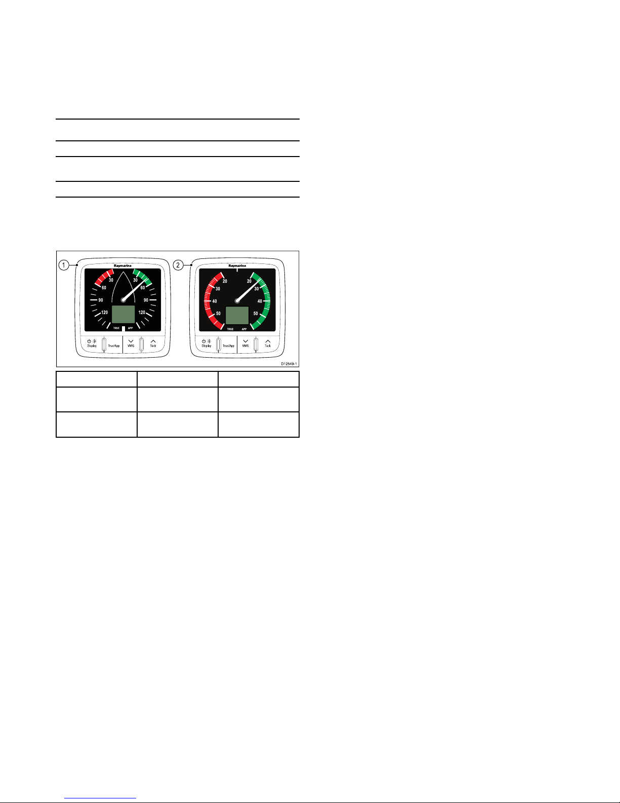
i60instrumentrange
Raymarine'si60instrumentrangeconsistsofthefollowing
variants:
TackTrue/AppDisplay VMG TackTrue/AppDisplay VMG
1 2
D12549-1
ItemDescriptionPartnumber
1i60Analoguewind
instrument
E70061
2i60Analogueclose
hauledwindinstrument
E70062
i60Wind
Thei60Windinstrumentprovidesa360ºwinddirectionscale
andcanbeusedasastandaloneunitoraspartofaSeaTalkor
SeaTalk
ng
network.
i60Closehauledwind
Thei60Closehauledwindinstrumentprovidesanexpanded
indicationfrom20ºto+60ºaboutthebowandsternofthe
vessel.Thei60Closehauledwindmustbeusedaspartofa
SeaTalkorSeaT alk
ng
network.
10i60
Page 11

Chapter3:Planningtheinstallation
Chaptercontents
•3.1Installationchecklistonpage12
•3.2Systemintegrationonpage13
•3.3Typicalsystemsonpage14
•3.4Systemprotocolsonpage16
•3.5Partssuppliedonpage16
•3.6T oolsrequiredonpage17
Planningtheinstallation
11
Page 12

3.1Installationchecklist
Installationincludesthefollowingactivities:
InstallationTask
1Planyoursystem.
2
Obtainallrequiredequipmentandtools.
3
Siteallequipment.
4Routeallcables.
5
Drillcableandmountingholes.
6Makeallconnectionsintoequipment.
7
Secureallequipmentinplace.
8Poweronandtestthesystem.
12
i60
Page 13
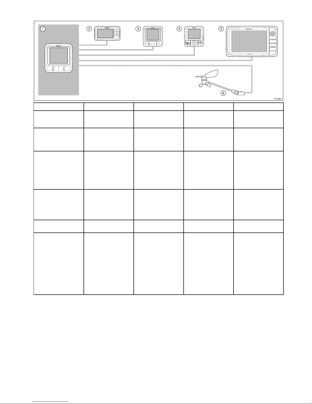
3.2Systemintegration
2 3
6
4
5
1
D1239 5-1
ItemDevicetypeMaximumQuantitySuitableDevicesConnections
1
i60Wind,Closehauledwind
instrument.
Asdeterminedbythe
SeaTalk
ng
busbandwidth
andpowerloading.
•i60Wind
•i60Closehauledwind
•SeaTalk
ng
2
SeaTalkinstrumentdisplays.
Asdeterminedbythe
SeaTalkbusbandwidthand
powerloading.
•i40
•ST40
•ST60+
•SeaTalk
ng
viatheoptional
SeaTalk1toSeaT alk
ng
converter
3
SeaTalk
ng
Instrument
displays.
Asdeterminedbythe
SeaTalk
ng
busbandwidth
andpowerloading.
•i50
•i60
•i70
•ST70
•ST70+
•SeaTalk
ng
4
SeaTalk
ng
pilotcontroller.
Asdeterminedbythe
SeaTalk
ng
busbandwidth
andpowerloading.
•ST70
•ST70+
•p70
•p70R
•SeaTalk
ng
5
SeaTalk
ng
Multifunction
displays.
6
•Raymarinemultifunction
displays.
•SeaTalk
ng
6RaymarineWindtransducers
androtavecta.
•1xwindvanetransducer,
or
•1xrotavectawind
transducer.
•Shortarmwindvane
transducer.
•Longarmwindvane
transducer.
•Shortarmmastheadwind
transducer.
•Longarmmastheadwind
transducer.
•Rotavectawind
transducer.
Raymarinetransducer
connections.
Planningtheinstallation
13
Page 14
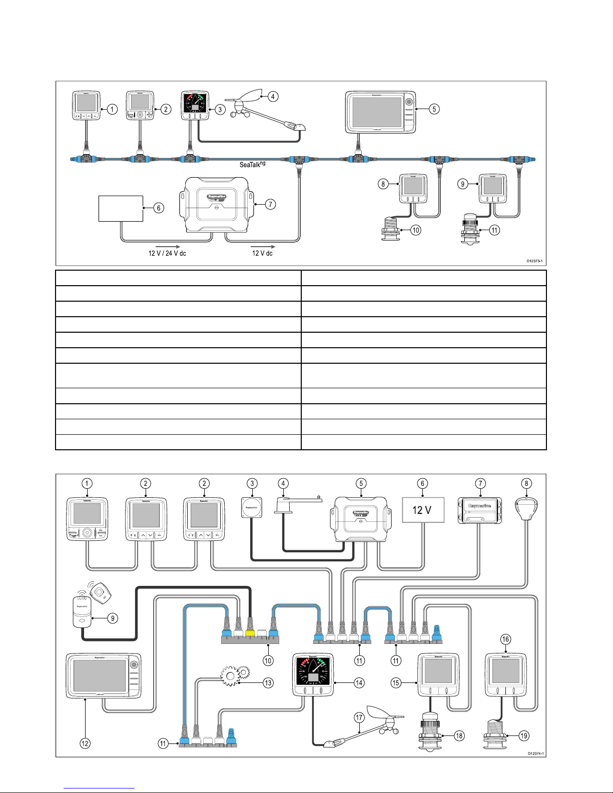
3.3T ypicalsystems
TheinstrumentrangecanbeconnecteddirectlytoaSeaT alk
ng
network.Theinstrumentrangecanalsobeconnectedtoa
SeaTalksystemusingtheSeaTalktoSeaT alk
ng
adaptorcable.
BasicSeaT alk
ng
systemexample
S
S
M
M
A
A
R
R
T
T
P
P
I
I
L
L
O
O
T
T
D1237 3-1
12 V / 24 V dc
12 V dc
SeaTalk
ng
1 2
6
10 11
8 9
5
7
3
4
1
SeaTalk
ng
instrumentdisplay
2
SeaTalk
ng
pilotcontroller
3i60Windinstrument
4Raymarinewindvanetransducer
5
Raymarinemultifunctiondisplay
6
12/24Vdcpowersupply
7
Raymarinecoursecomputer(providing12VdcpowersupplytotheSeaT alk
ng
network.)
8
i50Speedinstrument
9i50Depthinstrument
10
Speedtransducer
11Depthtransducer
ExtendedSeaT alk
ng
systemexample
S
S
M
M
A
A
R
R
T
T
P
P
I
I
L
L
O
O
T
T
12 V
D1237 4-1
10
12
11 11
1 2 2 3 4 5
17
6 7 8
16
9
11
1514
13
18 19
14
i60
Page 15

1
SeaTalk
ng
pilotcontroller
2
SeaTalk
ng
instrumentdisplays
3Fluxgatecompass
4
Rudderreference
5
Raymarinecoursecomputer(providing12VdcpowersupplytoSeaTalk
ng
network.)
6
12/24Vdcpowersupply
7
RaymarineAIStransceiver
8
RaymarineSeaTalk
ng
GPS
9Manoverboard
10
SeaTalktoSeaT alk
ng
converter
11
SeaTalk
ng
5wayblocks
12
Raymarinemultifunctiondisplay
13
Enginedata(viadevicenetadaptorcable.)
14i60Windinstrument
15i50Depthinstrument
16
i50Speedinstrument
17Raymarinewindvanetransducer
18Depthtransducer
19
Speedtransducer
Planningtheinstallation
15
Page 16
3.4Systemprotocols
Yourproductcanbeconnectedtovariousproductsandsystems
toshareinformationandsoimprovethefunctionalityofthe
overallsystem.Theseconnectionsmaybemadeusinga
numberofdifferentprotocols.Fastandaccuratedatacollection
andtransferisachievedbyusingacombinationofthefollowing
dataprotocols:
•SeaT alk
ng
•NMEA2000
•SeaT alk
Note:Youmayndthatyoursystemdoesnotuseallofthe
connectiontypesorinstrumentationdescribedinthissection.
Seatalk
ng
SeaTalk
ng
(NextGeneration)isanenhancedprotocolfor
connectionofcompatiblemarineinstrumentsandequipment.It
replacestheolderSeaT alkandSeaT alk
2
protocols.
SeaTalk
ng
utilizesasinglebackbonetowhichcompatible
instrumentsconnectusingaspur.Dataandpowerarecarried
withinthebackbone.Devicesthathavealowdrawcanbe
poweredfromthenetwork,althoughhighcurrentequipmentwill
needtohaveaseparatepowerconnection.
SeaTalk
ng
isaproprietaryextensiontoNMEA2000andthe
provenCANbustechnology .CompatibleNMEA2000and
SeaTalk/SeaT alk
2
devicescanalsobeconnectedusingthe
appropriateinterfacesoradaptorcablesasrequired.
NMEA2000
NMEA2000offerssignicantimprovementsoverNMEA0183,
mostnotablyinspeedandconnectivity .Upto50unitscan
simultaneouslytransmitandreceiveonasinglephysicalbusat
anyonetime,witheachnodebeingphysicallyaddressable.The
standardwasspecicallyintendedtoallowforawholenetwork
ofmarineelectronicsfromanymanufacturertocommunicateon
acommonbusviastandardizedmessagetypesandformats.
SeaTalk
SeaTalkisaprotocolwhichenablescompatibleinstrumentsto
connecttoeachotherandsharedata.
TheSeaT alkcablesystemisusedtoconnectcompatible
instrumentsandequipment.Thecablecarriespoweranddata
andenablesconnectionwithouttheneedforacentralprocessor.
AdditionalinstrumentsandfunctionscanbeaddedtoaSeaTalk
system,simplybypluggingthemintothenetwork.SeaT alk
equipmentcanalsocommunicatewithothernon-SeaT alk
equipmentviatheNMEA0183standard,providedasuitable
interfaceisused.
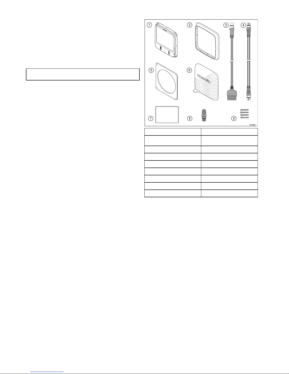
3.5Partssupplied
D1238 8-1
1 2
5 6
98
43
7
1i60instrument
2Frontbezel
3
SeaTalktoSeaTalk
ng
adaptorcable
4
SeaTalk
ng
spurcable
5
Gasket
6
Suncover
7
Documentationpack
8
SeaTalk
ng
blankingplug
9
4xxingscrews
16i60
Page 17

3.6Toolsrequired
Toolsrequiredforinstallation
D1253 0-1
3
4
2
1
5
1Pozi-drivescrewdriver
2File
3
92mm(3.62in)holecutter
4Adhesivetape
5
Powerdrill
Planningtheinstallation
17
Page 18

18i60
Page 19

Chapter4:Cablesandconnections
Chaptercontents
•4.1Generalcablingguidanceonpage20
•4.2Connectionsoverviewonpage20
Cablesandconnections19
Page 20

4.1Generalcablingguidance
Cabletypesandlength
Itisimportanttousecablesoftheappropriatetypeandlength
•Unlessotherwisestateduseonlystandardcablesofthe
correcttype,suppliedbyRaymarine.
•Ensurethatanynon-Raymarinecablesareofthecorrect
qualityandgauge.Forexample,longerpowercablerunsmay
requirelargerwiregaugestominimizevoltagedropalongthe
run.
Routingcables
Cablesmustberoutedcorrectly,tomaximizeperformanceand
prolongcablelife.
•DoNOTbendcablesexcessively .Whereverpossible,ensure
aminimumbenddiameterof200mm(8in)/minimumbend
radiusof100mm(4in).
100 mm (4 in)
200 mm (8 in)
•Protectallcablesfromphysicaldamageandexposuretoheat.
Usetrunkingorconduitwherepossible.DoNOTruncables
throughbilgesordoorways,orclosetomovingorhotobjects.
•Securecablesinplaceusingtie-wrapsorlacingtwine.Coil
anyextracableandtieitoutoftheway .
•Whereacablepassesthroughanexposedbulkheador
deckhead,useasuitablewatertightfeed-through.
•DoNOTruncablesneartoenginesoruorescentlights.
Alwaysroutedatacablesasfarawayaspossiblefrom:
•otherequipmentandcables,
•highcurrentcarryingacanddcpowerlines,
•antennae.
Strainrelief
Ensureadequatestrainreliefisprovided.Protectconnectors
fromstrainandensuretheywillnotpulloutunderextremesea
conditions.
Cableshielding
Ensurethatalldatacablesareproperlyshieldedthatthe
cableshieldingisintact(e.g.hasn’tbeenscrapedoffbybeing
squeezedthroughatightarea).
4.2Connectionsoverview
ConnectionsaremadeusingtheprovidedSeaT alk
ng
and
transducercableconnectorsontherearoftheunit.
SeaTalk
ng
connections
Theunithas2xSeaT alk
ng
connectorsontherearforconnecting
toaSeaT alk
ng
network.
D1205 6-1
ConnectingSeaT alk
ng
cables
1.Rotatethelockingcollaronthebackoftheunittothe
UNLOCKEDposition.
2.Ensurethespurcableendconnectoriscorrectlyoriented.
3.Fullyinsertthecableconnector .
4.Rotatelockingcollarclockwise(2clicks)untilitsnapsinto
theLOCKEDposition.
Transducerconnections
Transducerconnectionsonlyapplytothei60Windinstrument,
thei60Closehauledwinddoesnotincludetransducer
connectionsasitisarepeaterdisplay.
i60transducerconnections
6
7
3
4
5
D1239 6-1
1
2
1Blue
Rotor+(Rotavecta)
2Red
Rotor–(Rotavecta)
3
GreyWind0V(Shield)
4Yellow
Anemometer(signal)
5
Blue
Cosinewinddirection
6
GreenSinewinddirection
7
RedWindV+
20i60
Page 21

Note:Connectors1and2arerotavectaconnections,
connectors3to7areforwindtransducers.
Makingtransducerconnections
Althoughthetransducercableisttedwithspadeconnectorsfor
directconnectiontotherearoftheunit,itmaybenecessaryto
removethesetofacilitateinstallation,e.g.ifthecablehastobe
routedthroughnarrowapertures.1/8thspadeterminalswillbe
required(notsupplied),toreplacethoseremoved.Whentting
thenewspadeconnectors,preparethecablesasdetailedbelow:
3 mm
6 mm
50 mm
1
2
D1235 9-1
1.Preparethecableasshownin1above.
2.Foldbackthewirestrandsandinsertintothenewspade
connectorasshownin2above.
3.Ensurethewirestrandsdonotextendbeyondtherearofthe
spadeconnectorinsulation.
4.Crimptheconnectortothewire.
iTC-5connection
TransducerscanbeconnectedtoaSeaT alk
ng
networkusing
Raymarine'sInstrumenttransducerconverter(iTC-5)andani70
instrument,thedatacanthenberepeatedonani50/i60unit.
12 V
D1203 3-3
1 2 3 4
5
6 7 8
1
i50Depth(Repeater)
2
i70Instrument(Master)
3
i50Speed(Repeater)
4
i60Wind(Repeater)
5
iTC-5
6Depthtransducer
7
Windvanetransducer
8
Speedtransducer
Note:TransducersconnectedtotheiTC-5mustbecalibrated
usingani70(master)unit.Transducersconnectedtothe
iTC-5cannotbecalibratedusingani50/i60.
MakingiTC-5transducerconnections
ForinstructionsonconnectingtransducerstoyouriTC-5refer
totheiTC-5handbook.
Powerconnection
PowerissuppliedtotheproductovertheSeaT alk
ng
network.
ASeaTalk
ng
systemrequiresone12Vdcsupply,connectedto
theSeaTalk
ng
backbone.Thiscanbeprovided:
•Byabatteryviathedistributionpanel,or
•FromaRaymarinecoursecomputer,viaaSeaT alkora
SeaTalk
ng
system.
Powerconnectionexample
SeaTalk
ng
powerconnection
SeaTalk
ng
D1239 1-1
12 V
3
1
2
1
SeaTalk
ng
instrument.
2
SeaTalk
ng
instrument.
312Vdcvesselpowersupply.
Warning:Groundingnotrequired
ThisproductisfullyinsulatedanddoesNOT
requireseparategrounding.
Warning:Positivegroundsystems
Donotconnectthisunittoasystemwhichhas
positivegrounding.
SeaTalkpowerprotection
Thepowersupplymustbeprotectedbya5Afuseoracircuit
breakerprovidingequivalentprotection.
Raymarinerecommendsthatthepowerisconnectedtoa
SeaTalksysteminsuchawaythatthecurrentdrawnoneach
sideofthepowerconnectionpointisequal.
SeaTalkpowercables
PartnumberDescription
D229
SeaTalkpowercable.
SeaTalk
ng
powerprotection
Thepowersupplymustbeprotectedbya5Afuseoracircuit
breakerprovidingequivalentprotection.
Raymarinerecommendsthatthepowerisconnectedtoa
SeaTalk
ng
systeminsuchawaythatthecurrentdrawnoneach
sideofthepowerconnectionpointisequal.
SeaTalk
ng
powercables
PartnumberDescription
A06049
SeaTalk
ng
powercable
Cablesandconnections
21
Page 22

SeaTalk
ng
connection
TheunitcanbeconnectedaspartofaSeaTalk
ng
network.
12 V dc
SeaTalk
ng
D1253 1-1
1 1 2 3
4
5 6
7 8
1
i70instrumentdisplays(SeaTalk
)ng
)
2
i60Windinstrument(SeaTalk
)ng
)
3Raymarinewindvanetransducer
412Vdcpowersupply
5
i50Speedinstrument(SeaTalk
)ng
)
6
i50Depthinstrument(SeaTalk
)ng
)
7
Speedtransducer
8Depthtransducer
SeaTalk
ng
cabling
SeaTalk
ng
cablesandconnectors
Connection/CableNotes
Backbonecables(variouslengths)Themaincablecarryingdata.Spurs
fromthebackboneareusedto
connectSeaT alk
ng
devices.
T-piececonnectorsUsedtomakejunctionsinthe
backbonetowhichdevicescanthen
beconnected.
Terminators
Requiredateitherendofthe
backbone.
Spurcables
Usedtoconnectdevices.Devices
maybedaisychainedorconnected
directlytotheT-pieces
SeaTalk
ng
5–wayconnector
Usedtobranch,split,ormake
additionalconnectionsinSeaTalk
ng
networks.
SeaTalk
ng
power
TheSeaTalk
ng
busrequiresa12Vpowersupply.Thismaybe
providedfrom:
•RaymarineSPXcoursecomputer,or
•Otherseparateregulated12Vsupply .
Note:SeaT alk
ng
doesNOTsupplypowertomultifunction
displaysandotherequipmentwithadedicatedpowersupply
input.
SeaTalkconnection
ConnectionstoanexistingSeaT alksystemmustbemadeusing
aSeaT alktoSeaT alk
ng
adaptorcable.
BasicSeaT alksystemexample
12 V dc
12 / 24 V dc
D1205 8-2
98
11 12
4
1 2 3
7
5
6 6 7
10
1
i70Instrumentdisplay(SeaTalk
ng
)
2
i50Speedinstrument(SeaTalk
ng
)
3
i50Depthinstrument(SeaTalk
ng
)
4Raymarinewindvanetransducer
5
i60Windinstrument(SeaTalk
ng
)
6
SeaTalk
ng
cables
7
SeaTalktoSeaTalk
ng
adaptorcables
8
Speedtransducer
9Depthtransducer
10
12/24Vdcpowersupply
11
SeaTalkCoursecomputer(providing
12VdcpowertoSeaT alknetwork.)
12
ST6002pilotcontroller(SeaTalk)
SeaTalkaccessories
SeaTalkcablesandaccessoriesforusewithcompatible
products.
DescriptionPartNoNotes
3–waySeaTalk
junctionbox
D244
1m(3.28ft)SeaTalk
extensioncable
D284
3m(9.8ft)SeaT alk
extensioncable
D285
5m(16.4ft)SeaTalk
extensioncable
D286
9m(29.5ft)SeaTalk
extensioncable
D287
12m(39.4ft)SeaT alk
extensioncable
E25051
20m(65.6ft)SeaT alk
extensioncable
D288
NMEA2000connection
Youcaneither:
22
i60
Page 23

•UseyourSeaTalk
ng
backboneandconnecteachNMEA2000
deviceonaspur ,OR
•connecttheinstrumentdisplayonaspurintoanexisting
NMEA2000backbone.
Important:Y oucannothaveany2terminatedbackbones
connectedtogether ,unlessyouhaveanisolationgateway
betweenthetwobackbones.
ConnectingNMEA2000equipmenttotheSeaTalk
ng
backbone
12V NMEA 2000
SeaTalk
ng
D1238 0-1
3
1
2
4
1.12Vdcpowersupplyintobackbone.
2.SeaTalk
ng
backbone.
3.SeaTalk
ng
toDeviceNetadaptorcable.
4.NMEA2000equipment.
ConnectingtheunittoanexistingNMEA2000(DeviceNet)
backbone
D1237 7-1
1
4
2
3
1.SeaTalk
ng
instrumentdisplay
2.SeaTalk
ng
toDeviceNetadaptorcable.
3.DeviceNetbackbone.
4.NMEA2000equipment.
Cablesandconnections23
Page 24

24
i60
Page 25

Chapter5:Locationandmounting
Chaptercontents
•5.1Selectingadisplaylocationonpage26
•5.2Mountingonpage27
•5.3Frontbezelonpage27
•5.4Selectingatransducerlocationonpage28
Locationandmounting
25
Page 26

5.1Selectingadisplaylocation
Warning:Potentialignitionsource
ThisproductisNOTapprovedforusein
hazardous/ammableatmospheres.DoNOTinstall
inahazardous/ammableatmosphere(suchasin
anengineroomornearfueltanks).
Generallocationrequirements
Whenselectingalocationfortheunititisimportanttoconsidera
numberoffactors.
Ventilationrequirements
Toprovideadequateairow:
•Ensurethatequipmentismountedinacompartmentof
suitablesize.
•Ensurethatventilationholesarenotobstructed.
•Ensureadequateseparationofequipment.
Mountingsurfacerequirements
Ensureunitsareadequatelysupportedonasecuresurface.Do
NOTmountunitsorcutholesinplaceswhichmaydamagethe
structureofthevessel.
Cableroutingrequirements
Ensuretheunitismountedinalocationwhichallowsproper
routingandconnectionofcables:
•Minimumcablebendradiusof100mm(3.94in)isrequired
unlessotherwisestated.
•Usecablesupportstopreventstressonconnectors.
Wateringress
Thisunitissuitableformountingbothaboveandbelowdecks.It
iswaterprooftoIPX6standard.Althoughtheunitiswaterproof,
itisgoodpracticetolocateitinaprotectedareaawayfrom
prolongedanddirectexposuretorainandsaltspray .
Electricalinterference
Selectalocationthatisfarenoughawayfromdevicesthat
maycauseinterference,suchasmotors,generatorsandradio
transmitters/receivers.
Magneticcompass
Whenchoosingasuitablelocationyoushouldaimtomaintain
themaximumpossibledistancebetweentheunitandany
compasses.
Topreventpotentialinterferencewiththevessel'smagnetic
compasses,ensurethataminimumdistanceof230mm(9in)
betweentheunitandanyinstalledcompassesismaintained.
Viewingangleconsiderations
Asdisplaycontrast,colorandnightmodeperformanceareall
affectedbytheviewingangle,Raymarinerecommendsyou
temporarilypowerupthedisplaywhenplanningtheinstallation,
toenableyoutobestjudgewhichlocationgivestheoptimum
viewingangle.
Viewingangle
Dxxxxx-1
70°
70°
70°
70°
Productdimensions
D1238 9-1
A C G
D E
B
F
A
110mm(4.22”)
B
115mm(4.52”)
C14mm(0.55”)
D
30mm(1.18”)
E
35mm(1.38”)
F
90mm(3.54”)
G17mm(0.67”)
26i60
Page 27

5.2Mounting
Pre-mountingcheck
Theproductisdesignedtobesurfacemounted.Before
mountingtheunit,ensureyouhave:
•Selectedasuitablelocation.
•Identiedthecableconnectionsandroutethatthecableswill
take.
•Detachedthefrontbezel.
•Removethekeypadmat.
Mountingdiagram
D1237 9-1
Mountinginstructions
1.Checktheselectedlocationfortheunit,aclear,atareawith
suitableclearancebehindthepanelisrequired.
2.Fixthemountingtemplatesuppliedwiththeproduct,tothe
selectedlocation,usingmaskingorselfadhesivetape.
3.Ifpossibleuseanappropriatesizeholecuttingsawandcut
outthecentreholecutoutareaasindicatedonthemounting
template,or
4.Usingasuitableholecuttingsaw ,makepilotholesineach
cornerofthecutoutareaandusingajigsawcutalongthe
insideedgeofthecutoutline.
5.Ensurethattheunittsintotheremovedareaandthenle
aroundthecutedgeuntilsmooth.
6.Drillanyrequiredholesasindicatedonthemounting
templateforthesecuringscrews.
7.Connecttherelevantcablestotheunit.
8.Peelthebackingoffofthesuppliedgasketandplacethe
adhesivesideofthegasketontothedisplayunitandpress
rmlyontotheange.
9.Slidetheunitintoplaceandsecureusingthescrews
provided.
10.Retkeypadmatandfrontbezel.
Note:Drill,tapsizeandtighteningtorquesaredependant
uponthematerialtypeandthicknessofthemountingsurface.
Note:Thesuppliedgasketprovidesasealbetweentheunit
andasuitablyatandstiffmountingsurfaceorbinnacle.
Thegasketshouldbeusedinallinstallations.Itmayalso
benecessarytouseamarine-gradesealantifthemounting
surfaceorbinnacleisnotentirelyatandstifforhasarough
surfacenish.
5.3Frontbezel
Removingthefrontbezel
D1237 2-1
1 2
3 4
Note:Usecarewhenremovingthebezel.Donotuseany
toolstoleverthebezel,doingsomaycausedamage.
1.Usingyourngerspullthebezelawayfromtheunitatthe
topandside,asshownin2.
Thebezelwillstarttocomeawayfromtheunitatthetop
andside.
2.Nowpullthebezelawayfromtheunitontheoppositeside,
asshownin3.
Thebezelwillnowcomefreefromtheunit,asshownin4.
Locationandmounting
27
Page 28

5.4Selectingatransducerlocation
Windvanetransducer/rotavectalocation
requirements
Whenselectingalocationforyourwindtransduceritisimportant
toconsideranumberoffactors.
Thetransducer'slocationmust:
•Allowreasonableaccessforinstallationandservicing.
•Beashighaspossibleandawayfromanyequipmentwhich
mayshieldthetransducerorotherwisedisturbtheairow.
•Provideahorizontalmountingsurface.Ifasurface(e.g.
masttop)isotherwisesuitablebutnothorizontal,makeup
asuitablewedgedpackingpiecetoprovidethenecessary
horizontalsurface.
•Theremustalsobeaviablerouteforthetransducercableto
beroutedtotheinstrumentdisplay .
Windvanetransducerandrotavecta
mounting
Ensurethatthewindtransducerorrotavectaisinstalledin
accordancewiththeinstructionssuppliedwiththeunit.
28i60
Page 29

Chapter6:Gettingstarted
Chaptercontents
•6.1Controlsonpage30
•6.2Poweronpage30
•6.3Datamasteronpage31
•6.4Illuminationonpage31
•6.5Calibrationonpage32
Gettingstarted
29
Page 30

6.1Controls
1
3
2
4
D1237 5-1
1
Display(Power)—Powerthe
instrumentdisplayonandoff,adjust
backlightandcontrastlevels.
2
True/App—Switchbetweentrue
andapparentwinddirection.
3
VMG—DisplayVelocitymade
good.
4Tack—T ackheading.
6.2Power
Poweringontheunit
Withpowertotheunitturnedonbuttheunitswitchedoff:
1.PressandholdthePowerbuttonuntiltheunitpowersonand
dataisdisplayed(approximately2seconds).
Note:Whenpowertotheunitisturnedontheunitwillswitch
onautomatically .
Poweringofftheunit
1.PressandholdthePowerbuttonuntilthepowercountdown
timerisdisplayedandreacheszero(approximately6to8
seconds).
Calibrationalert
IftheCALlegendonthedigitaldisplayashesfortherst
30secondsafterpowerup,refertotheCalibrationsectionto
calibrateyourunit.
30i60
Page 31

6.3Datamaster
Whereasystemcontainsmorethanoneunitcapableof
displayingadatatype,theunitphysicallyconnectedtothe
transducermustbesetasthedatamasterandanyotherunits
setasarepeater.
Settingaunitasdatamaster
1.RefertotheIntermediatecalibrationsectionfordetailson
howtosetyourunitasdatamaster.
6.4Illumination
Adjustingthebacklightlevel
Thebacklightingcanbeadjustedusingthepowerbutton.
Duringnormaloperation:
1.PressandholdthePowerbuttonforapproximately1second
todisplaythebacklightpage.
2.UsetheVMGorTackbuttonstoadjustthebacklighttothe
requiredlevel.
Note:Thebacklightpagewilltime-outafter8secondsof
inactivity.
Gettingstarted
31
Page 32

6.5Calibration
Beforerstusecalibrationproceduresmustbecarriedoutto
ensureoptimumperformanceoftheinstrumentwiththevessel.
Thecalibrationproceduresare:
•Usercalibration
•Intermediatecalibration
•Groupsetup
•Dealercalibration
Note:Groupsetupisforgroupilluminationandisnotpartof
thecalibrationprocess.
Usercalibration
Thei60Closehauledwindisarepeatdisplayandassuchdoes
notrequirecalibration,thestepsbelowapplytothecalibrationof
thei60Windinstrumentonly .
Usercalibrationoptionsinclude:
•Windangleoffset
•Windspeedunits
Linearizingandaligningthewindtransducer
Youcanlinearizeandalignthewindtransducerbyfollowing
thestepsbelow.
Youwillneedtobeunderway,withsufcientspacetoturnina
largecircleunhindered.
1.Slowlyturnthevesselthrough2completecircles.
x 2
D1241 5-1
Thisprocedureautomaticallylinearizesthewindvane.A
successfullinearizationisindicatedbythedigitaldisplay
ashingandabuzzersoundingthreebeeps.
2.PressandholdthePowerandTrue/Appbutton
simultaneouslyforapproximately2secondstoentertheuser
calibrationmenu.
True
App
+
D1248 8-1
10
15
20
25
30
35
40
45
50
55
60
5
2
3.PressthePowerbuttontodisplaythewindangleoffsetpage.
D1248 9-1
4.Sailyourvesseldirectlyintothewindandadjusttheanalog
pointerto0,usingtheVMGandT ackbuttons.
D1249 0-1
Tack
VMG
TheVMGbuttonwilldecreasethecurrentvalueandthe
Tackbuttonwillincreasethecurrentvalue.Asyoudothis,
thewindangleoffsetshowstheamountofcorrectionyou
haveapplied.
5.Toexittheusercalibrationpagesatanytimepressand
holdthePowerandTrue/Appbuttonssimultaneouslyfor
approximately2seconds.
Selectingwindspeedunits
Windspeedunitscanbedisplayedineitherknotsormetersper
second.Tochangethewindspeedunitsfollowthestepsbelow .
Fromtheusercalibrationpages:
1.PressthePowerbuttontodisplaythewindspeedunits
page,or
D1249 1-1
2.UsetheVMGandTackbuttonstoselecttherequiredwind
units.
3.Toexittheusercalibrationpagesatanytimepressand
holdthePowerandTrue/Appbuttonssimultaneouslyfor
approximately2seconds.
Intermediatecalibration
Intermediatecalibrationallowsyouto:
i60Windi60Closehauledwind
Checkinstrumentsoftwareversion.Checkinstrumentsoftwareversion.
Checktheinstrumentstatus(either
masterorrepeater).
10
15
20
25
30
35
40
45
50
55
60
5
4
+
D1249 2-1
CAL
True
App
Checkingthesoftwareversion
Youcancheckthesoftwareversionoftheunitbyfollowingthe
stepsbelow.
Duringnormaloperation:
1.PressandholdthePowerandTrue/Appbuttons
simultaneouslyforapproximately4seconds.
Thecurrentsoftwareversionisdisplayed.Thesoftware
versionpagewilltime-outautomaticallyafter8secondsof
inactivity.
2.PressthePowerbuttontodisplaytheinstrumentstatus.
Checkingtheinstrumentstatus
Youcanchecktheinstrumentdisplay'sstatusbyfollowingthe
stepsbelow.
Fromthesoftwareversionpage:
1.PressthePowerbutton.
Theinstrumentstatusisdisplayed(r0=masterandr1
=repeater).Theinstrumentstatuspagewilltime-out
automaticallyafter8secondsofinactivity.
Dealercalibration
Thedealercalibrationproceduresinclude:
•SettingUsercalibrationoptionsonoroff.
•Settingrequiredwindangleandspeedresponse.
•Settingthevelocitymadegood(VMG)response.
•Settingboatshowmodeonoroff.
•Restorefactorydefault
Settingdealercalibrationoptions
Tosetthedealercalibrationoptionsfollowthestepsbelow:
Duringnormaloperation:
1.PressandholdthePowerandTrue/Appbuttonsfor
approximately14secondstodisplaythedealercalentry
page.
10
15
20
25
30
35
40
45
50
55
60
5
14
+
D1249 3-1
True
App
CAL
2.PresstheVMGandTackbuttonssimultaneouslytodisplay
theusercalibrationaccesspage.
+
D1249 4-1
Tack
VMG
CAL
CAL
32i60
Page 33

3.UsetheVMGorT ackbuttonstoturnusercalibrationonand
off.
4.PressthePowerbuttontodisplaythewindangleresponse
page.
D1249 5-1
CAL
5.UsetheVMGorT ackbuttonstosettherequiredwindangle
responsevalues.
6.PressthePowerbuttontodisplaythewindspeedresponse
page.
D1249 6-1
CAL
7.UsetheVMGorT ackbuttonstosettherequiredwindspeed
responsevalues.
8.PressthePowerbuttontodisplaytheVMGresponsepage.
D1249 7-1
CAL
VMG
9.UsetheVMGorTackbuttonstosettherequiredVMG
responsevalues.
10.PressthePowerbuttontodisplaythewindspeedpage.
D1249 8-1
CAL
KTS
11.PresstheVMGorTackbuttonstodisplaythewindspeed
calibrationpage.
D1249 9-1
CAL
Tack
VMG
+
12.UsetheVMGorTackbuttonstoadjustthewindspeed
calibrationvalueto0.7.
13.PressthePowerbuttontodisplaytheboatshowmodepage.
D1250 0-1
CAL
14.UsetheVMGorT ackbuttonstoswitchboatshowmode
onandoff.
15.PressthePowerbuttontodisplaythefactoryresetpage.
D1250 1-1
CAL
16.UsetheVMGorTackbuttonstoresetunit'ssettingsto
factorydefaultvalues.
17.UsetheVMGorTackbuttonstoadjustthecurrentvalues
oneachpage.
18.T oexitthedealercalibrationpagesatanytimepressand
holdthePowerandTrue/Appbuttonssimultaneouslyfor
approximately2seconds.
Note:Usercalibrationaccess,windspeedandboatshow
modepagesarenotavailableonthei60Closehauledwind.
Gettingstarted
33
Page 34

34i60
Page 35

Chapter7:Usingyourdisplay
Chaptercontents
•7.1Pagesonpage36
•7.2i60Windoperationonpage36
•7.3Groupilluminationonpage37
Usingyourdisplay
35
Page 36

7.1Pages
Thepagesavailabledependonthedisplayvariantandare
showninthetablebelow:
i60Windi60Closehauledwind
WindspeedWindspeed
*Beaufortwindspeed*Maximumwindspeed
*MaximumwindspeedVMG
*Maximumtruewindspeedalarm
Tack
*Lowtruewindspeedalarm
*Highapparentwindanglealarm
*Lowapparentwindanglealarm
VMG
Tack
Note:*Thesepagesaretemporarypagesandwilltime-outto
thepreviouspermanentpageafter8secondsofinactivity.
Changingpages
Duringnormaloperation:
1.PresseitherthePowerbuttontocyclethroughthepages.
2.PresstheVMGbuttontodisplayVMGinformation.
3.PresstheT ackbuttontodisplaytackinformation.
7.2i60Windoperation
Whenconnectedtoarelevantrotavectaorwindvanetransducer
thei60provides:
•Trueandapparentwinddirectionandspeed.Windspeedis
displayedeitherinknots,meterspersecondorasBeaufort
scalevalues.
•Velocitymadegood(VMG)information,whenvesselspeed
informationisavailableonthenetwork.
•T ackangle,whenheadinginformationisavailableonthe
network.
•Maximumwindspeed.
•Highandlowtruewindspeedalarms.
•Highandlowapparentwindanglealarms.
Note:Alarmsareonlyavailableonthei60Windinstrument,
whensetasamasterunit.Noalarmsareavailableonthei60
Closehauledwindinstrument.
i60displayinformation
Thei60instrument'sdisplayconsistsofananaloguepointer
anddigitaldisplay.
Analoguedisplay
Theanaloguedisplaypointershowseithertrueorapparentwind
direction(Dependingonsetting).
Digitaldisplay
ThedigitaldisplayLCDshowsthefollowingwindinformation.
•Beaufortwindspeed
•True/apparentwindspeed
•Velocitymadegood(VMG)
•T ackheading
•Maximumwindspeed
•Windalarmdata
Usingthedisplay(Power)button
HI
LO
disp
KTS
KTSKTS
LO
KTS
KTS
Display
Display
DisplayDisplay
Display
Display
Display
Tack
10
15
20
25
30
35
40
45
50
55
60
5
3
D1255 2-1
Duringnormaloperation:
1.UsetheDisplaybuttontocyclethroughtheavailablepages.
2.PressandholdtheTackbuttonsfor3secondstoresetthe
maximumwindspeedtothecurrentwindspeed.
Note:AllpagesexceptfortheCurrentwindspeedpageare
temporaryandwilltime-outafter8seconds.
36i60
Page 37

UsingTackandVMGbuttons
TackTrue/ AppDisplay VMG
TACK
VMG
KTS
1
2
D1255 0-1
Duringnormaloperation:
1.PresstheVMGbuttontoshowtheVMGpageonthedigital
display.
Note:VMGinformationisonlyavailablewhenvesselspeed
informationisavailable.
2.PresstheT ackbuttontoshowtheT ackpageonthedigital
display.
Note:Tackinformationisonlyavailablewhenvesselheading
andspeedinformationisavailable.
Switchingbetweentrueandapparentwind
information
YoucanswitchtheunitbetweendisplayingTrueorApparent
windinformation.
D1255 1-1
1
2
Duringnormaloperation:
1.PresstheTrue/Appbuttontoswitchbetweentrueor
apparentwindinformation.
•InTruemodetheindicatorshownin1abovewillbe
displayed.
•InApparentmodetheindicatorshownin2abovewillbe
displayed.
7.3Groupillumination
Groupilluminationisusedtosynchronizesandcontrolthe
backlightinglevelofmultipleunitsassignedtothesamegroup.
TheunitcanparticipateinsharedilluminationviaaSeaT alk
networkorgroupilluminationviaaSeaTalk
ng
network.
WhenconnectedonaSeaT alknetworkallcompatibleunitswill
sharetheirbacklightlevel(when1unit'sbacklightinglevelis
adjustedallotherunitsbacklightlevelwillalsochange).
WhenconnectedonaSeaT alk
ng
networktheunitcanparticipate
ingroupilluminationandbeassignedtoagroupofunitswhich
willsharetheirbacklightinglevels.Availablegroupsareas
follows:
•Helm1
•Helm2
•Cockpit
•Flybridge
•Mast
•grP1togrP5
Whenassignedtoagroup,whenthebacklightingof1unitis
adjustedthebacklightinglevelofallunitsassignedtothesame
groupwillalsochange.
Assigningtheunittoagroup
Toassigntheunitaspartofagroupsothatitcanparticipatein
groupilluminationfollowthestepsbelow .
Duringnormaloperation:
1.PressandholdtheDisplay(Power)andTrue/appbuttons
simultaneouslyfor6seconds.
TheGroupbrightnessentrypageisdisplayed.
Note:TheGroupbrightnessentrypageisatemporary
pageandwilltime-outtothepreviouspageafter8seconds.
2.PresstheDisplay(Power)buttontodisplaytheGrouppage.
3.UsetheVMGorT ackbuttonstoselectthegrouptheunit
willbeassignedto.
Usingyourdisplay
37
Page 38

38i60
Page 39

Chapter8:Usingalarms
Chaptercontents
•8.1Alarmsonpage40
Usingalarms
39
Page 40

8.1Alarms
Alarmsalertyoutoasituationorhazardrequiringyourattention.
Youcansetupalarmstoalertyoutocertainconditions.
Alarmsareraisedbysystemfunctions,andalsoexternal
equipmentconnectedtoyourdisplay.
Whenanalarmeventoccursanaudibleandvisualalarmis
activatedwhichindicatesthealarmstate.
Alarmthresholdscanbeconguredfromtherelevantalarm
page/menu.
Instrumentalarms
Alarmsavailableonthei60Windarelistedbelow.
•Hightruewindspeed
•Lowtruewindspeed
•Highapparentwindangle
•Lowapparentwindangle
Note:Alarmsarenotavailableonthei60CloseHauledwind.
Alarmindications
Analarmeventisindicatedbybothaudibleandvisualwarnings.
Hightruewindspeedalarm
KTS
D1255 3-1
TheHightruewindspeedalarmsoundswhenthetruewind
speedisequaltoormorethantheHightruewindspeed
threshold.Thealarmsoundsuntilsilencedmanually.
Lowtruewindspeedalarm
D1255 4-1
KTS
LO
TheLowtruewindspeedalarmsoundswhenthetruewind
speedisequaltoorlessthantheLowtruewindspeed
threshold.Thealarmsoundsuntilsilencedmanually.
Highapparentwindanglealarm
D1255 5-1
HI
TheHighapparentwindanglealarmsoundswhenthe
apparentwindangleequaltoormorethantheHighapparent
windanglethreshold.Thealarmsoundsuntilsilenced
manually.
Lowapparentwindanglealarm
D1255 6-1
LO
TheLowapparentwindanglealarmsoundswhentheapparent
windangleisequaltoorlessthantheLowapparentwind
anglethreshold.Thealarmsoundsuntilsilencedmanually.
Silencingalarms
1.Pressanybuttontosilenceanactivealarm.
Enabling/Disablingalarms
Alarmscanbeenabledordisabledatanytime.
Withtherelevantalarmpagedisplayed:
1.PressandholdtheTackbuttonfor1secondtoswitchthe
alarmonoroff.
Whenthealarmisonthealarmthresholdisdisplayed.
Settingalarmthresholds
Youcanadjustthethresholdatwhichalarmsaretriggeredby
followingthestepsbelow.
D1255 7-1
+
-
+
KTS KTS
VMG
Tack
Tack
VMG
Withtherelevantalarmpagedisplayed:
1.PresstheVMGandT ackbuttonssimultaneouslytoenter
adjustmode.
Thecurrentthresholdwillstarttoash.
2.UsetheT ackbuttontoincreasethealarmthreshold.
3.UsetheVMGbuttontodecreasethealarmthreshold.
4.PresstheVMGandT ackbuttonssimultaneouslytosavethe
newalarmthresholdandexitadjustmode.
Note:Theillustrationaboveisanexampledepictingsetting
theMaximumtruewindspeedalarmthreshold.
40i60
Page 41

Chapter9:Maintainingyourdisplay
Chaptercontents
•9.1Serviceandmaintenanceonpage42
•9.2Condensationonpage42
•9.3Routineequipmentchecksonpage43
•9.4Cleaningonpage43
•9.5Cleaningthedisplaycaseonpage44
•9.6Cleaningthedisplayscreenonpage44
Maintainingyourdisplay
41
Page 42

9.1Serviceandmaintenance
Thisproductcontainsnouserserviceablecomponents.Please
referallmaintenanceandrepairtoauthorizedRaymarine
dealers.Unauthorizedrepairmayaffectyourwarranty.
9.2Condensation
Certainatmosphericconditionsmaycauseasmallamountof
condensationtoformontheunit'swindow.Thiswillnotdamage
theunitandwillclearaftertheunithasbeenswitchedonfora
shortperiod.
42
i60
Page 43

9.3Routineequipmentchecks
Raymarinestronglyrecommendsthatyoucompleteanumber
ofroutinecheckstoensurethecorrectandreliableoperation
ofyourequipment.
Completethefollowingchecksonaregularbasis:
•Examineallcablesforsignsofdamageorwearandtear.
•Checkthatallcablesaresecurelyconnected.
9.4Cleaning
Bestcleaningpractices.
Whencleaningthisproduct:
•DoNOTwipethedisplayscreenwithadrycloth,asthiscould
scratchthescreencoating.
•DoNOTuseabrasive,oracidorammoniabasedproducts.
•DoNOTuseajetwash.
Maintainingyourdisplay
43
Page 44

9.5Cleaningthedisplaycase
Thedisplayunitisasealedunitanddoesnotrequireregular
cleaning.Ifitisnecessarytocleantheunit,followthisbasic
procedure:
1.Switchoffthepowertothedisplay .
2.Wipethedisplaywithaclean,softcloth(amicrobreclothis
ideal).
3.Ifnecessary,useisopropylalcohol(IPA)oramilddetergent
toremovegreasemarks.
Note:DoNOTuseIPAoranyothersolventordetergenton
thescreenitself.
Note:Incertainconditions,condensationmayappearinside
thedisplayscreen.Thiswillnotharmtheunit,andcanbe
clearedbypoweringonthedisplayforashorttime.
9.6Cleaningthedisplayscreen
Acoatingisappliedtothedisplayscreen.Thismakesitwater
repellent,andpreventsglare.Toavoiddamagingthiscoating,
followthisprocedure:
1.Switchoffthepowertothedisplay .
2.Rinsethescreenwithfreshwatertoremovealldirtparticles
andsaltdeposits.
3.Allowthescreentodrynaturally.
4.Ifanysmearsremain,verygentlywipethescreenwitha
cleanmicrobrecleaningcloth(availablefromanopticians).
44
i60
Page 45

Chapter10:Troubleshooting
Chaptercontents
•10.1Troubleshootingonpage46
•10.2Instrumenttroubleshootingonpage47
•10.3Poweruptroubleshootingonpage48
•10.4Miscellaneoustroubleshootingonpage49
•10.5Self-testonpage50
Troubleshooting
45
Page 46

10.1Troubleshooting
Thetroubleshootinginformationprovidespossiblecausesand
correctiveactionrequiredforcommonproblemsassociatedwith
marineelectronicsinstallations.
AllRaymarineproductsare,priortopackingandshipping,
subjectedtocomprehensivetestandqualityassurance
programs.However,ifyouexperienceproblemswiththe
operationofyourproductthissectionwillhelpyoutodiagnose
andcorrectproblemsinordertorestorenormaloperation.
Ifafterreferringtothissectionyouarestillhavingproblems
withyourunit,pleasecontactRaymarineTechnicalSupportfor
furtheradvice.
46i60
Page 47

10.2Instrumenttroubleshooting
FaultCauseAction
Blankdisplay.Nopowersupply.
•Checkfuse/circuitbreaker.
•Checkpowersupply.
•CheckSeaTalk/SeaTalk
ng
cablingand
connectorsecurity.
SeaTalk/SeaT alk
ng
informationnotbeing
transferredbetweeninstruments.
SeaTalk/SeaTalk
ng
cablingorconnectorfault.•ChecksecurityofSeaT alk/SeaT alk
ng
connectionsbetweenunits.
•CheckconditionofSeaT alk/SeaTalk
ng
cables.
•Isolatefaultyunitbydisconnectingunitsone
byone.
AgroupofSeaTalk/SeaTalk
ng
unitsnotworking.SeaTalk/SeaTalk
ng
cablingorconnectorfault.•CheckthesecurityofSeaTalk/SeaTalk
ng
connectorsbetweenfunctioningand
non-functioningunits.
•ChecktheconditionofSeaT alk/SeaT alk
ng
cablebetweenfunctioningandnon-functioning
units.
Troubleshooting
47
Page 48

10.3Poweruptroubleshooting
Problemsatpowerupandtheirpossiblecausesandsolutionsaredescribedhere.
ProblemPossiblecausesPossiblesolutions
Checkrelevantfusesandbreakers.
Checkthatthepowersupplycableissoundandthatallconnections
aretightandfreefromcorrosion.
Thesystem(orpartofit)doesnotstart
up.
Powersupplyproblem.
Checkthatthepowersourceisofthecorrectvoltageandsufcient
current.
48i60
Page 49

10.4Miscellaneoustroubleshooting
Miscellaneousproblemsandtheirpossiblecausesandsolutionsaredescribedhere.
ProblemPossiblecausesPossiblesolutions
Checkrelevantfusesandbreakers.
Checkthatthepowersupplycableissoundandthatallconnections
aretightandfreefromcorrosion.
Intermittentproblemwithpowertothe
display.
Checkthatthepowersourceisofthecorrectvoltageandsufcient
current.
Softwaremismatchonsystem(upgrade
required).
Gotowww.raymarine.comandclickonsupportforthelatestsoftware
downloads.
Displaybehaveserratically:
•Frequentunexpectedresets.
•Systemcrashesorothererratic
behavior.
Corruptdata/otherunknownissue.Performafactoryreset.
Important:Thiswillresultinthelossofanysettingsanddata
(suchaswaypoints)storedontheproduct.Saveanyimportantdata
toamemorycardbeforeresetting.
Troubleshooting
49
Page 50

10.5Self-test
Theunithasabuiltinself-testtoaidfaultdiagnosis.The
resultingfailuresand/orfaultcodesshouldbeusedwhen
contactingRaymarinecustomersupport.
Startingself-test
Toaccesstheself-testmodefollowthestepsblow.
Duringnormaloperation:
1.PresstheDisplay(Power)andTackbuttonsimultaneously
for4seconds,untiltheunitbeeps.
2.WhentheunitbeepsimmediatelypresstheVMGandTack
buttonsimultaneously .
Self-teststage1willcommence.
3.AttheendofeachtestpresstheDisplay(Power)andTrue/
Appbuttonsimultaneouslytoprogresstothenextstage.
Self-teststages
Theself-testcomprisesofthefollowingstages
Self-teststage1
WhenenteringSelf-teststage1,theunitbeepsandthedisplay
showsStfollowedbyt1.
Self-teststage1willperformthefollowingtests:
•SeaT alk/SeaTalk
ng
self-test,whichchecksthereceiveand
transmitcircuits.
•EEPROMtest(readandwrite).
Ifthetestsaresatisfactory,Pisshownonthedisplay.
Ifthetestsarenotsatisfactory,thefollowingfailurecodesmay
begenerated:
Faultcode
F01
F02
Self-teststage2
WhenenteringSelf-teststage2,theunitbeepsandthedisplay
showst2,for1second.
Self-teststage2willperformthefollowingtests:
•Backlightingtest,whichcyclesbetweenonandoffevery
second.
•Anybuttonpresssoundsabeep.
•Displaytest,whichteststheLCDsegmentsinthefollowing
sequence,changingoncepersecond:
D4491-2
1 2 3
D4491-3
Whilethetestisprogressing,presseachofthedisplaybuttons
andcheckthatthebuzzersoundsaseachbuttonispressed.
Thetablebelowshowspossibleproblemsthatmaybe
encountered:
Failure
Noillumination.
Buttonilluminationfailure.
Degradeddialillumination
Nobeepwhenbuttonpressed.
LCDsegment(s)missingcompletely.
FaintLCDsegment(s).
Pointernotrotatingorerraticmovement
Self-teststage3
WhenenteringSelf-teststage3,theunitbeepsandthedisplay
showst3,for1second.
Self-teststage3willperformpointeroffsetandcorrections.
PressingtheDisplay(Power)buttonwillrotatethepointer
clockwisetoalignwiththemajorgraduations.
IfthepointerismisalignedusetheVMG(anti-clockwise)and
Tack(clockwise)buttonstomanuallyadjustthepointeroffset
untilcorrectalignmentisobtained.
Self-teststage4
AknowngoodtransducermustbeconnectedforSelf-teststage
4,andthevesselmustbeunderwayatsufcientspeedforthe
teststobeperformed.
WhenenteringSelf-teststage4,theunitbeepsandthedisplay
showst4,for1second.
Self-teststage4willperformatransducertest
IfthetestissatisfactorythenPisshownonthedisplay.
Ifthetestisnotsatisfactorythenafailcodewillbeshownon
thedisplay:
FaultcodeFailure
F5Rotavecta
F3Windvane
F4Annemometer
Toexitself-teststage4andsavepointeroffsetcorrections,press
theDisplay(Power)andT rue/Appbuttonssimultaneously
for2seconds.
Toexitself-teststage4withoutsavingpointeroffset
corrections,presstheDisplay(Power)andTrue/Appbuttons
simultaneously.
50i60
Page 51

Chapter11:Technicalsupport
Chaptercontents
•11.1Raymarinecustomersupportonpage52
•11.2Checkingthesoftwareversiononpage52
Technicalsupport
51
Page 52

11.1Raymarinecustomersupport
Raymarineprovidesacomprehensivecustomersupportservice.
YoucancontactcustomersupportthroughtheRaymarine
website,telephoneandemail.Ifyouareunabletoresolvea
problem,pleaseuseanyofthesefacilitiestoobtainadditional
help.
Websupport
Pleasevisitthecustomersupportareaofourwebsiteat:
www.raymarine.com
ThiscontainsFrequentlyAskedQuestions,servicinginformation,
e-mailaccesstotheRaymarineT echnicalSupportDepartment
anddetailsofworldwideRaymarineagents.
Telephoneandemailsupport
IntheUSA:
•Tel:+16033247900
•TollFree:+18005395539
•Email:Raymarine@custhelp.com
IntheUK,Europe,theMiddleEast,orFarEast:
•Tel:+44(0)1329246777
•Email:ukproduct.support@raymarine.com
Productinformation
Ifyouneedtorequestservice,pleasehavethefollowing
informationtohand:
•Productname.
•Productidentity .
•Serialnumber .
•Softwareapplicationversion.
Youcanobtainthisproductinformationusingthemenuswithin
yourproduct.
11.2Checkingthesoftwareversion
Followthestepsbelowtoidentifythesoftwareversionofyour
unit.
Duringnormaloperation:
1.PressandholdtheDisplay(Power)andTrue/Appbuttons
simultaneouslyfor4seconds.
Thesoftwareversionwillbedisplayedonthescreen.
52i60
Page 53

Chapter12:Technicalspecication
Chaptercontents
•12.1T echnicalspecicationonpage54
Technicalspecication
53
Page 54

12.1Technicalspecication
Nominalsupplyvoltage12Vdc
Operatingvoltagerange
10Vdcto16Vdc
Powerconsumption
•<1WTypical(Displayonly)
•2.4WMaximum(Transducerconnected)
Current•45to65mATypical(Displayonly)
•200mAMaximum(Transducerconnected)
LEN(RefertoSeaTalk
ng
referencemanualforfurtherinformation.)
4
Environmental
Operatingtemperature:–20ºCto+55ºC
Storagetemperature:–30ºCto+70ºC
Relativehumidity:93%
Waterproong:IPX6
Connections•2xSeaT alk
ng
connections(compliantwithSeaTalk)
•Transducerconnections
ConformanceEurope2004/108/EC
54i60
Page 55

Chapter13:Sparesandaccessories
Chaptercontents
•13.1Windtransducersonpage56
•13.2Sparesonpage56
•13.3SeaT alk
ng
cablesandaccessoriesonpage57
•13.4Convertersonpage58
Sparesandaccessories
55
Page 56

13.1Windtransducers
Thefollowingwindtransducersareavailableforthei60range:
DescriptionPartnumberNotes
WindvanetransducerE22078
RotavectatransducerZ195
Note:Othertransducersareavailablepleasecheckwithyour
localRaymarinedealer.
13.2Spares
Thetablebelowliststhesparepartsavailablefori60instrument
displays
DescriptionPartnumberNote
i50/i60/i70front
bezel
R22168
i50/i60/i70Suncover
R22169
i60KeypadR70133
56i60
Page 57

13.3SeaTalk
ng
cablesandaccessories
SeaTalk
ng
cablesandaccessoriesforusewithcompatible
products.
DescriptionPartNoNotes
BackboneKitA25062Includes:
•2x5m(16.4ft)
Backbonecable
•1x20m(65.6ft)
Backbonecable
•4xT-piece
•2xBackbone
terminator
•1xPowercable
SeaTalk
ng
0.4m(1.3ft)
spur
A06038
SeaTalk
ng
1m(3.3ft)
spur
A06039
SeaTalk
ng
3m(9.8ft)
spur
A06040
SeaTalk
ng
5m(16.4ft)
spur
A06041
SeaTalk
ng
0.4m(1.3ft)
backbone
A06033
SeaTalk
ng
1m(3.3ft)
backbone
A06034
SeaTalk
ng
3m(9.8ft)
backbone
A06035
SeaTalk
ng
5m(16.4ft)
backbone
A06036
SeaTalk
ng
9m(29.5ft)
backbone
A06068
SeaTalk
ng
20m(65.6ft)
backbone
A06037
SeaTalk
ng
tobareends
1m(3.3ft)spur
A06043
SeaTalk
ng
tobareends
3m(9.8ft)spur
A06044
SeaTalk
ng
Powercable
A06049
SeaTalk
ng
Terminator
A06031
SeaTalk
ng
T-piece
A06028Provides1xspur
connection
SeaTalk
ng
5–way
connector
A06064Provides3xspur
connections
SeaTalktoSeaTalk
ng
converter
E22158Allowstheconnection
ofSeaT alkdevicestoa
SeaTalk
ng
system.
SeaTalk
ng
Inline
terminator
A80001Providesdirect
connectionofaspur
cabletotheendofa
backbonecable.No
T-piecerequired.
SeaTalk
ng
Blanking
plug
A06032
SeaTalk(3pin)to
SeaTalk
ng
adaptor
cable0.4m(1.3ft)
A06047
SeaTalk2(5pin)to
SeaTalk
ng
adaptor
cable0.4m(1.3ft)
A06048
DescriptionPartNoNotes
DeviceNetadaptor
cable(Female)
A06045Allowstheconnection
ofNMEA2000devices
toaSeaTalk
ng
system.
DeviceNetadaptor
cable(Male)
A06046Allowstheconnection
ofNMEA2000devices
toaSeaTalk
ng
system.
DeviceNetadaptor
cable(Female)tobare
ends.
E05026Allowstheconnection
ofNMEA2000devices
toaSeaTalk
ng
system.
DeviceNetadaptor
cable(Male)tobare
ends.
E52027Allowstheconnection
ofNMEA2000devices
toaSeaTalk
ng
system.
Sparesandaccessories
57
Page 58

13.4Converters
PartnumberDescription
E22158
SeaTalktoSeaTalk
ng
Converter
58i60
Page 59

AppendixANMEA2000sentences
Thei60instrumentrangesupportsthefollowingNMEA2000ParameterGroupNumber(PGN)sentences.
PGnamePGNi60WindTransmiti60WindReceive
ISOAcknowledgement
59392
●
ISORequest
59904
●
ISOAddressclaim
60928
●●
ISOCommandedaddress
65240
●
NMEARequestgroupfunction
126208
●
NMEACommandgroupfunction
126208
●
NMEAAcknowledgegroupfunction
126208
●
PGNlist—TransmitPGN'sgroup
function
126464
●
PGNlist—ReceivedPGN's
groupfunction
126464
●
Productinformation
126996
●●
Heading/Tack
127237
●
Vesselheading127250
●
Magneticvariation127258
●
Speed
128259
●
COG&SOGrapidupdate
129026
●
GNSSPositiondata
129029
●
Winddata130306
●●
NMEA2000sentences59
Page 60

60i60
Page 61

Page 62

www.ra ym a rin e .c om
 Loading...