

Page 1

i50 Depth
i50 Speed
i50 T rida t a
Installation and operation
instructions
English
Date: 06-2014
Document number: 81341-2-EN
© 2014 Raymarine UK Limited
Page 2

Page 3

Trademarkandpatentsnotice
Autohelm,hsb
2
,RayTechNavigator,SailPilot,SeaTalk,SeaTalk
NG
,SeaTalk
HS
andSportpilotareregistered
trademarksofRaymarineUKLimited.RayTalk,Seahawk,Smartpilot,PathnderandRaymarineare
registeredtrademarksofRaymarineHoldingsLimited.
FLIRisaregisteredtrademarkofFLIRSystems,Inc.and/oritssubsidiaries.
Allothertrademarks,tradenames,orcompanynamesreferencedhereinareusedforidenticationonly
andarethepropertyoftheirrespectiveowners.
Thisproductisprotectedbypatents,designpatents,patentspending,ordesignpatentspending.
FairUseStatement
Youmayprintnomorethanthreecopiesofthismanualforyourownuse.Youmaynotmakeanyfurther
copiesordistributeorusethemanualinanyotherwayincludingwithoutlimitationexploitingthemanual
commerciallyorgivingorsellingcopiestothirdparties.
Softwareupdates
Checkthewebsitewww.raymarine.comforthelatestsoftwarereleasesforyourproduct.
Producthandbooks
ThelatestversionsofallEnglishandtranslatedhandbooksareavailabletodownloadinPDFformatfromthewebsite
www.raymarine.com.
Pleasecheckthewebsitetoensureyouhavethelatesthandbooks.
Copyright©2014RaymarineUKLtd.Allrightsreserved.
ENGLISH
Documentnumber:81341-2
Date:06-2014
Page 4

Page 5

Contents
Chapter1Importantinformation........................7
CertiedInstallation...................................................7
Wateringress............................................................7
Disclaimer.................................................................7
EMCinstallationguidelines........................................7
Suppressionferrites...................................................8
Connectionstootherequipment.................................8
Declarationofconformity............................................8
Productdisposal........................................................8
Warrantyregistration..................................................8
IMOandSOLAS........................................................8
Technicalaccuracy....................................................9
Chapter2Handbookinformation.......................11
2.1Documentinformation..........................................12
2.2Partssupplied......................................................13
2.3i50Productoverview............................................14
Chapter3Planningtheinstallation...................15
3.1Installationchecklist.............................................16
3.2Compatibletransducers........................................16
3.3Typicalsystems...................................................18
3.4Systemprotocols.................................................20
3.5T oolsrequired......................................................20
3.6Selectingadisplaylocation...................................21
3.7Productdimensions..............................................22
3.8Selectingatransducerlocation.............................22
Chapter4Cablesandconnections....................23
4.1Generalcablingguidance.....................................24
4.2Powerconnection................................................24
4.3SeaT alk
4.4Transducerconnections.......................................26
4.5iTC-5connection..................................................27
4.6SeaT alkconnection..............................................27
4.7NMEA2000connection.........................................28
ng
connections..........................................25
Chapter5Mounting.............................................29
5.1Mounting.............................................................30
5.2Frontbezel..........................................................31
6.12Illumination........................................................41
Chapter7i50Speed............................................43
7.1i50Speedoperation.............................................44
7.2i50Speedcontrols...............................................44
7.3Power.................................................................45
7.4Datamaster.........................................................45
7.5Calibration...........................................................46
7.6UserCalibration-i50Speed.................................46
7.7Intermediatecalibration—i50Speed....................49
7.8Dealercalibration—i50Speed.............................51
7.9Usingthespeedpages.........................................52
7.10Usingthelog,tripandtemperaturepages............53
7.11Usingthetimers.................................................53
7.12Illumination........................................................54
Chapter8i50Tridata...........................................55
8.1i50Tridataoperation............................................56
8.2i50Tridatacontrols...............................................56
8.3Power.................................................................57
8.4Datamaster.........................................................57
8.5Calibration...........................................................58
8.6UserCalibration-i50Tridata................................58
8.7Intermediatecalibration—i50Tridata...................62
8.8Dealercalibration—i50Tridata............................63
8.9UsingTridatadepthpages....................................65
8.10UsingTridataspeedpages.................................65
8.11UsingTridatatrip,log,tempandtimer
pages.......................................................................66
8.12Usingthetimers.................................................66
8.13Alarms...............................................................67
8.14Illumination........................................................68
Chapter9Maintainingyourdisplay...................69
9.1Serviceandmaintenance.....................................70
9.2Condensation......................................................70
9.3Routineequipmentchecks....................................71
9.4Cleaning..............................................................71
9.5Cleaningthedisplaycase.....................................72
9.6Cleaningthedisplayscreen..................................72
Chapter6i50Depth.............................................33
6.1i50Depthoperation..............................................34
6.2i50Depthcontrols................................................34
6.3Power.................................................................35
6.4Datamaster.........................................................35
6.5Calibration...........................................................36
6.6UserCalibration-i50Depth..................................36
6.7Intermediatecalibration—i50Depth.....................37
6.8Dealercalibration—i50Depth..............................38
6.9Usingthedepthpages..........................................39
6.10Viewingthedepthoffset......................................39
6.11Alarms...............................................................40
Chapter10Troubleshooting...............................73
10.1Troubleshooting.................................................74
10.2Instrumenttroubleshooting..................................75
10.3Poweruptroubleshooting...................................76
10.4Miscellaneoustroubleshooting............................77
Chapter11Technicalsupport............................79
11.1Raymarinecustomersupport...............................80
11.2Checkingthesoftwareversion.............................80
Chapter12Technicalspecication....................81
12.1T echnicalspecication........................................82
Chapter13Sparesandaccessories..................83
5
Page 6

13.1Spares...............................................................84
13.2SeaT alk
ng
cablesandaccessories.......................84
13.3Converters.........................................................85
AppendixANMEA2000sentences...................87
6i50
Page 7

Chapter1:Importantinformation
CertiedInstallation
Raymarinerecommendscertiedinstallationbya
Raymarineapprovedinstaller.Acertiedinstallation
qualiesforenhancedproductwarrantybenets.
ContactyourRaymarinedealerforfurtherdetails,
andrefertotheseparatewarrantydocumentpacked
withyourproduct.
Caution:Transducercable
•DoNOTcut,shorten,orsplicethe
transducercable.
•DoNOTremovetheconnector.
Ifthecableiscut,itcannotberepaired.
Cuttingthecablewillalsovoidthe
warranty.
Caution:Serviceandmaintenance
Warning:Productinstallationand
operation
Thisproductmustbeinstalledand
operatedinaccordancewiththe
instructionsprovided.Failuretodoso
couldresultinpersonalinjury,damage
toyourvesseland/orpoorproduct
performance.
Warning:Potentialignitionsource
ThisproductisNOTapprovedforusein
hazardous/ammableatmospheres.Do
NOTinstallinahazardous/ammable
atmosphere(suchasinanengineroom
ornearfueltanks).
Warning:Positivegroundsystems
Donotconnectthisunittoasystemwhich
haspositivegrounding.
Caution:Powersupplyprotection
Wheninstallingthisproductensurethe
powersourceisadequatelyprotected
bymeansofasuitably-ratedfuseor
automaticcircuitbreaker.
Warning:Switchoffpowersupply
Thisproductcontainsnouserserviceable
components.Pleasereferallmaintenance
andrepairtoauthorizedRaymarine
dealers.Unauthorizedrepairmayaffect
yourwarranty .
Wateringress
Wateringressdisclaimer
Althoughthewaterproofratingcapacityofthis
productmeetsthestatedIPXstandard(refertothe
product’sTechnicalSpecication),waterintrusion
andsubsequentequipmentfailuremayoccurifthe
productissubjectedtocommercialhigh-pressure
washing.Raymarinewillnotwarrantproducts
subjectedtohigh-pressurewashing.
Disclaimer
Raymarinedoesnotwarrantthatthisproductis
error-freeorthatitiscompatiblewithproducts
manufacturedbyanypersonorentityotherthan
Raymarine.
Raymarineisnotresponsiblefordamagesorinjuries
causedbyyouruseorinabilitytousetheproduct,
bytheinteractionoftheproductwithproducts
manufacturedbyothers,orbyerrorsininformation
utilizedbytheproductsuppliedbythirdparties.
Ensurethevessel’spowersupplyis
switchedOFFbeforestartingtoinstallthis
product.DoNOTconnectordisconnect
equipmentwiththepowerswitchedon,
unlessinstructedinthisdocument.
Warning:Highvoltage
Thisproductcontainshighvoltage.
Adjustmentsrequirespecializedservice
proceduresandtoolsonlyavailableto
qualiedservicetechnicians.Thereare
nouserserviceablepartsoradjustments.
Theoperatorshouldneverremovethe
coverorattempttoservicetheproduct.
Importantinformation
EMCinstallationguidelines
Raymarineequipmentandaccessoriesconformto
theappropriateElectromagneticCompatibility(EMC)
regulations,tominimizeelectromagneticinterference
betweenequipmentandminimizetheeffectsuch
interferencecouldhaveontheperformanceofyour
system
CorrectinstallationisrequiredtoensurethatEMC
performanceisnotcompromised.
Note:InareasofextremeEMCinterference,
someslightinterferencemaybenoticedonthe
product.Wherethisoccurstheproductandthe
sourceoftheinterferenceshouldbeseparatedby
agreaterdistance.
ForoptimumEMCperformancewerecommend
thatwhereverpossible:
•Raymarineequipmentandcablesconnectedto
itare:
7
Page 8

–Atleast1m(3ft)fromanyequipment
transmittingorcablescarryingradiosignalse.g.
VHFradios,cablesandantennas.Inthecase
ofSSBradios,thedistanceshouldbeincreased
to7ft(2m).
–Morethan2m(7ft)fromthepathofaradar
beam.Aradarbeamcannormallybeassumed
tospread20degreesaboveandbelowthe
radiatingelement.
•Theproductissuppliedfromaseparatebattery
fromthatusedforenginestart.Thisisimportantto
preventerraticbehavioranddatalosswhichcan
occuriftheenginestartdoesnothaveaseparate
battery.
•Raymarinespeciedcablesareused.
•Cablesarenotcutorextended,unlessdoingsois
detailedintheinstallationmanual.
Note:Whereconstraintsontheinstallation
preventanyoftheaboverecommendations,
alwaysensurethemaximumpossibleseparation
betweendifferentitemsofelectricalequipment,to
providethebestconditionsforEMCperformance
throughouttheinstallation
Caution:Cleaning
Whencleaningthisproduct:
•DoNOTwipethedisplayscreenwith
adrycloth,asthiscouldscratchthe
screencoating.
•DoNOTuseabrasive,oracidor
ammoniabasedproducts.
•DoNOTuseajetwash.
Caution:Condensation
Certainatmosphericconditionsmay
causeasmallamountofcondensation
toformontheunit'swindow.Thiswill
notdamagetheunitandwillclearafter
theunithasbeenswitchedonforashort
period.
Declarationofconformity
RaymarineUKLtd.declaresthatthisproductis
compliantwiththeessentialrequirementsofEMC
directive2004/108/EC.
Suppressionferrites
Raymarinecablesmaybettedwithsuppression
ferrites.TheseareimportantforcorrectEMC
performance.Ifaferritehastoberemovedforany
purpose(e.g.installationormaintenance),itmustbe
replacedintheoriginalpositionbeforetheproduct
isused.
Useonlyferritesofthecorrecttype,suppliedby
Raymarineauthorizeddealers.
Whereaninstallationrequiresmultipleferritestobe
addedtoacable,additionalcableclipsshouldbe
usedtopreventstressontheconnectorsduetothe
extraweightofthecable.
Connectionstootherequipment
Requirementforferritesonnon-Raymarinecables
IfyourRaymarineequipmentistobeconnected
tootherequipmentusingacablenotsuppliedby
Raymarine,asuppressionferriteMUSTalwaysbe
attachedtothecableneartheRaymarineunit.
Caution:Suncovers
•Toprotectyourproductagainstthe
damagingeffectsofultraviolet(UV)
light,alwaystthesuncoverswhenthe
productisnotinuse.
TheoriginalDeclarationofConformitycerticate
maybeviewedontherelevantproductpageat
www.raymarine.com.
Productdisposal
Disposeofthisproductinaccordancewiththe
WEEEDirective.
TheWasteElectricalandElectronicEquipment
(WEEE)Directiverequirestherecyclingofwaste
electricalandelectronicequipment.Whilstthe
WEEEDirectivedoesnotapplytosomeRaymarine
products,wesupportitspolicyandaskyoutobe
awareofhowtodisposeofthisproduct.
Warrantyregistration
ToregisteryourRaymarineproductownership,
pleasevisitwww.raymarine.comandregisteronline.
Itisimportantthatyouregisteryourproductto
receivefullwarrantybenets.Y ourunitpackage
includesabarcodelabelindicatingtheserialnumber
oftheunit.Youwillneedthisserialnumberwhen
registeringyourproductonline.Y oushouldretain
thelabelforfuturereference.
•Removethesuncoverswhentravelling
athighspeed,whetherinwaterorwhen
thevesselisbeingtowed.
8i50
IMOandSOLAS
Theequipmentdescribedwithinthisdocument
isintendedforuseonleisuremarineboatsand
workboatsNOTcoveredbyInternationalMaritime
Organization(IMO)andSafetyofLifeatSea
(SOLAS)CarriageRegulations.
Page 9

Technicalaccuracy
Tothebestofourknowledge,theinformationinthis
documentwascorrectatthetimeitwasproduced.
However,Raymarinecannotacceptliabilityforany
inaccuraciesoromissionsitmaycontain.Inaddition,
ourpolicyofcontinuousproductimprovementmay
changespecicationswithoutnotice.Asaresult,
Raymarinecannotacceptliabilityforanydifferences
betweentheproductandthisdocument.Please
checktheRaymarinewebsite(www.raymarine.com)
toensureyouhavethemostup-to-dateversion(s)of
thedocumentationforyourproduct.
Importantinformation
9
Page 10

10i50
Page 11

Chapter2:Handbookinformation
Chaptercontents
•2.1Documentinformationonpage12
•2.2Partssuppliedonpage13
•2.3i50Productoverviewonpage14
Handbookinformation
11
Page 12
2.1Documentinformation
Depth Alarm Offset Reset
Depth Alarm Offset Reset
Speed Trip Timer Reset
Speed Trip Timer Reset
Depth Speed Trip Reset
Depth Speed Trip Reset
Depth Alarm Offset ResetSpeed Trip Timer Reset
TackTrue/AppDisplay VMG
Thisdocumentcontainsimportantinformation
relatedtotheinstallationofyourRaymarineproduct.
Thedocumentincludesinformationtohelpyou:
•planyourinstallationandensureyouhaveallthe
necessaryequipment;
•installandconnectyourproductaspartofawider
systemofconnectedmarineelectronics;
•troubleshootproblemsandobtaintechnical
supportifrequired.
ThisandotherRaymarineproductdocuments
areavailabletodownloadinPDFformatfrom
www.raymarine.com.
Applicableproducts
ItemModel
i50Tridata
Thru-hull
systempack
Part
numberHardware
E70149•i50Tridata
•P319Thru-
•P120Thru-
SeaTalk
instrument
display
hullDepth
transducer
hullSpeed
andTemp
transducer
ng
Thisdocumentisapplicabletothefollowingproducts:
Part
ItemModel
numberHardware
i50DepthE70059i50Depth
i50Depth
E70148•i50Depth
Thru-hull
systempack
i50Speed
E70058
SeaTalk
ng
instrumentdisplay
SeaTalk
ng
instrument
display
•P319ThruhullDepth
transducer
i50Speed
SeaTalk
ng
instrumentdisplay
i50&i60
Depth,
Speed&
Windsystem
pack
E70153•i50Depth
SeaTalk
ng
instrument
display
•P319ThruhullDepth
transducer
•i50Speed
SeaTalk
ng
instrument
display
•P120ThruhullSpeed
andTemp
transducer
•i60Wind
SeaTalk
ng
instrument
display
•Shortarm
windvane
transducer
i50Speed
Thru-hull
systempack
E70147
•i50Speed
SeaTalk
ng
instrument
display
•P120ThruhullSpeed
andTemp
Documentillustrations
Yourproductmaydifferslightlyfromthatshown
intheillustrationsinthisdocument,dependingon
productvariantanddateofmanufacture.
Allimagesareprovidedforillustrationpurposesonly.
transducer
i50TridataE70060i50Tridata
SeaTalk
ng
instrumentdisplay
12
i50
Page 13
Productdocumentation
D1238 8-1
1 2
5 6
98
43
7
Thefollowingdocumentationisapplicabletoyour
product:
Handbooks
DescriptionPartnumber
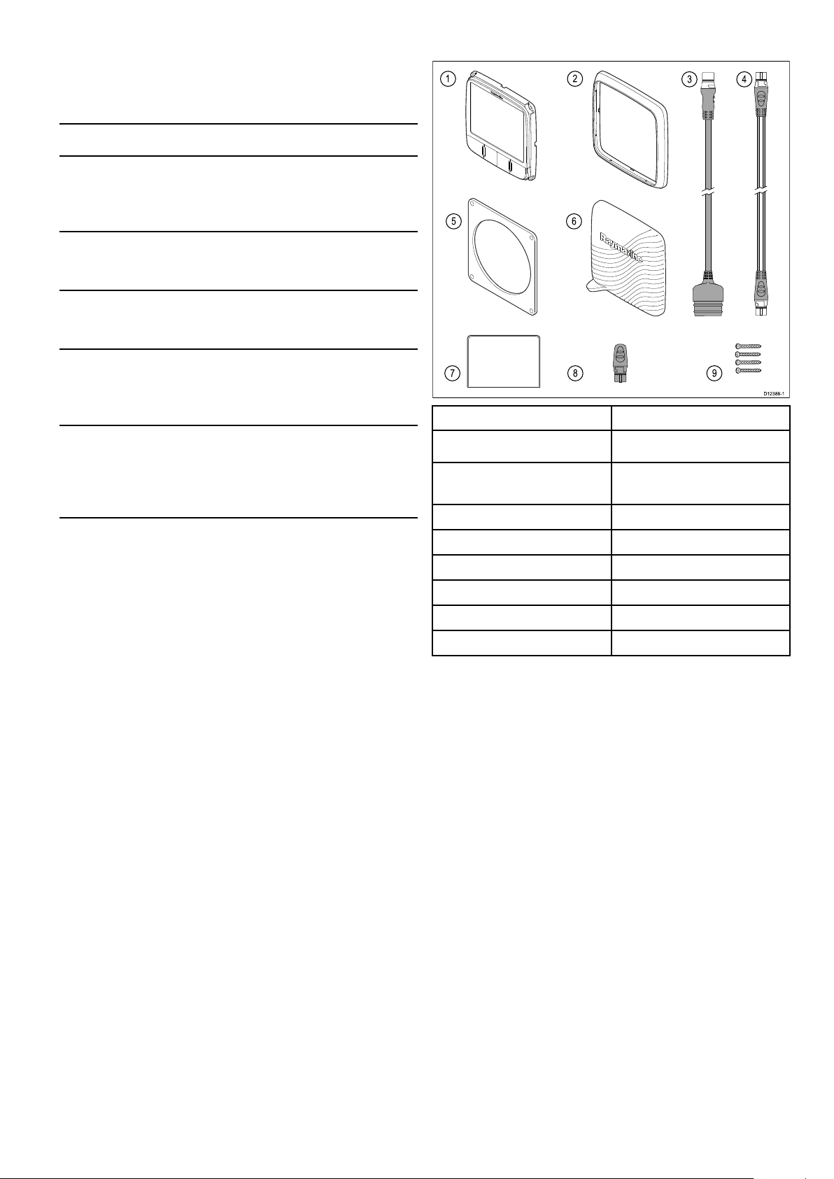
2.2Partssupplied
i50Installationandoperation
instructions
Installationandoperationinstructions
forthei50instrumentdisplay
i50Mountingtemplate
Surfacemountingtemplateforthei50
instrumentdisplay
RotavectaInstallationinstructions
Installationinstructionsforthe
Rotavectawindtransducer
Short&longarmwindvane
Installationinstructions
Installationinstructionsfortheshortand
longarmwindvanetransducers
DepthandSpeedTransducer
installationinstructions
Installationinstructionsforspeedand
depthtransducers,assuppliedwith
yourtransducer
81341/88009
87130
87221/88036
87220/88035
1i50instrument
2Frontbezel
3
SeaTalktoSeaTalk
ng
adaptor
cable
4
5
6
SeaTalk
Gasket
Suncover
ng
spurcable
7
8
9
Documentationpack
SeaTalk
ng
4xxingscrews
blankingplug
Handbookinformation13
Page 14
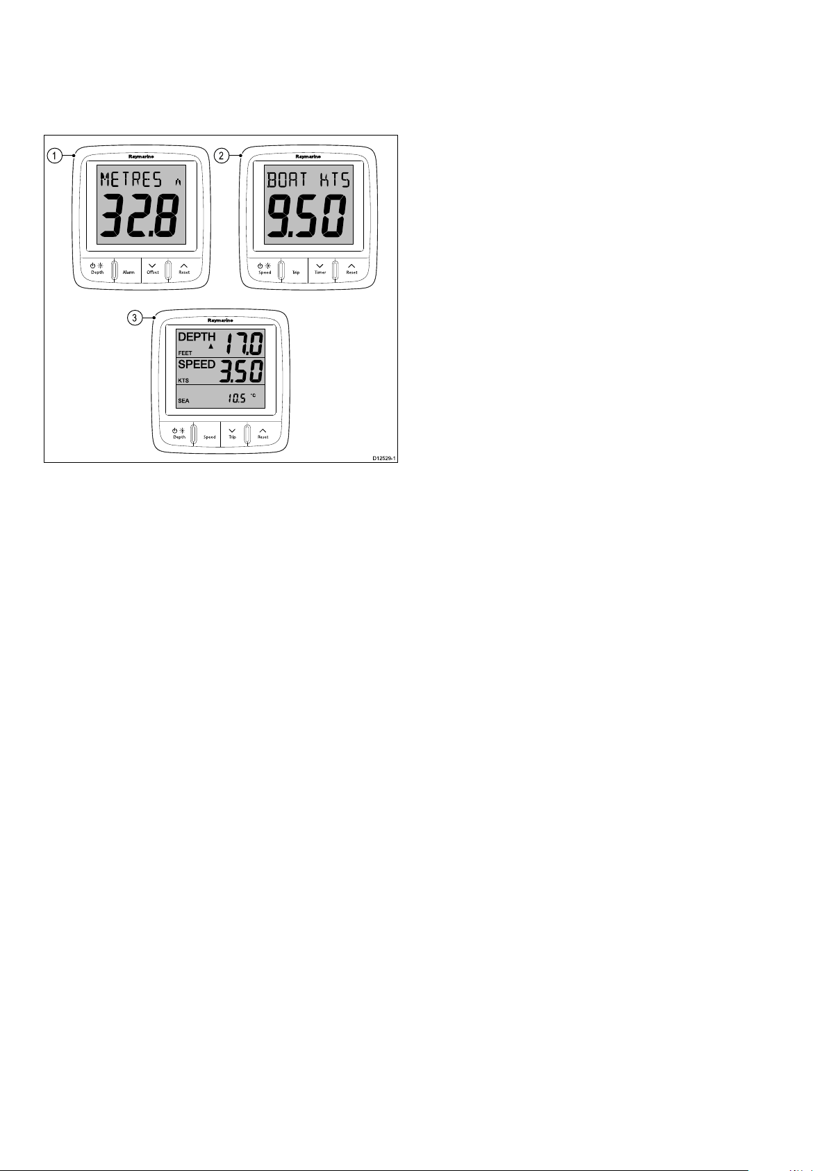
2.3i50Productoverview
ResetSpeedDepth Trip
ResetAlarmDepth Ose t
ResetTripSpee d Tim er
1 2
3
D1252 9-1
Thei50rangeofSeaT alk
ng
instrumentdisplayscan
beconnecteddirectlytotherelevanttransducers.
ThedatacanbetransmittedontheSeaTalk
networktoothercompatibledisplays.
ng
1.i50Depth
2.i50Speed
3.i50Tridata
Thei50instrumentdisplayrangeoffersthefollowing
features:
•IntegrateswithRaymarineautopilotsand
navigationequipmentontheSeaT alk
•Surfacemountable
•Extralarge(28mmmax)digits
•Providesgoodvisibilityinalllightingconditions
•Lowpowerconsumption
ng
network
14
i50
Page 15

Chapter3:Planningtheinstallation
Chaptercontents
•3.1Installationchecklistonpage16
•3.2Compatibletransducersonpage16
•3.3Typicalsystemsonpage18
•3.4Systemprotocolsonpage20
•3.5T oolsrequiredonpage20
•3.6Selectingadisplaylocationonpage21
•3.7Productdimensionsonpage22
•3.8Selectingatransducerlocationonpage22
Planningtheinstallation
15
Page 16

3.1Installationchecklist
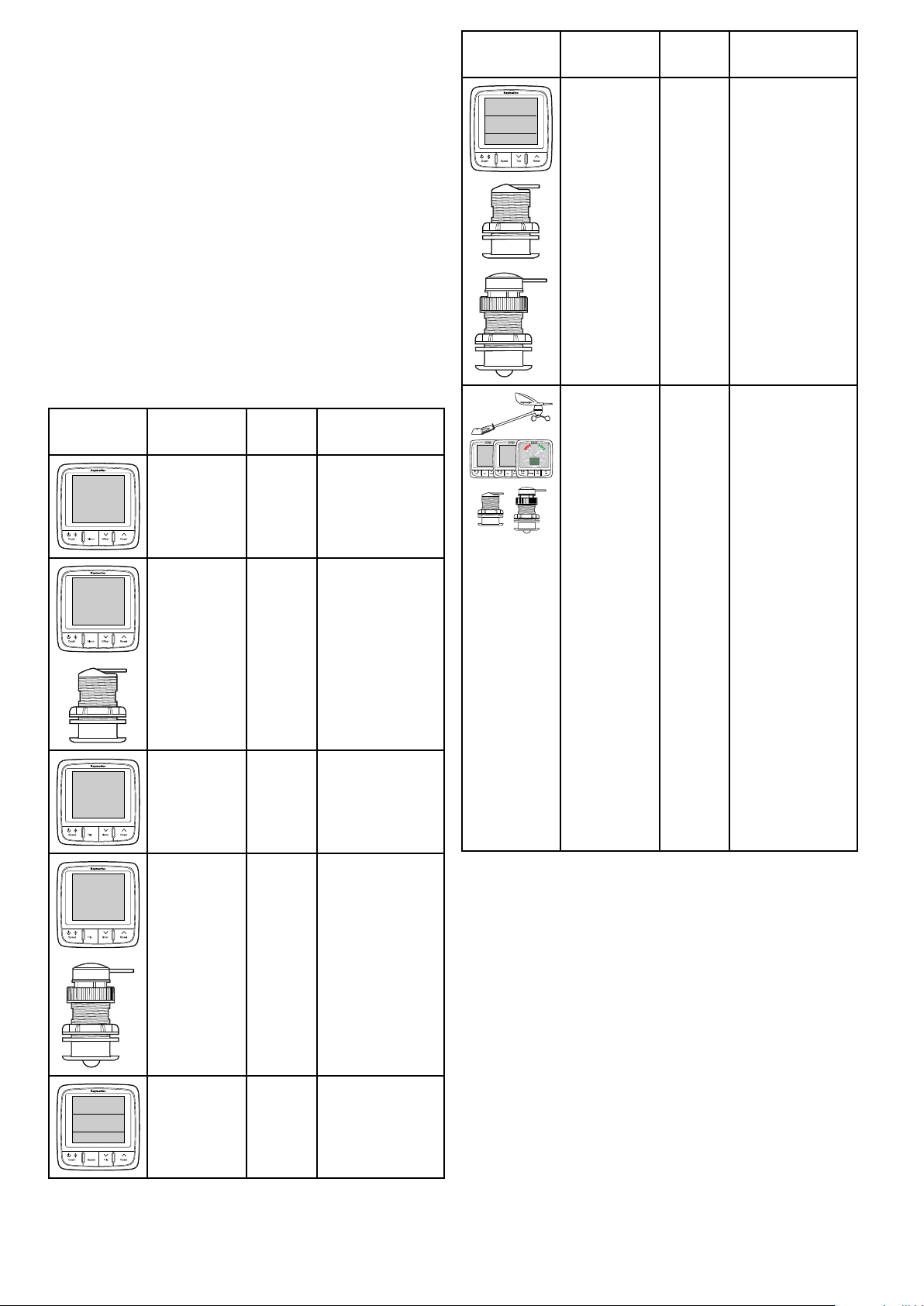
3.2Compatibletransducers
Installationincludesthefollowingactivities:
InstallationTask
1Planyoursystem.
2
Obtainallrequiredequipmentandtools.
3
Siteallequipment.
4Routeallcables.
5
Drillcableandmountingholes.
6Makeallconnectionsintoequipment.
7
Secureallequipmentinplace.
8Poweronandtestthesystem.
Schematicdiagram
Aschematicdiagramisanessentialpartofplanning
anyinstallation.Itisalsousefulforanyfuture
additionsormaintenanceofthesystem.The
diagramshouldinclude:
•Locationofallcomponents.
•Connectors,cabletypes,routesandlengths.
InstrumentDepthtransducers
Thedepthtransducerslistedbelowarecompatible
withthefollowinginstrumentdisplays:
•i40Depth/i40Bidata
•i50Depth/i50Tridata
•i70viaiTC-5converter
Part
numberImageMountingHousing
E26009Thru-hullP7
E26019–
PZ
M78717Thru-hullB17
Thru-hull
B45(including
fairingblock)
M78713–
PZ
E26030Thru-hullP17
E26001–
PZ
E26027–
PZ
Thru-hullP319
In-hullP79
Transom
mount
P66
InstrumentSpeedandT emperature
transducers
Thespeedandtemperaturetransducerslistedbelow
arecompatiblewiththefollowinginstrumentdisplays:
•i40Speed/i40Bidata
•i50Speed/i50Tridata
•i70viaiTC-5converter
16i50
Page 17

Part
numberImageMountingHousing
Part
numberImageMountingHousing
E26008Thru-hullP371
E26005Transom
mount
E26031Thru-hull
M78716Thru-hullB120
A26044Thru-hullB744VL
(including
fairingblock)
E26028–
ST69
PZ
Transom
P66
mount
P120/ST800
E25025Thru-hullP17
InstrumentDepth,SpeedandT emperature
(DST)transducers
TheDSTtransducerslistedbelowarecompatible
withthefollowinginstrumentdisplays:
•i40Depth/i40Speed/i40Bidata
•i50Depthi50Speed/i50Tridata
•i70viaiTC-5converter
Part
numberImageMountingHousing
E26006–
PZ
Transom
mount
P66/ST40
A26043Thru-hullB744V
Planningtheinstallation
(including
fairingblock)
17
Page 18

3.3Typicalsystems
S
S
M
M
A
A
R
R
T
T
P
P
I
I
L
L
O
O
T
T
D1237 3-1
12 V / 24 V dc
12 V dc
SeaTalk
ng
1 2
6
10 11
8 9
5
7
3
4
TheinstrumentrangecanbeconnecteddirectlytoaSeaTalk
connectedtoaSeaT alksystemusingtheSeaT alktoSeaTalk
BasicSeaT alk
1
2
ng
systemexample
SeaTalk
SeaTalk
ng
network.Theinstrumentrangecanalsobe
ng
adaptorcable.
ng
instrumentdisplay
ng
pilotcontroller
3i60Windinstrument
4Raymarinewindvanetransducer
5
6
7
8
9i50Depthinstrument
10
11Depthtransducer
Raymarinemultifunctiondisplay
12/24Vdcpowersupply
Raymarinecoursecomputer(providing12Vdcpowersupply
totheSeaTalk
i50Speedinstrument
Speedtransducer
ng
network.)
18i50
Page 19

ExtendedSeaT alk
S
S
M
M
A
A
R
R
T
T
P
P
I
I
L
L
O
O
T
T
12 V
D1237 4-1
10
12
11 11
1 2 2 3 4 5
17
6 7 8
16
9
11
1514
13
18 19
ng
systemexample
1
2
3Fluxgatecompass
4
5
6
7
8
9Manoverboard
10
11
12
13
14i60Windinstrument
15i50Depthinstrument
16
SeaTalk
SeaTalk
Rudderreference
Raymarinecoursecomputer(providing12Vdcpowersupply
toSeaTalk
12/24Vdcpowersupply
RaymarineAIStransceiver
RaymarineSeaTalk
SeaTalktoSeaTalk
SeaTalk
Raymarinemultifunctiondisplay
Enginedata(viadevicenetadaptorcable.)
i50Speedinstrument
ng
pilotcontroller
ng
instrumentdisplays
ng
network.)
ng
GPS
ng
converter
ng
5wayblocks
17Raymarinewindvanetransducer
18Depthtransducer
19
Planningtheinstallation
Speedtransducer
19
Page 20

3.4Systemprotocols
D1253 0-1
3
4
2
1
5
3.5Toolsrequired
Yourproductcanbeconnectedtovariousproducts
andsystemstoshareinformationandsoimprove
thefunctionalityoftheoverallsystem.These
connectionsmaybemadeusinganumberof
differentprotocols.Fastandaccuratedatacollection
andtransferisachievedbyusingacombinationof
thefollowingdataprotocols:
•SeaTalk
ng
•NMEA2000
•SeaTalk
Note:Y oumayndthatyoursystemdoesnot
usealloftheconnectiontypesorinstrumentation
describedinthissection.
Seatalk
SeaTalk
ng
ng
(NextGeneration)isanenhancedprotocol
forconnectionofcompatiblemarineinstruments
andequipment.ItreplacestheolderSeaTalkand
SeaTalk
SeaTalk
2
protocols.
ng
utilizesasinglebackbonetowhich
compatibleinstrumentsconnectusingaspur.Data
andpowerarecarriedwithinthebackbone.Devices
thathavealowdrawcanbepoweredfromthe
network,althoughhighcurrentequipmentwillneed
tohaveaseparatepowerconnection.
SeaTalk
ng
isaproprietaryextensiontoNMEA2000
andtheprovenCANbustechnology.Compatible
NMEA2000andSeaTalk/SeaTalk
2
devicescan
alsobeconnectedusingtheappropriateinterfaces
oradaptorcablesasrequired.
Toolsrequiredforinstallation
1Pozi-drivescrewdriver
2File
3
92mm(3.62in)holecutter
4Adhesivetape
5
Powerdrill
NMEA2000
NMEA2000offerssignicantimprovementsover
NMEA0183,mostnotablyinspeedandconnectivity.
Upto50unitscansimultaneouslytransmitand
receiveonasinglephysicalbusatanyonetime,
witheachnodebeingphysicallyaddressable.The
standardwasspecicallyintendedtoallowfor
awholenetworkofmarineelectronicsfromany
manufacturertocommunicateonacommonbusvia
standardizedmessagetypesandformats.
SeaTalk
SeaTalkisaprotocolwhichenablescompatible
instrumentstoconnecttoeachotherandsharedata.
TheSeaT alkcablesystemisusedtoconnect
compatibleinstrumentsandequipment.Thecable
carriespoweranddataandenablesconnection
withouttheneedforacentralprocessor.
Additionalinstrumentsandfunctionscanbeaddedto
aSeaTalksystem,simplybypluggingthemintothe
network.SeaT alkequipmentcanalsocommunicate
withothernon-SeaT alkequipmentviatheNMEA
0183standard,providedasuitableinterfaceisused.
20i50
Page 21

3.6Selectingadisplaylocation
Dxxxxx-1
70°
70°
70°
70°
Warning:Potentialignitionsource
ThisproductisNOTapprovedforusein
hazardous/ammableatmospheres.Do
NOTinstallinahazardous/ammable
atmosphere(suchasinanengineroom
ornearfueltanks).
Generallocationrequirements
Whenselectingalocationfortheunititisimportant
toconsideranumberoffactors.
Ventilationrequirements
Toprovideadequateairow:
•Ensurethatequipmentismountedina
compartmentofsuitablesize.
•Ensurethatventilationholesarenotobstructed.
•Ensureadequateseparationofequipment.
Mountingsurfacerequirements
Viewingangle
Ensureunitsareadequatelysupportedonasecure
surface.DoNOTmountunitsorcutholesinplaces
whichmaydamagethestructureofthevessel.
Cableroutingrequirements
Ensuretheunitismountedinalocationwhichallows
properroutingandconnectionofcables:
•Minimumcablebendradiusof100mm(3.94in)is
requiredunlessotherwisestated.
•Usecablesupportstopreventstresson
connectors.
Electricalinterference
Selectalocationthatisfarenoughawayfrom
devicesthatmaycauseinterference,suchas
motors,generatorsandradiotransmitters/receivers.
Magneticcompass
Whenchoosingasuitablelocationyoushouldaim
tomaintainthemaximumpossibledistancebetween
theunitandanycompasses.
Topreventpotentialinterferencewiththevessel's
magneticcompasses,ensurethataminimum
distanceof230mm(9in)betweentheunitandany
installedcompassesismaintained.
Viewingangleconsiderations
Asdisplaycontrast,colorandnightmode
performanceareallaffectedbytheviewingangle,
Raymarinerecommendsyoutemporarilypowerup
thedisplaywhenplanningtheinstallation,toenable
youtobestjudgewhichlocationgivestheoptimum
viewingangle.
Planningtheinstallation
21
Page 22

3.7Productdimensions
D1238 9-1
A C G
D E
B
F
D4349-2
1
2
3
D435 0-5
3.8Selectingatransducerlocation
Generalspeedanddepthtransducerlocation
requirements
Whenselectingalocationforyourtransduceritis
importanttoconsideranumberoffactors.
Thetransducershouldbemountedwithintheclear
waterowareasindicatedbytheshadedareasin
theimagebelow.
A
B
C14mm(0.55”)
D
E
F
G17mm(0.67”)
110mm(4.22”)
115mm(4.52”)
30mm(1.18”)
35mm(1.38”)
90mm(3.54”)
1
Sailingvessel
2Planingpowervessel
3Displacementpowervessel
Eachtransducershouldalso:
•Beaheadofthepropellers(byaminimumof10%
ofthewaterlinelength).
•Beatleast150mm(6in)awayfromthekeel
(ideallyaheadofthekeelonasailingyacht).
•Beasnearaspossibletothecenterlineofthe
vessel.
•Beclearofotherthrough-hullttingsorprojections.
•Havesufcientclearanceinsidethehulltotthe
nut.
•Have100mm(4in)ofheadroomtoallowfor
withdrawal.
Note:Inadditiontotheaboverequirements,the
depthtransducermustbemountedwithin10ºof
thevertical.
22
i50
Page 23

Chapter4:Cablesandconnections
Chaptercontents
•4.1Generalcablingguidanceonpage24
•4.2Powerconnectiononpage24
•4.3SeaT alk
•4.4Transducerconnectionsonpage26
•4.5iTC-5connectiononpage27
•4.6SeaT alkconnectiononpage27
•4.7NMEA2000connectiononpage28
ng
connectionsonpage25
Cablesandconnections23
Page 24

4.1Generalcablingguidance
100 mm (4 in)
200 mm (8 in)
+
_
D13137-1
2
1
4
3
SeaTalk
ng
D12391-2
1 2
8
6
3 54
7
12 V dc
4.2Powerconnection
Cabletypesandlength
Itisimportanttousecablesoftheappropriatetype
andlength
•Unlessotherwisestateduseonlystandardcables
ofthecorrecttype,suppliedbyRaymarine.
•Ensurethatanynon-Raymarinecablesareofthe
correctqualityandgauge.Forexample,longer
powercablerunsmayrequirelargerwiregauges
tominimizevoltagedropalongtherun.
Routingcables
Cablesmustberoutedcorrectly,tomaximize
performanceandprolongcablelife.
•DoNOTbendcablesexcessively .Wherever
possible,ensureaminimumbenddiameterof200
mm(8in)/minimumbendradiusof100mm(4in).
PowerissuppliedtotheproductovertheSeaT alk
network.
ASeaTalk
connectedtotheSeaT alk
ng
systemrequiresone12Vdcsupply ,
ng
backbone.Thiscanbe
provided:
•Byabatteryviathedistributionpanel,or
•FromaRaymarinecoursecomputer,viaaSeaT alk
oraSeaT alk
ng
system.
Warning:Groundingnotrequired
Thisproductisfullyinsulatedanddoes
NOTrequireseparategrounding.
Warning:Positivegroundsystems
Donotconnectthisunittoasystemwhich
haspositivegrounding.
Powerconnection
Directpowerconnection
ng
•Protectallcablesfromphysicaldamageand
exposuretoheat.Usetrunkingorconduitwhere
possible.DoNOTruncablesthroughbilgesor
doorways,orclosetomovingorhotobjects.
•Securecablesinplaceusingtie-wrapsorlacing
twine.Coilanyextracableandtieitoutoftheway.
•Whereacablepassesthroughanexposed
bulkheadordeckhead,useasuitablewatertight
feed-through.
•DoNOTruncablesneartoenginesoruorescent
lights.
Alwaysroutedatacablesasfarawayaspossible
from:
•otherequipmentandcables,
•highcurrentcarryingacanddcpowerlines,
•antennae.
Strainrelief
Ensureadequatestrainreliefisprovided.Protect
connectorsfromstrainandensuretheywillnotpull
outunderextremeseaconditions.
Cableshielding
1
3Acircuitbreakerorfuse
212Vdcvesselpowersupply
3Vessel’sRFground
4
SeaTalk
ng
powercable
Example
Ensurethatalldatacablesareproperlyshielded
thatthecableshieldingisintact(e.g.hasn’tbeen
scrapedoffbybeingsqueezedthroughatightarea).
24
1
2
SeaTalk
SeaTalk
ng
instrument
ng
Pilotcontroller
312Vdcvesselpowersupply.
i50
Page 25

4
D1205 6-1
12Vdcpositive(+)
4.3SeaTalk
ng
connections
5
6
7
In-line5Afuse
SeaTalk
ng
powercable
12Vdcnegative(-)
8Vessel’sRFground
SeaTalk
ng
powerprotection
Thepowersupplymustbeprotectedbya5Afuse
oracircuitbreakerprovidingequivalentprotection.
Raymarinerecommendsthatthepowerisconnected
toaSeaTalk
ng
systeminsuchawaythatthecurrent
drawnoneachsideofthepowerconnectionpoint
isequal.
SeaTalk
ng
powercables
PartnumberDescription
A06049
SeaTalk
ng
powercable
Theunithas2xSeaT alk
connectingtoaSeaT alk
ng
connectorsontherearfor
ng
network.
ConnectingSeaTalk
ng
cables
1.Rotatethelockingcollaronthebackoftheunitto
theUNLOCKEDposition.
2.Ensurethespurcableendconnectoriscorrectly
oriented.
3.Fullyinsertthecableconnector.
4.Rotatelockingcollarclockwise(2clicks)untilit
snapsintotheLOCKEDposition.
Cablesandconnections25
Page 26
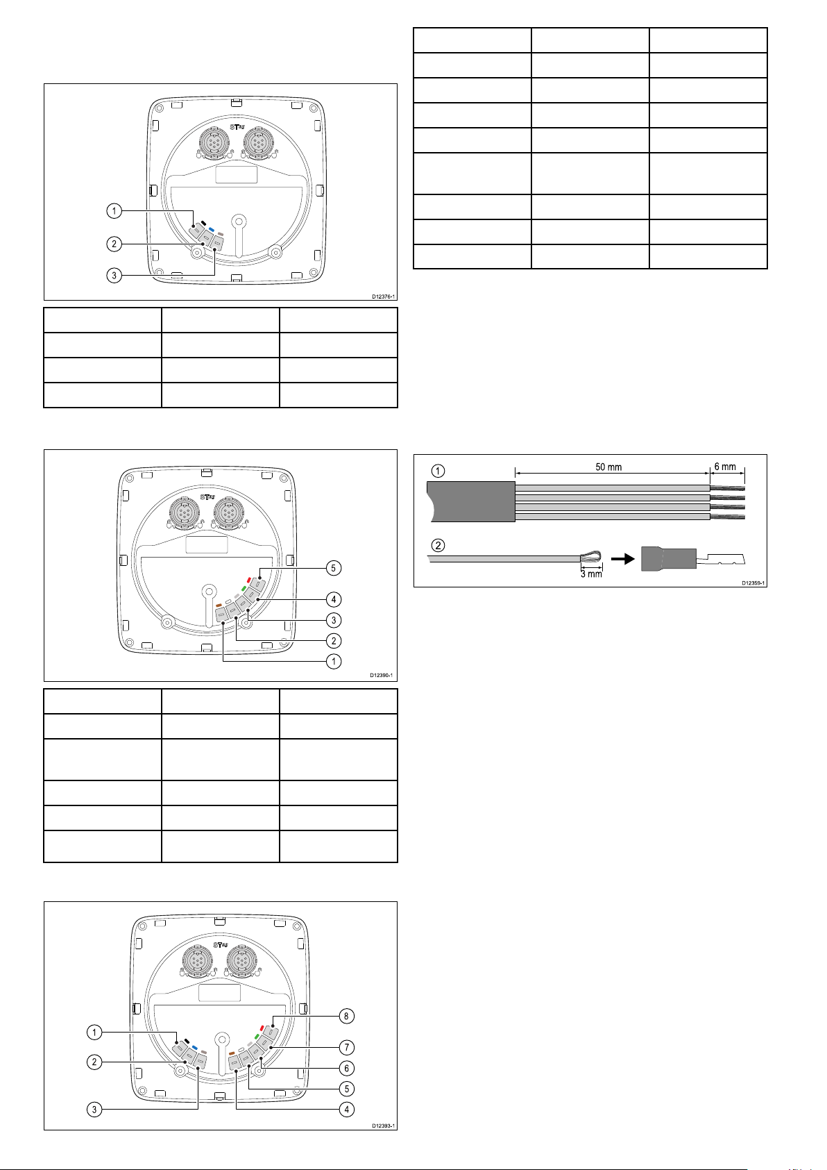
4.4Transducerconnections
D1237 6-1
2
1
3
D1239 0-1
4
5
1
2
3
7
8
4
5
6
D1239 3-1
2
1
3
3 mm
6 mm
50 mm
1
2
D1235 9-1
ItemCablecolorSignalname
i50Depthconnection
ItemCablecolorSignalname
1BlackPiezoceramic–
2BluePiezoceramic+
3
Screen0V(shield)
i50Speedconnection
1
2
3
4
5
Black(Depth)
Blue(Depth)
Screen(Depth)0V(shield)
Brown(Speed)
White(Speed)
Piezoceramic–
Piezoceramic+
Temperature0V
Temperature
(signal)
6
7
8
Screen(Speed)Speed0V(shield)
Green(Speed)Speed(signal)
Red(Speed)SpeedV+
Makingtransducerconnections
Althoughthetransducercableisttedwithspade
connectorsfordirectconnectiontotherearofthe
unit,itmaybenecessarytoremovethesetofacilitate
installation,e.g.ifthecablehastoberoutedthrough
narrowapertures.1/8thspadeterminalswillbe
required(notsupplied),toreplacethoseremoved.
Whenttingthenewspadeconnectors,preparethe
cablesasdetailedbelow:
ItemCablecolorSignalname
1BrownTemperature0V
2WhiteTemperature
(signal)
3
4
5
ScreenSpeed0V(shield)
GreenSpeed(signal)
Red
SpeedV+
i50Tridataconnection
1.Preparethecableasshownin1above.
2.Foldbackthewirestrandsandinsertintothenew
spadeconnectorasshownin2above.
3.Ensurethewirestrandsdonotextendbeyond
therearofthespadeconnectorinsulation.
4.Crimptheconnectortothewire.
26i50
Page 27

4.5iTC-5connection
12 V
D1203 3-3
1 2 3 4
5
6 7 8
12 V dc
12 / 24 V dc
D1205 8-2
98
11 12
4
1 2 3
7
5
6 6 7
10
4.6SeaTalkconnection
TransducerscanbeconnectedtoaSeaTalk
networkusingRaymarine'sInstrumenttransducer
converter(iTC-5)andani70instrument,thedata
canthenberepeatedonani50/i60unit.
ng
ConnectionstoanexistingSeaT alksystemmustbe
madeusingaSeaTalktoSeaT alk
ng
adaptorcable.
BasicSeaTalksystemexample
1
2
3
4
5
i50Depth(Repeater)
i70Instrument(Master)
i50Speed(Repeater)
i60Wind(Repeater)
iTC-5
6Depthtransducer
7
8
Windvanetransducer
Speedtransducer
Note:TransducersconnectedtotheiTC-5mustbe
calibratedusingani70(master)unit.Transducers
connectedtotheiTC-5cannotbecalibratedusing
ani50/i60.
MakingiTC-5transducerconnections
Forinstructionsonconnectingtransducerstoyour
iTC-5refertotheiTC-5handbook.
1i70Instrumentdisplay
(SeaTalk
2
i50Speedinstrument
(SeaTalk
ng
)
ng
)
3i50Depthinstrument
(SeaTalk
ng
)
4Raymarinewindvane
transducer
5
6
7
i60Windinstrument
(SeaTalk
SeaTalk
ng
)
ng
cables
SeaTalktoSeaTalk
ng
adaptor
cables
8
Speedtransducer
9Depthtransducer
10
11
12/24Vdcpowersupply
SeaTalkCoursecomputer
(providing12Vdcpowerto
SeaTalknetwork.)
Cablesandconnections
12
SeaTalkpowerprotection
ST6002pilotcontroller
(SeaTalk)
Thepowersupplymustbeprotectedbya5Afuse
oracircuitbreakerprovidingequivalentprotection.
Raymarinerecommendsthatthepowerisconnected
toaSeaT alksysteminsuchawaythatthecurrent
drawnoneachsideofthepowerconnectionpoint
isequal.
27
Page 28

SeaTalkpowercables
12V NMEA 2000
SeaTalk
ng
D1238 0-1
3
1
2
4
D123 77-1
1
4
2
3
4.7NMEA2000connection
PartnumberDescription
D229
SeaTalkpowercable.
Youcaneither:
•UseyourSeaT alk
ng
backboneandconnecteach
NMEA2000deviceonaspur,OR
•connecttheinstrumentdisplayonaspurintoan
existingNMEA2000backbone.
Important:Y oucannothaveany2terminated
backbonesconnectedtogether,unlessyouhave
anisolationgatewaybetweenthetwobackbones.
ConnectingNMEA2000equipmenttothe
SeaTalk
ng
backbone
1.12Vdcpowersupplyintobackbone.
2.SeaTalk
3.SeaTalk
ng
backbone.
ng
toDeviceNetadaptorcable.
4.NMEA2000equipment.
ConnectingtheunittoanexistingNMEA2000
(DeviceNet)backbone
1.SeaTalk
2.SeaTalk
28i50
3.DeviceNetbackbone.
4.NMEA2000equipment.
ng
instrumentdisplay
ng
toDeviceNetadaptorcable.
Page 29

Chapter5:Mounting
Chaptercontents
•5.1Mountingonpage30
•5.2Frontbezelonpage31
Mounting
29
Page 30

5.1Mounting
D1237 9-1
Pre-mountingcheck
Theproductisdesignedtobesurfacemounted.
Beforemountingtheunit,ensureyouhave:
•Selectedasuitablelocation.
•Identiedthecableconnectionsandroutethatthe
cableswilltake.
•Detachedthefrontbezel.
•Removethekeypadmat.
Mountingdiagram
Note:Thesuppliedgasketprovidesaseal
betweentheunitandasuitablyatandstiff
mountingsurfaceorbinnacle.Thegasketshould
beusedinallinstallations.Itmayalsobe
necessarytouseamarine-gradesealantifthe
mountingsurfaceorbinnacleisnotentirelyatand
stifforhasaroughsurfacenish.
Mountinginstructions
1.Checktheselectedlocationfortheunit,aclear,
atareawithsuitableclearancebehindthepanel
isrequired.
2.Fixthemountingtemplatesuppliedwiththe
product,totheselectedlocation,usingmasking
orselfadhesivetape.
3.Ifpossibleuseanappropriatesizeholecutting
sawandcutoutthecentreholecutoutareaas
indicatedonthemountingtemplate,or
4.Usingasuitableholecuttingsaw,makepilot
holesineachcornerofthecutoutareaandusing
ajigsawcutalongtheinsideedgeofthecutout
line.
5.Ensurethattheunittsintotheremovedarea
andthenlearoundthecutedgeuntilsmooth.
6.Drillanyrequiredholesasindicatedonthe
mountingtemplateforthesecuringscrews.
7.Connecttherelevantcablestotheunit.
8.Peelthebackingoffofthesuppliedgasketand
placetheadhesivesideofthegasketontothe
displayunitandpressrmlyontotheange.
9.Slidetheunitintoplaceandsecureusingthe
screwsprovided.
10.Retkeypadmatandfrontbezel.
Note:Drill,tapsizeandtighteningtorquesare
dependantuponthematerialtypeandthickness
ofthemountingsurface.
30i50
Page 31

5.2Frontbezel
D1237 2-1
1 2
3 4
Removingthefrontbezel
Note:Usecarewhenremovingthebezel.Donot
useanytoolstoleverthebezel,doingsomay
causedamage.
1.Usingyourngerspullthebezelawayfromthe
unitatthetopandside,asshownin2.
Thebezelwillstarttocomeawayfromtheunitat
thetopandside.
2.Nowpullthebezelawayfromtheunitonthe
oppositeside,asshownin3.
Thebezelwillnowcomefreefromtheunit,as
shownin4.
Mounting
31
Page 32

32i50
Page 33

Chapter6:i50Depth
Chaptercontents
•6.1i50Depthoperationonpage34
•6.2i50Depthcontrolsonpage34
•6.3Poweronpage35
•6.4Datamasteronpage35
•6.5Calibrationonpage36
•6.6UserCalibration-i50Depthonpage36
•6.7Intermediatecalibration—i50Depthonpage37
•6.8Dealercalibration—i50Depthonpage38
•6.9Usingthedepthpagesonpage39
•6.10Viewingthedepthoffsetonpage39
•6.11Alarmsonpage40
•6.12Illuminationonpage41
i50Depth
33
Page 34

6.1i50Depthoperation
Dep th Alarm Offse t Re se t
D13144-1
1 2 3 4
Whenconnectedtotherelevantdepthtransducer,
youri50depthinstrument:
•Providescurrentdepthinformation,ineitherfeet
(ft),metres(M)orfathoms(FA).
•Recordstheminimumandmaximumdepth
encounteredduringtheperiodtheunitisswitched
on.
•Enablesyoutodenealarmthresholdsforshallow
alarm,deepalarm,shallowanchoralarmand
deepanchoralarm.
•Enablesyoutoseewhatoffsethasbeenapplied
tothedepthreading.
Note:Depthinformationisobtainedfromthedepth
transducerconnectedtotheunit.However,when
theinstrumentisconnectedtoaSeaTalknetwork,
whichcontainsacompatiblesonarmodule
(shnder)thedepthinformationisprovidedbythe
sonarmodule,whilstitisswitchedon.
Itshouldbenotedthat:
•TherequireddepthunitsareselectedduringUser
calibration.
•Up/Downdepth-trendarrowsaredisplayed,ifthe
seabedisrisingorfalling.
•Ifforanyreasondepthinformationislost,the
depthtitlewillashandthedisplayedvaluewillbe
thelastknowndepthreading.
6.2i50Depthcontrols
1
2
3
4
Depth/Power—Selecttoaccessdepth
information,adjustbacklight,adjustcontrastand
powerthedisplayOnandOff
Alarm—Selecttoaccessalarmlevelsandalarm
settings
Offset/Down—Selecttoaccessdepthoffset
settings.Usetomovedownthroughmenuoptions
ortodecreasenumericvalues
Reset/Up—Selectandholddownfor3seconds
toresetdatatocurrentvalues.Usetomoveup
throughmenuoptionsortoincreasenumericvalues
34i50
Page 35

6.3Power
10
15
20
25
30
35
40
45
50
55
60
5
4
+
D12451-2
Dep th
Alarm
Dep th
6.4Datamaster
Poweringontheunit
Withpowertotheunitturnedonbuttheunitswitched
off:
1.PressandholdthePowerbuttonuntiltheunit
powersonanddataisdisplayed(approximately
2seconds).
Note:Whenpowertotheunitisturnedontheunit
willswitchonautomatically.
Poweringofftheunit
1.PressandholdthePowerbuttonuntilthepower
countdowntimerisdisplayedandreacheszero
(approximately6to8seconds).
Whereasystemcontainsmorethanoneunit
capableofdisplayingadatatype,theunitphysically
connectedtothetransducermustbesetasthedata
masterandanyotherunitssetasarepeater.
Checkingi50Depthsoftwareversionand
status
Duringnormaloperation:
1.PressandholdtheDepthandAlarmbuttonsat
thesametimeforapproximately4seconds,until
theSoftwareVersionpageisdisplayed.
2.PresstheDepthbuttontodisplaytheInstrument
Statuspage.
Master(transducerconnected)orRepeater(No
transducerconnected).
3.T ochangethestatus:
i.PresstheOffsetandResetbuttonsatthe
sametime.
Thestatuswillash.
ii.PresseithertheOffsetorResettochange
thestatusbetweenMasterorRepeater.
i.PresstheOffsetandResetbuttonsatthe
sametimetoconrmthestatus.
4.T oexittheIntermediatecalibrationsettingsat
anytime,pressandholdtheDepthandAlarm
buttonsatthesametimeforapproximately4
secondstoreturntonormaloperation.
i50Depth
35
Page 36

6.5Calibration
+
D12421-2
10
15
20
25
30
35
40
45
50
55
60
5
2
Depth
Alarm
D12422-2
Depth
6.6UserCalibration-i50Depth
Beforerstusecalibrationproceduresmustbe
carriedouttoensureoptimumperformanceofthe
instrumentwiththevessel.
Thecalibrationproceduresare:
•Usercalibration
•Intermediatecalibration
•Dealercalibration
Usercalibrationoptionsinclude:
•Unitsfordepthreadings—Assignstheunitof
measureusedfordepthrelatedreadings.
•*Depthoffset—Assignsanoffsettothedepth
reading.
Note:*Thesesettingsareonlyavailableon
displayswhentheinstrumentstatusissetto
Master(seeIntermediateCalibrationfordetailsof
changingthedisplaytobeMasterorRepeater).
AccessingtheUserCalibrationMenu
Duringnormaloperation:
1.PressandholdtheDepthandAlarmbuttonsat
thesametimeforapproximately2seconds,until
theUserCalibrationpageisdisplayed.
Note:Theusercalibrationpagewilltime-outafter
8secondsofinactivity.
2.UsetheDepthbuttontocyclethroughthe
availablesettings.
Note:Toexittheusercalibrationpagesatany
time,pressandholdtheDepthandAlarmbuttons
atthesametimeforapproximately2seconds.
Selectingtheunitofmeasurefordepth
readings
FromtheUserCalibrationMenu:
1.PresstheDepthbuttonuntiltheDepthUnits
pageisdisplayed(1pressfromtheUser
Calibrationentrypage).
2.UsetheOffsetandResetbuttonstoselectthe
requiredunitofmeasurementfordepthreadings.
Theunitsofmeasureavailablefordepthreadings
are:
•FEET(default)
•METRES
•FATHOMS
Note:Toexittheusercalibrationpagesatany
time,pressandholdtheDepthandAlarmbuttons
atthesametimeforapproximately2seconds.
DepthOffset
Depthsaremeasuredfromthetransducertothesea
bed,butyoucanapplyanoffsetvaluetothedepth
data,sothatthedisplayeddepthreadingrepresents
36i50
thedepthtotheseabedfromeitherthekeelorthe
waterline.
Page 37

Beforeattemptingtosetawaterlineorkeel
D9343--2
1 2 3
D12423-2
Depth
10
15
20
25
30
35
40
45
50
55
60
5
4
+
D12451-2
Dep th
Alarm
Dep th
offset,ndouttheverticalseparationbetweenthe
transducerandeitherthewaterlineorthebottomof
thekeelonyourvessel,asappropriate.Thensetthe
appropriatedepthoffsetvalue.
6.7Intermediatecalibration—i50 Depth
Intermediatecalibrationallowsyouto:
•Checktheinstrumentsoftwareversion.
•Checkandifnecessarysettheinstrumentstatus
aseitherMasterorRepeater.
Checkingi50Depthsoftwareversionand
status
1
2
3
Waterlineoffset
Transducer/Zerooffset
Keeloffset
Ifanoffsetisnotapplied,displayeddepthreadings
representthedistancefromthetransducertothe
seabed.
ApplyingaDepthOffset
FromtheUserCalibrationMenu:
1.PresstheDepthbuttonuntiltheDepthOffset
pageisdisplayed(2pressesfromUser
Calibrationentrypage).
2.UsetheOffsetandResetbuttonstoselectthe
requireddepthoffsetvalue.
Thedepthoffsetcanbesettothefollowing
values:
•Keel—valuesbetween–9.9to–0.1
Duringnormaloperation:
1.PressandholdtheDepthandAlarmbuttonsat
thesametimeforapproximately4seconds,until
theSoftwareVersionpageisdisplayed.
2.PresstheDepthbuttontodisplaytheInstrument
Statuspage.
Master(transducerconnected)orRepeater(No
transducerconnected).
3.T ochangethestatus:
i.PresstheOffsetandResetbuttonsatthe
sametime.
Thestatuswillash.
ii.PresseithertheOffsetorResettochange
thestatusbetweenMasterorRepeater.
i.PresstheOffsetandResetbuttonsatthe
sametimetoconrmthestatus.
4.T oexittheIntermediatecalibrationsettingsat
anytime,pressandholdtheDepthandAlarm
buttonsatthesametimeforapproximately4
secondstoreturntonormaloperation.
•OFFSET(default)(ZeroOffset)—0.0
•W/L(Waterline)—valuesbetween0.1to9.9
Note:Toexittheusercalibrationpagesatany
time,pressandholdtheDepthandAlarmbuttons
atthesametimeforapproximately2seconds.
i50Depth
37
Page 38

6.8Dealercalibration—i50Depth
+
D12470-2
10
15
20
25
30
35
40
45
50
55
60
5
14
Dep th
Alarm
D12471-2
+
Offset
Res et
D12472-2
Depth
D12473-2
Depth
D12474-2
Depth
DealerCalibrationenablesyoutoset:
•UsercalibrationmenuaccessOn(default)andOff.
Note:T oexittheDealerCalibrationpagesatany
time,pressandholdtheDepthandAlarmbuttons
atthesametimeforapproximately2seconds.
•DisplayResponsefordepthreadings—Dictates
therateatwhichtheinstrumentdisplayresponds
tochangesindepthdata.
•BoatshowmodeOnandOff(default)(Boat
showmodeisonlyavailableondisplayssetas
repeaters).
•Resettofactorydefaults.
AccessingtheDealerCalibrationMenu
Duringnormaloperation:
1.PressandholdtheDepthandAlarmbuttons
atthesametimeforapproximately14seconds,
untiltheDealerCalibrationpageisdisplayed.
Note:T oexittheDealerCalibrationpagesatany
time,pressandholdtheDepthandAlarmbuttons
atthesametimeforapproximately2seconds.
EnablinganddisablingBoatShowMode
FromtheUserCalibrationMenuAccesspage:
1.PresstheDepthbuttonuntiltheBoatShow
Modepageisdisplayed(2pressesfromUser
CalibrationMenuAccesspage).
2.UsetheOffsetandResetbuttonstoswitchboat
showmodeOnandOff(default).
SelectingOnwillputthedisplayintoboatshow
mode.
Note:Boatshowmodeisonlysuitablefor
demonstrationpurposesandshouldNOTbeused
whilstyourvesselisinuse.
Note:T oexittheDealerCalibrationpagesatany
time,pressandholdtheDepthandAlarmbuttons
atthesametimeforapproximately2seconds.
SettingaccesstotheUserCalibrationMenu
FromtheDealerCalibrationpage:
1.PresstheOffsetandResetbuttonsatthesame
timetodisplaytheUserCalibrationAccess
page.
2.UsetheOffsetandResetbuttonstoswitch
accesstotheUserCalibrationMenu
On(default)andOff.
SelectingOffdisablesaccesstotheUser
CalibrationMenu.
Note:T oexittheDealerCalibrationpagesatany
time,pressandholdtheDepthandAlarmbuttons
atthesametimeforapproximately2seconds.
Settingtheresponsedelayfordepth
readings
FromtheUserCalibrationMenuAccesspage:
1.PresstheDepthbuttonuntiltheDepth
Responsepageisdisplayed(1pressfromthe
UserCalibrationMenuAccesspage).
Resettingthedisplaytofactorydefaults
FromtheUserCalibrationMenuAccesspage:
1.PresstheDepthbuttonuntiltheFactory
Defaultspageisdisplayed(3pressesfromUser
CalibrationMenuAccesspage).
2.T oresetthedisplaytofactorydefaultsettings:
i.UsetheOffsetorResetbuttonstochange
theresetoptiontoY es.
ii.PresstheDepthbuttontoresetyourdisplay
tofactorydefaultsettings.
3.Afteraresetitisrecommendedthatyoucheck
thedatamasterstatusofthedisplaytoensure
itissetcorrectly.Referto6.4Datamasterfor
details.
Note:T oexittheDealerCalibrationpagesatany
time,pressandholdtheDepthandAlarmbuttons
atthesametimeforapproximately2seconds.
2.UsetheOffsetandResetbuttonstoadjustthe
depthresponsetotherequiredlevel.
Thedefaultlevelis12.Thelevelsavailableare1
to15withlevel1beingtheslowestupdaterate
andlevel15thequickest.
38i50
Page 39

6.9Usingthedepthpages
10
15
20
25
30
35
40
45
50
55
60
5
8
10
15
20
25
30
35
40
45
50
55
60
5
8
D12532-2
10
15
20
25
30
35
40
45
50
55
60
5
3
10
15
20
25
30
35
40
45
50
55
60
5
3
1
3 2
Depth
Depth
Depth
Res etRes et
6.10Viewingthedepthoffset
Tocyclethroughthedepthpagesfollowthesteps
below.
1.CurrentDepthpage
2.*MinimumDepthpage
3.*MaximumDepthpage
Note:*Thesepagesaretemporarypagesand
willrevertbacktotheCurrentDepthpageafter
8secondsofinactivity.
1.UsetheDepthbuttontocyclethroughthe
availabledepthpages.
2.FromtheMinimumDepthorMaximumDepth
page,pressandholdtheResetbuttonfor
approximately3secondstoresetthereading.
Toviewtheoffsetvaluecurrentlyappliedtoyour
instrumentfollowthestepsbelow.
Duringnormaloperation:
1.PresstheOffsetbuttontodisplaytheDepth
offsetpage.
Thedisplayshowsthevalueoftheoffsetapplied
andidenties:
•IfapositiveoffsetvalueisappliedW/Lis
displayedtodenoteawaterlineoffset.
•IfanegativeoffsetvalueisappliedKEELis
displayedtodenoteakeeloffset.
•IfazerooffsetvalueisappliedOFFSETis
displayedtodenotethatthereisazerooffset
fromthetransducer.
Note:Depthoffsetinformationisonlyavailable
onunitssetasdatamasters(seeDatamaster
sectionfordetails.
i50Depth
39
Page 40

6.11Alarms
D12542-2
D12543-2
D12545-2
D12544-2
D12546-2
+
-
Offset
Offset
Re set
Re set
+
Alarmsalertyoutoasituationorhazardrequiring
yourattention.
Youcansetupalarmstoalertyoutocertain
conditions.
Alarmsareraisedbysystemfunctions,andalso
externalequipmentconnectedtoyourdisplay.
Whenanalarmeventoccursanaudibleandvisual
alarmisactivatedwhichindicatesthealarmstate.
Alarmthresholdscanbeconguredfromtherelevant
alarmpage/menu.
Instrumentalarms
Thealarmsavailableforthei50Depthandi50
Tridataarelistedbelow.
•Shallowdepthalarm
•Deepdepthalarm
•Shallowanchoralarm
•Deepanchoralarm
Alarmindications
Analarmeventisindicatedbybothaudibleand
visualwarnings.
1.PressandholdtheResetbuttonfor1secondto
switchthealarmonoroff.
Settingalarmthresholds—i50Depth
Youcanadjustthethresholdatwhichalarmsare
triggeredbyfollowingthestepsbelow.
Withtherelevantalarmpagedisplayed:
1.PresstheOffsetandResetbuttonsatthesame
timetochangethealarmthreshold.
Thecurrentthresholdwillstarttoash.
2.UsetheResetbuttontoincreasethealarm
threshold.
3.UsetheOffsetbuttontodecreasethealarm
threshold.
4.Thealarmthresholdpagewilltime-out
afterapproximately6secondsofinactivity,
automaticallysavingthenewalarmthreshold.
Shallowalarm
Deepalarm
Shallowanchoralarm
Deepanchoralarm
Alarmsaresoundedwhenthesetalarmthreshold
valueiscrossed.Alarmswillsounduntilsilenced.
Silencingalarms
1.Pressanybuttontosilenceanactivealarm.
Enabling/Disablingalarms
Alarmscanbeenabledordisabledatanytime.
Withtherelevantalarmpagedisplayed:
40i50
Page 41

6.12Illumination
•FLY—Flybridge
Adjustingthebacklightlevel—i50Depth
Thebacklightinglevelcanbeaccessedusingthe
Depthbutton.
Duringnormaloperation:
1.PressandholdtheDepthbuttonfor
approximately2secondstodisplaytheBacklight
page.
LAMPSisdisplayedon-screenandthecurrent
backlightlevel.
2.UsetheResetbuttontoincreasethebacklight
settingtotherequiredlevel.
3.UsetheOffsetbuttontoincreasethebacklight
settingtotherequiredlevel.
Thebacklightlevelcanbeadjustedfromlevel1to
level9orswitchedOff(default).
Note:Thebacklightpagewilltime-outafter8
secondsofinactivity.
Adjustingthecontrast—i50Depth
Thecontrastlevelcanbeaccessedusingthepower
button.
Duringnormaloperation:
1.PressandholdtheDepthbuttonfor
approximately4secondstodisplaytheContrast
page.
CONTRASTisdisplayedon-screenandthecurrent
contrastlevel.
2.UsetheDepthbuttontocyclethroughthe
availablecontrastlevels.
Thecontrastlevelcanbeadjustedfromlevel
0(default)to3.
Note:Thecontrastpagewilltime-outafter8
secondsofinactivity.
•NST—Mast
•GP1toGP5—Userdenedgroups
Whenassignedtoagroup,whenthebacklightingof
1unitisadjustedthebacklightinglevelofallunits
assignedtothesamegroupwillalsochange.
Assigningthei50Depthtoagroup
Toassignthei50Depthaspartofagroupsothatit
canparticipateingroupilluminationfollowthesteps
below.
Duringnormaloperation:
1.PressandholdtheDepthandAlarmbuttons
atthesametimefor6seconds,untiltheGroup
illuminationpageisdisplayed.
GROUPCALisdisplayedon-screen.
Note:TheGroupilluminationentrypageisa
temporarypageandwilltime-outtotheprevious
pageafter8seconds.
2.PresstheDepthbuttontodisplaytheGroups
page.
3.PresstheOffsetandResetbuttonsatthesame
timetoenableselectionofagroup.
Thegroupsettingwillash.
4.UsetheResetbuttontocycleupwardsthrough
thelistofavailablegroups.
5.UsetheOffsetbuttontocyclebackdownthrough
thelist.
6.PresstheOffsetandResetbuttonsatthesame
timetoassignthedisplaytotheselectedgroup.
Thegroupsettingwillstopashing.
7.PressandholdtheDepthandAlarmbuttonsat
thesametimeforapproximately2secondsto
returntonormaloperation.
Groupillumination
Groupilluminationisusedtosynchronizesand
controlthebacklightinglevelofmultipleunits
assignedtothesamegroup.
Theunitcanparticipateinsharedillumination
viaaSeaT alknetworkorgroupilluminationviaa
SeaTalk
WhenconnectedonaSeaTalknetworkall
compatibleunitswillsharetheirbacklightlevel(when
1unit'sbacklightinglevelisadjustedallotherunits
backlightlevelwillalsochange).
WhenconnectedonaSeaT alk
canparticipateingroupilluminationandbeassigned
toagroupofunitswhichwillsharetheirbacklighting
levels.Availablegroupsareasfollows:
•OFF(default)—Groupilluminationis
•HL1—Helm1
•HL2—Helm2
•CPt—Cockpit
i50Depth
ng
network.
switchedoff
ng
networktheunit
41
Page 42

42
i50
Page 43

Chapter7:i50Speed
Chaptercontents
•7.1i50Speedoperationonpage44
•7.2i50Speedcontrolsonpage44
•7.3Poweronpage45
•7.4Datamasteronpage45
•7.5Calibrationonpage46
•7.6UserCalibration-i50Speedonpage46
•7.7Intermediatecalibration—i50Speedonpage49
•7.8Dealercalibration—i50Speedonpage51
•7.9Usingthespeedpagesonpage52
•7.10Usingthelog,tripandtemperaturepagesonpage53
•7.11Usingthetimersonpage53
•7.12Illuminationonpage54
i50Speed
43
Page 44

7.1i50Speedoperation
Speed Trip Timer Reset
D13145-1
1 2 3 4
Whenconnectedtotherelevantspeedorspeedand
temperaturetransducer,youri50Speedinstrument
provides:
•Current,maximumandaveragespeedinformation,
ineitherknots(KTS),mileperhour(MPH)or
kilometersperhour(KPH).
•Logandtripinformation,ineithernauticalmiles
(NM),statutemiles(M)orkilometers(KM).
•Watertemperatureinformation,ineitherdegrees
celsius(ºC)orfahrenheit(ºF).
•Velocitymadegood(VMG)information,VMG
isonlyavailablewhenconnectedtoSeaT alk
orSeaT alk
compatiblewindtransducer.
•Speedoverground(SOG)information,SOGis
onlyavailablewhenconnectedtoSeaTalkor
SeaTalk
GPS.
ng
networkwhichalsocontainsa
ng
networkwhichalsocontainsasuitable
7.2i50Speedcontrols
1
Speed/Power—Selecttoaccessspeed
information,adjustbacklight,adjustcontrastand
powerthedisplayOnandOff
•Count-upandracestarttimers
Note:Therequiredspeed,distanceand
temperatureunitsareselectedduringUser
calibration.
Itshouldbenotedthat:
•Themaximumspeed,averagespeedandtrip
readingareresettozeroatpowerup.
•Thelogscreenshowsthetotaldistancecovered
bythevesselsincetheunitwastted.
2
Trip—Selecttoaccesslog,tripandwater
temperatureinformation
3
Timer/Down—Selecttoaccesstimers.Useto
movedownthroughmenuoptionsortodecrease
numericvalues
4
Reset/Up—Selectandholddownfor3seconds
toresetdatatocurrentvalues.Usetomoveup
throughmenuoptionsortoincreasenumericvalues
44
i50
Page 45

7.3Power
10
15
20
25
30
35
40
45
50
55
60
5
4
+
D12452-2
Sp eed
Trip
Sp eed
7.4Datamaster
Poweringontheunit
Withpowertotheunitturnedonbuttheunitswitched
off:
1.PressandholdthePowerbuttonuntiltheunit
powersonanddataisdisplayed(approximately
2seconds).
Note:Whenpowertotheunitisturnedontheunit
willswitchonautomatically.
Poweringofftheunit
1.PressandholdthePowerbuttonuntilthepower
countdowntimerisdisplayedandreacheszero
(approximately6to8seconds).
Whereasystemcontainsmorethanoneunit
capableofdisplayingadatatype,theunitphysically
connectedtothetransducermustbesetasthedata
masterandanyotherunitssetasarepeater.
Checkingi50Speedsoftwareversionand
status
Duringnormaloperation:
1.PressandholdtheSpeedandTripbuttonsat
thesametimeforapproximately4seconds,until
theSoftwareVersionpageisdisplayed.
2.PresstheSpeedbuttontodisplaytheinstrument
status.
Master(transducerconnected)orRepeater(No
transducerconnected).
3.PresstheSpeedbuttonagaintobegintheSpeed
RunCalibration.
4.T oexittheIntermediateCalibrationsettingsat
anytime,pressandholdtheSpeedandTrip
buttonsatthesametimeforapproximately4
seconds.
i50Speed
45
Page 46

7.5Calibration
+
D12426-2
10
15
20
25
30
35
40
45
50
55
60
5
2
Spe ed
Trip
D12427-2
Spe ed
7.6UserCalibration-i50Speed
Beforerstusecalibrationproceduresmustbe
carriedouttoensureoptimumperformanceofthe
instrumentwiththevessel.
Thecalibrationproceduresare:
•Usercalibration
•Intermediatecalibration
•Dealercalibration
Usercalibrationoptionsinclude:
•Unitsforspeedreadings—Assignstheunitof
measureusedforspeedrelatedreadings.
•Resolutionforspeedreadings—Assignsthe
layoutofspeedrelatedreadings.
•Unitsforlogreadings—Assignstheunitof
measureusedforlogrelatedreadings.
•Unitsforwatertemperature—Assignstheunitof
measureusedfortemperaturerelatedreadings.
•*Correctspeedreading—Assignsanoffsetto
thespeedreading.
•Timerbuzzer—Switchesthebuzzerwarningon
andoffforthetimer.
Note:*Thesesettingsareonlyavailableon
displayswhentheinstrumentstatusissetto
Master(seeIntermediateCalibrationfordetailsof
changingthedisplaytobeMasterorRepeater).
AccessingtheUserCalibrationMenu
Duringnormaloperation:
1.PressandholdtheSpeedandTripbuttonsat
thesametimeforapproximately2seconds,until
theUserCalibrationpageisdisplayed.
Note:TheUserCalibrationpagewilltime-outafter
8secondsofinactivity.
2.UsetheSpeedbuttontocyclethroughthe
availablesettings.
Note:T oexittheUserCalibrationpagesatany
time,pressandholdtheSpeedandTripbuttons
atthesametimeforapproximately2seconds.
Selectingtheunitofmeasureforspeed
readings
FromtheUserCalibrationMenu:
1.PresstheSpeedbuttonuntiltheSpeedUnits
pageisdisplayed(1pressfromtheUser
Calibrationentrypage).
2.UsetheTimerorResetbuttonstoselectthe
requiredunitofmeasurementforspeedreadings.
Theunitsofmeasureavailableforspeed
readingsare:
•KTS—Knots(default)
•MPH—MilesPerHour
•KMH—KilometersPerHour
Note:T oexittheUserCalibrationpagesatany
time,pressandholdtheSpeedandTripbuttons
46i50
atthesametimeforapproximately2seconds.
Page 47

Selectingaspeedresolution
D12428-2
Spe ed
D12429-2
Spe ed
D12430-2
Spe ed
Spe ed
SOG
SOG
D12432-2
10
15
20
25
30
35
40
45
50
55
60
5
3
Res et
D12431-2
+
Timer
Res et
FromtheUserCalibrationMenu:
1.PresstheSpeedbuttonuntiltheSpeed
Resolutionpageisdisplayed(2pressesfrom
theUserCalibrationentrypage).
2.UsetheTimerorResetbuttonstoselectthe
requiredresolutionforspeedreadings.
Theresolutionsavailableare0.01(default)and
0.1.
2.PresstheSpeedbuttonuntil1oftheCurrent
Speedpagesisdisplayed(4pressesfromthe
UserCalibrationentrypage).
IfSOGdataisavailableoverSeaTalk
theSOGpageisdisplayed,ifSOGdataisnot
availablethentheCalibrationFactorpageis
displayed.
ng
then
Note:T oexittheUserCalibrationpagesatany
time,pressandholdtheSpeedandTripbuttons
atthesametimeforapproximately2seconds.
Selectingtheunitofmeasureforlogreadings
FromtheUserCalibrationMenu:
1.PresstheSpeedbuttonuntiltheLogUnits
pageisdisplayed(3pressesfromtheUser
Calibrationentrypage).
2.UsetheTimerandResetbuttonstoselectthe
requiredunitofmeasurementforlogreadings.
•SM(default)—StatuteMiles
•NM—NauticalMiles
•KM—Kilometers
Note:T oexittheUserCalibrationpagesatany
time,pressandholdtheSpeedandTripbuttons
atthesametimeforapproximately2seconds.
1pointspeedcalibration
3.IftheSOGpageisdisplayedandthewater
conditionsareacceptable,pressandholdthe
Resetbuttonforapproximately3secondsto
acceptSOGasthecurrentlogspeed.
4.Alternatively ,withtheCalibrationFactorpage
displayedusetheTimerandResetbuttonsto
adjustthecalibrationfactoruntilthedisplayed
speedmatchesyourestimatedspeed.
Thedefaultcalibrationfactoris1.00.The
calibrationfactorcanbesetfrom0.25to2.50.
5.IfSOGisavailableyoucanswitchbetweenthe
CalibrationFactorandSOGpagesbypressing
theTimerandResetbuttonsatthesametime.
Note:T oexittheUserCalibrationpagesatany
time,pressandholdtheSpeedandTripbuttons
atthesametimeforapproximately2seconds.
Theinstrumentdisplay’sspeedreadingscanbe
calibratedusinga1pointcalibrationprocess,inmost
situationthisisallthatwillberequiredtocalibrate
ourspeedreadings.
Prerequisites:
•ForbestresultsSOGdatashouldbeavailable,or
analternativemethodofestimatingvesselspeed
mustbeused(e.g.vesselspeedcanbeestimated
usingNauticalMeasuredMileMarkersorsimilar
landmarksofaknowndistanceapart).
•Youwillneedtobeunderway,withsufcientspace
tomaneuverunhindered.
•Inordertoachieveaccurateresults,water
conditionsmustbecalmwithzerotideandzero
current.
FromtheUserCalibrationMenu:
1.Steeryourvesselonasteadycourseata
constanttypicalspeed.
i50Speed
Nauticalmeasuredmilemarkers
WhenneitherSOGdataoranyotherreliablemeans
ofestimatingSpeedThroughtheWater(STW)is
available,NauticalMeasuredMileMarkerscan
beusedtohelpcalibrateLogSpeed.Nautical
measuredmilemarkersareidentiedbytwopairsof
postsortowers.Thedistancebetweeneachpairof
markersis1nauticalmile.
Eachmarkerinapairisseparatedbydistanceand
elevationfromitspartner.Thefrontmarkeriscloser
tothewaterandshorterthanthemarkerbehindit.
47
Page 48

Markers—sideview
D13147-1
1
2
D13148-1
1 2 3
5
4
D13149-1
3
1
2
D12434-2
Spe ed
D12435-2
Spe ed
D12436-2
Spe ed
1.Frontmarker
2.Rearmarker
Whenthe2markersappearverticallyaligned
thevesselisonthecorrectrangelinetobegina
measuredmilerun.
Markeralignment
Thevesselspeedcanthenbeworkedoutbytaking
thedistancetravelled(1nauticalmile)anddividingit
bytheaveragetimetakentoperformtherun.The
resultingcalculationisyouraveragespeedinknots.
Selectingunitofmeasureforwater
temperaturereadings
FromtheUserCalibrationMenu:
1.PresstheSpeedbuttonuntiltheWater
TemperatureUnitspageisdisplayed(5presses
fromtheUserCalibrationentrypage).
2.UsetheTimerorResetbuttonstoselect
therequiredunitofmeasurementforwater
temperaturereadings.
Theunitsofmeasureavailablefortemperature
are:
•°C(default)—degreesCelsius
•°F—degreesFahrenheit
1.Leftofrangeline
2.Onrangeline
3.Rightofrangeline
Thevesselshouldalreadybeattopspeedandas
therstpairofmarkersappearalignedastopwatch
shouldbestarted,whenthevesselpassesthe
secondpairofalignedmarkersthestopwatchis
stopped.
Measuringanauticalmile
Note:T oexittheUserCalibrationpagesatany
time,pressandholdtheSpeedandTripbuttons
atthesametimeforapproximately2seconds.
Calibratingwatertemperature
Youwillneedansuitablethermometertomeasure
thewatertemperature.
FromtheUserCalibrationMenu:
1.PresstheSpeedbuttonuntiltheWater
TemperatureCalibrationpageisdisplayed(6
pressesformtheUserCalibrationentrypage).
2.Useasuitablethermometertomeasurethewater
temperature.
3.UsetheTimerandResetbuttonstomatch
thedisplayedwatertemperaturetothewater
temperaturemeasuredbythethermometer.
Note:T oexittheUserCalibrationpagesatany
time,pressandholdtheSpeedandTripbuttons
atthesametimeforapproximately2seconds.
1.Startingpoint(startstopwatch)
2.Measuredmile
3.Endpoint(stopstopwatch)
4.Firstpairofmarkers
5.Secondpairofmarkers
Toprovideamoreaccuratereadingthevessel
shouldmakebetween4to6runsinbothdirections
toallowfortideandwindconditions.Theaverage
ofthetimetakenoverallrunsshouldbeusedto
calculateLogSpeed.
48i50
Enablinganddisablingtimerbuzzers
FromtheUserCalibrationMenu:
1.PresstheSpeedbuttonuntiltheTimerBuzzer
pageisdisplayed(76pressesformtheUser
Calibrationentrypage).
2.UsetheTimerorResetbuttonstoswitchthe
timerbuzzersOnandOff(default).
Page 49

Note:T oexittheUserCalibrationpagesatany
10
15
20
25
30
35
40
45
50
55
60
5
4
+
D12452-2
Sp eed
Trip
Sp eed
D12453-2
Spe ed
D12454-2
+
Timer
Res et
time,pressandholdtheSpeedandTripbuttons
atthesametimeforapproximately2seconds.
7.7Intermediatecalibration—i50 Speed
Intermediatecalibrationallowsyouto:
•Checktheinstrumentsoftwareversion.
•Checkandifnecessarysettheinstrumentstatus
aseitherMasterorRepeater.
•Performacalibrationspeedrunoverameasured
distancetoensureaccuratespeedreadings.
Checkingi50Speedsoftwareversionand
status
Duringnormaloperation:
1.PressandholdtheSpeedandTripbuttonsat
thesametimeforapproximately4seconds,until
theSoftwareVersionpageisdisplayed.
2.PresstheSpeedbuttontodisplaytheinstrument
status.
Master(transducerconnected)orRepeater(No
transducerconnected).
3.PresstheSpeedbuttonagaintobegintheSpeed
RunCalibration.
4.T oexittheIntermediateCalibrationsettingsat
anytime,pressandholdtheSpeedandTrip
buttonsatthesametimeforapproximately4
seconds.
PerformingaSpeedRunCalibration
TheSpeedRunCalibrationinvolvescarryingout
2ormoreruns,overameasureddistance,to
enableacalibrationfactortobedetermined.Each
runconsistsofanoutwardandareturnlegwhich
minimizestheeffectoftidaldriftwhenthecalibration
factorisdetermined.
FromtheIntermediateCalibrationpage:
Note:ThisprocedureisnotrequiredifSpeedis
settoSOG.
1.PresstheSpeedbuttonuntilyoureachthe
SpeedRunCalibrationpage(2pressesfromthe
SoftwareVersionpage).
2.PresstheTimerandResetbuttonsatthesame
time.
Therunlengthashes.
i50Speed
49
Page 50

3.UsetheTimerandResetbuttonstosettherun
D12455-2
+
Timer
Res et
D12456-2
Trip
D12457-2
Trip
D12458-2
Trip
D12459-2
Trip
D12460-2
Trip
lengthtotherequiredvalue.
Defaultvalueis1.00,therunlengthcanbesetto
anyvaluebetween0.25and2.5.
4.PresstheTimerandResetbuttonsatthesame
timetocommencetheSpeedRunCalibration
TheCalibrationStatuspageisdisplayed.The
textatthetopofthepagealternatesbetween
START1andtheCalibrationFactorcurrently
applied.
5.Starttheoutwardlegoftherunandasyoupass
thestartpoint,presstheTripbutton,sothepage
showsOUTWARDatthetop.Astherunproceeds,
thedisplayedvaluewillchange.
10.Ifyouwanttocarryoutasecondcalibrationrun,
presstheTripbutton.
11.Followsteps5to7aboveagaintocompletea
secondcalibrationrun.
12.AttheendofthereturnlegpresstheTripbutton
Atthispoint:
•ThetextENDalternatingwiththenew
CalibrationFactorisdisplayedatthetopofthe
page.
•Thedisplayeddistancefreezes
13.T oexittheSpeedRunCalibrationatanytime,
pressandholdtheSpeedandTripbuttonsatthe
sametimefor4seconds.
6.AttheendoftheoutwardlegpressTripagain.
ThetextRETURNwillashatthetopofthepage
andthedisplayeddistancefreezes.
Note:Atthispointthedisplayeddistancemaynot
bethesameasthemeasureddistance,dueto
errorsintroducedbytidalow.
7.Turnyourvesselround,startthereturnlegandas
youdoso,presstheTripbuttonsoRETURNstops
ashingandthedisplayedvalueincrements.
8.Attheendofthereturnleg,presstheTripbutton.
Atthispoint:
•ThetextSTART2alternatingwiththenew
CalibrationFactordisplayedatthetopofthe
page.
•Thedisplayeddistancefreezes
Note:Thedisplayeddistanceshouldbeveryclose
totheactual(measured)distanceoftherun.
9.Ifyouaresatisedwiththeresultsoftherst
calibrationrun,presstheSpeedandTripbuttons
atthesametimetosavethenewCalibration
FactorandexittheSpeedRunCalibrationMenu.
50i50
Page 51

7.8Dealercalibration—i50Speed
+
D12475-2
10
15
20
25
30
35
40
45
50
55
60
5
14
Spe ed
Trip
D12476-2
+
Timer
Res et
D12477-2
Spe ed
D12478-2
Spe ed
D12479-2
Spe ed
D12480-2
Spe ed
Thedealercalibrationproceduresinclude:
•UsercalibrationmenuaccessOn(default)andOff.
•DisplayResponseforspeedreadings—Dictates
therateatwhichtheinstrumentdisplayresponds
tochangesinspeeddata.
•DisplayResponseforVelocityMadeGood
(VMG)readings—Dictatestherateatwhichthe
instrumentdisplayrespondstochangesinVMG
data.
•BoatshowmodeOnandOff(default)(Boat
showmodeisonlyavailableondisplayssetas
repeaters).
•Resettofactorydefaults.
AccessingtheDealerCalibrationMenu
Duringnormaloperation:
1.PressandholdtheSpeedandTripbuttonsatthe
sametimeforapproximately14seconds,until
theDealerCalibrationpageisdisplayed.
2.UsetheTimerandResetbuttonstoadjustthe
speedresponsetotherequiredlevel.
Thedefaultlevelis12.Thelevelsavailableare1
to15withlevel1beingtheslowestupdaterate
andlevel15thequickest.
Note:T oexittheDealerCalibrationpagesatany
time,pressandholdtheSpeedandTripbuttons
atthesametimeforapproximately2seconds.
SettingtheresponsedelayforVMG(wind)
readings
FromtheUserCalibrationMenuAccesspage:
1.PresstheSpeedbuttonuntiltheVMGResponse
pageisdisplayed(2pressesfromUser
CalibrationMenuAccesspage).
2.UsetheTimerorResetbuttonstoadjustthe
VMGresponsetotherequiredlevel.
Thedefaultlevelis12.Thelevelsavailableare1
to15withlevel1beingtheslowestupdaterate
andlevel15thequickest.
Note:T oexittheDealerCalibrationpagesatany
time,pressandholdtheSpeedandTripbuttons
atthesametimeforapproximately2seconds.
SettingaccesstotheUserCalibrationMenu
FromtheDealerCalibrationpage:
1.PresstheTimerandResetbuttonsatthesame
timetodisplaytheUserCalibrationAccess
page.
2.UsetheTimerandResetbuttonstoswitch
accesstotheUserCalibrationMenu
On(default)andOff.
SelectingOffdisablesaccesstotheUser
CalibrationMenu.
Note:T oexittheDealerCalibrationpagesatany
time,pressandholdtheSpeedandTripbuttons
atthesametimeforapproximately2seconds.
Note:T oexittheDealerCalibrationpagesatany
time,pressandholdtheSpeedandTripbuttons
atthesametimeforapproximately2seconds.
EnablinganddisablingBoatShowMode
FromtheUserCalibrationMenuAccesspage:
1.PresstheSpeedbuttonuntiltheBoatShow
Modepageisdisplayed(3pressesfromUser
CalibrationMenuAccesspage).
2.UsetheTimerandResetbuttonstoswitchboat
showmodeOnandOff(default).
SelectingOnwillputthedisplayintoboatshow
mode.
Note:Boatshowmodeisonlysuitablefor
demonstrationpurposesandshouldNOTbeused
whilstyourvesselisinuse.
Note:T oexittheDealerCalibrationpagesatany
time,pressandholdtheSpeedandTripbuttons
atthesametimeforapproximately2seconds.
Settingtheresponsedelayforspeed
readings
FromtheUserCalibrationMenuAccesspage:
1.PresstheSpeedbuttonuntiltheSpeed
Responsepageisdisplayed(1pressfromUser
CalibrationMenuAccesspage).
i50Speed
Resettingthedisplaytofactorydefaults
FromtheUserCalibrationMenuAccesspage:
1.PresstheSpeedbuttonuntiltheFactory
Defaultspageisdisplayed(4pressesfromUser
CalibrationMenuAccesspage).
2.T oresetthedisplaytofactorydefaultsettings:
51
Page 52

i.UsetheTimerorResetbuttonstochange
10
15
20
25
30
35
40
45
50
55
60
5
8
10
15
20
25
30
35
40
45
50
55
60
5
8
10
15
20
25
30
35
40
45
50
55
60
5
3
10
15
20
25
30
35
40
45
50
55
60
5
3
D12533-2
1
2
3
4
5
Spe ed
Spe ed
Spe ed
Spe ed
Spe ed
Res et
Res et
theresetoptiontoY es.
ii.PresstheSpeedbuttontoresetyourdisplay
tofactorydefaultsettings.
3.Afteraresetitisrecommendedthatyoucheck
thedatamasterstatusofthedisplaytoensure
itissetcorrectly.Referto7.4Datamasterfor
details.
Note:T oexittheDealerCalibrationpagesatany
time,pressandholdtheSpeedandTripbuttons
atthesametimeforapproximately2seconds.
7.9Usingthespeedpages
Tocyclethroughthespeedpagesfollowthesteps
below:
1.CurrentSpeedpage
[1]
2.
3.
4.
5.
MaximumSpeedpage
[1]
AverageSpeedpage
[2]
VMG(wind)page
[3]
SOGpage
Note:
•[1]Thesepagesaretemporarypagesandwill
revertbacktothepreviouspermanentpage
after8secondsofinactivity.
•[2]TheVMG(wind)informationisonlyavailable
ifyourunitispartofaSeaT alkorSeaT alk
ng
networkwhichhasacompatiblewindinstrument
andtransducerconnected.
•[3]SOGinformationisonlyavailableifyourunit
ispartofaSeaT alkorSeaTalk
ng
networkwhich
hasasuitableGPSconnected.
1.UsetheSpeedbuttontocyclethroughthe
availablespeedpages.
2.FromtheMaximumSpeedpageorAverage
Speedpage,pressandholdtheResetbuttonfor
approximately3secondstoresetthereading.
52i50
Page 53

7.10Usingthelog,tripand
10
15
20
25
30
35
40
45
50
55
60
5
3
D12534-2
Trip
Trip
Trip
Trip
Res et
1
2
34
D12535-2
Timer Timer
Timer
+
-
D12536-2
+
+
1 2
Timer
Timer
Res et
Res et
Timer
Res et
temperaturepages
Tocyclethroughtheavailablelog,tripandwater
temperaturepagesfollowthestepsbelow.
1.CurrentSpeedpage
2.Logpage
3.Trippage
4.Watertemperaturepage
Duringnormaloperation:
1.UsetheTripbuttontocyclethroughtheavailable
pages.
2.FromtheTrippage,pressandholdtheReset
buttonforapproximately3secondstoresetthe
reading.
7.11Usingthetimers
TocyclethroughandusetheRaceTimerpagesand
StopWatchpagefollowthestepsbelow.
Duringnormaloperation:
1.PresstheTimerbuttontocyclethroughthe
availabletimers.
2.PresstheResetbuttontostartthetimer.
3.Withthetimerrunning,presstheResetbutton
topausethetimer.
4.Withthetimerrunning,pressandholdtheReset
buttonfor1secondtoresetthetimer.
Note:Aftertheracetimershavecounteddown
tozerotheywillthenstarttocountupwardsfrom
zero.
Settingtheracestarttimer
Theracestarttimerscanbesetfrom1to15minutes.
Witharacetimerdisplayed
1.PresstheTimerandResetbuttonsatthesame
timetoadjusttheracetimer.
Thesettimewillash.
2.T ochangetheracetimer:
i.UsetheResetbuttontoincreasetherace
timerstartvalue,or
ii.UsetheTimerbuttontodecreasetherace
timerstartvalue.
iii.PresstheTimerandResetbuttonsatthe
sametimetoconrmthenewvalue.
Timerbuzzer
TheTimerbuzzerisenabledordisabledduring
calibrationseetheUsercalibrationsection.
Whenusingaracetimerwiththetimerbuzzer
enabled,thebuzzerwill:
•Shortdoublebeepeveryminute.
•3Longbeepsatthestartofthelast30seconds.
i50Speed
•Shortbeeponceforeachofthelast10seconds.
•Longbeepatzero.
53
Page 54

7.12Illumination
•FLY—Flybridge
Adjustingthebacklightlevel—i50Speed
Thebacklightinglevelcanbeaccessedusingthe
Speedbutton.
Duringnormaloperation:
1.PressandholdtheSpeedbuttonfor
approximately2secondstodisplaytheBacklight
page.
LAMPSisdisplayedon-screenandthecurrent
backlightlevel.
2.UsetheResetbuttontoincreasethebacklight
settingtotherequiredlevel.
3.UsetheTimerbuttontoincreasethebacklight
settingtotherequiredlevel.
Thebacklightlevelcanbeadjustedbetweenlevel1
to9orswitchedOff(default).
Note:Thebacklightpagewilltime-outafter8
secondsofinactivity.
Adjustingthecontrast—i50Speed
ThecontrastlevelcanbeaccessedusingtheSpeed
button.
Duringnormaloperation:
1.PressandholdtheSpeedbuttonfor
approximately4secondstodisplaytheContrast
page.
CONTRASTisdisplayedon-screenandthecurrent
contrastlevel.
2.UsetheSpeedbuttontocyclethroughthe
availablecontrastlevels.
Thecontrastlevelcanbeadjustedfromlevel
0(default)to3.
Note:Thecontrastpagewilltime-outafter8
secondsofinactivity.
•NST—Mast
•GP1toGP5—Userdenedgroups
Whenassignedtoagroup,whenthebacklightingof
1unitisadjustedthebacklightinglevelofallunits
assignedtothesamegroupwillalsochange.
Assigningthei50Speedtoagroup
Toassignthei50Speedaspartofagroupsothatit
canparticipateingroupilluminationfollowthesteps
below.
Duringnormaloperation:
1.PressandholdtheSpeedandTripbuttonsat
thesametimefor6seconds,untiltheGroup
illuminationpageisdisplayed.
GROUPCALisdisplayedon-screen.
Note:TheGroupilluminationentrypageisa
temporarypageandwilltime-outtotheprevious
pageafter8seconds.
2.PresstheSpeedbuttontodisplaytheGroups
page.
3.PresstheTimerandResetbuttonsatthesame
timetoenableselectionofagroup.
Thegroupsettingwillash.
4.UsetheResetbuttontocycleupwardsthrough
thelistofavailablegroups.
5.UsetheTimerbuttontocyclebackdownthrough
thelist.
6.PresstheTimerandResetbuttonsatthesame
timetoassignthedisplaytotheselectedgroup.
Thegroupsettingwillstopashing.
7.PressandholdtheSpeedandTripbuttonsat
thesametimeforapproximately2secondsto
returntonormaloperation.
Groupillumination
Groupilluminationisusedtosynchronizesand
controlthebacklightinglevelofmultipleunits
assignedtothesamegroup.
Theunitcanparticipateinsharedillumination
viaaSeaT alknetworkorgroupilluminationviaa
SeaTalk
WhenconnectedonaSeaTalknetworkall
compatibleunitswillsharetheirbacklightlevel(when
1unit'sbacklightinglevelisadjustedallotherunits
backlightlevelwillalsochange).
WhenconnectedonaSeaT alk
canparticipateingroupilluminationandbeassigned
toagroupofunitswhichwillsharetheirbacklighting
levels.Availablegroupsareasfollows:
•OFF(default)—Groupilluminationis
•HL1—Helm1
•HL2—Helm2
•CPt—Cockpit
54i50
ng
network.
switchedoff
ng
networktheunit
Page 55

Chapter8:i50Tridata
Chaptercontents
•8.1i50Tridataoperationonpage56
•8.2i50Tridatacontrolsonpage56
•8.3Poweronpage57
•8.4Datamasteronpage57
•8.5Calibrationonpage58
•8.6UserCalibration-i50Tridataonpage58
•8.7Intermediatecalibration—i50Tridataonpage62
•8.8Dealercalibration—i50Tridataonpage63
•8.9UsingTridatadepthpagesonpage65
•8.10UsingTridataspeedpages.onpage65
•8.11UsingTridatatrip,log,tempandtimerpagesonpage66
•8.12Usingthetimersonpage66
•8.13Alarmsonpage67
•8.14Illuminationonpage68
i50T ridata55
Page 56

8.1i50Tridataoperation
D12537-2
Depth Spe ed Trip Res et
1
2
3
Depth Speed Trip Re se t
D13146-1
1 2 3 4
Whenconnectedtotherelevanttransducer(s)your
i50Tridatainstrument:
•Providesdepthinformationineitherfeet(FT)or
metres(M).
•Enablesyoutodenealarmthresholdsforshallow
alarm,deepalarm,shallowanchoralarmand
deepanchoralarm.
•Providesspeedinformation(current,maximum
andaverage),ineitherknots(KTS),milesperhour
(MPH)orkilometersperhour(KPH).
•Velocitymadegood(VMG)information,VMG
isonlyavailablewhenconnectedtoSeaT alk
orSeaT alk
compatiblewindtransducer.
•Provideslogandtripinformation.Thesearegiven
ineithernauticalmiles(NM),statutemiles(M)or
kilometers(KM).
•Provideswatertemperatureinformation.Thisis
givenineitherdegreescelsius(ºC)ordegrees
fahrenheit(ºF).
•Providescountupandracestarttimerfunctions.
Note:Depthinformationisobtainedfromthedepth
transducerconnectedtotheunit.However,when
theinstrumentisconnectedtoaSeaTalknetwork,
whichcontainsacompatiblesonarmodule
(shnder)thedepthinformationisprovidedbythe
sonarmodulewhilstitisswitchedon.
ng
networkwhichalsocontainsa
8.2i50Tridatacontrols
1
2
3
4
Depth/Power—SelecttoaccessDepth
information,adjustbacklight,adjustcontrastand
powerthedisplayOnandOff
Speed—SelecttoaccessSpeedandVMG
information
Trip/Down—Selecttoaccesslog,tripandwater
temperatureinformation.Usetomovedownthrough
menuoptionsortodecreasenumericvalues
Reset/Up—Selectandholddownfor3seconds
toresetdatatocurrentvalues.Usetomoveup
throughmenuoptionsortoincreasenumericvalues
Itshouldbenotedthat:
•Therequiredunitsofmeasurementaresetduring
Usercalibration.
•Up/Downdepth-trendarrowsaredisplayed,ifthe
seabedisrisingorfallingatasignicantrate.
•Thelogscreenshowsthetotaldistancecovered
bythevesselsincetheunitwastted.
•Maximumspeed,averagespeedandtripreading
areresettozeroatpowerup.
•Ifforanyreasondepthinformationislost,the
depthtitlewillashandthedisplayedvaluewillbe
thelastknowndepthreading.
i50Tridatadisplaylayout
Thei50Tridatadisplayisdividedinto3separate
areas,eachofwhichdisplaysaseparatetypeof
information,asshownbelow.
1
2
3Trip,log,watertemperature
56i50
Depthinformation
Speedinformation
andtimer
Page 57

8.3Power
10
15
20
25
30
35
40
45
50
55
60
5
4
+
D12461-2
Depth
Sp eed
Depth
8.4Datamaster
Poweringontheunit
Withpowertotheunitturnedonbuttheunitswitched
off:
1.PressandholdthePowerbuttonuntiltheunit
powersonanddataisdisplayed(approximately
2seconds).
Note:Whenpowertotheunitisturnedontheunit
willswitchonautomatically.
Poweringofftheunit
1.PressandholdthePowerbuttonuntilthepower
countdowntimerisdisplayedandreacheszero
(approximately6to8seconds).
Whereasystemcontainsmorethanoneunit
capableofdisplayingadatatype,theunitphysically
connectedtothetransducermustbesetasthedata
masterandanyotherunitssetasarepeater.
Checkingi50Tridatasoftwareversionand
status
Duringnormaloperation:
1.PressandholdtheDepthandSpeedbuttonsat
thesametimeforapproximately4seconds,until
theSoftwareVersionpageisdisplayed.
2.PresstheDepthbuttontodisplaytheinstrument
status.
Master(transducerconnected)orRepeater(No
transducerconnected).
3.T ochangethedepthstatus:
i.PresstheTripandResetbuttonsatthesame
time.
Thestatuswillash.
ii.UsetheTriporResetbuttontoswitchthe
statusbetweenMasterorRepeater.
i.PresstheTripandResetbuttonsatthesame
timetoconrmthenewinstrumentstatus.
4.PresstheDepthbuttonagaintobeginspeedrun
calibration.
5.T oexittheIntermediatecalibrationsettingsat
anytime,pressandholdtheDepthandSpeed
buttonsatthesametimeforapproximately4
seconds:
i50T ridata57
Page 58

8.5Calibration
D12438-2
+
10
15
20
25
30
35
40
45
50
55
60
5
2
Dep th
Spe ed
D12439-2
Dep th
8.6UserCalibration-i50Tridata
Beforerstusecalibrationproceduresmustbe
carriedouttoensureoptimumperformanceofthe
instrumentwiththevessel.
Thecalibrationproceduresare:
•Usercalibration
•Intermediatecalibration
•Dealercalibration
Usercalibrationoptionsinclude:
•Unitsfordepthreadings—Assignstheunitof
measureusedfordepthrelatedreadings.
•*Depthoffset—Assignsanoffsettothedepth
reading.
•Unitsforspeedreadings—Assignstheunitof
measureusedforspeedrelatedreadings.
•Resolutionforspeedreadings—Assignsthe
layoutofspeedrelatedreadings.
•Unitsforlogreadings—Assignstheunitof
measureusedforlogrelatedreadings.
•Unitsforwatertemperature—Assignstheunitof
measureusedfortemperaturerelatedreadings.
•*Correctspeedreading—Assignsanoffsetto
thespeedreading.
•Timerbuzzer—Switchesthebuzzerwarningon
andoffforthetimer.
Note:*Thesesettingsareonlyavailableon
displayswhentheinstrumentstatusissetto
Master(seeIntermediateCalibrationfordetailsof
changingthedisplaytobeMasterorRepeater).
AccessingtheUserCalibrationMenu
Duringnormaloperation:
1.PressandholddowntheDepthandSpeed
buttonsatthesametimeforapproximately2
seconds,untiltheUserCalibrationpageis
displayed.
Note:TheUserCalibrationpagewilltime-outafter
8secondsofinactivity.
Selectingtheunitofmeasurefordepth
readings
FromtheUserCalibrationMenu:
1.PresstheDepthbuttonuntiltheDepthUnits
pageisdisplayed(1pressfromtheUser
Calibrationpage).
2.UsetheTripandResetbuttonstoselect
therequiredunitsofmeasurementfordepth
readings.
Theunitsofmeasureavailablefordepthreadings
are:
•FEET(default)
•METRES
58i50
Page 59

Note:T oexittheUserCalibrationpagesatany
D9343--2
1 2 3
D12440-2
Dep th
D12442-2
Spe ed
D12443-2
Spe ed
D12444-2
Spe ed
time,pressandholdtheDepthandSpeedbuttons
atthesametimeforapproximately2secondsto
returntonormaloperation.
DepthOffset
Depthsaremeasuredfromthetransducertothesea
bed,butyoucanapplyanoffsetvaluetothedepth
data,sothatthedisplayeddepthreadingrepresents
thedepthtotheseabedfromeitherthekeelorthe
waterline.
Beforeattemptingtosetawaterlineorkeel
offset,ndouttheverticalseparationbetweenthe
transducerandeitherthewaterlineorthebottomof
thekeelonyourvessel,asappropriate.Thensetthe
appropriatedepthoffsetvalue.
1.PresstheSpeedbuttonuntiltheSpeedUnits
pageisdisplayed(1pressfromtheUser
Calibrationpage)
2.UsetheTripandResetbuttonstoselectthe
requiredunitofmeasurementforspeedreadings.
Theunitsofmeasureavailableforspeed
readingsare:
•KTS—Knots(default)
•MPH—MilesPerHour
•KMH—KilometersPerHour
Note:T oexittheUserCalibrationpagesatany
time,pressandholdtheDepthandSpeedbuttons
atthesametimeforapproximately2secondsto
returntonormaloperation.
Selectingaspeedresolution
1
2
3
Waterlineoffset
Transducer/Zerooffset
Keeloffset
Ifanoffsetisnotapplied,displayeddepthreadings
representthedistancefromthetransducertothe
seabed.
ApplyingaDepthOffset
FromtheUserCalibrationMenu:
1.PresstheDepthbuttonuntiltheDepthOffset
pageisdisplayed(2pressesfromtheUser
Calibrationpage).
2.UsetheTripandResetbuttonstoselectthe
requireddepthoffsetvalue.
Thedepthoffsetcanbesettothefollowing
values:
•Keel—valuesbetween–9.9to–0.1
•OFFSET(default)(ZeroOffset)—0.0
•W/L(Waterline)—valuesbetween0.1to9.9
FromtheUserCalibrationMenu.
1.PresstheSpeedbuttonuntiltheSpeed
Resolutionpageisdisplayed(2pressesfrom
theUserCalibrationpage).
2.UsetheTripandResetbuttonstoselectthe
requiredresolutionforspeedreadings.
Theresolutionsavailableare0.01(default)and
0.1.
Note:T oexittheUserCalibrationpagesatany
time,pressandholdtheDepthandSpeedbuttons
atthesametimeforapproximately2secondsto
returntonormaloperation.
Selectingtheunitofmeasureforlogreadings
FromtheUserCalibrationMenu.
1.PresstheSpeedbuttonuntiltheLogUnits
pageisdisplayed(3pressesfromtheUser
Calibrationpage).
2.UsetheTripandResetbuttonstoselectthe
requiredunitofmeasurementforlogreadings.
Note:T oexittheUserCalibrationpagesatany
time,pressandholdtheDepthandSpeedbuttons
•KM(default)—Kilometers
•SM—StatuteMiles
atthesametimeforapproximately2secondsto
returntonormaloperation.
•NM—NauticalMiles
Note:T oexittheUserCalibrationpagesatany
Selectingtheunitofmeasureforspeed
readings-i50Tridata
FromtheUserCalibrationMenu.
i50T ridata59
time,pressandholdtheDepthandSpeedbuttons
atthesametimeforapproximately2secondsto
returntonormaloperation.
Page 60

1pointspeedcalibration
D12445-2
SOG
SOG
Sp eed
Sp eed
D12447-2
Res et
10
15
20
25
30
35
40
45
50
55
60
5
3
D12446-2
+
Trip
Res et
D13147-1
1
2
D13148-1
1 2 3
5
4
D13149-1
3
1
2
Theinstrumentdisplay’sspeedreadingscanbe
calibratedusinga1pointcalibrationprocess,inmost
situationthisisallthatwillberequiredtocalibrate
ourspeedreadings.
Prerequisites:
•ForbestresultsSOGdatashouldbeavailable,or
analternativemethodofestimatingvesselspeed
mustbeused(e.g.vesselspeedcanbeestimated
usingNauticalMeasuredMileMarkersorsimilar
landmarksofaknowndistanceapart).
•Youwillneedtobeunderway,withsufcientspace
tomaneuverunhindered.
•Inordertoachieveaccurateresults,water
conditionsmustbecalmwithzerotideandzero
current.
FromtheUserCalibrationMenu:
1.Steeryourvesselonasteadycourseata
constanttypicalspeed.
2.PresstheSpeedbuttonuntil1oftheCurrent
Speedpagesisdisplayed(4pressesfromthe
UserCalibrationentrypage).
IfSOGdataisavailableoverSeaTalk
theSOGpageisdisplayed,ifSOGdataisnot
availablethentheCalibrationFactorpageis
displayed.
ng
then
Nauticalmeasuredmilemarkers
WhenneitherSOGdataoranyotherreliablemeans
ofestimatingSpeedThroughtheWater(STW)is
available,NauticalMeasuredMileMarkerscan
beusedtohelpcalibrateLogSpeed.Nautical
measuredmilemarkersareidentiedbytwopairsof
postsortowers.Thedistancebetweeneachpairof
markersis1nauticalmile.
Eachmarkerinapairisseparatedbydistanceand
elevationfromitspartner.Thefrontmarkeriscloser
tothewaterandshorterthanthemarkerbehindit.
Markers—sideview
1.Frontmarker
2.Rearmarker
Whenthe2markersappearverticallyaligned
thevesselisonthecorrectrangelinetobegina
measuredmilerun.
3.IftheSOGpageisdisplayedandthewater
conditionsareacceptable,pressandholdthe
Resetbuttonforapproximately3secondsto
acceptSOGasthecurrentlogspeed.
4.Alternatively ,withtheCalibrationFactorpage
displayedusetheTripandResetbuttonsto
adjustthecalibrationfactoruntilthedisplayed
speedmatchesyourestimatedspeed.
Thedefaultcalibrationfactoris1.00.The
calibrationfactorcanbesetfrom0.25to2.50.
5.IfSOGisavailableyoucanswitchbetweenthe
CalibrationFactorandSOGpagesbypressing
theTripandResetbuttonsatthesametime.
Markeralignment
1.Leftofrangeline
2.Onrangeline
3.Rightofrangeline
Thevesselshouldalreadybeattopspeedandas
therstpairofmarkersappearalignedastopwatch
shouldbestarted,whenthevesselpassesthe
secondpairofalignedmarkersthestopwatchis
stopped.
Measuringanauticalmile
1.Startingpoint(startstopwatch)
2.Measuredmile
Note:T oexittheUserCalibrationpagesatany
time,pressandholdtheDepthandSpeedbuttons
atthesametimeforapproximately2seconds.
60i50
Page 61

3.Endpoint(stopstopwatch)
D12448-2
Spe ed
D12435-2
Spe ed
D12450-2
Spe ed
4.Firstpairofmarkers
5.Secondpairofmarkers
Toprovideamoreaccuratereadingthevessel
shouldmakebetween4to6runsinbothdirections
toallowfortideandwindconditions.Theaverage
ofthetimetakenoverallrunsshouldbeusedto
calculateLogSpeed.
Thevesselspeedcanthenbeworkedoutbytaking
thedistancetravelled(1nauticalmile)anddividingit
bytheaveragetimetakentoperformtherun.The
resultingcalculationisyouraveragespeedinknots.
Selectingunitofmeasureforwater
temperaturereadings
FromtheUserCalibrationMenu:
1.PresstheSpeedbuttonuntiltheWater
TemperatureUnitspageisdisplayed(5presses
fromtheUserCalibrationentrypage).
1.PresstheSpeedbuttonuntiltheTimerBuzzer
pageisdisplayed(7pressesformtheUser
Calibrationentrypage).
2.UsetheTripandResetbuttonstoswitchthe
timerbuzzersOnandOff(default).
Note:T oexittheUserCalibrationpagesatany
time,pressandholdtheDepthandSpeedbuttons
atthesametimeforapproximately2seconds.
2.UsetheTripandResetbuttonstoselect
therequiredunitofmeasurementforwater
temperaturereadings.
Theunitsofmeasureavailablefortemperature
are:
•°C(default)—degreesCelsius
•°F—degreesFahrenheit
Note:T oexittheUserCalibrationpagesatany
time,pressandholdtheDepthandSpeedbuttons
atthesametimeforapproximately2seconds.
Calibratingwatertemperature
Youwillneedansuitablethermometertomeasure
thewatertemperature.
FromtheUserCalibrationMenu:
1.PresstheSpeedbuttonuntiltheWater
TemperatureCalibrationpageisdisplayed(6
pressesformtheUserCalibrationentrypage).
2.Useasuitablethermometertomeasurethewater
temperature.
3.UsetheTripandResetbuttonstomatch
thedisplayedwatertemperaturetothewater
temperaturemeasuredbythethermometer.
Note:T oexittheUserCalibrationpagesatany
time,pressandholdtheDepthandSpeedbuttons
atthesametimeforapproximately2seconds.
Enablinganddisablingtimerbuzzers
FromtheUserCalibrationMenu:
i50T ridata61
Page 62

8.7Intermediatecalibration—i50
10
15
20
25
30
35
40
45
50
55
60
5
4
+
D12461-2
Depth
Sp eed
Depth
D12462-2
Depth
D12463-2
+
Trip
Res et
D12464-2
+
Trip
Res et
D12465-2
Spe ed
D12466-2
Spe ed
D12467-2
Spe ed
Tridata
Intermediatecalibrationallowsyouto:
•Checktheinstrumentsoftwareversion.
•Checkandifnecessarysettheinstrumentstatus
aseitherMasterorRepeater.
•Performacalibrationspeedrunoverameasured
distancetoensureaccuratespeedreadings.
Checkingi50Tridatasoftwareversionand
status
Duringnormaloperation:
1.PressandholdtheDepthandSpeedbuttonsat
thesametimeforapproximately4seconds,until
theSoftwareVersionpageisdisplayed.
2.PresstheDepthbuttontodisplaytheinstrument
status.
Master(transducerconnected)orRepeater(No
transducerconnected).
3.T ochangethedepthstatus:
i.PresstheTripandResetbuttonsatthesame
time.
Thestatuswillash.
ii.UsetheTriporResetbuttontoswitchthe
statusbetweenMasterorRepeater.
i.PresstheTripandResetbuttonsatthesame
timetoconrmthenewinstrumentstatus.
4.PresstheDepthbuttonagaintobeginspeedrun
calibration.
5.T oexittheIntermediatecalibrationsettingsat
anytime,pressandholdtheDepthandSpeed
buttonsatthesametimeforapproximately4
seconds:
PerformingSpeedRunCalibration
TheSpeedRunCalibrationinvolvescarryingout
2ormoreruns,overameasureddistance,to
enableacalibrationfactortobedetermined.Each
runconsistsofanoutwardandareturnlegwhich
minimizestheeffectoftidaldriftwhenthecalibration
factorisdetermined.
2.PresstheTripandResetbuttonsatthesame
time.
Therunlengthwillash.
3.UsetheTripandResetbuttonstoadjusttherun
lengthtotherequiredvalue.
Thedefaultvalueis1.00(default)thesettingcan
beadjustedfrom0.25to2.50).
4.PresstheTripandResetbuttonsatthesame
timetocommencetheSpeedRunCalibration
Thetextinthebottomsectionofthescreen
alternatesbetweenStrt1andthecurrent
CalibrationFactor.
5.Starttheoutwardlegofthecalibrationrunand
asyoupassthestartpoint,presstheSpeed
button,sothepageshowsOUtatthebottomof
thescreen.
Asthecalibrationrunproceeds,thedisplayed
valuewillchange.
6.AttheendoftheoutwardlegpresstheSpeed
buttonagain.
ThetextrEtrnwillashatthebottomofthe
screenandthedisplayeddistancefreezes.
Note:Atthispointthedisplayeddistancemaynot
bethesameasthemeasureddistance,dueto
errorsintroducedbytidalow.
7.Turnyourvesselround,startthereturnleg
andasyoudoso,presstheSpeedbuttonso
rEtrnstopsashingandthedisplayedvalue
increments.
Note:Thisprocedureisnotrequiredifcurrent
speedissettoSOG.
FromtheIntermediateCalibrationpage:
1.PresstheDepthbuttonuntilyoureachthe
CalibrationRunpage(2pressesfromthe
SoftwareVersionpage).
8.Attheendofthereturnleg,presstheSpeed
button.
Atthispoint:
•ThetextSTART2alternatingwiththenew
CalibrationFactorisdisplayedatthetopofthe
page.
62i50
•Thedisplayeddistancefreezes
Page 63

D12468-2
Spe ed
Note:Thedisplayeddistanceshouldbeveryclose
D12469-2
Spe ed
+
D12481-2
10
15
20
25
30
35
40
45
50
55
60
5
14
Depth
Spe ed
D12482-2
+
Trip Res et
totheactual(measured)distanceoftherun.
9.Ifyouaresatisedwiththeresultsoftherst
calibrationrun,presstheDepthandSpeed
buttonsatthesametimeforapproximately2
secondstosavethenewCalibrationFactor,exit
speedcalibrationandreturntonormaloperation.
10.Ifyouwanttocarryoutasecondrun,pressthe
Speedbutton.
11.Followsteps5to7aboveagaintocompletea
secondcalibrationrun.
12.AttheendofthereturnlegpresstheSpeed
button
Atthispoint:
8.8Dealercalibration—i50Tridata
Thedealercalibrationproceduresinclude:
•UsercalibrationmenuaccessOn(default)andOff.
•Datasourceforspeed—Thedatasourcecanbe
settoSOGifthedisplayisconnectedtoanetwork
containingaGPSreceiver.
•DisplayResponseforspeedreadings—Dictates
therateatwhichtheinstrumentdisplayresponds
tochangesinspeeddata.
•DisplayResponseforDepthreadings—Dictates
therateatwhichtheinstrumentdisplayresponds
tochangesindepthdata.
•BoatshowmodeOnandOff(default)(Boat
showmodeisonlyavailableondisplayssetas
repeaters).
•Resettofactorydefaults.
AccessingtheDealerCalibrationMenu
•ThetextENDalternatingwiththenew
CalibrationFactorisdisplayedatthetopofthe
page.
•Thedisplayeddistancefreezes.
13.T oexittheSpeedRunCalibrationrunatanytime,
pressandholdtheDepthandSpeedbuttonsat
thesametimeforapproximately4seconds.
FollowthestepsbelowtoaccesstheDealer
CalibrationMenu.
Duringnormaloperation:
1.PressandholdtheDepthandSpeedbuttons
atthesametimeforapproximately14seconds,
untiltheDealerCalibrationpageisdisplayed.
SettingaccesstotheUserCalibrationMenu
FromtheDealerCalibrationpage:
1.PresstheTripandResetbuttonsatthesame
timetodisplaytheUserCalibrationAccess
page.
2.UsetheTripandResetbuttonstoswitchaccess
totheUserCalibrationMenuOn(default)and
Off.
SelectingOffdisablesaccesstotheUser
CalibrationMenu.
Note:T oexittheDealerCalibrationpagesatany
time,pressandholdtheDepthandSpeedbuttons
atthesametimeforapproximately2seconds.
SettingspeedtoSOG
YourinstrumentcanbesetuptouseSOGdata,if
availableasthesourceforspeeddatainsteadofa
speedtransducer.
WiththespeedsourcesettoSOGtheinstrument
displaywillignorespeedreadingsfromthe
connectedtransducerandonlydisplaySOG
readingsfromaconnectedGPSorGNSSreceiver.
FromtheUserCalibrationMenuAccesspage:
i50T ridata63
Page 64

1.PresstheDepthbuttonuntiltheSpeedSource
D12483-2
Depth
D12484-2
Depth
D12485-3
Dep th
D12486-2
Dep th
D12487-2
Dep th
pageisdisplayed(1pressfromtheUser
CalibrationAccessMenupage).
1.PresstheDepthbuttonuntiltheBoatShow
Modepageisdisplayed(4pressesfromUser
CalibrationMenuAccesspage).
2.UsetheTriporResetbuttonstoswitchthespeed
datasourceOnandOff(default).
SelectingOnwilldisplaySOGreadinginsteadof
speedtransducerreadings.
Settingtheresponsedelayforspeed
readings
FromtheUserCalibrationMenuAccesspage:
1.PresstheDepthbuttonuntiltheSpeed
Responsepageisdisplayed(1pressfromUser
CalibrationMenuAccesspage).
2.UsetheTripandResetbuttonstoadjustthe
speedresponsetotherequiredlevel.
Thedefaultlevelis12.Thelevelsavailableare1
to15withlevel1beingtheslowestupdaterate
andlevel15thequickest.
Note:T oexittheDealerCalibrationpagesatany
time,pressandholdtheDepthandSpeedbuttons
atthesametimeforapproximately2seconds.
Settingtheresponsedelayfordepth
readings
FromtheUserCalibrationMenuAccesspage:
1.PresstheDepthbuttonuntiltheDepth
Responsepageisdisplayed(3pressesfromthe
UserCalibrationMenuAccesspage).
2.UsetheTriporResetbuttonstoswitchboat
showmodeOnandOff(default).
SelectingOnwillputthedisplayintoboatshow
mode.
Note:Boatshowmodeisonlysuitablefor
demonstrationpurposesandshouldNOTbeused
whilstyourvesselisinuse.
Note:T oexittheDealerCalibrationpagesatany
time,pressandholdtheDepthandSpeedbuttons
atthesametimeforapproximately2seconds.
Resettingthedisplaytofactorydefaults
FromtheUserCalibrationMenuAccesspage:
1.PresstheDepthbuttonuntiltheFactory
Defaultspageisdisplayed(5pressesfromUser
CalibrationMenuAccesspage).
2.T oresetthedisplaytofactorydefaultsettings:
i.UsetheTriporResetbuttonstochangethe
resetoptiontoYes.
ii.PresstheDepthbuttontoresetyourdisplay
tofactorydefaultsettings.
3.Afteraresetitisrecommendedthatyoucheck
thedatamasterstatusofthedisplaytoensure
itissetcorrectly.Referto8.4Datamasterfor
details.
Note:T oexittheDealerCalibrationpagesatany
time,pressandholdtheDepthandSpeedbuttons
atthesametimeforapproximately2seconds.
2.UsetheTripandResetbuttonstoadjustthe
depthresponsetotherequiredlevel.
Thedefaultlevelis12.Thelevelsavailableare1
to15withlevel1beingtheslowestupdaterate
andlevel15thequickest.
Note:T oexittheDealerCalibrationpagesatany
time,pressandholdtheDepthandSpeedbuttons
atthesametimeforapproximately2seconds.
EnablinganddisablingBoatShowMode
FromtheUserCalibrationMenuAccesspage:
64i50
Page 65

8.9UsingTridatadepthpages
D12538-2
Depth
Depth
Depth
Depth
Depth
10
15
20
25
30
35
40
45
50
55
60
5
3
D12539-2
24
1
3
Spe ed
Spe ed
Spe ed
Spe ed
Res et
10
15
20
25
30
35
40
45
50
55
60
5
3
Res et
8.10UsingTridataspeedpages.
Tocyclethroughthedepthpagesfollowthesteps
below.
1.UsetheDepthbuttontocyclethroughthe
availabledepthpages.
Availabledepthpagesare:
•Currentdepth
•Shallowdepthalarm
•Deepdepthalarm
•Shallowanchoralarm
•Deepanchoralarm
Note:Alarmpagesaretemporarypageswill
time-outafter8secondsandreverttotheCurrent
depthpage.
Toenable/disablealarmsortoadjustalarm
thresholdspleaserefertotheAlarmssection.
Tocyclethroughthespeedpagesfollowthesteps
below.
1.CurrentSpeedpage
[1]
2.
3.
4.
MaximumSpeedpage
[1]
AverageSpeedpage
[2]
VMGpage
Note:
•[1]Thesepagesaretemporarypagesandwill
revertbacktothepreviouspermanentpage
after8secondsofinactivity.
•[2]TheVMGinformationisonlyavailableifyour
unitispartofaSeaT alkorSeaT alk
ng
whichhasacompatiblewindinstrumentand
transducerconnected.
network
1.UsetheSpeedbuttontocyclethroughthe
availablespeedpages.
2.FromtheMaximumSpeedpageorAverage
Speedpage,pressandholdtheResetbuttonfor
approximately3secondstoresetthereading.
i50T ridata65
Page 66

8.11UsingTridatatrip,log,tempand
D12540-2
Trip
TripTrip
Trip Trip
Trip
+
-
D12541-2
+
+
1 2
Trip
Trip
Res et
Res et
Trip
Res et
timerpages
Tocyclethroughthetrip,log,watertemperatureand
timerpagesfollowthestepsbelow.
1.PresstheTripbuttontocyclethroughtheTrip,
Log,WatertemperatureandTimerpages.
8.12Usingthetimers
TocyclethroughandusetheRaceTimerpagesand
StopWatchpagefollowthestepsbelow.
Withatimerpagedisplayed:
1.PresstheResetbuttontostartthetimer.
2.Withthetimerrunning,presstheResetbutton
topausethetimer.
3.Withthetimerrunning,pressandholdtheReset
buttonforapproximately1secondtoresetthe
timer.
Note:Aftertheracetimershavecounteddown
tozerotheywillthenstarttocountupwardsfrom
zero.
Settingtheracetimer
Thereare2race(count-down)timers.Therace
timerscanbesetfrom1to15minutes.
WithaRaceTimerisplayed
1.PresstheTripandResetbuttonsatthesame
timetoeditthetimer.
2.UsetheResetbuttontoincrementtheracetimer
startvalue,or
3.UsetheTripbuttontodecreasetheracetimer
startvalue.
4.PresstheTripandResetbuttonsatthesame
timetoconrmthenewvalue.
Note:AfteraRaceTimerhascounteddownto
zeroitwillthenstarttocountup.
Timerbuzzer
TheTimerbuzzerisenabledordisabledduring
calibrationseetheUsercalibrationsection.
Whenusingaracetimerwiththetimerbuzzer
enabled,thebuzzerwill:
•Shortdoublebeepeveryminute.
•3Longbeepsatthestartofthelast30seconds.
•Shortbeeponceforeachofthelast10seconds.
•Longbeepatzero.
66i50
Page 67

8.13Alarms
D13154-1
D13155-1
D13156-1
D13157-1
D12547-2
+
-
+
Trip
Trip
Re set
Re set
Alarmsalertyoutoasituationorhazardrequiring
yourattention.
Youcansetupalarmstoalertyoutocertain
conditions.
Alarmsareraisedbysystemfunctions,andalso
externalequipmentconnectedtoyourdisplay.
Whenanalarmeventoccursanaudibleandvisual
alarmisactivatedwhichindicatesthealarmstate.
Alarmthresholdscanbeconguredfromtherelevant
alarmpage/menu.
1.PressandholdtheResetbuttonfor1secondto
switchthealarmonoroff.
Settingalarmthresholds
Youcanadjustthethresholdatwhichalarmsare
triggeredbyfollowingthestepsbelow.
Instrumentalarms
Thealarmsavailableforthei50Depthandi50
Tridataarelistedbelow.
•Shallowdepthalarm
•Deepdepthalarm
•Shallowanchoralarm
•Deepanchoralarm
Alarmindications
Analarmeventisindicatedbybothaudibleand
visualwarnings.
Shallowalarm
Deepalarm
Withtherelevantalarmpagedisplayed:
1.PresstheTripandResetbuttonsatthesame
time.
Thecurrentalarmthresholdwillstarttoash.
2.UsetheResetbuttontoincreasethealarm
threshold.
3.UsetheTripbuttontodecreasethealarm
threshold.
4.Thealarmthresholdpagewilltime-out
afterapproximately6secondsofinactivity,
automaticallysavingthenewalarmthreshold.
Shallowanchoralarm
Deepanchoralarm
Alarmsaresoundedwhenthesetalarmthreshold
valueiscrossed.Alarmswillsounduntilsilenced.
Silencingalarms
1.Pressanybuttontosilenceanactivealarm.
Enabling/Disablingalarms
Alarmscanbeenabledordisabledatanytime.
Withtherelevantalarmpagedisplayed:
i50T ridata67
Page 68

8.14Illumination
•FLY—Flybridge
Adjustingthebacklightlevel—i50Tridata
Thebacklightinglevelcanbeaccessedusingthe
Depthbutton.
Duringnormaloperation:
1.PressandholdtheDepthbuttonfor
approximately2secondstodisplaytheBacklight
page.
LAMPSisdisplayedon-screenandthecurrent
backlightlevel.
2.UsetheResetbuttontoincreasethebacklight
settingtotherequiredlevel.
3.UsetheTripbuttontoincreasethebacklight
settingtotherequiredlevel.
Thebacklightlevelcanbeadjustedfromlevel1to9
orswitchedOff(default).
Note:Thebacklightpagewilltime-outafter8
secondsofinactivity.
Adjustingthecontrast—i50Tridata
ThecontrastlevelcanbeaccessedusingtheDepth
button.
Duringnormaloperation:
1.PressandholdtheDepthbuttonfor
approximately4secondstodisplaytheContrast
page.
CONtrAStisdisplayedon-screenandthecurrent
contrastlevel.
2.UsetheDepthbuttontocyclethroughthe
availablecontrastlevels.
Thecontrastlevelcanbeadjustedfromlevel
0(default)to3.
Note:Thecontrastpagewilltime-outafter8
secondsofinactivity.
•NST—Mast
•GP1toGP5—Userdenedgroups
Whenassignedtoagroup,whenthebacklightingof
1unitisadjustedthebacklightinglevelofallunits
assignedtothesamegroupwillalsochange.
Assigningthei50Tridatatoagroup
Toassignthei50Tridataaspartofagroupsothatit
canparticipateingroupilluminationfollowthesteps
below.
Duringnormaloperation:
1.PressandholdtheDepthandSpeedbuttons
atthesametimefor6seconds,untiltheGroup
illuminationpageisdisplayed.
GROUPCALisdisplayedon-screen.
Note:TheGroupilluminationentrypageisa
temporarypageandwilltime-outtotheprevious
pageafter8seconds.
2.PresstheDepthbuttontodisplaytheGroups
page.
3.PresstheTripandResetbuttonsatthesame
timetoenableselectionofagroup.
Thegroupsettingwillash.
4.UsetheResetbuttontocycleupwardsthrough
thelistofavailablegroups.
5.UsetheTripbuttontocyclebackdownthrough
thelist.
6.PresstheTripandResetbuttonsatthesame
timetoassignthedisplaytotheselectedgroup.
Thegroupsettingwillstopashing.
7.PressandholdtheDepthandSpeedbuttons
atthesametimeforapproximately2secondsto
returntonormaloperation.
Groupillumination
Groupilluminationisusedtosynchronizesand
controlthebacklightinglevelofmultipleunits
assignedtothesamegroup.
Theunitcanparticipateinsharedillumination
viaaSeaT alknetworkorgroupilluminationviaa
SeaTalk
WhenconnectedonaSeaTalknetworkall
compatibleunitswillsharetheirbacklightlevel(when
1unit'sbacklightinglevelisadjustedallotherunits
backlightlevelwillalsochange).
WhenconnectedonaSeaT alk
canparticipateingroupilluminationandbeassigned
toagroupofunitswhichwillsharetheirbacklighting
levels.Availablegroupsareasfollows:
•OFF(default)—Groupilluminationis
•HL1—Helm1
•HL2—Helm2
•CPt—Cockpit
68i50
ng
network.
switchedoff
ng
networktheunit
Page 69

Chapter9:Maintainingyourdisplay
Chaptercontents
•9.1Serviceandmaintenanceonpage70
•9.2Condensationonpage70
•9.3Routineequipmentchecksonpage71
•9.4Cleaningonpage71
•9.5Cleaningthedisplaycaseonpage72
•9.6Cleaningthedisplayscreenonpage72
Maintainingyourdisplay
69
Page 70

9.1Serviceandmaintenance
9.2Condensation
Thisproductcontainsnouserserviceable
components.Pleasereferallmaintenance
andrepairtoauthorizedRaymarinedealers.
Unauthorizedrepairmayaffectyourwarranty.
Certainatmosphericconditionsmaycauseasmall
amountofcondensationtoformontheunit'swindow.
Thiswillnotdamagetheunitandwillclearafterthe
unithasbeenswitchedonforashortperiod.
70i50
Page 71

9.3Routineequipmentchecks
9.4Cleaning
Raymarinestronglyrecommendsthatyoucomplete
anumberofroutinecheckstoensurethecorrectand
reliableoperationofyourequipment.
Completethefollowingchecksonaregularbasis:
•Examineallcablesforsignsofdamageorwear
andtear.
•Checkthatallcablesaresecurelyconnected.
Bestcleaningpractices.
Whencleaningthisproduct:
•DoNOTwipethedisplayscreenwithadrycloth,
asthiscouldscratchthescreencoating.
•DoNOTuseabrasive,oracidorammoniabased
products.
•DoNOTuseajetwash.
Maintainingyourdisplay
71
Page 72

9.5Cleaningthedisplaycase
9.6Cleaningthedisplayscreen
Thedisplayunitisasealedunitanddoesnotrequire
regularcleaning.Ifitisnecessarytocleantheunit,
followthisbasicprocedure:
1.Switchoffthepowertothedisplay.
2.Wipethedisplaywithaclean,softcloth(a
microbreclothisideal).
3.Ifnecessary,useamilddetergenttoremove
greasemarks.
Note:DoNOTusesolventsordetergentsonthe
screenitself.
Note:Incertainconditions,condensationmay
appearinsidethedisplayscreen.Thiswillnot
harmtheunit,andcanbeclearedbypoweringon
thedisplayforashorttime.
Acoatingisappliedtothedisplayscreen.This
makesitwaterrepellent,andpreventsglare.To
avoiddamagingthiscoating,followthisprocedure:
1.Switchoffthepowertothedisplay.
2.Rinsethescreenwithfreshwatertoremoveall
dirtparticlesandsaltdeposits.
3.Allowthescreentodrynaturally.
4.Ifanysmearsremain,verygentlywipethescreen
withacleanmicrobrecleaningcloth(available
fromanopticians).
72
i50
Page 73

Chapter10:Troubleshooting
Chaptercontents
•10.1Troubleshootingonpage74
•10.2Instrumenttroubleshootingonpage75
•10.3Poweruptroubleshootingonpage76
•10.4Miscellaneoustroubleshootingonpage77
Troubleshooting
73
Page 74

10.1Troubleshooting
Thetroubleshootinginformationprovidespossible
causesandcorrectiveactionrequiredforcommon
problemsassociatedwithmarineelectronics
installations.
AllRaymarineproductsare,priortopackingand
shipping,subjectedtocomprehensivetestand
qualityassuranceprograms.However,ifyou
experienceproblemswiththeoperationofyour
productthissectionwillhelpyoutodiagnose
andcorrectproblemsinordertorestorenormal
operation.
Ifafterreferringtothissectionyouarestillhaving
problemswithyourunit,pleasecontactRaymarine
TechnicalSupportforfurtheradvice.
74
i50
Page 75

10.2Instrumenttroubleshooting
FaultCauseAction
Blankdisplay.Nopowersupply.
SeaTalk/SeaT alk
transferredbetweeninstruments.
AgroupofSeaTalk/SeaTalk
working.
ng
informationnotbeing
SeaTalk/SeaTalk
fault.
ng
unitsnot
SeaTalk/SeaTalk
fault.
•Checkfuse/circuitbreaker.
•Checkpowersupply.
•CheckSeaTalk/SeaTalk
ng
cabling
andconnectorsecurity.
ng
cablingorconnector
•ChecksecurityofSeaT alk/SeaT alk
ng
connectionsbetweenunits.
•CheckconditionofSeaT alk/SeaT alk
ng
cables.
•Isolatefaultyunitbydisconnecting
unitsonebyone.
ng
cablingorconnector
•CheckthesecurityofSeaTalk/
SeaTalk
ng
connectorsbetween
functioningandnon-functioningunits.
LASTashingordashesdisplayed
continuously(depthgreaterthan3feet).
LASTasheswhenunderway.
•ChecktheconditionofSeaTalk/
SeaTalk
ng
cablebetweenfunctioning
andnon-functioningunits.
Transducercableorconnectorfault.•Checkconditionofthetransducer
cable(s)andthesecurityofthe
connections.
Aeratedwaterduetovesselwakes,
propellerwashetc.
•Ensurereadingstabilizeswhenclear
ofdisturbedwater.
Troubleshooting
75
Page 76

10.3Poweruptroubleshooting
Problemsatpowerupandtheirpossiblecausesandsolutionsaredescribedhere.
ProblemPossiblecausesPossiblesolutions
Thesystem(orpartofit)does
notstartup.
Powersupplyproblem.
Checkrelevantfusesandbreakers.
Checkthatthepowersupplycableissoundandthatall
connectionsaretightandfreefromcorrosion.
Checkthatthepowersourceisofthecorrectvoltageand
sufcientcurrent.
76i50
Page 77

10.4Miscellaneoustroubleshooting
Miscellaneousproblemsandtheirpossiblecausesandsolutionsaredescribedhere.
ProblemPossiblecausesPossiblesolutions
Displaybehaveserratically:
•Frequentunexpectedresets.
•Systemcrashesorother
erraticbehavior.
Intermittentproblemwithpower
tothedisplay.
Softwaremismatchonsystem
(upgraderequired).
Corruptdata/otherunknown
issue.
Checkrelevantfusesandbreakers.
Checkthatthepowersupplycableissoundandthatall
connectionsaretightandfreefromcorrosion.
Checkthatthepowersourceisofthecorrectvoltageand
sufcientcurrent.
Gotowww.raymarine.comandclickonsupportforthe
latestsoftwaredownloads.
Performafactoryreset.
Important:Thiswillresultinthelossofanysettings
anddata(suchaswaypoints)storedontheproduct.
Saveanyimportantdatatoamemorycardbefore
resetting.
Troubleshooting
77
Page 78

78i50
Page 79

Chapter11:Technicalsupport
Chaptercontents
•11.1Raymarinecustomersupportonpage80
•11.2Checkingthesoftwareversiononpage80
Technicalsupport
79
Page 80

11.1Raymarinecustomersupport
11.2Checkingthesoftwareversion
Raymarineprovidesacomprehensivecustomer
supportservice.Youcancontactcustomersupport
throughtheRaymarinewebsite,telephoneand
e-mail.Ifyouareunabletoresolveaproblem,please
useanyofthesefacilitiestoobtainadditionalhelp.
Websupport
Pleasevisitthecustomersupportareaofourwebsite
at:
www.raymarine.com
ThiscontainsFrequentlyAskedQuestions,servicing
information,e-mailaccesstotheRaymarine
TechnicalSupportDepartmentanddetailsof
worldwideRaymarineagents.
Telephoneande-mailsupport
IntheUSA:
•Tel:+16033247900
•TollFree:+18005395539
•E-mail:support@raymarine.com
IntheUK,Europe,andtheMiddleEast:
Dependingontheinstrumentdisplayvariantfollow
thestepsbelowtoidentifythesoftwareversionof
yourunit.
Duringnormaloperation:
1.i50Depth—PressandholdtheDepthand
Alarmbuttonsatthesametimeforapproximately
4seconds.
2.i50Speed—PressandholdtheSpeedand
Tripbuttonsatthesametimeforapproximately
4seconds.
3.i50Tridata—PressandholdtheDepthand
Speedbuttonsatthesametimeforapproximately
4seconds.
Thesoftwareversionwillbedisplayedon-screen.
•Tel:+44(0)1329246777
•E-mail:ukproduct.support@raymarine.com
InSoutheastAsiaandAustralia:
•Tel:+61(0)294794800
•E-mail:aus.support@raymarine.com
Productinformation
Ifyouneedtorequestservice,pleasehavethe
followinginformationtohand:
•Productname.
•Productidentity .
•Serialnumber.
•Softwareapplicationversion.
•Systemdiagrams.
Youcanobtainthisproductinformationusingthe
menuswithinyourproduct.
80i50
Page 81

Chapter12:Technicalspecication
Chaptercontents
•12.1T echnicalspecicationonpage82
Technicalspecication
81
Page 82

12.1Technicalspecication
Nominalsupplyvoltage12Vdc
Operatingvoltagerange
Powerconsumption
10Vdcto16Vdc
•<1WTypical(Displayonly)
•2.4WMaximum(Transducerconnected)
Current•45to65mATypical(Displayonly)
•200mAMaximum(Transducerconnected)
LEN(RefertoSeaT alk
ng
referencemanualforfurther
4
information.)
Environmental
Operatingtemperature:–20ºCto+55ºC
Storagetemperature:–30ºCto+70ºC
Relativehumidity:93%
Waterproong:IPX6
Connections•2xSeaTalk
ng
connections(compliantwithSeaT alk)
•Transducerconnections
ConformanceEurope2004/108/EC
82i50
Page 83

Chapter13:Sparesandaccessories
Chaptercontents
•13.1Sparesonpage84
•13.2SeaTalk
•13.3Convertersonpage85
ng
cablesandaccessoriesonpage84
Sparesandaccessories
83
Page 84

13.1Spares
13.2SeaTalk
ng
cablesandaccessories
Thetablebelowliststhesparepartsavailablefor
i50instrumentdisplays
DescriptionPartnumberNote
i50/i60/i70front
R22168
bezel
i50/i60/i70Sun
R22169
cover
i50DepthkeypadR70131
i50Speedkeypad
R70130
i50TridatakeypadR70132
SeaTalk
ng
cablesandaccessoriesforusewith
compatibleproducts.
DescriptionPartNoNotes
SeaTalk
SeaTalk
ng
ng
starterkit
T70134Includes:
A25062Includes:
BackboneKit
•1x5Wayconnector
(A06064)
•2xBackboneterminator
(A06031)
•1x3m(9.8ft)spur
cable(A06040)
•1xPowercable
(A06049)
•2x5m(16.4ft)
Backbonecable
(A06036)
•1x20m(65.6ft)
Backbonecable
(A06037)
SeaTalk
ng
0.4m
(1.3ft)spur
SeaTalk
ng
1m
(3.3ft)spur
SeaTalk
ng
3m
(9.8ft)spur
SeaTalk
ng
5m
(16.4ft)spur
SeaTalk
ng
0.4m
(1.3ft)elbowspur
SeaTalk
ng
0.4m
(1.3ft)backbone
SeaTalk
ng
1m
(3.3ft)backbone
SeaTalk
ng
3m
(9.8ft)backbone
SeaTalk
ng
5m
(16.4ft)backbone
SeaTalk
ng
9m
(29.5ft)backbone
SeaTalk
ng
20m
(65.6ft)backbone
SeaTalk
ng
tobare
ends1m(3.3ft)
spur
SeaTalk
ng
tobare
ends3m(9.8ft)
spur
•4xT-piece(A06028)
•2xBackboneterminator
(A06031)
•1xPowercable
(A06049)
A06038
A06039
A06040
A06041
A06042
A06033
A06034
A06035
A06036
A06068
A06037
A06043
A06044
84i50
Page 85

DescriptionPartNoNotes
SeaTalk
ng
Power
A06049
cable
SeaTalk
ng
A06031
Terminator
SeaTalk
SeaTalk
ng
T-piece
ng
5–way
A06028Provides1xspur
A06064Provides3xspur
connector
SeaTalk
ng
A06030
backboneextender
13.3Converters
PartnumberDescription
E22158
SeaTalktoSeaT alk
Converter
connection
connections
ng
SeaTalkto
SeaTalk
ng
converter
kit
SeaTalk
ng
Inline
terminator
SeaTalk
ng
Blanking
plug
ACU/SPX
SeaTalk
ng
spur
cable0.3m(1.0ft)
SeaTalk(3pin)to
SeaTalk
ng
adaptor
cable0.4m(1.3ft)
SeaTalkto
SeaTalk
ng
spur1
m(3.3ft)spur
SeaTalk2(5pin)to
SeaTalk
ng
adaptor
cable0.4m(1.3ft)
E22158Allowstheconnection
ofSeaTalkdevicestoa
SeaTalk
A80001Providesdirectconnection
ofaspurcabletotheend
ofabackbonecable.No
T-piecerequired.
A06032
R121 12
ConnectsanSPXcourse
computeroranACUtoa
SeaTalk
A06047
A22164
A06048
ng
system.
ng
backbone.
DeviceNetadaptor
cable(Female)
DeviceNetadaptor
cable(Male)
DeviceNetadaptor
cable(Female)to
bareends.
DeviceNetadaptor
cable(Male)tobare
ends.
A06045
Allowstheconnectionof
NMEA2000devicestoa
SeaTalk
A06046
Allowstheconnectionof
ng
system.
NMEA2000devicestoa
SeaTalk
E05026
Allowstheconnectionof
ng
system.
NMEA2000devicestoa
SeaTalk
E05027
Allowstheconnectionof
ng
system.
NMEA2000devicestoa
SeaTalk
ng
system.
Sparesandaccessories
85
Page 86

86i50
Page 87

AppendixANMEA2000sentences
Thei50instrumentrangesupportsthefollowingNMEA2000ParameterGroupNumber(PGN)sentences.
PGnamePGN
ISOAcknowledgement
ISORequest
ISOAddress
claim
ISO
Commanded
address
NMEA
Request
group
function
NMEA
Command
group
function
NMEA
Acknowledge
group
function
i50Depth
Transmit
59392
●●●
59904
60928
●●●●●●
i50Depth
Receive
i50Speed
Transmit
i50Speed
Receive
i50Tridata
Transmit
●●●
i50Tridata
Receive
65240
●●●
126208
●●●
126208
●●●●●
126208
●●●●●
PGNlist
—Transmit
PGN'sgroup
function
PGNlist—
Received
PGN's
groupfunction
Product
information
Speed
Waterdepth128267
Distancelog128275
COG&SOG
rapidupdate
GNSS
Positiondata
Winddata130306
Environmentalparameters
126464
●●●
126464
●●●
126996
128259
●●●●●●
●●●●
●●●●
●●●●
129026
129029
●●
●●
●●
130310
●●●●
Environmentalparame-
130311
●●
ters
Temperature130312
NMEA2000sentences87
●●●●
Page 88

88i50
Page 89

Page 90

www.raym a rin e .co m
 Loading...