

Page 1

HYPERVISION
HV-100
Installation instructions
English (en-US)
01-2019Date:
87362-1Document number:
© 2019 Raymarine UK Limited
TM
Page 2

Page 3

rademarkandpatentsnotice
T
Raymarine,Tacktick,ClearPulse,Truzoom,Sea Talk,SeaTalk
hs
,Sea Talkng,andMicronet,areregisteredor
claimedtrademarksofRaymarineBelgium.
FLIR,LightHouse,DownVision,SideVision,RealVision,HyperVision,Dragonfly,Element,Quantum,
Axiom,Instalert,InfraredEverywhere,TheWorld’sSixthSenseandClearCruiseareregisteredorclaimed
trademarksofFLIRSystems,Inc.
Allothertrademarks,tradenames,orcompanynamesreferencedhereinareusedforidentificationonlyand
arethepropertyoftheirrespectiveowners.
Thisproductisprotectedbypatents,designpatents,patentspending,ordesignpatentspending.
FairUseStatement
Y oumayprintnomorethanthreecopiesofthismanualforyourownuse.Y oumaynotmakeanyfurther
copiesordistributeorusethemanualinanyotherwayincludingwithoutlimitationexploitingthemanual
commerciallyorgivingorsellingcopiestothirdparties.
Softwareupdates
ChecktheRaymarinewebsiteforthelatestsoftwarereleasesforyourproduct.
www.raymarine.com/software
Productdocumentation
ThelatestversionsofallEnglishandtranslateddocumentsareavailabletodownloadin
PDFformatfromthewebsite:www.raymarine.com/manuals.
Pleasecheckthewebsitetoensureyouhavethelatestdocumentation.
Copyright©2019R aymarineUKLtd.Allrightsreserved.
English(en-US)
Documentnumber:87362-1
AA;13499;2019-01-14T15:07:10
Page 4

Page 5

Contents
Chapter1Importantinformation......................................................................................7
W
ateringress..............................................................................................................................7
Disclaimer....................................................................................................................................7
Declarationofconformity..........................................................................................................8
Warrantyregistration.................................................................................................................8
Productdisposal........................................................................................................................8
IMOandSOLAS.........................................................................................................................8
Technicalaccuracy....................................................................................................................8
Chapter2Documentandproductinformation.............................................................9
2.1Productdocumentation......................................................................................................10
Operationinstructions..........................................................................................................10
Documentillustrations..........................................................................................................10
2.2Applicableproducts............................................................................................................11
2.3Productoverview...............................................................................................................12
2.4Requiredadditionalcomponents.....................................................................................13
Compatibledisplays.............................................................................................................13
2.5Partssupplied.....................................................................................................................14
Chapter3Installation......................................................................................................15
3.1Toolsrequired.....................................................................................................................16
Anti-fouling............................................................................................................................17
3.2Pre-installationtest.............................................................................................................18
Testingthetransducer..........................................................................................................18
3.3Selectingalocation............................................................................................................19
Warningsandcautions.........................................................................................................19
Locationrequirements..........................................................................................................19
EMCinstallationguidelines..................................................................................................20
HV-100productdimensions................................................................................................20
3.4Mounting.............................................................................................................................22
Transducerassembly...........................................................................................................22
Mountingthetransombracket..............................................................................................23
Mountingthetransducerassembly......................................................................................24
Mountingtheescutcheonplate...........................................................................................25
Testingandadjustingthetransducer..................................................................................26
Finalizingthetransducermounting.....................................................................................28
Chapter4Connections....................................................................................................31
4.1Generalcablingguidance.................................................................................................32
Cabletypesandlength.........................................................................................................32
Strainrelief............................................................................................................................32
Cableshielding.....................................................................................................................32
5
Page 6

4.2Cablerouting.....................................................................................................................33
Vision™transducerextensioncable............................................................................33
Hyper
4.3Makingconnections..........................................................................................................34
Chapter5Systemchecksandtroubleshooting..........................................................35
5.1Operationinstructions.......................................................................................................36
5.2Troubleshooting................................................................................................................37
Sonartroubleshooting..........................................................................................................37
Resettingthesonar...............................................................................................................39
Chapter6Maintenance...................................................................................................41
6.1Routinechecks...................................................................................................................42
6.2Transducercleaning.........................................................................................................43
6.3Re-applyinganti-foulingpaint..........................................................................................44
Chapter7T echnicalsupport..........................................................................................45
7.1Raymarineproductsupportandservicing......................................................................46
7.2Learningresources...........................................................................................................48
Chapter8T echnicalspecification.................................................................................49
8.1Technicalspecification......................................................................................................50
Physicalspecification...........................................................................................................50
Environmentalspecification.................................................................................................50
HyperVision™technicalspecification...................................................................................50
Conformancespecification..................................................................................................50
Chapter9Sparesandaccessories................................................................................51
9.1Spares..................................................................................................................................52
9.2Accessories........................................................................................................................53
6
Page 7

Chapter1:Importantinformation
W
arning:Productinstallationandoperation
•Thisproductmustbeinstalledandoperatedinaccordancewiththeinstructions
provided.Failuretodosocouldresultinpersonalinjury
and/orpoorproductperformance.
•RaymarinerecommendscertifiedinstallationbyaRaymarineapprovedinstaller.
Acertifiedinstallationqualifiesforenhancedproductwarrantybenefits.Contact
yourRaymarinedealerforfurtherdetails,andrefertotheseparatewarranty
documentpackedwithyourproduct.
,damagetoyourvessel
Warning:Anti-fouling
•Failuretocomplywiththeprovidedanti-foulingandtransducercleaning
instructionsmayaffectyourproductwarranty.
•Onlyusewater-basedanti-foulingpaint.
•DoNOTusekeytoneorcopper-basedanti-foulingpaint.
Warning:Marine-gradesealant
Onlyusemarine-gradeneutralcurepolyurethanesealants.DoNOTusesealants
containingacetateorsilicone,whichcancausedamagetoplasticparts.
Warning:Highvoltages
Thisproductmaycontainhighvoltages.DoNOTremoveanycoversorotherwise
attempttoaccessinternalcomponents,unlessspecificallyinstructedinthe
documentationprovided.
Warning:Switchoffpowersupply
Ensurethevessel’spowersupplyisswitchedOFFbeforestartingtoinstallthis
product.DoNOTconnectordisconnectequipmentwiththepowerswitched
on,unlessinstructedinthisdocument.
Warning:Transduceroperation
Onlytestandoperatethetransducerinthewater.DoNOToperateoutofwater
asoverheatingmayoccur.
Caution:Serviceandmaintenance
Thisproductcontainsnouserserviceablecomponents.Pleasereferall
maintenanceandrepairtoauthorizedRaymarinedealers.Unauthorizedrepair
mayaffectyourwarranty.
W ateringress
Wateringressdisclaimer
Althoughthewaterproofratingcapacityofthisproductmeetsthestatedwateringressprotection
standard(refertotheproduct’s
failuremayoccuriftheproductissubjectedtohigh-pressurewashing.Raymarinewillnotwarrant
productssubjectedtohigh-pressurewashing.
TechnicalSpecification
),waterintrusionandsubsequentequipment
Disclaimer
Raymarinedoesnotwarrantthatthisproductiserror-freeorthatitiscompatiblewithproducts
manufacturedbyanypersonorentityotherthanRaymarine.
Importantinformation
7
Page 8

aymarineisnotresponsiblefordamagesorinjuriescausedbyyouruseorinabilitytousethe
R
product,bytheinteractionoftheproductwithproductsmanufacturedbyothers,orbyerrorsin
informationutilizedbytheproductsuppliedbythirdparties.
Declarationofconformity
FLIRBelgiumBVBAdeclaresthatthefollowingproductsareincompliancewiththeEMCDirective
2014/30/EU:
•HV-100HyperVision™plastictransommounttransducer ,partnumberA80603
TheoriginalDeclarationofConformitycertificatemaybeviewedontherelevantproductpageat
www.raymarine.com.
Warrantyregistration
ToregisteryourRaymarineproductownership,pleasevisitwww.raymarine.comandregisteronline.
Itisimportantthatyouregisteryourproducttoreceivefullwarrantybenefits.Y ourunitpackage
includesabarcodelabelindicatingtheserialnumberoftheunit.Y ouwillneedthisserialnumber
whenregisteringyourproductonline.Y oushouldretainthelabelforfuturereference.
Productdisposal
DisposeofthisproductinaccordancewiththeWEEEDirective.
TheWasteElectricalandElectronicEquipment(WEEE)Directiverequirestherecyclingofwaste
electricalandelectronicequipmentwhichcontainsmaterials,componentsandsubstancesthatmay
behazardousandpresentarisktohumanhealthandtheenvironmentwhenWEEEisnothandled
correctly.
Equipmentmarkedwiththecrossed-outwheeledbinsymbolindicatesthatthe
equipmentshouldnotbedisposedofinunsortedhouseholdwaste.
Localauthoritiesinmanyregionshaveestablishedcollectionschemesunder
whichresidentscandisposeofwasteelectricalandelectronicequipmentata
recyclingcenterorothercollectionpoint.
Formoreinformationaboutsuitablecollectionpointsforwasteelectrical
andelectronicequipmentinyourregion,refertotheRaymarinewebsite:
www.raymarine.eu/recycling.
IMOandSOLA S
Theequipmentdescribedwithinthisdocumentisintendedforuseonleisuremarineboatsand
workboatsNOTcoveredbyInternationalMaritimeOrganization(IMO)andSafetyofLifeatSea
(SOLAS)CarriageRegulations.
Technicalaccuracy
Tothebestofourknowledge,theinformationinthisdocumentwascorrectatthetimeitwas
produced.However,Raymarinecannotacceptliabilityforanyinaccuraciesoromissionsitmay
contain.Inaddition,ourpolicyofcontinuousproductimprovementmaychangespecifications
withoutnotice.Asaresult,Raymarinecannotacceptliabilityforanydifferencesbetweentheproduct
andthisdocument.PleasechecktheRaymarinewebsite(www.raymarine.com)toensureyouhave
themostup-to-dateversion(s)ofthedocumentationforyourproduct.
8
Page 9

Chapter2:Documentandproductinformation
Chaptercontents
•2.
•2.2Applicableproductsonpage11
•2.3Productoverviewonpage12
•2.4Requiredadditionalcomponentsonpage13
•2.5Partssuppliedonpage14
1Productdocumentationonpage10
Documentandproductinformation
9
Page 10

1Productdocumentation
2.
Thefollowingdocumentationisapplicabletoyourproduct:
AlldocumentsareavailabletodownloadasPDFsfromwww.raymarine.com/manuals
Documentation
DescriptionP
HV-100T
Instructions(thisdocument)
HV —100T ransomTransducerMounting
template
Element™Hyper Vision™BasicOperation
instructions.Includesbasicoperation
instructionsfortheSonarapponyourdisplay.
Element™Hyper Vision™AdvancedOperation
instructions.Includesadvancedoperation
instructionsfortheSonarapponyourdisplay.
ransomTransducerInstallation
artnumber
87362
87376
81384
81388
Operationinstructions
Fordetailedoperationinstructionsforyourproduct,refertothedocumentationthataccompanies
yourdisplay
AllproductdocumentationisavailabletodownloadfromtheRaymarinewebsite:
www.raymarine.com/manuals.
.
Documentillustrations
Y ourproductandifapplicable,itsuserinterfacemaydifferslightlyfromthatshownintheillustrations
inthisdocument,dependingonproductvariantanddateofmanufacture.
Allimagesareprovidedforillustrationpurposesonly.
10
Page 11

2.2Applicableproducts
artnumberDescription
P
80603HV-100HyperVision™plastictransommounttransducer
A
Documentandproductinformation
11
Page 12
2.3Productoverview
TheHV-100isaHyper
withHyperVision™variantdisplays.
Hyper Vision™transducersarecapableofproducingsonarimagesfor:
•RealVision™3D(Hyper1.2MHz)
•RealVision™3D(Standard350kHz)
•SideVision™(Hyper1.2MHz)
Vision™transommountplastictransducer.Thetransduceriscompatible
•SideVision™(Standard350kHz)
•DownVision™(Hyper1.2MHz)
•DownVision™(Standard350kHz)
•ConicalhighCHIRP(200kHz)
12
Page 13

2.4R
Thisproductformspartofasystemofelectronicsandrequiresthefollowingadditionalcomponents
forfulloperation.
•CompatibleHyperVision™sonar-capabledevice.RefertoCompatibledisplays
•Forlongercableruns,atransducerextensioncablewillalsoberequired.RefertoHyperVision™
equiredadditionalcomponents
,foralistofcompatibleproducts.
transducerextensioncable,forsuitablecables.
Compatibledisplays
Compatibledisplaysarelistedbelow.
P artnumberDescription
E70532
E70534Element9HV
E70536Element12HV
Element7HV
Documentandproductinformation
13
Page 14
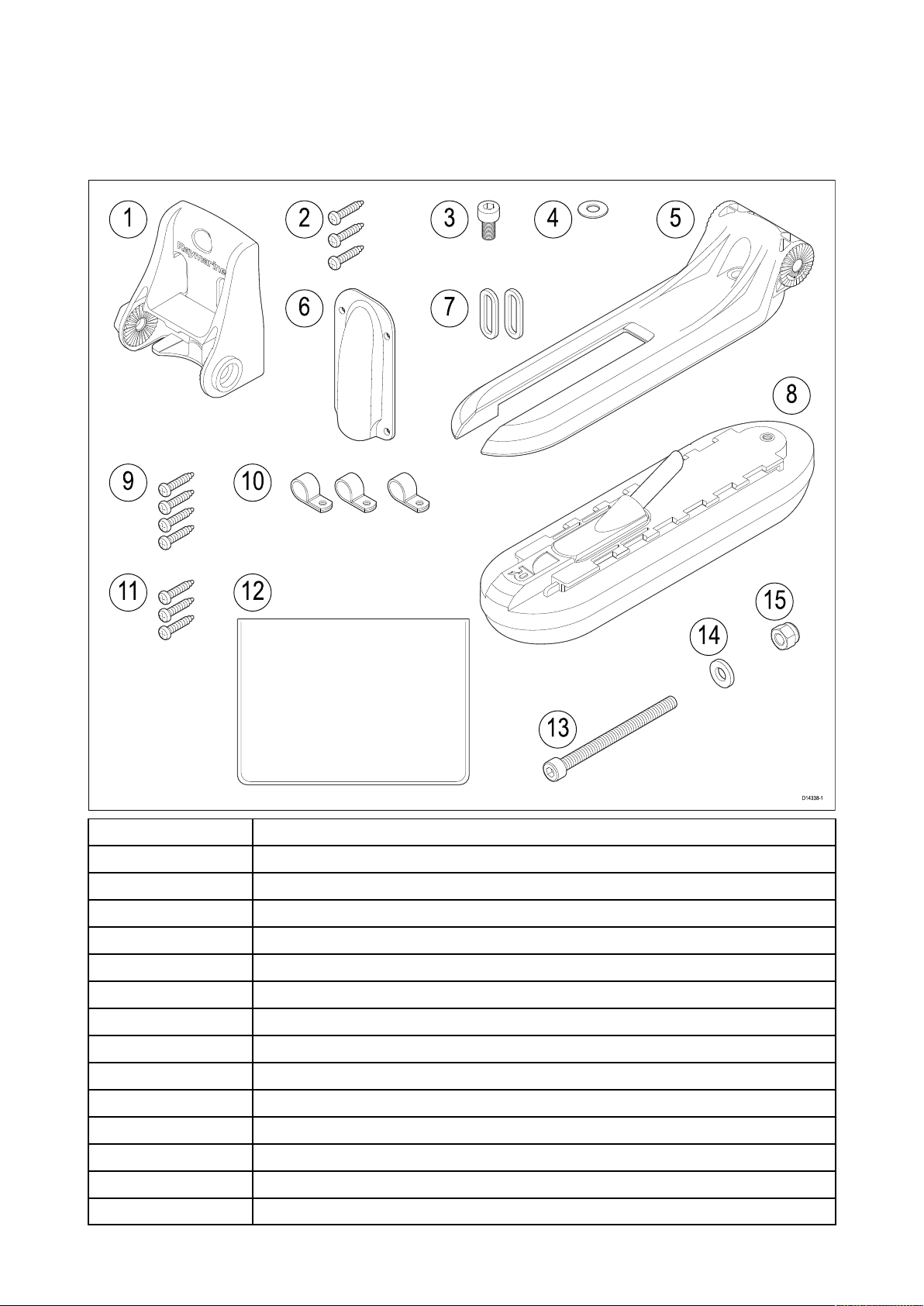
2.5P
Thefollowingpartsaresuppliedwithyourproduct:
Unpackyourproductcarefullytopreventdamageorlossofparts.Checktheboxcontentsagainst
thelistbelow.Retainthepackaginganddocumentationforfuturereference.
artssupplied
1T ransombracket
2
3
4
5Hangerbrack et
6
7
8
9
103xcableclips
11
12
13
14
15
14
3xbrack etfixingscrews(4.2x19mmA4stainlesssteel)
M5 x10hexbolt(A4stainlesssteel)
M5washer(A4stainlesssteel)
Escutcheonplate(usedwhenroutingcablethroughtransomorabulkhead)
2xadjustmentslotwashers
T ransducerwith6m(19.69ft)fittedcable
4xescutcheonplatefixings(#8x13SUS316)
3xcableclipfixings(#8x13SUS316)
Documentationpack
M6 x70hexbolt(A4stainlesssteel)
M6washer(A4stainlesssteel)
M6lockingnut
Page 15

Chapter3:Installation
Chaptercontents
•3.
•3.2Pre-installationtestonpage18
•3.3Selectingalocationonpage19
•3.4Mountingonpage22
1T oolsrequiredonpage16
Installation15
Page 16

1T oolsrequired
3.
Thefollowingtoolsarerequiredtoinstallyourtransducer:
1.P owerdrill
2.4mmhexwrench(Allenkey)
3.5mmhexwrench(Allenkey)
4.Pozi-drivescrewdriver
5.Drillbit(suitableforpilotholes)
6.Marinegradesealant
7.24mm(15/16in)orsuitablesizeholecutter(onlyrequiredwhenroutingthecablethrougha
bulkheadortransom)
8.Masking/adhesivetape
Warning:Marine-gradesealant
Onlyusemarine-gradeneutralcurepolyurethanesealants.DoNOTusesealants
containingacetateorsilicone,whichcancausedamagetoplasticparts.
16
Page 17

Anti-fouling
Wherelocalregulationsallow
,itisrecommendedthatyoucoatyourtransducerusingawater-based
anti-foulingpaint.Thiswillhelppreventthebuild-upoforganicgrowth,whichcanreducetransducer
performance.
Important:
•Beforeapplyingwater-basedanti-foulingpaint,checkthatlocalenvironmentalrulesand
regulationsdonotprohibittheuseofanti-foulingpaint.
•Neverusecopper-basedanti-foulingpaintasthiscanimpacttransducerperformance
•Neverusekeytone-basedanti-foulingpaintasthiscanattackthetransducer’splastic,damaging
thetransducer .
•Paintyourtransducerusingabrush,donotuseaspraycanoraspongerollerasthesemethods
cancausetinyairbubblestobeincorporatedinthepaint,whichwillalsoreducetransducer
performance.
.
Theanti-foulingpaintshouldbeappliedinathinandevencoatcoveringalle xternallyexposed
transducersurfaces.
Y oushouldcleanyourtransducerregularlyandre-applyanti-foulingpaintevery6months,orsooner
dependingonhowrapidlyorganicgrowthbuildsup.
Referto6.2Transducercleaningforcleaningguidance.
Forinstructionsonre-applyinganti-foulingpaint,referto6.3Re-applyinganti-foulingpaint
Installation
17
Page 18

3.2Pre-installationtest
estingthetransducer
T
Transduceroperationshouldbecheckedbeforeinstallation.
1.ConnectthetransducertothetransducerconnectionofaHyperVision™compatibledisplay
(e.g.ElementHV9display).
2.Fullysubmergethetransducerinwater .
3.PowerupyourHyperVision™display.
Thefirsttimethedisplayispoweredup,orafterafactoryresethasbeenperformed,thestartup
wizardisdisplayed.T ransducerselectionispartoftheboatdetailsoptionsinthestartupwizard.
4.OpenaFishfinder(Sonar)apponyourdisplay .
5.Ifrequired,selecttherelevanttransducerfromtheTransducersettingstab( Menu>Transducer
>Transducer).
6.Checkthataccuratedepthandtemperaturereadingsaredisplayed.
7.IfyouexperiencedifficultiesobtainingreadingsthencontactRaymarineT echnicalSupport.
Warning:Transduceroperation
Onlytestandoperatethetransducerinthewater.DoNOToperateoutofwater
asoverheatingmayoccur.
Caution:Transducercable
•DoNOTusethetransducercabletoliftorsuspendthetransducer;always
supportthetransducerbodydirectlyduringinstallation.
•DoNOTcut,shorten,orsplicethetransducercable.
•DoNOTremovetheconnector.
Ifthecableiscut,itcannotberepaired.Cuttingthecablewillalsovoidthe
warranty.
18
Page 19

3.3Selectingalocation
arningsandcautions
W
Important:Beforeproceeding,ensurethatyouhavereadandunderstoodthewarningsand
cautionsprovidedintheChapter1Importantinformationsectionofthisdocument.
ocationrequirements
L
Theguidelinesbelowshouldbefollowedwhenselectingalocationforthetransducer.
Note:
Thetransducerisnotsuitableformountingonvesselswherethetransomisaftofthepropeller(s).
Forbestperformancethetransducermustbeinstalledinalocationwiththeleastturbulenceand
aeration.Themosteffectivewaytodeterminethisisbycheckingthewaterflowaroundthetransom
whilstunderway .
•Mountclosetothekeel(centerline),inapositionwherethetransducerelementwillbefully
submergedwhenthevesselisplaningandturning.
•Mountasuitabledistancefromthepropeller(s)toavoidwake.
•Mountinalocationwherenoloadwillbeappliedtothetransducerduringlaunching,lifting,
traileringandstorageoftheboat.
•Forclockwiserotatingpropellers,mountthetransduceronthestarboardside ,for
counter-clockwise,mountontheportside.
•Onatwinenginevesselmountthetransducerbetweentheengines.
•Turbulencecanbecausedbyanumberofotherfactorssuchassteps(1),ribs(2),rowsofrivets(3)
andstrakes(4).Theturbulenceappearsaftoftheselocations.
Installation19
Page 20

•Airtrappedunderthefrontofthevesselcantravelunderthehullandappearasaerationaft.
Note:
Optimumtransducerlocationwillvarydependingonvesseltype
angleshouldbeobtainedbytestingthetransducerwiththevesselinthewater.
.Optimumtransducerheightand
EMCinstallationguidelines
aymarineequipmentandaccessoriesconformtotheappropriateElectromagneticCompatibility
R
(EMC)regulations,tominimizeelectromagneticinterferencebetweenequipmentandminimizethe
effectsuchinterferencecouldhaveontheperformanceofyoursystem
CorrectinstallationisrequiredtoensurethatEMCperformanceisnotcompromised.
Note:Inareasofe xtremeEMCinterference,someslightinterferencemaybenoticedonthe
product.Wherethisoccurstheproductandthesourceoftheinterferenceshouldbeseparated
byagreaterdistance.
ForoptimumEMCperformancewerecommendthatwhereverpossible:
•R aymarineequipmentandcablesconnectedtoitare:
–Atleast1m(3.3ft)fromanyequipmenttransmittingorcablescarryingradiosignalse.g.VHF
radios,cablesandantennas.InthecaseofSSBradios,thedistanceshouldbeincreasedto2
m(6.6ft).
–Morethan2m(6.6ft)fromthepathofaradarbeam.Aradarbeamcannormallybeassumedto
spread20degreesaboveandbelowtheradiatingelement.
•Theproductissuppliedfromaseparatebatteryfromthatusedforenginestart.Thisisimportant
topreventerraticbehavioranddatalosswhichcanoccuriftheenginestartdoesnothavea
separatebattery.
•Raymarinespecifiedcablesareused.
•Cablesarenotcutorextended,unlessdoingsoisdetailedintheinstallationmanual.
Note:
Whereconstraintsontheinstallationpreventanyoftheaboverecommendations,alwaysensure
themaximumpossibleseparationbetweendifferentitemsofelectricalequipment,toprovidethe
bestconditionsforEMCperformancethroughouttheinstallation.
HV-100productdimensions
A
B
C
20
224.99mm(8.86in)
76.00mm(2.99in)
112.69mm(4.44in)
Page 21

ransducercablelength:6m(19.69ft).
T
A
B
C
130 .00mm(5.12in)
84.00mm(3.31in)
22.20mm(0 .87in)
Installation
21
Page 22

3.4Mounting
ransducerassembly
T
FollowthestepsbelowtoassemblethetransducerreadyforattachingtotheT ransombracket.
1.Slidethehangerbracketoverthetopofthetransduceruntilthenotchinthesideofthebracket
hangeralignswiththeunlockedsymbolonthesideofthetransducer .
2.Allowthehangerbrack ettomovedownintotheslotsonthetopofthetransducer.
3.Slidethehangerbrack etintheoppositedirectionfromstep1,sothatthenotchinthesideofthe
brackethangeralignswiththelockedsymbolonthesideofthetransducer .
4.Securethehangerbrack ettothetransducer,usinga4mmHexwrench(Allenkey)andthe
suppliedM5hexboltandwasher.
22
Page 23

Ensuretighteningtorquedoesnotexceed2Nm(1.48ftlb).Overtighteningmaycausedamageto
thetransducer .
Mountingthetransombrack et
Thetransducermustbemountedonthetransomusingthepartsprovided.Thestepsbelowdescribe
theinitialmountingstepsrequiredinordertotestyourtransducer’sperformance.Aftertesting
thetransduceryoumustfinishthemountingusingtheinstructionsinthe
mounting
1.Fixthesuppliedtransducermountingtemplatetotheselectedlocation,usingmaskingor
self-adhesivetape.
section.
Finishingthetransducer
1T ransducermountingtemplate
2
3Mountawayfromthepropeller
2.Ensurethetemplateisparalleltothewaterline .
3.Drill2xpilotholesfortheadjustmentslotscrewsasindicatedonthetemplate.
Note:
T ohelppreventchippingofthemountingsurface,usepainter’stapetomaskthedrillarea.
Important:
DoNO Tdrillthethirdmountingholeatthisstage.
4.Fillthe2holeswithmarinegradesealant.
5.Inserttheadjustmentslotwashersintotheadjustmentslots.
Installation23
W aterline
Page 24

6.Usingapozi-drivescrewdriverandthescrewsprovided,securethetransombrack
theadjustmentslots.
etusing
Note:
Thethirdlockingscrewisnotuseduntilthetransducerhasbeensuccessfullytested.
Mountingthetransducerassembly
Important:
•Onlyperformtheinstallationwithyourvesseloutofthewater .
•DoNOTliftorsuspendthetransducerusingitscable.
•DoNOTovertightenthebolt.Overtighteningmaycausedamagetothetransducer.
1.P ositionthetransducerassemblyinthetransombracket,ensuringthattheratchetgroovesinthe
transombracketarealignedwiththeratchetgroovesinthehangerbracket.
24
Page 25

2.SlidetheM6metalwasherovertheM6he
x(Allen)bolt.
3.SlidethesuppliedM6hex(Allen)boltthroughthetransombrackethole.
4.PlacetheM6lockingnutintothecaptiveareaonthemountingbracketandholdinposition.
5.Usinga5mmHexwrench((Allenkey),tightentheboltontothelockingnut,untilthetransducer
staysinposition,butcanstillbeadjusted(tilted)byhand.
6.Tiltthetransducersothatthebottomfaceofthetransducerwillbeparallelwiththewaterline
andtightenthehexboltuntilthehangerisheldfirmlyinplace.
Thetransducerpositionwillbeadjustedfurtherduringtesting.
Mountingtheescutcheonplate
Yourtransducerissuppliedwithanescutcheonplate.
Ifyouhavechosentoroutethetransducercablethroughthetransomorthroughabulkhead,you
canusethesuppliedescutcheonplatetocovertheholerequiredtoaccommodatethecable.The
plateisdesignedtofitoveraholeupto25mm(1inch)indiameter.
Afteryouhavethreadedthetransducercablethroughtheholeinthetransomorbulkhead,attach
theescutcheonplateasshown,takingcarethatthecableisnottrappedbetweentheescutcheon
plateandthemountingsurface.
Installation25
Page 26

Note:
T oavoidpossibledamagetothetransducercable,useafiletoround-offtheedgesoftheholethat
thecablepassesthrough.
T estingandadjustingthetransducer
Oncetheinitialmountingprocedureshavebeencarriedout,thetransducermustbetestedbefore
lockingthetransducer’sposition.
Thetestingshouldbecarriedoutwithyourvesselinthewater,withadepthgreaterthan0.7m(2.3
ft)butlessthanthemaximumdepthrangeofthetransducer.
1.OpentheFishfinderapponyourdisplay,andselectthe
Afterafewsecondsthebottomshouldbevisibleonscreenandadepthreadingdisplayed.
2.Startmovingyourvesselatalowspeed,ensuringyouhaveadepthreadingandaclearimageis
displayed.
3.Graduallyincreasethevesselspeedwhilstcheckingthedisplay,iftheimagebecomespooror
thebottomismissingatlowerspeedsthenthetransducerneedstobeadjusted.
4.Angleandheightadjustmentsshouldbemadeinsmallincrementsandre-testedeachtimeuntil
youobtainoptimumperformance.
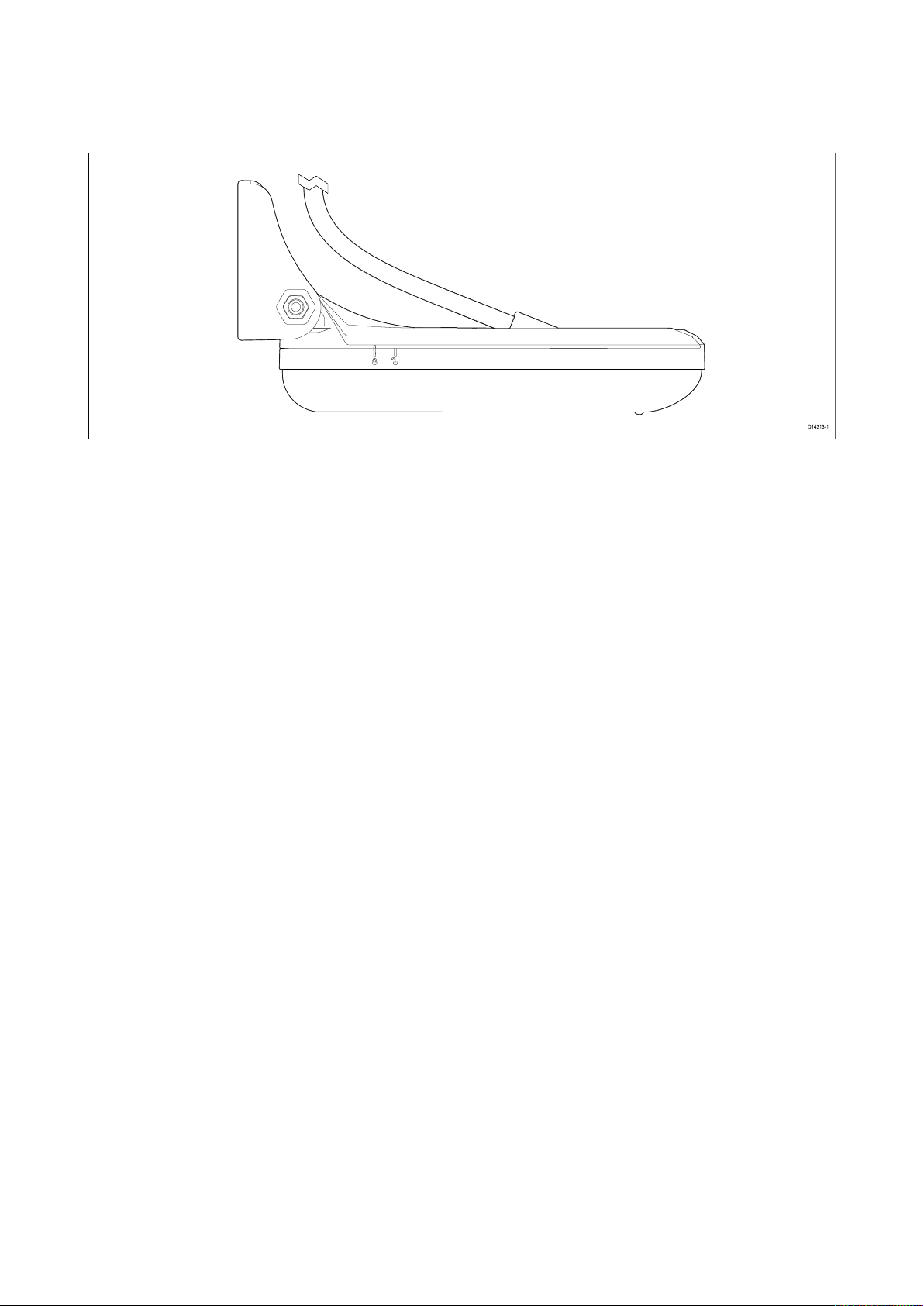
Forbestperformance,youshouldensurethatthebottomhalfofthetransducerassemblyis
positionedsothatitislowerthanthelowestpointofthehullclosesttothetransducer.In
thefollowingillustrations,thedashedlineindicatesthelowestpointofthehullclosesttothe
transducer.
Sonarchannelfromthemenu.
26
Page 27

oosenthemountingbolttoadjustthetransducerangle.
i.L
Angleadjustment
ii.Loosenthe2mountingbracketscrewstoadjustthetransducerheight.
Heightadjustment
iii.Re-tightenthemountingboltandmountingscrewsbeforere-testing.
Note:
•Itmaybenecessarytomak eseveraladjustmentstothetransducerbeforeobtainingoptimum
performance.
•Itmaynotalwaysbepossibletoobtaindepthreadingsathigherspeedsduetoairbubbles
passingunderthetransducer.
•Ifthetransducerrequiresrepositioningensurealloldholesarefilledwithmarinegradesealant.
Installation
27
Page 28

Finalizingthetransducermounting
Onceyouhaveachievedoptimumperformanceatthedesiredvesselspeedsthetransducermustbe
edintopositiontocompletetheinstallation.
lock
1.Drillthelockingholelocationtakingcarenottodamagethetransombrack et.
2.Fillthelockingholewithmarinegradesealant.
3.Lockthetransducerpositionbyfullytighteningall3transombracketmountingscrews.
4.Lockthetransduceranglebytighteningthemountingbolt;donotexceedatorqueof4Nm(2.95
ftlb).Thetransducershouldnotbeeasilymoveablebyhand,andshouldremaininitsnormal
operatingpositionwhenyourvesselisunderway.
Anti-fouling
Wherelocalregulationsallow,itisrecommendedthatyoucoatyourtransducerusingawater-based
anti-foulingpaint.Thiswillhelppreventthebuild-upoforganicgrowth,whichcanreducetransducer
performance.
Important:
•Beforeapplyingwater-basedanti-foulingpaint,checkthatlocalenvironmentalrulesand
regulationsdonotprohibittheuseofanti-foulingpaint.
•Neverusecopper-basedanti-foulingpaintasthiscanimpacttransducerperformance
•Neverusekeytone-basedanti-foulingpaintasthiscanattackthetransducer’splastic,damaging
thetransducer .
•Paintyourtransducerusingabrush,donotuseaspraycanoraspongerollerasthesemethods
cancausetinyairbubblestobeincorporatedinthepaint,whichwillalsoreducetransducer
performance.
.
28
Page 29

Theanti-foulingpaintshouldbeappliedinathinandevencoatcoveringalle xternallyexposed
transducersurfaces.
Y oushouldcleanyourtransducerregularlyandre-applyanti-foulingpaintevery6months,orsooner
dependingonhowrapidlyorganicgrowthbuildsup.
Referto6.2Transducercleaningforcleaningguidance.
Forinstructionsonre-applyinganti-foulingpaint,referto6.3Re-applyinganti-foulingpaint
Installation29
Page 30

30
Page 31

Chapter4:Connections
Chaptercontents
•4.
•4.2Cableroutingonpage33
•4.3Makingconnectionsonpage34
1Generalcablingguidanceonpage32
Connections31
Page 32

1Generalcablingguidance
4.
Cabletypesandlength
Itisimportanttousecablesoftheappropriatetypeandlength
•Unlessotherwisestateduseonlystandardcablesofthecorrecttype,suppliedbyRaymarine.
•Ensurethatanynon-Raymarinecablesareofthecorrectqualityandgauge.Forexample,longer
powercablerunsmayrequirelargerwiregaugestominimizevoltagedropalongtherun.
Strainrelief
Ensureadequatestrainreliefisprovided.Protectconnectorsfromstrainandensuretheywillnotpull
outunderextremeseaconditions.
Cableshielding
Ensurethatallcablesareproperlyshieldedandthatthecableshieldingisundamaged.
Caution:Transducercable
•DoNOTusethetransducercabletoliftorsuspendthetransducer;always
supportthetransducerbodydirectlyduringinstallation.
•DoNOTcut,shorten,orsplicethetransducercable.
•DoNOTremovetheconnector.
Ifthecableiscut,itcannotberepaired.Cuttingthecablewillalsovoidthe
warranty.
32
Page 33

4.2Cablerouting
Cableroutingrequirementsforthetransducercable
Important:
T
oavoidinterference,thecablemustberoutedasfarawayfromVHFradioantennadevices
andcablesaspossible.
•Checkthatthecableislongenoughtoreachthedisplayitwillbeconnectedto
cablesareavailable,ifrequired.
•Ensurethereisenoughslackinthetransducercable,atthetransducerend,toallowthetransducer
topivotupanddownduringadjustment.
•Ifyouintendtoroutethecablethroughthetransomthenyoushouldusethesuppliedescutcheon
platetocoverthehole..
•Securethecableatregularintervalsusingthesuppliedcableclips.
•Anyexcesscableshouldbecoiledupataconvenientlocation.
.
.Optionalextension
HyperVision™transducerextensioncable
Forbestperformance,cablerunsshouldbekepttoaminimum.However,forsomeinstallationsit
maybenecessarytoextendthetransducercable.
A4m(13.12ft)HyperVision™transducerextensioncable(A80562)isavailable
Itisrecommendedthatamaximumofonecableextensionsisused,withthetotalcablelength
notexceeding10m(32.81ft).
Connections33
Page 34

4.3Makingconnections
Followthestepsbelowtoconnectthecable(s)toyourproduct.
1.Ensurethatthevessel'
2.Ensurethatthedevicebeingconnectedtotheunithasbeeninstalledinaccordancewiththe
installationinstructionssuppliedwiththatdevice.
3.Ensuringcorrectorientation,pushthecableconnectorfullyontothecorrespondingconnector
ontheunit.
4.Turnthelockingcollarclockwisetosecurethecable.
spowersupplyisswitchedoff.
34
Page 35

Chapter5:S
ystemchecksandtroubleshooting
Chaptercontents
•5.1Operationinstructionsonpage36
•5.2Troubleshootingonpage37
S ystemchecksandtroubleshooting
35
Page 36

1Operationinstructions
5.
Fordetailedoperationinstructionsforyourproduct,refertothedocumentationthataccompanies
yourdisplay.
AllproductdocumentationisavailabletodownloadfromtheRaymarinewebsite:
www.raymarine.com/manuals.
36
Page 37

5.2T
Thetroubleshootinginformationprovidespossiblecausesandcorrectiveactionrequiredforcommon
problemsassociatedwithinstallationandoperationofyourproduct.
Beforepackingandshipping,allRaymarineproductsaresubjectedtocomprehensivetestingand
qualityassuranceprograms.Ifyoudoexperienceproblemswithyourproductthissectionwillhelp
youtodiagnoseandcorrectproblemsinordertorestorenormaloperation.
Ifafterreferringtothissectionyouarestillhavingproblemswithyourproduct,pleaserefertothe
TechnicalsupportsectionofthismanualforusefullinksandRaymarineProductSupportcontact
details.
roubleshooting
Sonartroubleshooting
Scrollingimageisnotbeingdisplayed
P ossiblecausesPossiblesolutions
Sonardisabled
Incorrecttransducerselected
Damagedcables
Damagedorfouled
transducer
Enable PingfromtheSonarapp’ssoundertab: Menu>Settings
>Sounder>Ping.
CheckthatthecorrecttransducerisselectedintheSonarapp ’s
Transducertab: Menu>Settings>Transducer>Ping.
1.Checkthatthetransducercableconnectorisfullyinsertedand
edinposition.
lock
2.Checkthepowersupplycableandconnectorsforsignsof
damageorcorrosion,replaceifnecessary.
3.Withtheunitturnedon,tryflexingthecableneartothedisplay
connectortoseeifthiscausestheunittore-boot/loosepower,
replaceifnecessary.
4.Checkthevessel’sbatteryvoltage,theconditionofthebattery
terminalsandpowersupplycables,ensuringconnectionsare
secure,cleanandfreefromcorrosion,replaceifnecessary.
5.Withtheproductunderload,usingamulti-meter,checkforhigh
voltagedropacrossallconnectors/fusesetc(thiscancausethe
Fishfinderapplicationstostopscrollingortheunittoreset/turn
off),replaceifnecessary.
Checktransducercondition,ensuringitisnotdamagedandisfree
fromdebris/fouling.Ifnecessary ,cleanorreplaceyourtransducer.
Aftercleaningorreplacementcoatthetransducerusinga
water-basedanti-foulingpaint.
W rongtransducerfittedCheckproductandtransducerdocumentationandensurethatthe
transduceriscompatiblewithyoursystem.
Externalsonarmodule:
Sea T alkhs/RayNetnetwork
problem.
Externalsonarmodule:
Softwaremismatchbetween
equipmentmayprevent
communication.
Nodepthreading/lostbottomlock
P ossiblecausesPossiblesolutions
T ransducerlocation
T ransducerangle
T ransducerkicked-up
S ystemchecksandtroubleshooting
•CheckthattheunitiscorrectlyconnectedtotheDisplayor
networkswitch.Checkallconnectionsensuringconnectionsare
secure,cleanandfreefromcorrosion,replaceifnecessary.
EnsureallR aymarineproductscontainthelatestavailablesoftware,
checktheRaymarinewebsite:www.raymarine.com/softwarefor
softwarecompatibility.
Checkthatthetransducerhasbeeninstalledinaccordancewith
theinstructionsprovidedwiththetransducer.
Ifthetransducerangleistoogreatthebeamcanmissthebottom,
adjusttransducerangleandrecheck.
Ifthetransducerhasakick-upmechanism,checkthatithasnot
kickedupduetohittinganobject.
37
Page 38

P
ossiblecausesPossiblesolutions
owersourceinsufficient
P
Damagedorfouled
transducer
Damagedcables
Withtheproductunderload,usingamulti-meter,checkthe
powersupplyvoltageasclosetotheunitaspossibletoestablish
actualvoltagewhenthecurrentisflowing.(Checkyourproduct’s
Technicalspecificationforpowersupplyrequirements.)
Checktransducercondition,ensuringitisnotdamagedandisfree
fromdebris/fouling.Ifnecessary
,cleanorreplaceyourtransducer.
Aftercleaningorreplacementcoatthetransducerusinga
water-basedanti-foulingpaint.
1.Checktheunit’ sconnectorforbrokenorbentpins.
2.Checkthatthecableconnectorisfullyinsertedintotheunit
andthatthelockingcollarisinthelockedposition.
3.Checkthecableandconnectorsforsignsofdamageor
corrosion,replaceifnecessary.
4.Withtheunitturnedon,tryflexingthepowercableneartothe
displayconnectortoseeifthiscausestheunittore-boot/loose
power,replaceifnecessary.
5.Checkthevessel’sbatteryvoltage,theconditionofthebattery
terminalsandpowersupplycables,ensuringconnectionsare
secure,cleanandfreefromcorrosion,replaceifnecessary.
6.Withtheproductunderload,usingamulti-meter,checkforhigh
voltagedropacrossallconnectors/fusesetc(thiscancausethe
Fishfinderapplicationstostopscrollingortheunittoreset/turn
off),replaceifnecessary.
V esselspeedtoohigh
Bottomtooshallowortoo
deep
Slowvesselspeedandrecheck.
Thebottomdepthmaybeoutsideofthetransducersdepthrange ,
movevesseltoshallowerordeeperwatersasrelevantandrecheck.
P oor/problematicimage
P ossiblecausesPossiblesolutions
T argetswillappeardifferently
ifyourvesselisstationary(e.g.:
fishwillappearonthedisplayas
straightlines).
Scrollingpausedorspeedsettoo
low
Sensitivitysettingsmaybe
inappropriateforpresent
conditions.
Damagedcables
Increasevesselspeed.
Unpauseorincreasesonarscrollingspeed.
CheckandadjustsensitivitysettingsorperformaSonarreset.
1.Checktheunit’ sconnectorforbrokenorbentpins.
2.Checkthatthecableconnectorisfullyinsertedintothe
unitandthatthelockingcollarisinthelockedposition.
3.Checkthecableandconnectorsforsignsofdamageor
corrosion,replaceifnecessary.
4.Withtheunitturnedon,tryflexingthepowercablenear
tothedisplayconnectortoseeifthiscausestheunitto
re-boot/loosepower,replaceifnecessary.
5.Checkthevessel’sbatteryvoltage,theconditionofthe
batteryterminalsandpowersupplycables,ensuring
connectionsaresecure,cleanandfreefromcorrosion,
replaceifnecessary.
6.Withtheproductunderload,usingamulti-meter,check
forhighvoltagedropacrossallconnectors/fusesetc(this
38
Page 39

P
ossiblecausesPossiblesolutions
T
ransducerlocation
cancausetheFishfinderapplicationstostopscrollingor
theunittoreset/turnoff),replaceifnecessary.
•Checkthatthetransducerhasbeeninstalledinaccordance
withtheinstructionsprovidedwiththetransducer .
•Ifatransommounttransducerismountedtoohighon
thetransomitmaybeliftingoutofthewater,checkthat
thetransducerfaceisfullysubmergedwhenplaningand
turning.
T ransducerkicked-up
Ifthetransducerhasakick-upmechanism,checkthatithas
notkickedupduetohittinganobject.
DamagedorfouledtransducerChecktransducercondition,ensuringitisnotdamagedandis
freefromdebris/fouling.Ifnecessary ,cleanorreplaceyour
transducer.
Aftercleaningorreplacementcoatthetransducerusinga
water-basedanti-foulingpaint.
Damagedtransducercable
Checkthatthetransducercableandconnectionisfreefrom
damageandthattheconnectionsaresecureandfreefrom
corrosion.
T urbulencearoundthetransducer
Slowvesselspeedandrecheck.
athigherspeedsmayaffect
transducerperformance
Interferencefromanother
transducer
1.T urnoffthetransducercausingtheinterference.
2.Repositionthetransducerssotheyarefartherapart.
UnitpowersupplyfaultCheckthevoltagefromthepowersupply ,ifthisistoolowit
canaffectthetransmittingpoweroftheunit.
R esettingthesonar
Y oucanresetthedisplay’sinternalsonarmoduletoitsfactorydefaultsettingsfollowingthesteps
below.
IntheFishfinderapp:
1.Select
2.Select
Menu.
Settings.
3.SelectSounder.
4.SelectResetsounder.
5.Select
Yestoconfirmor Notoaborttheoperation,asappropriate.
Theinternalsonarmodulewillnowberesettofactorydefaultsettings.
S ystemchecksandtroubleshooting
39
Page 40

40
Page 41

Chapter6:Maintenance
Chaptercontents
•6.
•6.2Transducercleaningonpage43
•6.3Re-applyinganti-foulingpaintonpage44
1Routinechecksonpage42
Maintenance
41
Page 42

1Routinechecks
6.
Thefollowingperiodicchecksshouldbemade:
•Examinecablesforsignsofdamage,suchaschafing,cutsornicks.
•Checkthatthecableconnectorsarefirmlyattachedandthattheirlockingmechanismsare
properlyengaged.
Note:Cablecheck
sshouldbecarriedoutwiththepowersupplyswitchedoff.
Warning:Highvoltage
Thisproductcontainshighvoltage.Adjustmentsrequirespecializedservice
proceduresandtoolsonlyavailabletoqualifiedservicetechnicians.Thereare
nouserserviceablepartsoradjustments.Theoperatorshouldneverremovethe
coverorattempttoservicetheproduct.
42
Page 43

6.2T
Y oumustcleanyourtransducerregularlytoremoveorganicgrowth.Organicgrowthcanbuildup
quicklyonthebottomfaceofyourtransducer;thiscanimpacttransducerperformanceinamatter
ofweeks.
Important:
ransducercleaning
•Whencleaninggrowthfromananti-fouledtransducer
debrisenterthewater ,asthiscanhaveanimpactonaquaticlife.
•Takecarenottoscratchthesurfaceofthetransducerasthiscanimpacttransducerperformance.
•DoNOTuseharshcleaningsolventssuchasacetoneasthiswilldamagethetransducer .
Followtheguidancebelowtocleangrowthfromyourtransducer:
•useasoftclothandamildhouseholdcleaningdetergenttocleanmildgrowthbuildup .
•useascouringpad,suchasagreenScotchBrite™padandamildhouseholdcleaningdetergent
tocleanmoderategrowthbuildup.
•youmayneedtouseafinegradewetanddrypaperandamildhouseholdcleaningdetergentto
cleanseverebuildup.
,takecarenottoletpaintdustandother
Maintenance43
Page 44

6.3R
Ifyouhaveappliedanti-foulingpainttoyourtransducer ,itisimportanttore-applyitatleastevery
6months,tomaintaineffectiveness.
Followtheinstructionsbelowtore-applyanti-foulingpaint.
Important:
e-applyinganti-foulingpaint
•Followingenvironmentalbestpractice
shouldbeperformedusingsuitablewashdownfacilities,whichensurespaintparticlesdonot
enterthewaterandimpactaquaticlife.
•Takecarenottoscratchthetransducerface,asthismayimpacttransducerperformance.
1.R emoveyourvesselfromthewater.
2.Cleanyourtransducer,ensuringallorganicgrowthisremoved.
3.Removeanyflakinganti-foulpaint.
4.Useasoftdryclothtoremoveanyloosebitsofpaint.
5.Re-applyawater-basedanti-foulingpaint.
,preparationandre-applicationoftheanti-foulingpaint
44
Page 45

Chapter7:T
echnicalsupport
Chaptercontents
•7.1Raymarineproductsupportandservicingonpage46
•7.2Learningresourcesonpage48
T echnicalsupport
45
Page 46

.1Raymarineproductsupportandservicing
7
Raymarineprovidesacomprehensiveproductsupportservice,aswellaswarranty,service,and
repairs.Y oucanaccesstheseservicesthroughtheRaymarinewebsite,telephone,ande-mail.
Productinformation
Ifyouneedtorequestserviceorsupport,pleasehavethefollowinginformationtohand:
•Productname.
•Productidentity.
•Serialnumber .
•Softwareapplicationversion.
•Systemdiagrams.
Y oucanobtainthisproductinformationusingdiagnosticpagesoftheconnectedMFD.
Servicingandwarranty
Raymarineoffersdedicatedservicedepartmentsforwarranty,service,andrepairs.
Don’tforgettovisittheRaymarinewebsitetoregisteryourproductforextendedwarrantybenefits:
http://www.raymarine.co.uk/display/?id=788.
R egion
Contact
UnitedKingdom(UK),EMEA,and
AsiaP acific
UnitedS tates(US)
W ebsupport
Pleasevisitthe“Support”areaoftheRaymarinewebsitefor:
•ManualsandDocuments—http://www.raymarine.com/manuals
•FAQ/Knowledgebase—http://www.raymarine.com/knowledgebase
•Technicalsupportforum—http://forum.raymarine.com
•Softwareupdates—http://www.raymarine.com/software
Worldwidesupport
R egion
UnitedKingdom(UK),EMEA,and
AsiaP acific
UnitedS tates(US)
A ustraliaandNewZealand
(Raymarinesubsidiary)
•E-Mail:emea.service@raymarine.com
•Tel:+44(0)1329246932
•E-Mail:rm-usrepair@flir.com
•Tel:+1(603)3247900
Contact
•E-Mail:support.uk@raymarine.com
•Tel:+44(0)1329246777
•E-Mail:support@raymarine.com
•Tel:+1(603)3247900(Toll-free:+8005395539)
•E-Mail:aus.support@raymarine.com
•Tel:+61289770300
France
(R aymarinesubsidiary)
Germany
(R aymarinesubsidiary)
Italy
(R aymarinesubsidiary)
Spain
(A uthorizedRaymarinedistributor)
Netherlands
(R aymarinesubsidiary)
46
•E-Mail:support.fr@raymarine.com
•Tel:+33(0)146497230
•E-Mail:support.de@raymarine.com
•Tel:+49(0)402378080
•E-Mail:support.it@raymarine.com
•Tel:+390299451001
•E-Mail:sat@azimut.es
•Tel:+34962965102
•E-Mail:support.nl@raymarine.com
•Tel:+31(0)263614905
Page 47

R
egion
Contact
weden
S
(Raymarinesubsidiary)
Finland
aymarinesubsidiary)
(R
Norway
aymarinesubsidiary)
(R
Denmark
(R aymarinesubsidiary)
Russia
(A uthorizedRaymarinedistributor)
•E-Mail:support.se@raymarine.com
•Tel:+46(0)317633670
•E-Mail:support.fi@raymarine.com
•Tel:+358(0)207619937
•E-Mail:support.no@raymarine.com
•Tel:+4769264600
•E-Mail:support.dk@raymarine.com
•Tel:+4543716464
•E-Mail:info@mikstmarine.ru
•Tel:+74957880508
T echnicalsupport
47
Page 48

.2Learningresources
7
Raymarinehasproducedarangeoflearningresourcestohelpyougetthemostoutofyourproducts.
Videotutorials
R
aymarineofficialchannelonY ou Tube:
•http://www.youtube.com/user/RaymarineInc
LightHouse™3tipsandtricks:
•http://www.raymarine.com/multifunction-displays/light-
house3/tips-and-tricks
VideoGallery:
•http://www.raymarine.co.uk/view/?id=2679
Note:
•ViewingthevideosrequiresadevicewithanInternetconnection.
•SomevideosareonlyavailableinEnglish.
T rainingcourses
Raymarineregularlyrunsarangeofin-depthtrainingcoursestohelpyoumakethemostofyour
products.VisittheT rainingsectionoftheRaymarinewebsiteformoreinformation:
•http://www.raymarine.co.uk/view/?id=2372
FAQsandKnowledgeBase
RaymarinehasproducedanextensivesetofFAQsandaKnowledgeBasetohelpyoufindmore
informationandtroubleshootanyissues.
•http://www.raymarine.co.uk/knowledgebase/
Technicalsupportforum
Y oucanusetheT echnicalsupportforumtoaskatechnicalquestionaboutaRaymarineproduct
ortofindouthowothercustomersareusingtheirRaymarineequipment.Theresourceisregularly
updatedwithcontributionsfromRaymarinecustomersandstaff:
•http://forum.raymarine.com
48
Page 49

Chapter8:T
echnicalspecification
Chaptercontents
•8.1T echnicalspecificationonpage50
T echnicalspecification
49
Page 50

1Technicalspecification
8.
Physicalspecification
Overalldimensions:
Cablelength:
W eight(unboxed):1.05kg(2.31lb)
ength:224.99mm(8.86in)
•L
•Height:112.69mm(4.44in)
•Width:76.00mm(2.99in)
•HV-100:6m(19
.69ft)fittedcable
Environmentalspecification
Operatingtemperature
S toragetemperature
W aterproofrating
–2ºC(28.4ºF)to+55ºC(131ºF)
–20ºC(23ºF)to+70ºC(158ºF)
•IPx6(surfacesexteriortohull,only)
•IPx7
•IPx8
Hyper Vision™technicalspecification
ThefollowingspecificationonlyappliestoHyperVision™products.
Frequencies
•1.2MHzCHIRP
•350kHzCHIRP
•200kHzCHIRP
Channels•ConicalCHIRPsonar
•R ealVision™3D(Hyper)
•RealVision™3D(Standard)
•SideVision™(Hyper)
•SideVision™(Standard)
•DownVision™(Hyper)
•DownVision™(Standard)
200kHzrange
350kHzrange
1.2MHzrange
•ConicalCHIRPsonar=0 .6M(2ft)to274m(900ft)
•R ealVision™3D=0.6M(2ft)to91m(300ft)
•SideVision™=0.6M(2ft)to91m(300ft)eachside
•DownVision™=0.6M(2ft)to183m(600ft)
•R ealVision™3D=0.6M(2ft)to38m(125ft)
•SideVision™=0.6M(2ft)to38m(125ft)eachside
•DownVision™=0.6M(2ft)to38m(125ft)
Conformancespecification
Conformance•EN60945:2002
50
•IEC28846:1993
•EMCDirective2014/30/EU
•A
ustraliaandNewZealand:C-Tick,ComplianceLevel2
Page 51

Chapter9:Sparesandaccessories
Chaptercontents
.1Sparesonpage52
•9
•9.2Accessoriesonpage53
Sparesandaccessories
51
Page 52

9
.1Spares
DescriptionP
HV-100T
ransombracketR70651
artnumber
52
Page 53

.2Accessories
9
DescriptionP
HV-100trollingmotormountA
Vision™transducerextensioncable4m
Hyper
(13.12ft)
artnumber
80557
A80562
Sparesandaccessories
53
Page 54

Page 55

Inde
x
O
Operationinstructions.......................................10,36
A
Accessories......................................................52–53
Anti-fouling...................................................17,28,44
Assembly.................................................................22
C
Cableextension......................................................33
Cableprotection......................................................32
Cablerouting...........................................................33
Cleaningthetransducer..........................................43
Connections
Generalcablingguidance....................................32
Contactdetails.........................................................46
D
Documentation
Installationinstructions........................................10
Mountingtemplate...............................................10
Operationinstructions...................................10,36
E
ElectromagneticCompatibility................................20
See
EMC,
Escutcheonplate.....................................................25
ElectromagneticCompatibility
P
Productrecycling(WEEE)..........................................8
Productsupport.......................................................46
S
ServiceCenter.........................................................46
Servicing....................................................................7
See
Strainrelief,
Supportforum.........................................................48
Cableprotection
T
Technicalspecification.....................................49–50
TechnicalSpecification
Conformance......................................................50
Environmental.....................................................50
HyperVisionSonar..............................................50
Physical...............................................................50
Technicalsupport..............................................46,48
Trainingcourses......................................................48
Transducermounting..............................................24
Troubleshooting......................................................37
V
F
FAQs........................................................................48
H
HV-100
Compatibledisplays.............................................13
HV-100transducer....................................................11
I
Installation
Testing...........................................................18,26
K
Knowledgebase......................................................48
L
LightHouse™3
TipsandTricks.....................................................48
LightHouseSport
Compatibledisplays.............................................13
Locationrequirements
General................................................................19
VideoGallery...........................................................48
W
Warranty..................................................................46
WEEEDirective..........................................................8
M
Maintenance..............................................................7
Page 56

Page 57

Page 58

Marine House, Cartwright Drive, Fareham, Hampshire.
Raymarine
PO15 5RJ. United Kingdom.
Tel: +44 (0)1329 246 700
www.raymarine.com
a brand by
 Loading...