

Page 1

hsb
2
PLUS Series
CRT Display
Owner’s
Handbook
Document number: 81187_3
Date: September 2002
Page 2

Page 3
Preface iii
hsb
PLUS Series CRT Display Owner’s
Handbook
September 2002
INTENDED USE
Thedisplayunitsdetailedin this handbook may form part ofnavigational
radarsystemsintendedfor light marine use. These displaysandradar
systems are only an aid to navigation.
SAFETY NOTICES
Thisradarequipmentmust be installed and operated in accordance with the
instructionscontainedinthismanual.Failuretodosocan result in personal
injuryand/ornavigationalinaccuracies.In particular:
1.HIGH VOLTAGE.TheCRTdisplayunitandscannerunit contain
highvoltages.Adjustmentsrequirespecializedservice proceduresand
toolsonlyavailabletoqualifiedservicetechnicians–therearenouser
serviceablepartsoradjustments.Theoperatorshouldnever removethe
displayunitcoveror attempt to service the equipment.Ifthesafetyseal
fittedacrossoneof the display cover fixing screws is damaged or missing,
contactaqualifiedservicetechnicianbeforetheequipmentispowered.
2
2.X-RAYS. X-Raysaregeneratedbythisequipment.Theacceleration
voltagemustnotexceed12 kV. No internal access is provided to controls
whichaffectthisvoltage-see note 1 above.
3.ELECTROMAGNETIC ENERGY. Theradar scannertransmits
electromagneticenergy. It is important that the radar is turned off whenever
personnelarerequiredtocomecloseto the scanner to perform work on the
scannerassemblyorassociatedequipment.
Itisrecommendedthatthe radar scanner is mountedoutofrangeofpersonnel
(aboveheadheight).
Avoid lookingdirectlyattheantennaasyoureyesarethemostsensitivepartof
thebodyto electromagneticenergy.
Whenproperlyinstalled andoperated,theuse of thisradarwillconformto the
requirementsofANSI/IEEEC95.1-1992StandardforSafetyLevelswith
RespecttoHumanExposuretoRadioFrequencyElectromagneticFields,3Hz
to300GHzandNRPB, Board StatementonRestrictionson HumanExposure
toStati candTimeVarying ElectromagneticFieldsandRadiation.DocNRPB,
N0.5 (1993).
4.NAVIGATIONAID.Thisunit isonlyanaidtonavigation.Itsaccuracycan
beaffectedbymanyfactors,includingequipmentfailureordefects,
Page 4

iv hsb
environmentalconditions,andimproperhandlingoruse.Itisthe user’s
responsibilitytoexercisecommonprudenceandnavigationaljudgements.
Thisradarunitshouldnotberelieduponasasubstitut efor such prudence and
judgement.
5.FUSES.Forcontinuedprotection againstriskoffire,replacefuses withthe
correcttypeandrating,asspecifiedinAppendix A.
6.DISPOSAL INSTRUCTIONS. Donotburn the CRTDisplayunit.It
containsberylliumcopperandplasticswhichproducetoxicfumes.Itis also
possiblefortheCRTtube toimplode.
Raymarineproductsaresupportedbya network of Authorized Service
Representatives.Forinformationonourproductsandservices,contacteither
ofthe following:
UNITEDSTATES RaymarineInc.
22 Cotton Road, Unit D
Nashua,NH 03063-4219
Telephone: +1603 881 5200
+1800 539 5539
Fax: +1603 864 4756
2
PLUS Series CRT Display
EUROPE RaymarineLimited
AnchoragePark
Portsmouth
Hampshire PO3 5TD
England
Telephone: +44(0) 23 9269 3611
Fax: +44(0)23 9269 4642
Copyright© Raymarine Ltd.2002
Thetechnicalandgraphicalinformationcontainedinthishandbook,to the
bestofourknowledge,wascorrectasitwenttopress.However,ourpolicyof
continuousimprovementandupdatingmay change product specifications
withoutpriornotice. As aresult,unavoidabledifferencesbetweentheproduct
andhandbookmay occur from time to time, for whichliabilitycannotbe
acceptedbyRaymarine.
Raymarineisa registeredtrademarkofRaymarineLimited.
SeaTalk is aregisteredtrademarkofRaymarineLimited.
2
hsb
isa trademarkof RaymarineLimited.
Pathfinder Plus is a trademark of Raymarine Limited.
ThisproductcontainstechnologyprovidedunderlicensebyAcornGroupplc.
ThecopyrightofthisintellectualpropertyisacknowledgedbyRaymarine
Ltd.,asareAcorn’strademarksand patents. Acorn’sworldwideweb address
is http://www.acorn.com.
Page 5

Preface v
Preface
Thishandbookdescribestheradarandchart aspectsof the following hsb
2
(PLUS)seriesdisplaysystemsfromRaymarine:
System Display Scanner Chartplotter
Pathfinder Radar R70 PLUS,
R80 PLUS
Combined Pathfinder Radar/Chartplotter R70RC PLUS
R80RCPLUS
Yes N o
Yes Yes
Thishandbookalsodescribestheuse of multi-displaysystems.
Note:Radar systems are supplied with an appropriate Raymarine scanner
unitandinter-connectingcable.Detailsforinstallingthescanneraredescribedinthe PathfinderRadar Scanner Owner’s Handbook.
TheRaychart(RC)display units include a cartridge holder assembly which
containstwoslotsforC-MAP NT chart cards.
Thishandbookcontainsveryimportantinformationontheinstallationand
operationofyournew equipment.In order to obtain the best results in
operationandperformance,pleasereadthishandbookthoroughly.
Raymarine’s TechnicalServicesrepresentativesor yourlocaldealerwillbe
availabletoanswerany questionsyou may have.
Warranty
To registeryourdisplayunitownership,pleasetakeafew minutes to fill out
thewarrantyregistrationcardfoundattheendof this handbook. It is very
importantthatyoucompletetheownerinformationandreturnthecardto the
factoryinordertoreceivefullwarrantybenefits.
EMC Conformance
AllRaymarineequipmentandaccessoriesaredesignedtothebestindustry
standardsforusein the recreationalmarineenvironment.
Thedesignand manufacture of Raymarine equipment and accessories
conformtotheappropriateElectromagneticCompatibil ity(EMC) standards,
butcorrectinstallationisrequiredtoensurethatperformanceisnot
compromised.
Page 6

vi hsb
2
PLUS Series CRT Display
Contents
Preface ............................................................................................... v
Warranty ...........................................................................................v
EMC Conformance ...........................................................................v
Chapter 1: Overview ..........................................................................................1.1
How to Use This Handbook .......................................................... 1.1
1.1 General .......................................................................................... 1.4
Introductiontohsb2 Systems ........................................................ 1.4
PLUS Display Units ..................................................................... 1.5
OperatingModes .......................................................................... 1.6
Headingand Position Data ........................................................... 1.9
1.2 The Pathfinder Radar PLUS Display .......................................... 1.10
PathfinderRadarPLUS Display Options ................................... 1.10
Radar Functions ......................................................................... 1.12
1.3 The Chartplotter Display ..................................................... .......1.13
ChartplotterDisplayOptions ...................................................... 1.14
ChartplotterFunctions ................................................................ 1.15
1.4 Operating Controls .....................................................................1.16
TrackballandCursor................................................................... 1.16
DedicatedKeys ........................................................................... 1.18
RotaryControls and On-Screen Sliders ...................................... 1.19
SoftKeys ..................................................................................... 1.19
Pop-Up Menus ............................................................................ 1.20
DatabaseLists ............................................................................. 1.21
Chapter 2: Getting Started & Adjusting the Display ....................................2.1
2.1 Introduction ..................................................................................2.1
ConventionsUsed ......................................................................... 2.1
Simulator ...................................................................................... 2.1
2.2 Switching the Display Onand Off ................................................ 2.2
SimulatorMode ............................................................................ 2.5
Lighting,BrillianceandContrast .................................................2.5
2.3 Controlling the Display ................................................................. 2.7
SelectingtheMode of Operation .................................................. 2.7
Page 7

Preface vii
CustomizingtheScreen PresentationOptions ............................ 2.13
2.4 Radar Display Control Functions ............................................... 2.16
Using the Zoom Function ........................................................... 2.16
OffsettingtheCenter ................................................................... 2.17
Hidingthe Ship’sHeadingMarker(SHM) ................................. 2.18
2.5 Chart Display Control Functions ................................................ 2.19
MovingAround the Chart ........................................................... 2.19
2.6 TypicalChartScenarios .............................................................. 2.23
Placeand Goto a Waypoint ......................................................... 2.24
Makeand Follow a Route ........................................................... 2.26
ReviewYour Passage Plan .......................................................... 2.28
ReviewYour Passage Plan .......................................................... 2.29
DisplayingtheRadarand SynchronizingRadar & Chart ........... 2.30
Chapter 3: Standard Radar Operations ..........................................................3.1
3.1 Introduction ..................................................................................3.1
3.2 Range Control ............................................................................... 3.2
Changingthe Range ...................................................................... 3.3
DeterminingActualRadar Range ................................................. 3.3
3.3 Interpreting and Adjusting the RadarPicture ............................... 3.4
IdentifyingFalseEchoReturns .................................................... 3.5
AdjustingGain,Sea Clutter,RainClutterandTune ..................... 3.7
Changingthe Targets Display ......................................................3.11
3.4 Measuring Range and BearingUsing VRM/EBLs .................... 3.13
MeasuringRange and Bearing to TargetfromVessel ................. 3.14
MeasuringRange and Bearing Between Targets(FLOAT)........ 3.16
ControllingVRM/EBL Data Boxes ...........................................3.18
3.5 Setting Guard Zones andAlarms ................................................ 3.19
Placinga Guard Zone .................................................................. 3.20
Moving,Reshaping or Deleting a Guard Zone ........................... 3.21
ControllingGuardZone Alarms ................................................. 3.21
3.6 MARPA ............................................................................... .......3.23
IntroductiontoMARPA ............................................................. 3.23
Using MARP A............................................................................ 3.25
Page 8

viii hsb
2
PLUS Series CRT Display
Chapter 4: Integrated Radar Operations ........................................................4.1
4.1 Introduction ..................................................................................4.1
4.2 Changing the HeadingMode ........................................................ 4.2
TrueandRelativeMotion ............................................................. 4.2
4.3 Using Marks .................................................................................. 4.4
4.4 Man Overboard(MOB) ................................................................ 4.5
4.5 Cursor Echo .................................................................................. 4.6
Chapter 5: Standard Chart Operations ...........................................................5.1
5.1 Introduction ..................................................................................5.1
5.2 Using Chart Cards ......................................................................... 5.2
Insertinga Chart Card ...................................................................5.2
Removing a Chart Card ................................................................ 5.3
DisplayingtheChart Data ............................................................. 5.3
DisplayingChartObjectand Source Information ........................ 5.4
5.3 WorkingwithWaypoints .............................................................. 5.8
Introduction .................................................................................. 5.8
Placinga Wayp oint ....................................................................... 5.9
SelectingaW aypoint .................................................................. 5.12
Waypoint DataDisplay ............................................................... 5.12
Editingthe WaypointDetails ...................................................... 5.13
Erasinga Waypo int ..................................................................... 5.14
Movinga Waypoint .................................................................... 5.14
Using the ST60 or ST80 NavigatorKeypad ............................... 5.15
5.4 WorkingwithRoutes ..................................................................5.18
Creatinga New Route .................................................................5.19
Savingthe Current Route ............................................................ 5.22
ClearingtheCurrent Route .........................................................5.23
Retrievea Route From the Database........................................... 5.23
DisplayingRouteInformation .................................................... 5.24
Usingthe Route List to EraseandName a Route ....................... 5.26
Editing a Route ...........................................................................5.27
5.5 Following Routes and Goingto Points ....................................... 5.29
Followa Route ............................................................................ 5.29
Target Point Arrival .................................................................... 5.31
Page 9

Preface ix
OtherFollow Route Options ....................................................... 5.31
Going ToanIndividualTarget Point ........................................... 5.32
StopFollowor Stop Goto ............................................................ 5.33
5.6 TransferringWaypoints and Routes ...........................................5.34
5.7 Using Tracks ...............................................................................5.38
SettingUp a Track ...................................................................... 5.39
ClearingtheCurrent Track ......................................................... 5.40
ManagingTracks ........................................................................5.40
SmartRoute ................................................................................. 5.42
Chapter 6: Further Chart Operations ..............................................................6.1
6.1 Introduction ..................................................................................6.1
6.2 Measuring Distances Using the VRM/EBLKey .......................... 6.2
6.3 Alarms and Timers........................................................................ 6.4
Alarm Reporting ........................................................................... 6.4
SettingAlarms and Timers ........................................................... 6.5
6.4 Man Overboard(MOB) ................................................................ 6.6
6.5 Cursor Echo .................................................................................. 6.7
6.6 GPS Setup ..................................................................................... 6.8
6.7 Data Log Mode ...........................................................................6.10
Chapter 7: Setting Up the System Defaults ...................................................7.1
7.1 Introduction ..................................................................................7.1
7.2 Changing the SetUp Parameters .................................................. 7.2
7.3 System Set Up Parameters ............................................................ 7.4
Data Boxes .................................................................................... 7.6
BearingMode ............................................................................... 7.6
CursorReference .......................................................................... 7.6
CursorReadout .............................................................................7.6
Help............................................................................................... 7.7
SoftKeys ....................................................................................... 7.7
KeyBeep ...................................................................................... 7.7
MOB Data ..................................................................................... 7.7
AutopilotPop Up .......................................................................... 7.7
MenuTimeoutPeriod ...................................................................7.7
Page 10

x hsb
Units .............................................................................................. 7.7
Variation Source ........................................................................... 7.8
BridgeNMEA Heading ................................................................7.8
NMEA Out Set Up ........................................................................ 7.9
CursorEcho .................................................................................. 7.9
Date and TimeSettings .................................................................7.9
GPS SOG/COG Filter ................................................................. 7.10
CompassSet Up .......................................................................... 7.10
Language .................................................................................... 7.10
Simulator .................................................................................... 7.10
7.4 Radar Set UpParameters .............................................................7.11
EBL Display ................................................................................7.11
TimedTrans missi onOption .......................................................7.12
MarksOptions ............................................................................ 7.12
CustomScale .............................................................................. 7.12
BearingAlignment ..................................................................... 7.13
AntennaSize ............................................................................... 7.13
Sendon HSB ............................................................................... 7.13
2
PLUS Series CRT Display
7.5 MARPASetUpParameters ........................................................ 7.14
7.6 Advanced Settings ...................................................................... 7.15
DisplayTiming ...........................................................................7.15
STC Preset .................................................................................. 7.16
TunePreset..................................................................................7.16
7.7 Chart Set UpParameters ............................................................. 7.17
CustomizeChart ......................................................................... 7.17
PlotterMode ............................................................................... 7.18
ChartOrientation ........................................................................7.18
ObjectInformation ..................................................................... 7.19
Waypoint Options ....................................................................... 7.19
Vectors ........................................................................................ 7.19
Radar/ChartSynch ...................................................................... 7.19
DatumSelection ......................................................................... 7.19
PositionOffset ............................................................................ 7.20
Page 11

Preface xi
Chapter 8: Installation ......................................................................................8.1
8.1 Introduction ..................................................................................8.1
Planningthe Installation ............................................................... 8.2
EMC Installation Guidelines ........................................................ 8.2
8.2 Unpacking and Inspecting theComponents ................................. 8.4
8.3 Selecting the Display Unit Location .............................................8.5
8.4 Cable Runs .................................................................................... 8.8
PowerCable .................................................................................. 8.8
Inter-UnitScannerCable .............................................................. 8.9
2
hsb
Cable ..................................................................................... 8.9
8.5 Mounting the DisplayUnit ......................................................... 8.10
8.6 System Connections ................................................................... 8.12
DisplayUnit Connection ............................................................ 8.13
8.7 Radar System TestsandInstallationAlignment ......................... 8.16
SystemCheck ............................................................................. 8.16
SwitchOn and Initial Setup ........................................................8.16
RadarSystem Checks and Adjustments ..................................... 8.17
EMC Conformance ..................................................................... 8.20
8.8 Integrated Systems ...................................................................... 8.21
2
hsb
™(High Speed Bus) Multiple Display Systems .................. 8.21
SeaTalk® andNMEA In ............................................................. 8.24
Usingthe SeaTalkAuxiliaryJunctionBox................................. 8.29
Data Output .................................................................................8.30
Data Conversion ......................................................................... 8.30
8.9 Integrated System Checks .......................................................... 8.31
ChartDisplay- R70RC PLUS, R80RC PLUS ........................... 8.31
ReceivedData ............................................................................. 8.31
TransmittedData ........................................................................ 8.31
Chapter 9: Maintenance and Problem Solving ..............................................9.1
9.1 Maintenance .................................................................................9.1
RoutineChecks ............................................................................. 9.1
EMC Servicing and Safety Guidelines ......................................... 9.1
Page 12

xii hsb
2
PLUS Series CRT Display
9.2 Resetting the System ..................................................................... 9.2
9.3 Problem Solving ........................................................................... 9.3
Technical Support: ........................................................................ 9.3
How to Contact Raymarine (US) .................................................. 9.4
How to Contact Raymarine (Europe) ...........................................9.5
Worldwide Support ....................................................................... 9.5
Appendix A: Specification ...................................................................................A.1
2
hsb
Series7"and 10" CRTDisplays .............................................A.1
Appendix B: Using the Auxiliary Junction Box ................................................. B.1
Raystar112,105,Apelco182and 182XT ....................................B.2
AutohelmGPS, Z260 and Z273 ...................................................B.3
Raystar112LP(SeaTalk version) .................................................B.4
Raystar114CombinedGPSandDifferentialBeaconReceiver ...B.5
Raystar120 WAAS Satellite Differential Receiver ......................B.6
Appendix C: C-MAP Chart Card Features .......................................................... C.1
Appendix D: SeaTalk and NMEA Data Received and Transmitted ................ D.1
Appendix E: Connecting a Raymarine Heading Sensor ...................................E.1
G-SeriesCourseComputer ...........................................................E.1
Appendix F: Abbreviations ..................................................................................F.1
Index ................................................................................................xiii
Page 13

Chapter 1: 1-1
Chapter 1:
1.1 Overview
How to Use This Handbook
Thishandbookdescr ibesthefollowinghsb2(PLUS)seriesdisplays andmultidisplaysystems:
R70PLUS Pathfinder Radar,7"CR TDisplay
R70RCPLUS Pathfinder Radar & Chartplotter,7"CR TDisplay
R80PLUS Pathfinder Radar,10"CRTDisplay
R80RCPLUS Pathfinder Radar & Chartplotter,10"CR TDisplay
Ifyouare installingthe displaysystem yourself,youshouldread Chapter 8
beforeyoustarttheinstallation.Thischapteralsoprovidesinformationthat
willbeuseful if you are connecting your
equipment.
2
hsb
Foranoverviewof
(PLUS)displaysystems ,thedisplayunitcontrols and
the radar/chartplotter system, read Chapter 1.1. Chapter 2 will help you start
usingyoursystem.
2
hsb
series system to other
Overview
Overview
FordetailedinformationonradaroperationsrefertoChapter3:Standard
RadarOperationsandChapter 4:IntegratedRadar Operations.
Forchartplotteroperatingdetails,refertoChapter 5 andChapter 6.
To changethesystemsetup defaults, read Chapter 7.
Detailsforinstallingaradarscannerareprovidedinthe Pathfinder Radar
ScannerOwner’s Handbook suppliedwithyourscanner.
Note:Many illustrationsinthishandbookshowexamplescreens.The screen
youseeon your display depends on your system configuration and set up options,soitmay differ from the illustration.
Thishandbookisorganizedasfollows:
2
hsb
Chapter 1.1providesanoverviewof an
featuresandfunctions ofthe
2
hsb
PLUSseriesCRT Display.Thischapteralso
multi-display system and the
providesanoverviewofthe controls.You should read this chapter to
familiarizeyourselfwiththesystem.
Chapter 2explainshow to start using the display and describes how to use
someofthebasicradarandchart functions.Chapter2alsoprovidesoperating
guidelinesfortypicalchartplotterscenarios;theseguidelinesintroduceyou to
manyof the chartplotterfunctions.
Page 14

1-2 hsb
2
PLUS Series CRT Display
How to Use This
How to Use This
Handbook
Handbook
Chapter 3providesdetailedoperatinginformationforthemainradar
functions-adjustingtheradarpicture;measuringdistancesandbearings;
settingguardzonesandalarms;usingMARPA fortargettracking.
Chapter 4providesdetailedoperatinginformationforintegratedradarsystem
functions,includingusingmarks,manoverboardandcursorecho.
Chapter 5providesdetailedoperatinginformationforthestandard
chartplotterfunctions- usingchartcards,plottingwaypointsandroutes,
followingroutesandshowingtracks.
Chapter 6providesdetailedoperatinginformationforfurtherchartfunctions,
includingmeasuringdistances,manoverboardandcursorecho.Itincludes
instructionsforsettingupadifferentialGPS.
Chapter 7providesinstructionsforsettingupyoursystemto suit your
preferences.Youshouldreadthischaptertodeterminehowtosetuptheradar
andchartplottersystemdefaults.
Chapter 8providesplanningconsiderationsanddetailedinstructionsfor
installingthedisplayunit(s).Itshouldbereferredtowhenyouare ready to
installthesystem.Detailstoconnectthedisplaytoother equipment are also
provided.To installacompleteradarsystem,you will also need to read the
Owner’sHandbooksuppliedwiththescanner.
Chapter 9providesinformationonuser maintenance,and what to do if you
experienceproblems.
TheAppendicesprovideadditionalinformationthatyoumayfinduseful:
Appendix Aliststhetechnicalspecificationsfortheradarandchartplotter.
Appendix BprovidesdetailsonconnectingthedisplayunittospecificGPS
systems.
Appendix Cdefinesthechartfeaturesshown on the chart display.
Appendix Ddefines the SeaTalk and NMEA data that is transferred on
integratedsystems.
Appendix EprovidesdetailsonconnectingaRaymarineheadingsensorfor
MARPA.
Appendix Fprovidesalistof abbreviations.
AnIndexand warranty information are included at the end of thehandbook.
Asummaryof the radar and chartplotter controls are provided on the Quick
ReferenceCardssuppliedwithyoursystem.
Page 15

Chapter 1: 1-3
Terminology
Thefollowingterminologyisusedto describe radar and chartplottersystems:
Master A unit capable of sourcing specificdata such as
fishfinder ,chart or radar data.
Repeater A unit capable of displaying data, such as radar,from
2
hsb
.
FishfinderDisplayUnitprovidingFishfinder Master,ChartRepeaterand
RadarRepeaterfunctionality.
RadarDisplay UnitprovidingRadar Master, FishfinderRepeater
andChart Repeaterfunctionality.
ChartDisplay UnitprovidingChartMaster,Fishfinder Repeater and
RadarRepeaterfunctionality.
CombinedDisplayUnitprovidingbothRadarandChartMaster or Fishfinder
andChart Masterfunctionality.
2
hsb
IntegratedSystemAdditionalinstrumentsareconnectedviathe
,
SeatalkorNMEA interfaces.
2
hsb
™ HighSpeed Bus - links compatible display units.
ItsupersedesHSB and allows multipledisplaysystems.
Forfulldisplayand control between
units,theunitsmust be connected via
2
hsb
series display
2
hsb
andSeaTa lk.
How to Use This
How to Use This
Handbook
Handbook
Page 16

1-4 hsb
1.2 General
General
General
Thehsb2(PLUS)seriesPathfinderRadaror PathfinderRadar/Chartplotter
comprisesthe7" or 10" CRTPLUSdisplayunit,scannerunitand associated
cables.
Display Unit
Thehsb2(PLUS)seriesdisplay unit is waterproof to CFR46 and canbe
installedeitheraboveorbelowdeck.
Theunitincludes:
• 7"or 10"CRTPLUSdisplay
• Trackball
• Nine dedicated (labeled) control keys
• Threededicated(labeled)rotarycontrols
• Foursoftkeys(unlabeled)whose functionalitychanges
• ThecombinedPathfinderRadar/ChartplotterincludestwoslotsfortheC-
MAP NT
®
chartcards
2
PLUS Series CRT Display
Thedisplayandkeys can be illuminated for night-time use.
Scanner
Thehsb2seriesPathfinderRadarissuppliedwithascanner unit which
illuminatestargetswithmicrowaveenergyandthencollectsthereturnsfrom
thosetargets.Thescannerincludesasensitivelow-noisefrontendreceiver,
and a variety of clutter attenuation controls to maintain target resolution.
Thescannerisadjusted andoperatedfromthedisplayunit, sothesedetailsare
providedinthisHandbook.Itcan be switched between transmit and stand-by
modes.Italso hasapower-savingtimedtransmitmodewhich pausesbetween
burstsoftransmissions.
InstallationofthescannerisdescribedseparatelyintheScannerOwner’s
Handbook.
Introduction to hsb
Itispossibleto connect up to ten hsb2(PLUS)seriesLCD or CRTdisplays
(dependentoncablelengths)andascanner unit to provide an integrated
system.Thesystemmay include existingHSB display units that have been
suitablyupgraded-contactyourauthorizedRaymarine dealer for upgrade kit
details.
2
Systems
The
2
hsb
(HighSpeedBus) connectionenablestransferofdata between
compatibleunits.Forexample,radardataistransferredfromtheradar(the
masterdisplay)viathe
anyother
2
hsb
seriesLCDorCRTdisplay(therepeaterdisplay).
2
hsb
connectionandcanbedisplayedandcontrolledon
Page 17
Chapter 1: 1-5
Inparticular ,you canconnectyourRadarto a remote Chartplotter(or
Fishfinder/Chartplotter)to provide similar functionalityto the combined
Radar/Chartplotter(or Fishfinder/Chartplotter).However,youshouldbe
awarethatifyouchange,say,radarrangeononedisplay, itaffectsalldisplays
showingradar(orradar/chartoverlayoncolordisplays).
The
2
hsb
systemcanincludeseveral chartplotterdisplays,each with twochart
cartridgeslots.Eachdisplaycanaccesstwolocalandup to six remote chart
cartridges.Chartscanbecontr olledindependent lyoneachdisplay,evenwhen
aremotechartcartridgeisbeingused.
Pathfinder Scanner
PLUS Display Units
PLUS Display Units
hsb2 Fishfinder Display
AUTO GCRZFH
SD
50kHz
0
8
25
38
45
52
ft
ZOOMFREQUENCY
BTM.LOCK A-SCOPE
50
75
100
Fishfinder, Chart, Radar transferred to all displays
Figure 1-1:
hsb
PLUS Display Units
Features
• Chartplotter–DisplayschartinformationfromtheC-MAP NT®chart
cards(C-Cards)
• Usespositiondatafrom GPS, DGPS, WAASorLoran-Ctechnology
• Displaysandtransfers
• Providesfullcontrolofdatafrom other
hsb2 Radar/Chart Display
AUTO G RZ
50kHz
0
200
ft
ZOOM MORE¬FREQUENCY CHRT SNR
POWER
2
Integrated System
2
hsb
,SeaTalkand NMEA data
GAIN
SEA
MULTI
ALARMS
ENTER CLEAR MENU
2
hsb
Radar Display
DISPLAY
MOB
MARKS
VRM/EBL
RANGE
GOTO MORE!ROUTE RDR CHRT
D5569-1
2
hsb
instruments
• Severalfull-screenoperat ingmodes including: Radar,Chart, DataLogor
Sonar,ifappropriatedataisavailable.
• View radarand chart simultaneously in half-screenwindows.
• Half-screenwindowstodisplayadditionaldata:CourseDeviationIndica-
tor(CDI),Bearingand Distance Indicator(BDI),navigationdata.
Page 18

1-6 hsb
2
PLUS Series CRT Display
Operating Modes
Operating Modes
• CursorechoacrossSeaTalk,andbetweenchartand radar windows
• Choiceoforientation:HeadUp, Course Up and North Up
• Thesystemcan be connected to an ST80 Navigatorkeypadforentryof
alpha-numericdata.
Set Up Options
Setup optionsallowyou to choose what is displayed, how it isdisplayed
(includinglanguageandunits),bearingmodeandhow the display operates
withother
hsb
fromotherequipment,e.g.speed,heading,depth,wind and tide information
ina set of user-selectabledataboxes.Forsystemswithan autopilot,whenthe
statusandlockedheadinginformationchangethenew data can be displayed.
DisplayoptionsareprovidedinSystemSetUp, describedin Chapter 7.
ScreenPresentationOptions,describedinChapter 2 allow you toswitchthe
cursoranddataboxesOn/Off.Thecursorbox and user-selecteddataboxes
canbe moved around the screen.
Operating Modes
Ona single hsb2unityou can view a full screen radar.You canalsoset
Win dowsOntosplitthedisplayintotwohalf-screenwindowsto show
supplementarydataor,on acombined displayunit, display radar and chart
simultaneously. The mainoperatingmode(radarorchart)isdisplayedin the
upperwindow;you choose what is displayed in the lowerwindow.
Thefollowingareavailable:
2
units.You can view the cursor position and avarietyofdata
Table 1-1:
Display Full-screen mode Half-screen Window Options
0R70 PLUS,
R80 PLUS
R70RC PLUS,
R80RC PLUS
2
hsb
Single Display Operating Modes and Window Options
Radar CDI, BDI or Nav Data
Radar Mode CDI, BDI, Chart or Nav Data
Chart Mode CDI, BDI, Radar or Nav Data
Data Log Mode Windows not available
Page 19
Chapter 1: 1-7
Radar Display Chartplotter Display
Operating Mode for
Stand-alone
R70 or R80 Radar
Unit
RR
000°
0.220
1/2
HEAD UP
3nm
CURSOR
BRG
RNG nm
HDG MODE TARGETS SCREEN
IR
Operating Modes
Operating Modes
Additional Modes for
Linked Units
(or combined R70RC
or R80RC
Radar/Chartplotter)
DISPLAY
DISPLAY
TIME POSITION CMG DMG
15:30
16:00
16:30
17:00
17:30
18:00
18:30
19:00
19:30
STOP LOG
50°21^890N
001°20^610W
50°18^010N
001°20^070W
50°21^850N
001°19^290W
50°18^500N
001°21^300W
50°20^990N
001°18^280W
50°19^660N
001°21^960W
50°19^730N
001°18^030W
50°20^930N
001°21^750W
50°18^550N
001°18^650W
CLEAR LOG
346°
180°H
012°H
206°H
043°H
245°H
093°H
302°H
145°H
H
6.86
7.23KM
7.23KM
6.67KM
5.74KM
5.00KM
4.63KM
5.00KM
5.74KM
KM
HSB
SeaTalk
RR
000°
0.220
1/2
50°21^890N
001°20^610W
50°18^010N
001°20^070W
50°21^850N
001°19^290W
50°18^500N
001°21^300W
50°20^990N
001°18^280W
50°19^660N
001°21^960W
50°19^730N
001°18^030W
50°20^930N
001°21^750W
50°18^550N
001°18^650W
CLEAR LOG
HEAD UP
346°
180°H
012°H
206°H
043°H
245°H
093°H
302°H
145°H
H
3nm
CURSOR
BRG
RNG nm
HDG MODE TARGETS SCREEN
TIME POSITION CMG DMG
15:30
16:00
16:30
17:00
17:30
18:00
18:30
19:00
19:30
STOP LOG
6.86
7.23KM
7.23KM
6.67KM
5.74KM
5.00KM
4.63KM
5.00KM
5.74KM
IR
KM
D4285-3
Figure 1-2: Full Screen Operating Modes
Page 20

1-8 hsb
2
PLUS Series CRT Display
Operating Modes
Operating Modes
Half-Screen Window Options
• Chartdisplay ,Radardisplay:Ifdataisavailableasafunctionof the
combineddisplayunititcanbe displayed full screen,as shown in
Figure 1-2, or in ahalf-screenwindow.
• CDI:This gives the Course Deviation Indicator graphical display,with
datarelatingtothetargetwaypoint.
• BDI:ThisgivestheBearingandDistanceIndicatorgraphicaldisplay,with
datarelatingtothetargetwaypoint.
• NavData: This shows sixteen data boxes, providing navigationaldatain
theunitsspecifiedinyourset up. Note that up to 6 of these data boxes are
alsoavailableasauser-selectablegroup (seeSection 7.3).
You select the operating mode andwindowsusingthe DISPLAY key as
describedinChapter 2.
Multi-display systems
Ifyouhave several hsb2seriesRadarandChartplotterdisplaysconnected
operation is similar to acombined Pathfinder Radar/Chartplotter Unit: three
full-screenmodes–radar,chart and datalogare availableon all displays.
Inaddition,if you have an hsb
setany displaytofishfindermode;if thesystemincludesachartp lotter,similar
functionalitytoacombinedFishfinder/Chartplot teris availableon all
displays.
2
seriesFishfinderdisplayconnected,youcan
Onan
2
hsb
systemwithRadar,ChartandFishfinderavailable,thefollowing
informationcanbeshownon any display unit:
Table 1-2: Window Options for Integrated Systems
Full-screen mode Half-screen Window Options
Chart Mode, CDI, BDI, Nav Data, Fishfinder or Radar
Radar Mode CDI, BDI, Chart or Nav Data
Fishfinder Mode Depth/temp, Chart or CDI, BDI
Data Log Mode Windows not available
2
hsb
Fordetailson the fishfinder,refertothe
SeriesDisplayOwner’s
Handbooksuppliedwith your fishfinder.
Page 21

Chapter 1: 1-9
Heading and Position Data
Fullfunctionalityoftheradar/chartplotterisachievedwhenitispartof an
integratedsystemwithotherequipment(inadditiontoanother
connectedviaSeaTalk or NMEA 0183. Data from this equipment including
positionandheadingisshown on the display and is used in calculations.
DetailsonconnectingotherequipmentaregiveninChapter 8.
Providing Heading Data forMARPA
TheperformanceofMARPA is dependent on the quality of your heading
sensor. Itis importantthatboth the heading sensor and the radar scanner
(bearingalignment)arecorrectlycalibra ted.Refer to theappropriateheading
sensorandradarscannerhandbooksfor calibrationdetails.Thebetterthe
accuracyofyour heading data, the better the performance of MARPA.
Agyrocompassprovidesthebestperformancein allconditions.Alternatively
youcoulduse a fluxgate compass with rate gyro stabilization.
MARPA requires heading data to befrequentlyupdated(werecommend a
dataoutputrate ofgreaterthan8 Hz);headingdatamustthereforebeprovided
to the display on NMEA.
Inmultiple-displaysystems,headingmustbeconnected,viaNMEA, to each
displaythat will be used for MARPA.
hsb
2
unit)
Data
Data
Heading and Position
Heading and Position
We recommendthePathfinderSmartHeadingSystem(whichincludesthe
Gyro Plus 2 unit). Good results are also obtained with a Raymarine autopilot
systemincorporatinga150Gor400G Course Computer with internal rate
gyro.
OtherheadingsensorsconnectedonNMEA may provide satisfactory results
inreasonablesea states.However,in unsettledconditionsarategyrocompass
isadvisable.
ContactRaymarineCustomerServicesoryourauthorizedRaymarinedealer
foradditionalinformation.Forspecificconfigurationdetails with the
RaymarinecoursecomputerrefertoAppendix E. Ifyouareusing a suitable
third party heading sensor,refer to its documentation for installation and
calibrationdetails.
Page 22

1-10 hsb
The Pathfinder Radar
The Pathfinder Radar
PLUS Display
PLUS Display
1.3 The Pathfinder Radar PLUS Display
2
PLUS Series CRT Display
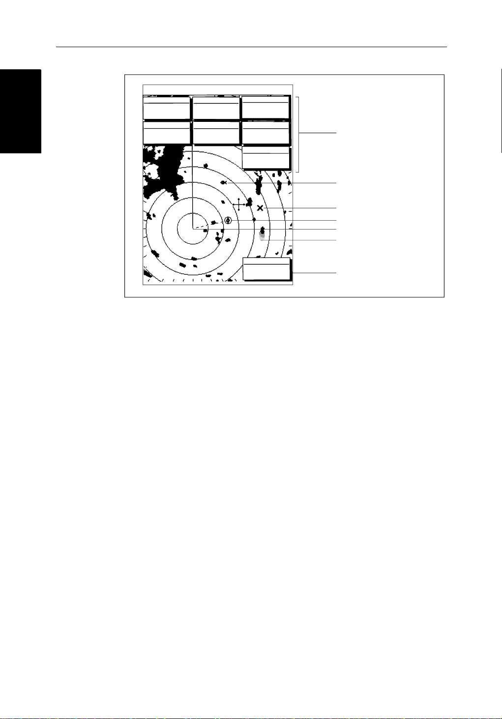
Whenascanner is connected and the radar is in Transmitmode,theradar
pictureprovidesamap-likerepresentationoftheareainwhichthe radar is
operating.Typically,your ship’s position is at the centre of the display,andits
deadaheadbearing isindicatedbyaverticalheadingline,known as theShip’s
Heading Marker (SHM).
Theradarpicturecan be viewed with a variety of fixed orcustomisedrange
scales.Astatus bar at the top of the radarimagedisplaysrange,current
headingandmode indicatorsfor the various options you can set.
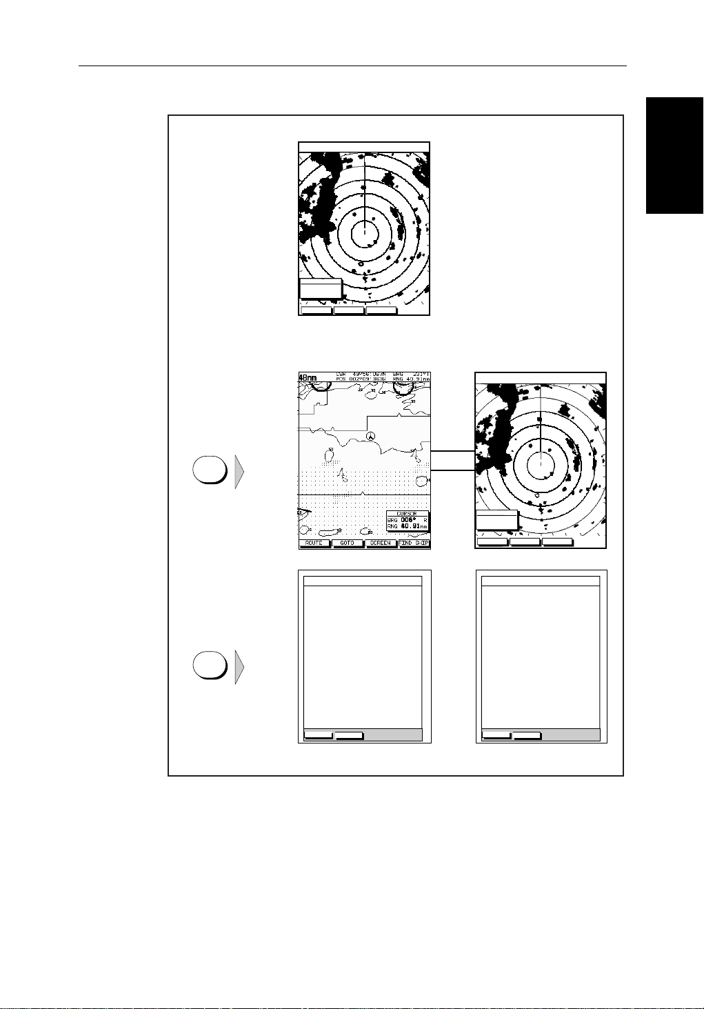
Anexample radar picture is shown on thenextpage,with example radar
returns(echoes)anddefaultPathfinderRadarinformation.TheStatusBaris
alsoillustrated.
Theradardisplaycan show additional information,dependingonyour
currentlyselectedoptions,setupselectionsandthedataavailablefromother
equipment.Theexampledisplaysonthefollowingpagesshowsomeof these
features.
Functionsareavailabletocontrolthedisplayasfollows:
• ZoomtheDisplay
• Offsetyourvesselfromthecentreofthe radar picture
OperationofthesefunctionsisdescribedinChapter 2.
Pathfinder Radar PLUS Display Options
In additionto the display set up options previously described,radarset up
optionsallowyouto customisethe radar image by selecting how radar marks
andElectronicBearingLine(EBL)dataare displayed.You can also specify
timedtransmitmodeand custom range scales.
TheScreenPresentationOptions,describedin Chapter 2allow you to switch
rangeringson/offandwaypointdisplayon/off.
Note:Whenyou turnthedisplayoff andonagain,the ScreenPresentationsettingsareretainedin memory.
Page 23
Chapter 1: 1-11
Default Display
Targets:
Landmass
Channel buoy
Surface
vessel
RM RV3
H-UP
AUTO
T
MARPA
045°
0.28
RINGS
1/2
R
126°T
3nm
CURSOR
BRG
RNG nm
HDG MODE TARGETS SCREEN
Default soft key labels
These can be turned off; press any soft key to re-display them.
Different labels are displayed when you press a key.
IR
Status Bar
Range rings
The number and
spacing depend on
the current range, or
you can turn them off
Ship's Heading
Marker (SHM)
You can hide this
temporarily
Cursor position,
controlled by the
trackpad
Ship's position
You can move this
off-centre if required
Bearing scale,
each tick indicating
o
2
of azimuth
Cursor position box
Shows the current
cursor position as
either Range/Bearing
or Lat/Long. You can
move this box to your
preferred position
on the screen, or
turn it off.
D3600-6
Pathfinder Radar
Pathfinder Radar
PLUS Display Options
PLUS Display Options
Status Bar
Selected range,
in nautical miles
3nm
Range rings
(displayed if
rings are on)
Motion Mode
Relative Motion
True Motion
RINGS
1/2
Range ring interval
Not displayed if
range rings are off
126°T
Current heading
if data available, or
Course Over Ground.
Displayed in degrees
Magnetic or True
Figure 1-3: Radar Display Features
displayed when function on:
Target Vectors
True Vector or
Relative Vector
and vector length
RM RV3
H-UP
Heading mode
Normally Head Up (H-UP);
Course Up (C-UP) or
North Up (N-UP) can be
selected if heading data
available
Auto mode
Gain, Sea,
Tune
AUTO
GST
(Remote rain)
Mode Indicators
Target
Expansion
Rain
Clutter
Guard Zone
Alarms
Interference
Rejection
Wakes
WKS
FTCEXRCGZIR
FTC
D3993-2
Page 24
1-12 hsb
Radar Functions
Radar Functions
3nm
BRG
RNG
CURSOR
063°
1.65
COG
120@T
RR
1/2
R
50°49^13N
001°12^09W
nm
6.3kts
126°T
POSITION
SOG
AUTO
H-UP
GST
TIME
13:48:06
SPEED
5.7kts
DEPTH
FTC
FTC
EX
RC
IR
14.4m
WPT
T 1.20nm
203°
01h:30m
Figure 1-4: Typical Radar Picture
2
PLUS Series CRT Display
Data boxes, showing data
(if available) in the selected
units
Mark, symbol selected using
setup options
Mark, default symbol
Active waypoint - from Chartplotter
Offset centre
Long target wake (short,
medium or long wakes can
be selected)
Waypoint data box, showing
range, bearing and time to go
D3601-2
Radar Functions
Thehsb2(PLUS)seriesPathfinderRadarincludesthe followingfunctions:
• Choiceofrangescalesfrom
• Automaticandmanualcontrolof tuning,gain and sea clutter.
• TwoVariable Range Markers (VRMs) and ElectronicBearingLines
(EBLs),allowingtargetrangeandbearingmeasurements.
VRM/EBLs can be floated.
• Targetwakesandtargetexpansionmode.
• Twoguardzones with alarms.
• Addmarksto record important or dangerous locations.
• ManOverboard(MOB) to navigate back to a person or object.
•10TargetMARPA
OperationoftheseradarfunctionsisdescribedinChapter 3and Chapter 4.
1
/8nm to 72nm (dependent on scanner type).
Page 25

Chapter 1: 1-13
1.4 The Chartplotter Display
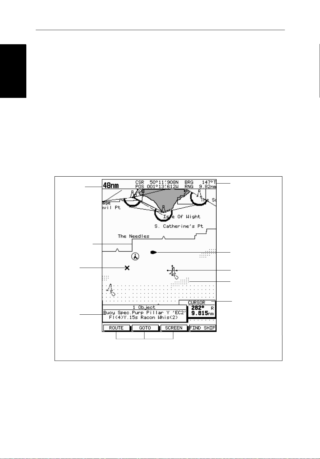
The PLUSseriesdisplaycanincludeaChartplotter.Thechartplotterincludes
asmall-scaleworldmapand detailed navigationinformationisdisplayed
whena cartographicchartcard is installed.The details displayeddepend on
thechartzoom level selected.A plotter mode is provided to enable route
plottingandtrackingatlargescalesevenwhena chart card is not installed, or
whenthe chartis zoomed beyond the available cartographic detail.A typical
chartplotterscreenisshowninFigure 1-5.
ThechartplotterusespositioninformationfromaGPS, DGPS, W AASor
Loran-Cinstrument.Oncethepositionfixhasbeenestablished,yourvessel’ s
position,ifonscreen,isshown as a boat shape pointing inthedirectionofthe
currentheading(orCOG if heading data is not available). If no heading or
COG data is available, the vessel is shown as a circle.
Thechartplotterscreenincludesastatusbarthatdisplayschartscale,with
eithercursorposition,rangeandbearingor,whenthecursorishomedto the
vessel(bypressingFIND SHIP),vesselposition,SpeedOver Ground (SOG),
CourseOver Ground (COG) and fix type (VESPOS, DIF FIX or SDFIX).
The Chartplotter
The Chartplotter
Display
Display
Anywaypointsyou have placed are displayed (unless you turned them off in
ChartSetUp as described in Chapter 7) and thecurrentrouteisshown.
Informationcanbeviewedon-screenby positioningthe cursor over a
waypoint,currentrouteorchartobject.Thechartplotterscreencanalsoshow
additionalinformation,dependingonyourcurrentlyselectedoptions,setup
selectionsanddataavailablefromotherequipment.
Anexample chartdisplay ,in itsdefaultconfiguration,withachartcard
installed,isshowninthefollowingillustration.
Severalfunctionsareavailabletocontrolthedisplayasfollows:
• Zoomin/outand Pan the Display
• OffsettheChartorCenterthe Chart around the V essel
• SynchronizetheChartandRadar(if radar data is available)
OperationofthesefunctionsisdescribedinChapter 2.
Page 26
Chartplotter Display
Chartplotter Display
Options
Options
1-14 hsb
Chartplotter Display Options
Inadditiontothedisplaysetup options previouslydescribed,chartsetup
options,describedinChapter 7,allowyou to customizethechartby selecting:
• Whatcartographicfeaturesandlevelofdetailaredisplayed.
• Chart orientation(northup,headup orcourse up), datums and positionoffset.
• Howwaypointsare displayed(symbolsand numbers) and the availability
ofchartobjectidentificationdata.
• Vectors for heading, COG and tide.
TheScreenPresentationOptions,describedin Chapter 2allow you to switch
theChartGridOn/OffandCustomChartDetails On/Off.
Note:Whenyou turnthedisplayoff andonagain,the ScreenPresentationsettingsareretainedin memory.
2
PLUS Series CRT Display
Chart Range
Chart Boundary
Waypoint
Object data box -
for object selected
by cursor
Figure 1-5: Typical Chartplotter Display
Status Bar
Default soft key labels
These can be turned off: press any soft key to redisplay them.
Different labels are displayed when you press a key.
Vessel Position
Cursor -
selecting chart object
Depth Area
Cursor position box
Shows the current
cursor position as
either Range/Bearing
or Lat/Long. You can
move this box to your
preferred position on
the screen or turn it off.
D4275-2
Custom Chart Details
Thechartplottersetupoptionsincludea sub-menu to customize the
cartographicfeatures.ThismenuallowsyoutoswitchfeaturesOn,Off,or
controlthemusingtheCUSTOM soft key.Thefactorydefaultsettingsforthe
Customchartoptionsareas follows:
Page 27

Chapter 1: 1-15
ON: Charttext,chartboundaries,depthcontours,navigationmarks
andland features.
OFF: Caution and routing data.
CUSTOM: Spot sounding, light sectors, marine features.
Note:The factory default for the CUSTOM settingsisON.
Iconsaredisplayedindetail,depthshadinglimitis10 m and depth contour
displayis0-100 m.
Acompletelistof chart features is given in Appendix C.
Chartplotter Functions
TheChartplotterincludesthefollowingfunctions:
• DisplayC-MAP NT C-Card chart information including Ports and Tides
(ifavailable)
• View chart information (if available) for the Nearest Port
• Place,Move,Eraseand Edit a Waypoint
• GotoWaypoint orCursor
• Create,Save,Name,Editand Follow a Route
Functions
Functions
Chartplotter
Chartplotter
• ReviewRouteandW aypointLists
• Displayvessel’s track;SaveandNamethe Trackforre-calltoscreen
• SmartRoutetomake a track into a route
• MeasureChartDistancesandBearingson-screen
• SetUp Alarms and Timers
• ManOverBoard(MOB) to navigate back to a missingpersonorobject
• DifferentialGPSsetuppage
OperationofthesefunctionsisdescribedinChapter 5and Chapter 6.
Page 28
1-16 hsb
Operating Controls
Operating Controls
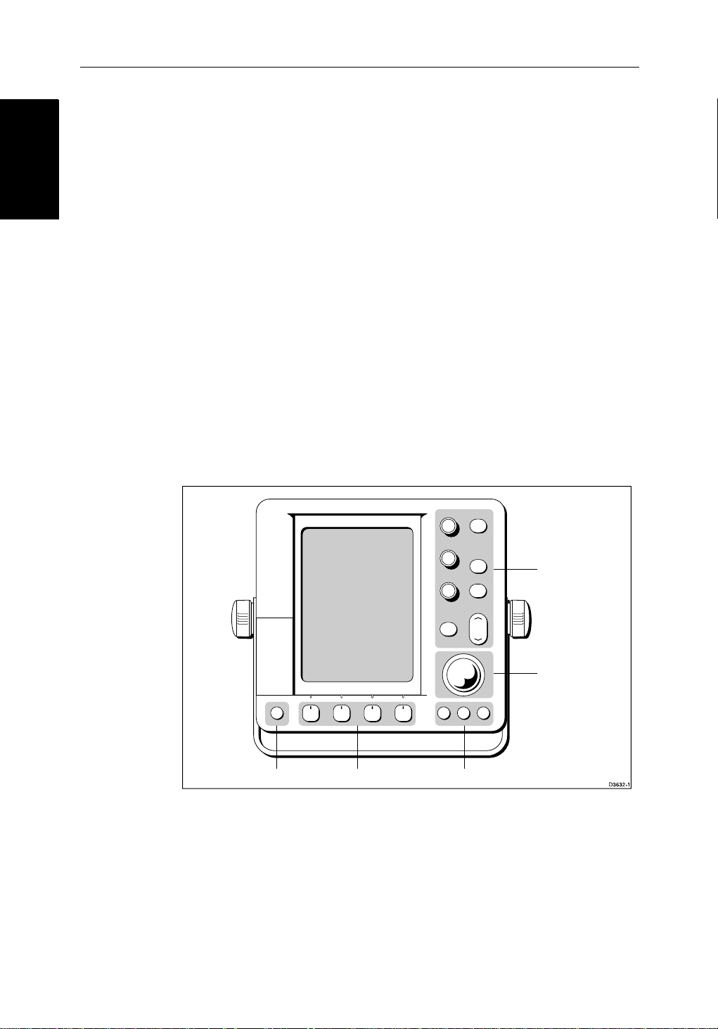
1.5 Operating Controls
You operate the radar and chart using a varietyofcontrols:
• A trackballprovidingup,down,left,right and diagonal controlof an onscreen cursor.
• Ninededicated(labeled)control keys plus threededicatedrotarycontrols.
• Slideradjustments,displayedon-screen,whichyouusewiththerotary
controlstoselectavalue.
• Foursoftkeyswith labels displayedon the screen.
• Pop-upmenus,displayedon-screen,fromwhichyouselectoptions.
• Databaselists,displayedon-screen,whichenableyouto edit items.
Note:The cursor is the cross-hair symbol (+) visibleon the display. You move
thecursorusingthetrackballand useittoselectapositionoritemonthechart.
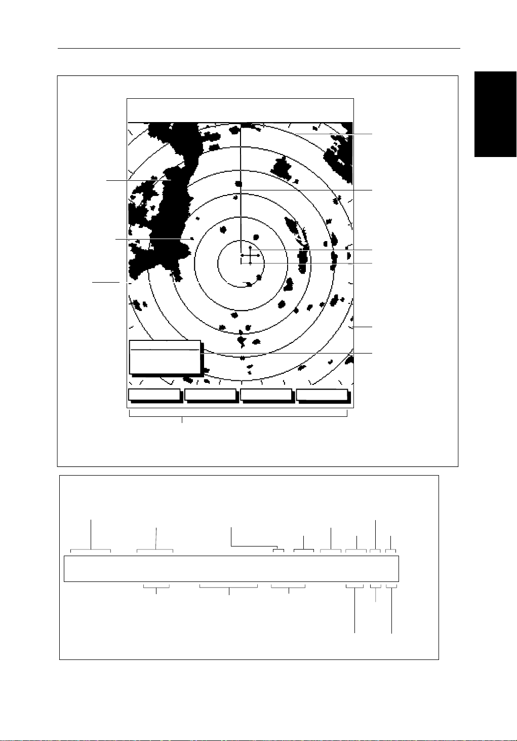
ThecontrolkeysareshowninFigure 1-6.Theyareback-litfornight-timeuse.
Whenyouuse a control, a help message is displayed at the topof the screen
(unlessyouswitchhelpoffas describedin Chapter 7).The following
paragraphsdescribethecontrolsandon-screenfacilitie s.
2
PLUS Series CRT Display
POWER
Figure 1-6: LCD Display Control Keys
Trackball and Cursor
Thetrackballhasseveralfunctions:
• Tomovethe cursor around the screen
GAIN
SEA
MULTI
ALARMS
ENTER CLEAR MENU
Dedicated keysSoft keysDedicated key
DISPLAY
MARKS
VRM/EBL
RANGE
MOB
Dedicated
keys and knobs
Trackball
• Toselectan item from a pop-up menu
• Toadjusta variablesoftkey control
Page 29

Chapter 1: 1-17
Thecursorisused to:
• Selectapositiononthe screen.
• Selectanitem,e.g.guardzoneontheradar,chart object on the chartplotter.
• Selectanareaof the radar image to zoom intoorpan the chart display..
Moving the Cursor
You canpressonanyofthefoursectionsofthe trackball tomovethecursorin
thatdirection(up, down,leftorright),or presstwosectionsat thesametimeto
movediagonally. Thecursormoves fasteras you continue to press the
trackball.Thecurrentcursorpositionisshowninthe cursor data box (if
selected).
Thecursoris normally displayedas a crosshair.However, ifyou have not
movedthecursorformore thanfiveseconds,whenyounextmoveitthe cursor
isoutlinedbya circle so it is easier to locate on the screen.
Note:During many operations you cannot move the cursoraroundthe
screen;if youcannotmovethecursorusingthetrackball,checkthedefaultsoft
keysaredisplayed(unlesstheyhave been switched OFF in system set up). If
not,pressENTER until theyaredisplayed.
Trackball and Cursor
Trackball and Cursor
Context-Sensitive Cursor Control
Thecursoris context-sensitive.Whenthecursorispositionedover special
featuresonthedisplaya text label appearstoidentifythefeatureas detailed in
Table 1-3 .
Moving and deleting items with the context-sensitive cursor
Someitemsontheradar/chartplotterscreen have informationassociatedwith
them.Mostinformationisdisplayedina data box. The context-sensitive
cursorallowsyouto move databoxes. It also allows you to moveordelete
otheritems,suchas radar guard zones. Further details of items that can be
movedor deletedare given in the appropriate sectionsthroughoutthis
handbook.
➤ Tomoveanydatabox or selectable item:
1. Use thetrackballto positionthecursorovertheitemuntiltheitem’slabelis
displayed.
2. Press ENTER totakecontrolof the item, use the trackball to move it to the
requiredposition.
3. Press ENTER againtofix the position,or press CLEAR to abandon the
move.
➤ Todeleteanitem:
1. Use thetrackballto positionthecursorovertheitemuntiltheitem’slabelis
displayedthenpressCLEAR.
Page 30

1-18 hsb
Dedicated Keys
Dedicated Keys
Table 1-3: Context-Sensitive Cursor Text Labels
Text Label Feature Radar/Chart
BOX Data box (any type) Both
MOB Man Over Board marker Both
MRK Radar Mark Both
WPT Chart Waypoint Both
CTR Center of radar Radar
FLT Floating EBL/VRM Radar
GRD Guard zone Radar
MARPA MARPA Target Radar
SHM Ships Heading Marker Radar
VRM/EBL VRM and EBL, 1 or 2 Radar
ZMB Zoom box Radar
2
PLUS Series CRT Display
A
➟B
COG Course Over Ground vector Chart
HDG Heading vector Chart
POS Vessel’s position Chart
RTE Route leg Chart
TIDE Tide vector Chart
Dedicated Keys
The dedicated keys: DISPLAY, MARKS, VRM/EBL, ALARMS, RANGE,
ENTER, CLEAR, MENU and POWER havefixedfunctions;thefunctionsare
similar on allPathfinder displays.For example, ALARMS isused to setup the
systemalarmsonboth a chartplotterand a radar.
Somekeys can be used in twoways:
• Press:Pressthekeymomentarilyandthenreleaseit.Thismethodisused
formostkey operations.
• Pressandhold:Pressthekeyandholdit downforthelengthoftimestated
(forexample,3 seconds),andthenreleaseit.
Whenyou press a dedicated key,oneofthefollowinghappens:
Ruler line Chart
i. The associated operation is actioned, e.g. change chart scale (RANGE).
ii. Apop-upmenu is displayed, providingfurtheroptions.
iii. Asetof soft keys is displayed, providing further functions.
Page 31

Chapter 1: 1-19
Asyou press a key,asingleaudiobeepconfirmsthe key action. If the keypressisnotvalidfor the current screen or mode, three rapid beeps sound to
indicatethatnoresponseisavailable.Ifrequired,youcan turn the key beeps
offaspartof your set up procedure (see Chapter 7).
Rotary Controls and On-Screen Sliders
TheGAIN, SEA andMULTI rotary controls are used to manually adjust
variousparameters.Therotarycontrolscanbeturnedandpressed:
• You can turn the rotarycontroltoadjusttheselectedparameter. Whenthe
controlisuseda slider,displayedalongside,indicates its value.
• You press the MULTIcontrol todisplaya listof options:the adjustment
sliderisdisplayedalongside the control as illustratedbelow. Use the trackballtohighlighttherequiredoption.
Note:Some parameters, such as GAIN, must be settomanual (usingthe soft
keys)beforeyoucan adjustits value using the rotary control.
GAIN
DISPLAY
SEA
MOB
TUNE
CONT
BRILL
LIGHTS
RAIN
FTC
ALARM
TUNE
36%
MULTI
ALARMS
MARKS
VRM/EBL
RANGE
On-Screen Sliders
On-Screen Sliders
Rotary Controls and
Rotary Controls and
Figure 1-7: CRT Display Rotary Controls
Ifyoudo not use the rotarycontrolfor7seconds,theslider and menu are
removed from the display.
Soft Keys
Thefourkeys below the screen are called soft keys because their functions
changeaccordingtotheoperation.Thesoftkeys are grouped into related sets
andsubsetsprovidingaccesstothevariousfunctions.Thesoftkey labels are
displayedonthescreenjustabovethekeys.Thedefaultsoftkeysaredisplayed
untilyoupressa key,orselectanitemonthescreen;thesoftkeys associated
withtheactionarethen displayed.
POWER
GAIN
AUTO MAN
SEA
AUTO MAN
TUNE
AUTO MAN
ENTER CLEAR MENU
D4112-1
Page 32

1-20 hsb
Pop-Up Menus
Pop-Up Menus
TARGETS SCREENHDG MODE
Thecurrentlyselectedsoftkeyoptionis shownbyitsgreenbackground.Ifthe
keytextis displayedin gray rather than in black, it is not currentlyavailable.
Whenyou press a soft key oneofthefollowinghappens:
i. The associated operation is actioned, e.g. NORTH UP.
ii. Asub-setofsoftkeys is displayed, providingfurtherfunctions.
iii. Apop-upmenuis displayed,providingfurtheroptions.
Aswith dedicatedkeys,when you press a soft key a singleaudiobeep
confirmsthekeyaction.Ifthe key-pressis not valid for the current screen or
mode,threerapidbeepssound to indicate that no response is available. If
required,youcanturnthe key beeps off as part of your setupprocedure(see
Chapter 7).
Pop-Up Menus
Pop-upmenususuallyprovide set up options. When a pop-upmenuisonscreen, a set of associated soft keys is also displayed as shown in Figure 1-8.
RDR CHRT
2
PLUS Series CRT Display
D4152-2
You use the trackball to select an option from the menu,thenusethe
appropriatesoftkeytoset the option. For example, you can toggle the OFF
TRACK ALARM on/off.
ALARMS SET UP
ARRIVAL ALARM
OFF TRACK ALARM
ANCHOR ALARM
GROUNDING ALARM
COUNTDOWN TIMER
ALARM CLOCK
SELECT ARRIVAL
ALARM RADIUS
0.01nm
ON
OFF
5M/1.0nm
00:33:00
OFF
D4265-4
Figure 1-8: Typical Pop-up Menu
Page 33

Chapter 1: 1-21
Database Lists
Thewaypoints,routesandtracksthatyoucreateonthechartplotterare stored
indatabaselists.You can view these lists and selectitemsforediting.
WAYPOINT LIST
SYMBOL NAME
WAYPOINT 001
WAYPOINT 002
WAYPOINT 003
WAYPOINT 004
WAYPOINT 005
POSITION
BRG _186°
TEMP
---°
DATE
--/--/--
50°21^966N
001°20^368W
RNG _21.0nm
C
DEPTH
TIME
m
---
--:--:--
Database Lists
Database Lists
GOTO
WAYPOINT
EDIT
WAYPOINT
MAKE NEW
WAYPOINT
WAYPOINT
TRANSFER
D4262-2
Figure 1-9: Typical Database List
Aswith pop-up menus, when a database list is on-screen,asetofassociated
softkeysisalsodisplayed;you use the trackballtoselectanitemfromthelist,
thenusetheappropriatesoft key toedittheitem.Forexample,you can erase a
waypointora route.
Page 34

1-22 hsb
Database Lists
Database Lists
2
PLUS Series CRT Display
Page 35

Chapter 2: Getting Started & Adjusting the Display 2-1
Chapter 2: Getting Started & Adjusting the
Display
2.1 Introduction
Thischapterprovidesinformationandinstructionstogetyoustarted using
yourdisplay. Itwillhelpyouto become familiar with the display and the
functionsofthecontrolsbeforeyoustartusingthe unit. More detailed
informationonoperatingtheradardisplayisprovidedinChapter 3and
Chapter 4.ChartplotteroperatingdetailsaregiveninChapter 5and
Chapter 6.
Conventions Used
Throughoutthishandbook,thededicated(labelled)keysareshownin bold
capitals;forexample,MENU.Thesoftkeyfunctions,menunamesand
optionsareshownin normal capitals; for example, SCREEN.
Operatingprocedures,whichmayconsistofa singlekey-pressor a sequence
ofnumberedsteps,areindicatedby a ➤ symbol inthemargin.
Whentheprocedure requiresyoutopressa softkey, the softkeyiconis shown
in the margin.
Introduction
Simulator
Thedisplayunitincludesa simulatorfunction,thatallowsyou to practice
operatingyourradarorChartplotterwithoutdatafromthescanneror GPS
system.You will need to use thesetupoptionsto switch the display to
simulatormode,asdescribedinSection 2.2. Y oucanuse it in either of two
ways:
• Beforethedisplayunithasbeen installedon your vessel. In this case, you
• Afterthedisplayhasbeeninstall edon your vessel, but while in the marina
Thefollowingsection,Section 2.2, includesinstructionstoviewsimulated
radarandchartimages.
onlyneedto connect the display to a 12V or24V DC power supply,connectingtheredcorefrom the power lead to positive (+) and theblackcore
tonegative(-).SeeChapter 8 forfulldetails.
orat anchor.
Page 36

2-2 hsb
2
PLUS Series CRT Display
2.2 Switching the Display On and Off
Ifyouhave a combined Radar/Chartplotter,thefactorydefaultpower -up
Switching the Display
On and Off
modeisradar.Onceyouhaveusedthedisplayunititpowers-upinthelastused
mode.The followingsectionsdescribethepower-upsequenceinradarand
chartmodes,howto adjust the lighting and how to selectsimulatormode.
Radar Mode
Thissectionexplainshowtoswitchthe radar display and scanner on and off,
andhowto switch the scanner between Transmit,StandbyandScannerOff
mode.
Younormallyoperateyour radarintransmitmode, butyoucanusethe display
unitwithoutthescanneroperatingasfollows:
Standbymode:You should use this mode when youarenot operatingthe
radarforshorttime periods.The scanner does not transmit and the antenna
doesnotrotate,so the radar uses less power.However,thescannerremains
poweredsowhen youreturntotransmitmode,themagnetrondoes notneedto
warmup.
Scanneroffmode: You shouldusethismodewhen you do not requirethe
radar,but youareusingthedisplayunit say,forchart data ortoviewdatafrom
anothersource.Scanneroffmoderemovespowerfrom the scanner.
➤ Toswitchthedisplayon,pressandhold the POWER key untiltheunitbeeps.
Iftheunit waslastusedinRadarmode,thekeyslightup,thedisplayshowsthe
Pathfindergraphic,followedbythestart-upinformationillustratedbelow,and
the radar starts the magnetron warm-up sequence.
GAIN
SEA
MULTI
ALARMS
DISPLAY
MOB
MARKS
VRM/EBL
RANGE
Magnetron warm-up
countdown timer, showing
the number of seconds
remaining before the
radar is ready for use
Software version
numbers
RINGS
WARMING UP
POWER
Until unit beeps
Figure 2-1: Switching on the Radar Display
ENTER CLEAR MENU
D3636-3
Page 37

Chapter 2: Getting Started & Adjusting the Display 2-3
After70seconds,when the magnetron warm-up sequence is complete, the
Standbyscreenisdisplayed,withthetextSTANDBY and a prompt to press the
POWER keytoenterTran smitmode.
➤ ToswitchtheradarscannerfromStand-bymodetoTransmitmode,pressthe
POWER key.
Thescannertransmitspulsedenergywhileitrotates,andtheantennasweep
buildsuptheradarpicture using echoes returnedfrom targets.
GAIN
RINGS
Your vessel's
position
SEA
MULTI
ALARMS
DISPLAY
MOB
MARKS
VRM/EBL
RANGE
On and Off
Switching the Display
POWER
ENTER CLEAR MENU
Figure 2-2: Radar Transmit Mode
➤ Youcan switchonand adjust the display backlighting and contrast as
describedlaterinthischapter.
➤ ToswitchtoStand-bymode,press the POWER key.
Thedisplayreturnstothe Stand-byscreen,andthe scannertransmissionand
rotationstops.
➤ TouseScanneroffmode:
1. Ensure that the radar isinStandbymode,warmingup,or (if the unit is a
Repeater)displayingamessagethatradardataisnot available.
2. Press theCLEAR key.The messageSTANDBY. RADAR DATA NOT AVAILABLE
appearsintheradarpicture.The scanner is powered down and thetimer,if
running,iscleared.
T oreturn to radar operation, press the POWER key.The warm-up countdown
isdisplayedandtheradargoesintoStandbymode.YoupressPOWER againto
switch to Transmit mode when required.
D3637-3
Page 38

2-4 hsb
2
PLUS Series CRT Display
Chart Mode
➤ Toswitchthedisplayon,pressandhold the POWER keyuntiltheunitbeeps.
Switching the Display
On and Off
Ifthedisplaywas last used in chartplotter mode, the keys light up andthe
Raychartgraphicisdisplayed,followedbythecaution:
CAUTION:
Raychartchartdisplaysarebasedoncartographicdatathat
C-MAPbelievestobeaccurate.However, you shouldnotrelyonthese
displaysasyourprimarysourceofnavigation.Rather, your Raychart
shouldbeusedonly as a backuptoofficialgovernmentchartsand
traditionalmethodsofnavigation.
Whenyouhaveread andunderstoodthecaution, pressthe CONTINUE softkey.
The chart is displayed.
Ifthisisthe first time the chartplotterhas been turned on, and no chart card is
installed,thedisplayshowsthesmall-scaleworldmapand the default soft
keys.Otherwise,thedisplayshowstheselectedchartareaand any data that
weredisplayedwhenthedisplaywas last used.
Switch Off
➤ Toswitchthescanneranddisplayunitoff,pressandholdthePOWER key for
threeseconds.Acountdowntimer is displayedas shown below:
GAIN
DISPLAY
SEA
MOB
MARKS
Countdown timer:
number of seconds
to power off
POWER
MULTI
VRM/EBL
RANGE
ALARMS
ENTER CLEAR MENU
3
SECONDS
D3638-2
Figure 2-3: Switch Off
Whenthe counterreacheszeroa beep sounds, and the display unit switches
off.ReleasethePOWER key.
Note:Switchthe display unit off before you remove the powercord.
Page 39

Chapter 2: Getting Started & Adjusting the Display 2-5
Note:You do not need to changetoStandbymodebeforeturningoff the display:ifyouturnthe radar displayoffwhileitisinTransmitmode, the scanner
isalsode-activated.
Simulator Mode
Whensimulatormode is on a simulator data box isdisplayed.
Whenthedisplay isswitchedoffthenonagain,simulatormodeismaintained.
Itisrecommendedthatyou select the System Set Up Menuandswitchoff
simulatormodewhenyou have finished.
Simulator Mode
MENU
SYSTEM
SET UP¬
➤ Toviewasimulatedimage:
1. Press MENU followedbytheSYSTEM SET UP soft key.
Thesetup menu pop-up is displayed.
2. Usethetrackballtomovetheselectionbarover theoptionSIMULATOR.The
simulatorsoftkeysaredisplayed.
3. In the system setupmenu, press RADAR toviewa simulatedradarimage,
DATA toviewthechartdisplaywithsimulatedposition,orBOTH toview
simulatedradarandchartdata.
4. Press ENTER twicetoreturnto the default display.
Note:Any waypoints placed on the chartplotter in simulator mode are retainedinthedatabase list and are available for use in routes.
Lighting, Brilliance and Contrast
You can change the levels of brilliance and contrast for the screen and the key
lighting.Thefactorydefaultforcontrastandbrillianceis40%;undernormal
daylightconditionsvaluesintherange40-50%are adequate.If you need to
changethecontrastandbrilliancebeawareof the following:
• ExcessivesettingsforprolongedperiodswilldamagetheCRT. The
newcontrastandbrilliancelevelsareretaineduntilyouresetthem,unless
yousetthe controlverylow(30%) orveryhigh(70%); inthiscase,the contrast/brillianc ewillberestoredto40%whenyouturnthedisplayoffandon
again.
• Excessivecontrastusedtocompensateforlowbrilliancedamagesthe
CRT, also excessive brillianceused to compensate for low contrast
reducesthesharpnessofthe image.
Brillianceandcontrastshouldthereforebesettowithin10% of each
other.
Page 40

and Contrast
2-6 hsb
➤ Tochangethelighting,brightnessandcontrast:
1. PresstheMULTI rotary control todisplaytheMultimenu.Usethetrackball
tohighlighttherequiredoption.
Lighting, Brilliance
GAIN
SEA
GAIN
AUTO MAN
SEA
AUTO MAN
TUNE
AUTO MAN
TUNE
CONT
BRILL
LIGHTS
RAIN
FTC
ALARM
TUNE
36%
MULTI
ALARMS
DISPLAY
MOB
MARKS
VRM/EBL
RANGE
2
PLUS Series CRT Display
POWER
ENTER CLEAR MENU
D4112-1
Figure 2-4: CRT Display - MULTI Rotary Control Operation
2. Turnthe MULTI key to movethe sliderup or down. The lighting,contrast
orbrilliancechangesasyou turn the knob, so that you canseetheeffectof
youradjustment.
3. When you have set the control to the level you require,eitherusethetrackballtomove to the next option you wish tochange,orpressENTER or
CLEAR to clear the control display.
Thedisplayreturnstothe previous display,withthe new setting.
Thenew lightinglevelis retaineduntilyou reset it and is remembered when
youturnoffthedisplay.
CAUTION:
Anexcessivecontrastorbrightnesssettingforprolongedperiodswill
reducethelifeofthe CRTdisplayand will unnecessarily increasepower
consumption.
Screen Saver
Whena bright image is left in oneplaceon the phosphor for some time, the
lightoutputof that portionof the phosphor is marginally reduced. Phosphor
damageisnoticeableasa slight trace of a previous image when anewpicture
isdisplayed.Theunitis equipped with a screen saving facility to assist with
protectingthe CRTtubefromthisdamage.Thescreensaver movesthepicture
slightlywithinthesurround,whichmaybe noticeable as an occasional small
horizontalorverticaldisplacementofthepicture.Theeffectisintentional.
Page 41

Chapter 2: Getting Started & Adjusting the Display 2-7
2.3 Controlling the Display
You control the display using the cursor and control keys. Youstartall
operationsfromthedefaultscreen,thatisthe defaultsoftkeys are displayed:
Chart
GOTO SCREENROUTE FIND SHIP
D4160-1
Radar
Display
Controlling the
TARGETS SCREENHDG MODE
Whenyouhave completed an action using the soft keys, press ENTER or
CLEAR to returntothe default screen;you may need to press ENTER or
CLEAR several times to back-trackthroughthesoftkey hierarchy .
Note:If you have set up your systemsothatthe defaultsoftkeys are not displayedallthe time, press any soft key to display the labels.
Theremainderofthis section describeshow to select the mode of operation
andswitchhalf-screenwindowson/off.Thefollowingsectionsdescribehow
tosetup the display for the Radar and fortheChart.
Thecontrolsaresummarizedinthefold-outillustrationonpages 2-11
and2-12.
Selecting the Mode of Operation
You use the DISPLAY keyto selectthe full-screenmode.
Ifthe data is available on your system, the following modes (described on
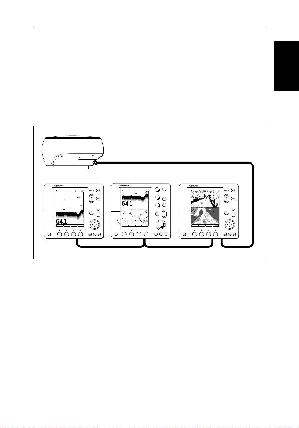
OperatingModeson page 1-6) can be selected:
•Radar
•Chart
MARPA
D4152-3
•Datalog
TheDISPLAY keyalso accessesthe soft keys for the half-screen window
options.
2
hsb
Note:If your
displaysystemincludesaFishfinderdisplay,refertothe
Owner’sHandbooksuppliedwithyourFishfinderfor operatingdetails.
Page 42

Selecting the Mode of
Operation
2-8 hsb
➤ Tochange themode,pressthe DISPLAY keytoshowtheDISPLAY pop-up,then
DISPLAY
pressagaintocyclethroughthe modes available,shown in the Figure 2-5.
2
PLUS Series CRT Display
Figure 2-5: Using the DISPLAY Key
Theselectedmodeis shown by an icon witharedborderand the mode is
displayedonthescreen.The associated half-screenwindowsoftkeysarealso
displayed.
Whenthe requiredmode is shown, press ENTER orCLEAR. The default soft
keysaredisplayed.Theselectedmodeis shown full-screen; in Radar and
Chartmodeyou can switch on half-screen windows for additional display,as
describedinthefollowingsection.
IfyoupressDISPLAY again,thepop-upand soft keysforthecurrentmode are
shown.
Selecting a Half-Screen Window for Display
Note:Windows can only be used with Radaror Chart screens, they are not
availableonthedatalog screen.
➤ Toselectawindowfordisplay:
1. From the full-screenRadarorChartmode,presstheDISPLAY key.The
followingsoftaredisplayedwithan image of each available window:
Page 43

Chapter 2: Getting Started & Adjusting the Display 2-9
Radar:
DISPLAY
WINDOWS
OFF ON
SELECT
WINDOWS
ZOOM...
D4208-2
Chart
DISPLAY
WINDOWS
OFF ON
SELECT
WINDOWS
D4156-2
2. Toselectadifferentwindow, presseither SELECT WINDOWS softkeyuntil
therequiredwindowishighlighted.Ifnecessary, this will toggle windows
on.PressENTER.
3. Totogglewindowsoff,presstheWINDOWS OFF ON soft key.
Figure 2-6 shows the half-screen horizontal windows (in radar mode).
Switching Control Between Radar & Chart Screens
Ina combined or an integrated system, to switchcontrolbetweenradarand
chart,youcanchangethe full-screenmodeusingthe DISPLAY key .
Alternatively, when you havebothradarandchart displayedin half-screen
windowsthesoftkeyRDR CHRT letsyou toggle operatingcontrolbetweenthe
radarandthe chart window.
Operation
Selecting the Mode of
DISPLAY
Ifa window is active, i.e. control of the cursor via the trackballisavailablein
thatwindow, andyouswitchwindows off,controlautomatically returnstothe
full-screen(upperwindow)mode.
Radar:
TARGETS MORE¬HDG MODE
RDR CHRT
D5668_1
Chart:
GOTO MORE¬ROUTE
RDR CHRT
D4168-1
➤ Tochangetheactivewindow, press the RDR CHRT softkeytotogglecontrol
betweentheradarandchart display.The current active display is highlighted
in red on the RDR CHRT labelandthecursorappearsinthatwindow.
Returning to the Full-Screen Display
To returntothefull-screendisplayyoucanturn windows off,as previously
described.Alternatively, to return to full-screen display:
➤ Press and hold theDISPLAY keyfor2 seconds to return to the currently
selectedfull-screen(upperwindow)display
Page 44

2-10 hsb
2
PLUS Series CRT Display
Selecting the Mode of
Operation
CDI Window
WINDOWS
OFF ON
SELECT
WINDOW
ZOOM
OFF ON
BDI Window
WINDOWS
OFF ON
SELECT
WINDOW
ZOOM
OFF ON
Navdata Window Chart Window
WINDOWS
OFF ON
SELECT
WINDOW
ZOOM
OFF ON
WINDOWS
OFF ON
Figure 2-6: Radar Half-Screen Window Options
SELECT
WINDOW
RDR CHRT
ZOOM
OFF ON
D4150-1
Page 45

Chapter 2: Getting Started & Adjusting the Display 2-11
FOLD OUT SHEET RADAR
Operation
Selecting the Mode of
Page 46

Selecting the Mode of
Operation
2-12 hsb
FOLD OUT SHEET CHAR T
2
PLUS Series CRT Display
Page 47

Chapter 2: Getting Started & Adjusting the Display 2-13
Customizing the Screen Presentation Options
TheSCREEN softkeyletsyouswitchthefollowingscreenpresentationoptions
onor off:
Radar:
SCREEN
SCREEN
CRSR BOX
OFF ON
BOX
CRSR BOX
OFF ON
RNGE RNGS
OFF ON
DATABOXES
OFF ON
WAYPOINT
OFF ON
D3643-2
Chart:
CRSR BOX
OFF ON
CHRT GRID
OFF ON
DATABOXES
OFF ON
CUSTOM
OFF ON
D4177-1
Switching the Cursor Data Box On and Off
Thecursordata boxprovidesthecursor’s positioninlatitude/longitudeand/or
bearing/range.Ifyouwishtoseea full image, you can switch the data box off.
➤ Tocontrolthecursordatabox:
1. Press the SCREEN softkey.
2. PresstheCRSR BOX softkeytotogglethesettingfromOFF to ON orfromON
to OFF.
3. Toreturntothedefaultsoftkeydisplay, pressENTER.
➤ Youcanusethecontext sensitivecursorto selectandmovethecursor databox
(thelabelBOX is displayed).SeeMovinganddeletingitemswiththe context-
sensitive cursor onpage 1- 17
Options
Customizing the
Screen Presentation
SCREEN
RNGE RNGS
OFF ON
Switching Radar Range Rings or Chart Grid On and Off
Theradarrange rings can be turned on or off.Theyarenormallylefton, but
youmaywish toturnthemoffifyouare usingVRM/EBLsorguard zones(see
Section 3.4 andSection 3.5) to make the display clearer.
TheChartplotterdisplayincludesgridlinesoflatitudeandlongitudewhich
youcan use to help determine position on the chart. The grid linescanbe
switched on if required.
IfyouareinChartmodetheRNGE RNGS softkeyisreplacedby the CHRT GRID
soft key .
➤ Toturntherangeringsor chart grid on or off:
1. Press the SCREEN defaultsoftkey.
2. Press theRANGE RINGS or the CHRT GRID softkey totogglethesettingfrom
OFF toON orfrom ON toOFF.
To returntothedefaultsoftkeydisplay, pressENTER.
Page 48

Options
Screen Presentation
2-14 hsb
Data Boxes
Agroupofuptosix databoxescanbedisplayed,if theinformationisavailable
onyour system. You select which dataisdisplayedinthe boxes during
Customizing the
systemsetupas described in Chapter 7:Setting Up the SystemDefaults.
Thedefaultdata box positions are along the bottom of the display. Each box
canbemovedtotherequiredpositiononthescreenusingthecontext-s ensi tive
cursor.
Note:Ifyouselect BDI,CDIorNavDatafor displayinahalf-screenwindow,
thedataboxesare temporarilyhidden.
2
PLUS Series CRT Display
SCREEN
SCREEN
DATABOXES
OFF ON
BOX
Atanytime, you can switchthe groupof databoxesonoroffusingtheSCREEN
softkey. Whenfirstinstalled,theboxesare allOFF.Whenthedisplayunitis
switchedoffand on again,thedataboxesreturn to theirlast-usedstates(ON or
OFF)and positions.
Note:The SCREEN softkeydoes not control the sixteen data boxes that can be
displayedinthehalf-screenwindow.
➤ Toswitchthegroupofdata boxes on or off:
1. Press the SCREEN defaultsoftkey.
2. Press the DATABOXES softkeytotogglethesettingfromON toOFF or from
OFF toON.
To returntothedefaultsoftkeydisplay, pressENTER.
Ifyouturn the data boxes on and none aredisplayed,youneed to select the
onesyourequireusingthe system set up menu, as describedinSection 7.3,
SystemSetUp Parameters.
➤ Youcan usethecontextsensitivecursortoselectand move any data box (the
label BOX isdisplayed).See Movingand deleting items with the context-
sensitive cursor onpage 1- 17
Waypoint Display - Radar mode
SCREEN
WAYPOINT
OFF ON
Ifyouare currently going to a waypoint, you can displaytheactivewaypoint
onthe radar picture.The waypoint may have been generated locally on the
chartplotter, orreceivedviatheSeaTalk orNMEAinterface.
Note:Ifyou usetheGOTO CURSOR function,theactivecursorisdisplayedas a
lollipopsymbolontheradar.
➤ Todisplaytheactivewaypoint:
1. Press the SCREEN softkey.
2. Press the WAYPOINT soft key totogglethesettingON.
To returntothedefaultsoftkeydisplay, pressENTER.
Page 49

Chapter 2: Getting Started & Adjusting the Display 2-15
Thestandardradarpictureisdisplayedagain, with the activewaypointjoined
toyourvessel’ sposition by adottedline.If the waypoint is off-screen,the
dottedlineisextendedto the edge of the radar picture.
Active waypoint
D3989-2
Figure 2-7: Active Waypoint on a Radar Display
Custom Options - Chart mode
Whenchartdetailshavebeen customizedinthe Chart Set Up menu (as
describedin Section 7.7)theSCREEN softkeycanbeusedto switchthecustom
chartoptionsofforon:
Whenset to ON, all chart options set to CUSTOM inthe CustomizeChartmenu
aredisplayed;whensetto OFF, options settoCUSTOM are not shown.
Options
Customizing the
Screen Presentation
SCREEN
CUSTOM
OFF ON
Thefactorydefaultforcustomchartoptionsis ON.
➤ Toswitchthecustomizedoptionsonoroff:
1. Press the SCREEN defaultsoftkey.
2. Press the CUSTOM softkey to toggle the setting from OFF toON orfromON
to OFF.
To returntothedefaultsoftkeydisplay, pressENTER.
Page 50

2-16 hsb
2.4 Radar Display Control Functions
Thissectiondescribeshowtouse the radar controls to:
Radar Disp lay Control
Functions
Using the Zoom Function
• Usethe zoom functionto enlargeaselectedarea.
• Offsetthecenteroftheradardisplay.
• Momentarilyhidetheship’sheadingmarker(SHM).
Ifyou wish to see a section of the radarpictureinmoredetail,youcanuse the
Zoomfunctiontomagnifytheselectedareato twice its size. There are two
zoomoptions:
• ZoomInto-Theenlargedareaisdisplayedinaquarter -screen ZoomWin-
dowin the lower right corner of the screen. A boxin the originalradarpictureindicatestheenlargedarea;youcanmovethisusing the contextsensitivecursor, therebychangingtheimageinthe Zoom Window.
Note: If the areayouwishtoenlarge is inthequarterofthe screenthatwillbe
coveredbytheZoom Window, you should offset the center (see the nextsection)tomove the area to another part of thescreenbeforeselectingZoom
mode.
• ZoomFrom- The enlargedareaisdisplayedin themainwindow, with the
originalradarpictureinaquarter-screenwindowinthelowerrightcorner
ofthescreen.Aboxintheoriginalradarpictureindicatestheenlargedarea;
youcanmovethis usingthecontext-sensitivecursor,therebychanging the
zoomedimage.
2
PLUS Series CRT Display
Note: YoucannotuseZoom andWindowsatthe sametime:if youturnoneon,
theotheristurned off automatically,andrestoredwhenthelatter isturnedoff
again.
➤ Toenlargeanarea:
1. Press the DISPLAY key.Thesoftkeysare updated.
DISPLAY
WINDOWS
OFF ON
SELECT
WINDOWS
ZOOM...
D4208-2
2. Press the ZOOM sof tkey todisplaythefollowingsoftkeys
x4
x2
ZOOM OFFINTO WIN FROM WIN
D4188-2
Page 51

Chapter 2: Getting Started & Adjusting the Display 2-17
3. Press the required zoom option soft key, INTO WIN orFROM WIN.
Thesoftkeys are cleared, and the cursor has control of thezoombox that
indicatestheareatobeenlarged.ThisisindicatedbythelettersZMB in
inversevideo,andthefour-headedcursorsymbol.Thezoom box defaults
toitslast-usedpositionsincepower-on.
4. Use the trackballtomovethezoom box to the required area, then press
ENTER. The selected area is shown in enlarged format, either in the quarter-screenZoomwindow(INTO WIN)orinthemain window (FROM WIN).
PressDISPLAY thenENTER toexittheZoom mode.
Alternatively, you can press and holdDISPLAY for2seconds.
➤ Youcan usethecontextsensitivecursortoselectand move the enlargedarea
ZMB
inviewin the window (the label ZMB isdisplayed).SeeMovingand deleting
itemswiththecontext-sensitivecursoronpage 1-17
Offsetting the Center
RINGS
3nm
BRG
RNG
CURSOR
033° R
1.78nm
1/2
126°T
Figure 2-8: Radar Display Zoom Window
Offsetting the Center
Theradarpictureis normally shown with your vessel at the centerofthe
display. However,you canmovethe center,sothatyourvesselisoffsetbyup
to66% of the radius, anywhere on thescreen.
RM RV3
AUTO
H-UP
T
ZMB
RADAR ZOOM ( x2 )
IR
Zoom Box, indicating the
enlarged area. You can move this
using the context-sensitive cursor,
to change the image in the Zoom
Window
Zoom Box cursor text
Zoom Window, providing a
times 2 enlargement of the area
shown in the Zoom Box
D3972-2
Note:You cannot offsetthecenter when the radar display is set to the longest
rangescale.
Page 52

2-18 hsb
2
PLUS Series CRT Display
➤ Youuse thecontextsensitivecursortoselectandmovethe centerof the radar
CTR
Hiding the Ship’s
Heading Marker
(SHM)
picture(thelabelCTR isdisplayed). See Moving anddeletingitemswiththe
context-sensitivecursoronpage 1-17
DEPTH
14.4m
Bearing scale markers
adjusted to point
towards the offset
centre position
203°
01h:30m
WPT
T 1.20nm
Offset centre
D3973-1
Figure 2-9: Radar Display with an Offset Center
➤ Toreturnthecenteroftheradarpicturetothecenterofthe screen,selectthe
CTR
centerpoint(CTR ) then press theCLEAR key. The center is always reset to the
centerofthedisplay when you turn on the Radardisplay.
Note:Whenthe center is offset, additional range rings are displayed to the
edgeofthe radarpicture,atthe standardringintervalfor thecurrentrange.If
youhaveselectedthelongestrangescale,you cannot offset the center.
Hiding the Ship’s Heading Marker (SHM)
Theradarpictureincludestheship’sheading marker,whichisalinefromyour
vessel’s positiontotheedgeof the picture at the vessel’scurrentheading.In
thestandardHeadUp mode, the heading marker is always a verticalline.
Ifyouwish to check for small targets that may be hidden undertheheading
marker,you canhide it momentarilyusingthe context-sensitivecursor.
➤ Tohidetheheadingmarker:
1. Position the cursor over the headingmarker,sothat the text SHM isdisplayed.
2. Press and hold CLEAR. The headingmarkerishiddenuntilyou release the
CLEAR key.
Page 53

Chapter 2: Getting Started & Adjusting the Display 2-19
2.5 Chart Display Control Functions
Moving Around the Chart
You will normally operate the chartplotter with the chart showingyour
vessel’s currentlocation.ThedefaultorientationisNorth-Up,andthevessel
movesacrossthescreen. You will needtomovethechartifyour vesselmoves
outofthe area currently displayed,or if you wish to examine orplace
waypointsinanotherarea.Alternatively, you canhome the cursor onto the
vesselusingFIND SHIP.
Thereare four ways in which you canmove the chart:
• Usethetrackballtomovethecursortotheedge of the chart. The chart will
panacross.Thismethodisusefuliftheareayouwishtoseeisonlyjustoff
the screen.
• Usethe context-sensitivecursortochangethechartcenter .
• Automaticallyre-centerthevesselusingtheFIND SHIP softkey.
• Changethechart scaletozoomoutand in toanewareacentered onthecursorposition.Thismethodisusefulif the area you wish to seeisalong distance away.
Functions
Chart Display Control
Changing the Chart Center
You can move theareaofthechart displayedon the screen using the contextsensitivecursor. This allowsyouto centeryour vessel in the middle of the
screen,ortomove the chart so that your vessel isdisplayedoff-cent er
anywhereonthe screen.
➤ Tocenter the chart:
1. Usethetrackballtomovethe cursortothevessel’s position.Thecursortext
POS
POS
POS isdisplayed.
2. Press CLEAR. The chart is moved so thatyourvessel’ sposition is in the
centerofthescreen.
➤ Youuse thecontextsensitivecursortoselectandmoveyourvessel’ sposition
off-center(the labelPOS is displayed).SeeMovinganddeletingitemswiththe
context-sensitivecursoronpage 1-17.
Page 54

Chart
2-20 hsb
Moving Around the
D4278-1
Figure 2-10: Changing the Chart Center
Using FIND SHIP
2
PLUS Series CRT Display
FIND SHIP isusedin chartmodetore-drawthechartwiththevesselatthecenter
andthecursorhomed onto the vessel.
GOTO SCREENROUTE FIND SHIP
D4160-1
Whenyou press FIND SHIP the following occur:
• Thechartis re-drawnwith the vessel’spositioninthecenter.
• Thecursorishomed onto the vessel position and moves with it.
• Whenthe vessel moves near the edge of thechartwindow,the chart is
redrawntoplacethevesseland cursor at the center again.
• Thestatusbarindicatesvesselposition,speedandcourseover ground.
➤ Toreleasethecursorfromhomedmodepressthetrackpadtrackballtomove
thecursorawayfrom the vessel’scurrentposition.The statusbarshowsthe
cursorposition,rangeandbearing.
Synchronize the Radar and Chart
Ifyouhave a combined radar/chartplotterdisplay, withchartandradar
windowson and you have selected Radar/Chart Synch in Chart Set Up
(Section 7.7, Chart Set Up Parameters),FIND SHIP can beusedtosynchronize
theradarand chart images. When you press FIND SHIP thefollowingoccur:
• Thechartis redrawn sothatitscenter positionmatchesthatof theradardisplay.
Page 55

Chapter 2: Getting Started & Adjusting the Display 2-21
• Theradaris redrawn to the scale and heading mode ofthe chart.
• Theradaris set to Truemotionso that the radar and chart images remain
synchronisedasthevesselmoves.
Note:Dependingon the topology of the coastline, the radar returns may not
relatetothechartedshoreline,theradarimagewillthereforebedifferentto
thechartdisplay.For example,agentlysloping beachwithacliffseveral hundredmetresbeyondthe chartedcoastline,thecliffis not shown on the chart
butwill be displayed on the radar image.
Changing the Chart Scale
TheRANGE keyallows you tochangethechart scale so that you can see a
smallerorlargerareaonthescreen.
Plottermodeisavailabletoallowyou to zoom into a smallerarea,evenwhen
nochartdata is availableforthatscale.Section 7.7describeshow tosetplotter
modeon/off.
You can change the chartscalefortwopurposes:
• Tosee eithermoredetail(of a smaller area)or a larger area (in less detail)
onthe screen.
Chart
Moving Around the
• Tomovethedisplaytoanotherarea of the chart, by zooming out to a small
scalechart,thenzoomingin on another position centeredon the cursor.
Thecartographicdetailavailableonchartsvariesaccordingtothechartscale
andsomeareas includedetailat smallerscalesthanothers.This can cause
blankareasonthe displaywhen adjacent areas with differentlevelsofdetail
aredisplayed.To reducethisaffectyoucanusetheChart Set Up options (see
Section 7.7)toset chartdisplaydetailtosimple.Then, asyouzoomin, charted
areasaredisplayedbutwith less detailshown.
Eachtime you press the RANGE key, the chart scale changes to thenext
availablesetting.Thestatusbarindicatesthedistancefromtoptobottomof
thescreen,innauticalmiles.
Vertical distance
displayed on chart
6nm
Status Bar
CSR 50 45'980N
POS 001 01'490W
D4175_1
RANGE
Increases the
chart distance
Decreases the
chart distance
Figure 2-11: Changing the Chart Scale
Page 56

2-22 hsb
➤ Tochangethescalequickly, pressand hold the required arrowonthe RANGE
key.
RANGE
Moving Around the
Thedistanceindicatorattheleft-handendof the status bar is updated
wheneveryouchangethe chart scale.
2
PLUS Series CRT Display
Chart
RANGE
➤ Tozoomintoa larger-scale(moredetailed)chart:
1. Use the trackball to position the cursor in the area you wish to see in more
detail.
2. Press the lower partoftheRANGE key to zoom into the area.
Thesectionofthechartaroun dthe cursor is enlargedtofillthe screenwith
alarger-scalechart showing moredetail.Thecursorisnow positioned in
the center of the screen.
Thedistanceindicatedatthetop left of the screen is updated.
3. If further chart enlargement is availableusing the current chart card you
canpressthebottom of the RANGE keytozoom in again, re-positioning
the cursor first if required.
Anarea of further chart detail is indicated by a box around the areaas
shownin Figure 2-12.
Chart Boundary indicates further
detail is available inside
Figure 2-12: Chart Boundaries
4. When no furtherchartdetailisavailable,asyoupress the bottom of the
RANGE key,theeffectdependsonwhetherPlotterModeis on or off as
follows:
D4279-1
Page 57

Chapter 2: Getting Started & Adjusting the Display 2-23
• IfPlotterModeis Off,the chart scale remains unchanged,indicating
thesmallestchartscaleisdisplayed.
Note:If PlotterMode is Off and the cursorishomedtothe vessel (see
Using FIND SHIP onpage 2-20),ifthevessel movesoutsideanar ea of
availablecartography, thechartwillautomaticallyre-scaletothenext
rangewithcartography.
• IfPlotterMode isOn,thescaleis decreasedandthemessageNO CHART
DATA isdisplayed.Thevessel,waypoints,routesandtracklinesaredis-
playedwithoutcartography.
Thechartinformationisrestoredwhenyou returntoachartscaleforwhichthe
information is available.
RANGE
➤ Tozoomouttoasmaller-scale(lessdetailed)chart,simplypresstheupperpart
oftheRANGE keyasmanytimesasrequired.
2.6 Typical Chart Scenarios
Thefollowingillustrationsprovideoperatingguidelinesfortypicalnavigation
scenarios.These scenarioscanbeusedas atrainingguide;they showyouhow
toperforma particularoperationandtheyintroducemanyof the chartplotter
functions.
Eachscenarioindicatesthekey pressesrequiredtoperformparticulartasks.A
typicalchartplotterscreenimageisshownforeachtask.
Thescenariosassumeyou have read the previous sections of this chapter and
thatyouare familiar with the Operating Controls. Full operatingdetailsfor
eachfunctionareprovidedinChapter 5and Chapter 6.
Typical Chart
Scenarios
Operatingguidelinesareprovidedforthefollowingscenarios:
• WorkingwithWaypoints
PlaceaWa ypoint
Gotoa Waypoi nt
• Makeand Follow a Route
CreateaRoute
Followa Route
• ReviewthePassagePlan
Vi ewRouteInformation
Changethe SOG, Hours and ETA.
• DisplayingtheRadarImageand SynchronizingRadar & Chart
ChangingtheFull-ScreenMode& Selecting Half-ScreenWindows
RadarandChart Synchronization(FindShip)
CursorEcho
Page 58

2-24 hsb
Place and Goto a Waypoint
GAIN
DISPLAY
2
PLUS Series CRT Display
1
Place and Goto a
Waypoint
SEA
MULTI
ALARMS
MOB
MARKS
VRM/EBL
RANGE
1. Press MARKS
2. Position Cursor as required
GAIN
SEA
MULTI
ALARMS
DISPLAY
MOB
MARKS
VRM/EBL
RANGE
2
GAIN
SEA
MULTI
ALARMS
DISPLAY
MOB
MARKS
VRM/EBL
RANGE
Press the soft key
3
Press the soft key to go to the
waypoint selected by the cursor.
D4204-1
Page 59

Chapter 2: Getting Started & Adjusting the Display 2-25
GAIN
SEA
MULTI
ALARMS
DISPLAY
MOB
MARKS
VRM/EBL
RANGE
4
The vessel navigates towards the
target waypoint
Waypoint
Place and Goto a
See:
5.3 Working wth Waypoints and
Go to an Individual Target Point
D4204-2a
Page 60

2-26 hsb
Make and Follow a Route
Make and Follow a
2
PLUS Series CRT Display
1
Route
GOTO SCREENROUTE FIND SHIP
Press the soft key
2
EDIT
ROUTE
CLEAR
ROUTE
MORE¬
GAIN
SEA
MULTI
ALARMS
DISPLAY
MOB
MARKS
VRM/EBL
RANGE
Press the soft key
3
1. Position Cursor - in this
example over an existing
waypoint
MAKE
ROUTE
GAIN
SEA
MULTI
ALARMS
DISPLAY
MOB
MARKS
VRM/EBL
RANGE
2. Press the soft key
4
Position Cursor for next
waypoint, then press soft key.
Repeat to plot all waypoints
in sequence.
D4205-1
Page 61

Chapter 2: Getting Started & Adjusting the Display 2-27
GOTO SCREENROUTE FIND SHIP
GAIN
SEA
MULTI
ALARMS
DISPLAY
MOB
MARKS
VRM/EBL
RANGE
5
Route
Make and Follow a
Press the soft key. The route
becomes the current route.
6
Press the soft key
GOTO
CURSOR
STOP
FOLLOW
GOTO
WAYPOINT
GOTO
CURSOR
FOLLOW
ROUTE
RESTART
XTE
WAYPOINT
ADVANCE
GAIN
SEA
MULTI
ALARMS
DISPLAY
MOB
MARKS
VRM/EBL
RANGE
7
Press the soft key
8
The vessel starts to navigate to
the first (target) waypoint in the
route.
See:
5.4 Working with Routes,
Follow a Route and Other Follow
Route Options.
D4205-2a
Page 62

2-28 hsb
Review Your Passage Plan
2
PLUS Series CRT Display
ROUTE
GOTO SCREEN
FIND SHIP
Review Your Passage
1
Press the soft key
Plan
MAKE
ROUTE
REVERSE
ROUTE
EDIT
ROUTE
SAVE
ROUTE
CLEAR
ROUTE
ROUTE
LIST
MORE¬
MORE¬
GAIN
MULTI
Press the soft key
Press the soft key
DISPLAY
SEA
MOB
MARKS
VRM/EBL
2
3
4
ALARMS
GAIN
SEA
MULTI
ALARMS
RANGE
DISPLAY
MOB
MARKS
VRM/EBL
RANGE
1. Use the trackball to move
selection bar over required
route.
2. Press the soft key
5
Time defaults to ETA - and
assumes the current time is the
start time.
D4206-1
Page 63

Chapter 2: Getting Started & Adjusting the Display 2-29
GAIN
SEA
MULTI
ALARMS
DISPLAY
MOB
MARKS
VRM/EBL
RANGE
See:
Displaying Route Information
Change the TIME to HOURS - the
display indicates it will take 32
minutes to reach the destination.
You can change the PLANNED
SOG; the display updates to
indicate TIME required at the
planned speed.
6
Plan
Review Your Passage
D4206-2a
Page 64

2-30 hsb
2
Displaying the Radar and Synchronizing Radar & Chart
PLUS Series CRT Display
GAIN
DISPLAY
Displaying the Radar
and Synchronizing
Radar & Chart
SEA
MULTI
ALARMS
MOB
MARKS
VRM/EBL
RANGE
1. Press DISPLAY -- then
press twice more to select
RADAR.
1
2. Press the soft keys to set
windows ON. The Chart window
is the default selection.
3. Press ENTER.
GAIN
MULTI
DISPLAY
SEA
MOB
MARKS
VRM/EBL
2
ROUTE
SYSTEM
SET UP¬
GOTO MORE¬
CHART
SET UP¬
SET UP¬
TRACK
RDR CHRT
GPS
SETUP¬
ALARMS
RANGE
Press the soft key. You can
control the chart cursor.
1. Press MENU.
2. Press the soft key
3
D4207-1
Page 65

Chapter 2: Getting Started & Adjusting the Display 2-31
GOTO MORE¬ROUTE RDR CHRT
FIND SHIP MORE¬SCREEN RDR CHRT
GAIN
SEA
MULTI
ALARMS
DISPLAY
MOB
MARKS
VRM/EBL
RANGE
1. Move selection bar over
Radar/Chart Synch.
2. Press the soft key.
3. Press ENTER twice.
Press the soft key.
Press the soft key to
synchronise the chart & radar
images.
4
Radar & Chart
and Synchronizing
Displaying the Radar
5
6
GAIN
SEA
MULTI
ALARMS
DISPLAY
MOB
MARKS
VRM/EBL
RANGE
7
The radar and chart windows
are synchronised and the cursor
is 'homed' on the vessel
Move the chart cursor -- you can
see chart cursor move on the
radar screen.
You can move the cursor over
a radar target to determine its
identity on the chart
See:
2.3 Controlling the Display
6.5 Cursor Echo
7.3 System Parameters
7.7 Chart Set Up
D4207-2a
Page 66

2-32 hsb
Displaying the Radar
and Synchronizing
Radar & Chart
2
PLUS Series CRT Display
Page 67

Chapter 3: Standard Radar Operations 3-1
Chapter 3: Standard Radar Operations
3.1 Introduction
Thischapterprovide sdetailedinstructionsforthestandardoperatio nsof your
Pathfinderradar. Additionalfunctions,thatareavailableonintegrated
systemswithappropriatedatasources, aredescribedin Chapter 4.Ifyouhave
acombinedradar/chartdisplayrefertoChapter 5andChapter 6 for
informationonchartingoperations.
You canusethischapterwiththe radardisplaysettosimulator mode,oronthe
waterafteryou have installedand set up your Pathfinder system.
Thischaptercoversthefollowingtopics:
• Rangecontrol.
• Interpretingandadjustingtheradarpicture,includingadjustingthegain,
seaclutterandrain clutter,changingthetarg etsdisplay,andtuningthe
radar.
• Measuringrange(distances)andbearingsusingVariableRangeMarkers
(VRMs)and ElectronicBearing Lines (EBLs).
• Settingupguardzonesandhandlingalarms.
• UsingMARPA f or targettrackingandriskanalysis.
Note:Untilyou are familiar with interpretingtheradar display,you should
takeeveryopportunitytocomparethe radar’s displaypatternswithvisual
targets,suchasothervessels,buoysand coastalstructures.Youshouldpracticeharbourand coastalnavigationduringdaylightandinclearweatherconditions.
Ifyouhave a combinedradar/chartplotterorhavean
aspartof an integratedsystem,youcan identifyobjectsusingthe cursor echo
feature:With cursorechoon(see Section 4.5andChapter 7) youcanselectan
objectontheradar display, the cursoris repeatedon the chart display so you
cancheckthe object’s identity.
2
hsb
seriesChartplotter
Introduction
Page 68

3-2 hsb
3.2 Range Control
Theradarpicturecan be viewed at various scales. The shortest range scale
givesamaximumrange of
tothetopoftheradar picture.Thelongestrangescalegives a maximumrange
of between24 and 72 nautical miles dependingonyourscanner.
1
/8nauticalmiles,measuredfromthedefaultcentre
2
PLUS Series CRT Display
Range Control
shiptoland masses, weather frontsand largeshiptargetsinorbeyond
view.
•Theshort range scales provide greater detail of the radar echoes close to
yourvessel,andshouldbe used as you approach the coastline, harbour or
othervesselsinthe area.
ThePathfinderPlus Radardisplayincludesconcentricrangerings,whichyou
canuseto help you to judge distances on theradarpicture.Theirnumberand
spacingareadjustedautomaticall yif you change the range scale. They can be
turnedoff(seeSwitchingRadarRangeRingsor Chart Grid On andOffon
page2-13).
The Standard Range Scale
Detailsofthe standardrangesthatcan be selected are shown in the table
below. If you wish,youcancustomizethe rangescalesbyspecifyingdifferent
ranges,asdescribedinSection 7.4,RadarSetUp Parameters.
Table 3-1: Radar Range Scales
•Thelong range scales provide the best overview of your vessel’s relation-
Maximum Range
(nm)
Number of Range
Rings
Range Ring Interval
(nm)
0.125
0.25
0.5
0.75
1.5
3
6
12
24*
48*
72*
*Themaximum rangedependson your scannertype, as detailedinthe PathfinderPlusRadar
ScannerOwner’s Handbook.
2
2
4
3
6
6
6
6
6
6
6
0.0625
0.125
0.125
0.25
0.25
0.5
1
2
4
8
12
Thenumber of range rings shown in thetableis the number to the selected
range.Additionalrangeringsaredisplayedtotheedge of the radar picture, at
thestandard ringinterval forthe currentrange, andare visible when the centre
is offset.
Page 69

Chapter 3: Standard Radar Operations 3-3
Changing the Range
Increases
RANGE
the range scale
Decreases
the range scale
Figure 3-1: Changing the Radar Range
RANGE
AUTO MAN
➤ Each time youpressthe RANGE key, the range changes to the next available
setting.Thesystemwillbeepthreetimes if no further range scale is available.
➤ Tochangethe range quickly,pressandholdthe requiredarrowontheRANGE
key.
Therangescaleand range ring interval indicators,at the left-handend of the
statusbar,areupdatedwheneveryouchangetherange.
Determining Actual Radar Range
Theactualmaximumradarrangeisessential lyline-of-sight,andis limitedby
theheightofthe scanner and the height of thetargetasshowninFigure 3-1.
Table 3-2 lists somerangeexamples:
a
1
h
Radar
R
max
h
H
R
= radar horizon of antenna (
max
Figure 3-2: Determining Radar Range
R
max
maximum radar range
radar antenna height
target height
Selected
range scale
6nm
R
max
Earth
= 2.23 ( h + H )
a
) + radar horizon of target (a2)
1
Range ring
spacing
RR
1nm
Status Bar
a
2
in nautical miles
in metres
in metres
343°T
D3939_1
Changing the Range
H
Cliff
D1643-2
Table 3-2: Radar Range
Antenna Height (m) Target Height (m) Maximum Range (nm)
3 3 7.8
3 10 10.9
5 3 8.9
5 10 12.0
Note:Therangesshowninthetablearetheoretical maximum ranges.Theradarhorizonisgreaterthanthe optical horizon,but the radar can only detect
targetsifa large enough target is above the radar horizon.
Page 70

Picture
3-4 hsb
2
PLUS Series CRT Display
3.3 Interpreting and Adjusting the Radar Picture
Navigationalechoesmaybelarge,small,brightorfaint,dependingnotonly
onthe size of the object but also on its orientationandsurface.Different
objectsreflecttheradarsignalsindifferentways.Forexample,vertical
objectssuchascliffsreflectsignalsbetterthanslopingonessuchas
Adjusting the Radar
Interpreting and
sandbanks.
Highcoastlinesandmountainouscoastalregionscanbeobservedat the
longestradarrange.However,thefirstsightoflandmaybe amountainseveral
milesinlandfromthe coastline.The actual coastlinemay not appear on the
radaruntilthevesselis close to the line of sight distance.
Theradarindicationmaynot be similar to your visualobservation;anearby
smallobjectmayappearto be the same size as adistantlargeobjectonthe
radar. However,with experience theapproximatesizeofdifferentobjects can
bedeterminedbythe relativesizeand brightnessofthe echoes.
Sometargets,suchasbuoysand small boats, can be difficultto differentiate,
sincetheyboband toss about in the wavesanddo not present a consistent
reflectingsurface.Consequently, these echoes have a tendency to fadeand
brightenand,at times, to disappearmomentarily. Buoys andsmallboatsoften
resembleeachother,butboatscanusuallybedistinguishedbytheirmotion.
Notall radar echoes are produced by hard navigational items. Some echoes
maybe receivedfrom irregularitiesonthesurfaceofthewater,particu larlyat
closerange(seaclutter),orfromrainor snow eitheraroundthevessel orinthe
distance.Inaddition,someechoesmaybeindirectreturnstotheradarscanner,
providingfalseechoesormultipleechoes.
Theeff ectsofmanyfalseechoescanbeminimized,andthetargetpresentation
clarifiedusingthecontrolssummarizedbelow. This section explains how to
interprettheradarpictureandhowthecontrolsaffectthedisplay. It provides
instructionsforadjustingthesettings,describesthe circumstancesinwhich
theyshouldbeadjusted,andhow they interactwith eachother.
Note:Excessivecontrastand/orbrilliancesettingscouldflareorotherwise
impairthe resolutionofthe displayedtargets.Normalcontrastand brightness
settingsprovidecrisp,sharpedgesonthedisplayedtargets.
Page 71

Chapter 3: Standard Radar Operations 3-5
Table 3-3: Controls to Adjust the Radar Picture
Control Option Function Default Setting
GAIN GAIN Controls the strength of the target returns AUTO
SEA SEA Reduces sea returns AUTO-HARBOUR
MULTI TUNE
RAIN
FTC
TARGETS
Soft Key
INT REJ
EXPANSION
WAKES
Fine tunes the receiver
Reduces close rain or snow returns
Reduces distant rain or snow returns
Turns interference rejection on/off
Turns target expansion on/off
Turns wakes on/off and selects wakes length
Identifying False Echo Returns
Notallechoesare direct returns to the radar antenna. Occasionallysignals
appearatpositionswherethereisno actualtarget.Thesearecalledfalse
echoes,and may be caused by sidelobes,ghostimages,indirectechoesor
multipleechoes.
Thissectionbrieflydescribestheechopatternsthatcanbeproducedby false
echoesandthelikelycause.It should be notedthattheradaroperator ,through
observation,practice,andexperience,cangenerall ydetectthese conditions
veryquickly. These effectscanusuallybe minimizedusingtheradarcontrols.
Side Lobes
Asmall part of the RF energy from each transmitted pulse is radiated outside
thesinglenarrowbeam.Thisproducessidelobe patterns,shownin
Figure 3-3.
AUTO
OFF
OFF
ON
OFF
OFF
Returns
Identifying False Echo
Sidelobeshaveno effecton distant or small surface objects. However,the
echofromalargeobjectatshortrange may produce an arc on the radar screen
similartoarange ring or a series of echoes forming a brokenarc.Side-lobe
echoesnormallyoccuratrangesbelow 3nm, and can be reduced by adjusting
the SEA control.
Main lobe
Side lobe Side lobe
Antenna
True echo Side echoes
Arc
D1638-2
Figure 3-3: Side Lobes
Page 72

3-6 hsb
Indirect Echoes
Thereareseveraltypesofindirectechoesorghostimages-someexamplesare
shownin Figure 3-4. Thesesometimeshavetheappearanceof true echoes,
butingeneraltheyare intermittentand poorly defined.
2
PLUS Series CRT Display
Identifying False Echo
Returns
Indirect (false) echoes
False echo
Passing
ship
True echo
Mast
or funnel
True echo
False echo
D1641-2
Figure 3-4: Indirect Echoes
Multiple Echoes
Multipleechoesappearifthereisa largetargetwithawide verticalsurfaceat
acomparativelyshortrange. The transmittedsignalwillbe reflectedbackand
forthbetweenthetargetandyourown ship. Multiple echoes therefore appear
beyondthetruetarget’s echoon the same bearing, as shown in Figure 3-5.
Thisisnot very common.
MULTIPLE ECHOES
Multiple echoes
True echo
D1642-1
Figure 3-5: Multiple Echoes
Blind Sectors or Shadow Effect
Funnelsandmastslocatednearthe antenna,may cause shadows. In shadow
areasbeyondtheobstructiontherewillbe a reduction of the beam intensity,
althoughnotnecessarilyacompletecut-off.However, therewillbe a blind
sectorifthesubtendedangleis more than a few degrees. There may alsobe
multipleechoeswhichextendbehindtheobstruction.This should be avoided
bycarefulselectionofthescannersitepriorto installation(Chapter 8).
Page 73

Chapter 3: Standard Radar Operations 3-7
Adjusting Gain, Sea Clutter, Rain Clutter and Tune
AutomaticadjustmentofGain,Seaand Tuneisavailable,alternativelyyou
cansetany of these parameters to manual and use therotarycontrolto adjust
itsvalue.RainclutterisadjustedmanuallyusingtheRAIN orFTC control.These
parametersareaccessedfromtheGAIN, SEA and MULTI rotary controls.
Note:Gain,Sea and Tune can onlybeadjustedif the control is set to Manual
adjustment.
TheGAIN and SEA rot ary controlsareused to adjust the corresponding
parameter. InadditionthesecontrolsenableyoutotoggleGAIN andTUNE
betweenautomaticand manualadjustment.SEA canbetoggled betweenAutoHarbour,Auto-OffshoreandManualmode.Whenyouuseeither the GAIN or
SEA rotary control the following soft keys are displayed.
and Tune
Clutter, Rain Clutter
Adjusting Gain, Sea
GAIN
AUTO MAN
HARBOUR OFFSHORE MAN
AUTO SEA
TUNE
AUTO MAN
D4186_2
Ifyouselect MANual adjustment a vertical slider bar is displayed next to the
controland,asyou turn the rotary,thevalueisindicatedintheslider.
TheRAIN, FTC and TUNE controlsareaccessedfromtheMULTI rotary
control.Whenyouusethiscontrol,averticalsliderbar(fortheselectedoption)
isdisplayednexttothe controland a menu bar is displayedbelowtheslider.
Usethetrackballtoscrollthroughthe menu options.As you turn the rotary
controltoadjusttheparameteritsvalueis indicatedin the slider.
WhenRAIN orFTC isselectedanON/OFF softkeyis displayed.
When TUNE is selected,the soft keys illustratedaboveare also displayed.
➤ To select RAIN, FTC orTUNE:
1. Press the MULTIcontrol, then use thetrackballtohighlighttherequired
option.
IfyouselectMANUALTUNE adjustment,an8-stepsignal-strengthindicator
barisdisplayedabovethe slider.Adjusttheslidertoobtainthemaximum
readingontheindicator.
Note:Selecta range appropriateto the adjustment you wish to make. TheoptimumTunesettingvariesslightlyfor differentranges,dependingonthepulse
widthused.
➤ Tochangeaparameter:
1. Select the parameter and, if necessary,pressthesoftkeyto switchthe
parametertoMAN orON (dependingonparameter).
2. Turnthe rotary control,the value is indicated in the vertical slider.
Note:Becausethe changes to the settings are made immediately, you cannot
reverttotheprevioussettingby pressingCLEAR.
Page 74

3-8 hsb
Ifyouchange the settings, the new GAIN, SEA andTUNE modes (auto or
manual)andvaluesremainsetevenwhen you turn the radar off and on again;
RainandFTC are reset to Off at power-on. The status bar indicates which
controlsareswitchedtoAutoor On, as shown in Figure3-6.
2
PLUS Series CRT Display
and Tune
Clutter, Rain Clutter
Status Bar
Adjusting Gain, Sea
3nm
RINGS
1/2
126°T
Gain, Sea and/or Tune set to Auto
WKS
TM TV3
H-UP
FTC on
AUTO
GST
FTCEXRCGZIR
Rain on
D3987-2
Figure 3-6: Radar Status Bar
Gain Control and Sea Control
TheGAIN contr olcan beset to either Auto or Manual. In Automode,the
PathfinderPlusradaroptimizesthesetting. TheSEA controlcanbesettoAuto-
Harbour(default),Auto-Offsho reor Manualmode.In Auto-Offshoremode,
thePathfinde rPlusRadaroptimizesitssettingstoaccountfortheeffect sofsea
clutter. In harboursorcloseproximitytolanddifferentauto settings may
benecessarytocaterforthe effects of land clutter .Toavoidlosingsmall
targetsitisthereforeadvisabletosettheSeacontroltoAuto-Harbour
mode.Alternatively, setbothSea and Gain to Manualmodethen adjust
the settings to ensure that all close small targets are visible.
TheGAIN contr oladjusts the levelofthe displayof signals received from the
scanner;itisequivalenttoa volume control on a radio.
BecausetheSEA controlaffectsthegain, you mayneedtomanuallyreadjustit
ifyoumanuallychange the Gain setting.
MANUAL
50%
GAIN
MANUAL
75%
SEA
Gain Control
Whenthe GAIN controlissettoManual,youshouldcheck it every time you
changetherangescale.
Onlong range settings,the gain should be set to giveaslightspeckleinthe
backgroundoftheradar picture.Do not set the gain too low, oryou may miss
smallorweaktargets.
Onshorterranges,you may wish to reduce thegainslightlytoreducethe
speckleandthereforeimprovetargetdefinition.
Sea Clutter Control
Radarreturnsfromwavesaroundyourvesselcanclutterthecentreofthe radar
picture(seeFigure 3-7, making it difficulttodetectreal targets.Suchsea
clutterusuallyappearsasmultipleechoes on the display at shortrangescales,
andtheechoesare not repetitive or consistent in position. Withhighwinds
andextremeconditions,echoesfromseacluttermaycausedensebackground
clutterintheshape of an almost solid disc.
Page 75

Chapter 3: Standard Radar Operations 3-9
A
U
T
O
TUNE
D3968-1
Figure 3-7: Sea Clutter
TheSEA controlreduces the gainlevelintheareasnear your vessel,extending
upto3 to5nmdependingonthewaveand seaconditions.Thishastheeffectof
reducing the sea returns to intermittent small dots, while small targets are still
visible.Gainlevelsfurtherfromyourvesselremain unchanged.
YoucanusetheGain andSeacontroltohelpminimizethe effectsofsidelobes
(seeIdentifyingFalseEchoReturnsonpage3-5).
Note:On short range scales, do not set the Seacontrolsohighthatallclutter
isremoved,sincethiscouldstop you seeing echoes from close targets.
Tuning the Receiver
TheTUNE control is used to fine tune the receiverinthescannerformaximum
targetreturnsonthedisplay.In Automode,theradartunesitselfautomatically
onallrangescales.WerecommendthatyouleavetheTUNE control in Auto
mode.
Ifyoudo set the TUNE controltoManual,youwillneedtoadjust it about 10
minutesafteryouhaveturnedon the radar,sincetherequiredsettingchanges
oncethe magnetron has warmed up.
and Tune
Clutter, Rain Clutter
Adjusting Gain, Sea
You should adjust the control to obtainthemaximumsignalstrength,as
indicatedinthe8-stepbar above the slider.Ifyoucannottunetheradar
successfully, refer to Section 7.6 for information on the TunePresetfunction.
Rain Clutter Control, using RAIN and FTC
Theradarcansee echoesfromrainor snow.Returns fromstormareasand rain
squallsconsistofcountlesssmallechoesthatcontinuouslychangesize,
intensity, andposition.Thesereturns, showninFigure 3-8,sometimesappear
aslargehazyareas,dependingontheintensityof the rainfall or snow in the
stormcell.
TheRAIN andFTC controlsareusedtoreducethisclutter,sothattarget s
maskedby the cluttercan be seen on the radar picture.
Page 76

and Tune
Clutter, Rain Clutter
3-10 hsb
•TheRAIN controlis usedtoreducelargecluttermassesaroundyourvessel
O
F
F
causedbyrainor snow.
•TheFTC ( F astTime Constant) control is used to reduce rain clutter at a dis-
tancefromyourvessel,such as that shown below.
RAIN
Adjusting Gain, Sea
Figure 3-8: Rain Clutter
When the FTC controlisturnedup, onlytheleadingedgeoflarge(rain clutter)
O
F
F
echoesisdisplayed,whiletheeffectonsmaller(ship)echoesisonlyslight.
Thismeansthatyou can also use the control on shorterrangestodistinguish
betweentwoveryclose echoes on the same bearing, which mayotherwise
FTC
mergeandappearas one echo.
D3967-1
2
PLUS Series CRT Display
Whenthe FTC controlisturnedup,thereceiverislesssensitive,andthereisa
reductionofbackgroundnoiseandfill-inreturnsfromlandandlargetargets.
You shouldthereforeturnthecontroldown whenitsuseisnotrequired.Since
stormcellsareusuallyvisibleforlongdistancesdueto their extreme altitude,
youmay wish to leave them displayed so that you canobservethe location of
badweather.
If you turn the RAIN orFTC contr olOff (equivalent to setting the level to 0%),
theactualsettingisstored,andrestoredwhen you turn the control on again.
Note:RAIN and FTC areresettoOffat power-on.
Page 77

Chapter 3: Standard Radar Operations 3-11
Changing the Targets Display
ThePathfinderPLUSRadar allows you to improvetargetvisibilit yby
changingthefollowing:
• Interferencerejection
• Targetexpansion
• Targetwakes
TheseparametersareaccessedfromthedefaultsoftkeyTARGETS.
Thissectionexplainshowtochange these modes and describes the effect of
eachmode.The currentsettingsareshown at the right-hand end of the status
baras shown in Figure 3-9.
Status Bar
3nm
RINGS
1/2
126°T
Figure 3-9: Status Bar
➤ Tochangethesettingsofthetargetmodes:
1. Press the TARGETS defaultsoftkey.
Thetargetoptionsoftkeysaredisplayed,withthecurrentselectionshighlighted.
TARGETS
INT REJ
OFF ON
EXPANSION
OFF 1 2
2. Press the appropriate soft key to toggle the requiredsettingbetweenOFF
andON.
Wakes on Target Expansion on
TM TV3
H-UP
Interference Rejection on
WAKES
OFF S M L
AUTO
GST
CLEAR
WAKES
Display
Changing the Targets
WKS
FTCEXRCGZIR
D3986-2
D3642-3
WAKES
OFF S M L
Note:If an option is not available for the currentsetting,itssoftkeylabelis
grey.Whenyoupress the key, the system beeps and the settingremainsOFF.
FortheWa kesmode, press the WAKES soft key tostepthe highlighted
selectionthroughthewakeoptions.
You can use thesoftkeysto change the settings of any or allthemodeson
thisdisplay.
3. When the requiredoptionsarehighlighted,pressENTER.Thescreen
returnstothe defaultdisplaywiththe new mode(s)inoperation.The status
barisupdatedto indicate which controls are switched on.
Page 78

Changing the Targets
Display
3-12 hsb
Interference Rejection
Mutualradarinterferenceislikelywhentwoor more radar-equippedvessels
INT REJ
OFF ON
areoperatingwithinrangeofeachother.This usuallyappearsasaseriesof
smalldotsmovingto and from the display center in a straightlineoralong,
sweepingcurve.Thistypeof interferenceismost noticeableat long ranges.
D1639-1
Figure 3-10: Interference Rejection
ThePathfinderPlusRadarincludesamechanism that automaticallyreduces
suchinterference.Thismechanismisnormallyleftswitchedon.However,if
youwishto detectthe presenceofotherradarsinthe vicinity, youcanturnoff
theinterferencerejection.
2
PLUS Series CRT Display
EXPANSION
OFF 1 2
WAKES
OFF S M L
CLEAR
WAKES
Target Expansion
You can make targetseasiertoseebyexpandingthem.Targetexpansionuses
acombinationof signal processingtechniquesand pulse length overrideto
increasethe size oftargetsseenon thescreen.However, this maycompromise
rangeresolution.Two levels of targetexpansionareavailable,withlevel2
providinggreaterexpansionthanlevel1.
Target Wakes
You can see the directionandspeedwithwhichtargetsaremovingrelativeto
yourvesselbyselectingthe targetwakesdisplayoption.
Whenwakesare switched on, the target is displayed at the brightest level and
thepreviouspositionsoftargetsareretainedatsuccessivelyfainterlevels on
thescreen.You can select long, medium or shortwakes,whichretain
informationfrompreviousscansatareducedvideolevel.
You can clear existing wakes from the display by pressingtheCLEAR WAKES
softkey. Thesoft key is only available when wakes are switched on;the
displaystartsshowingnewwakesassoonastheoldwakes havebeencleared.
Whenwakesare switchedoff,no newwakesaredisplayedandexistingwakes
arecleared.
Page 79

Chapter 3: Standard Radar Operations 3-13
3.4 Measuring Range and Bearing Using VRM/EBLs
ThePathfinderPlusRadardisplayallowsyou to specify up to two Electronic
BearingLines(EBLs),eachwith an associatedVariable Range Marker
(VRM), using the VRM/EBL key.
AstandardVRM is displayed as a circle withitscentreon your vessel’s
position,andit’ sEBL isdisplayedasaline from the origin to the edge ofthe
radarpicturedisplay. However,eachpaircanbefloated,sothattheorigincan
bemoved.
3nm
RR
OFF
126°T
VRM
H-UP
AUTO
IR
T
Floated VRM2
(long-dashed line)
Floated EBL2
(long-dashed line)
VRM1 (short-dashed line)
EBLs
Bearing Using VRM/
Measuring Range and
EBL1 (short-dashed line)
VRM/EBL 2
015°
TBRG
096
RNG nm
CURSOR CURSOR
146°
1.70
RNG nm
50°47^72N
TBRG
001°10^58N
VRM/EBL 1
BRG
243°
0.98
RNG nm
T
VRM/EBL data boxes
Two cursor readout boxes
D3974-1
Figure 3-11: EBL and VRM Displays
Note:Whenusing VRM/EBLs, you may wish toturnoff the range rings to
make the VRMs clearer (see Section 2.4).
VRMs move if you change the rangescale,sothatthe actual range you have
markedismaintained.VRM/EBLsalsomove if you offsetthe centre.
WhenaVRM/EBL pair is active, its bearing and range are displayedinits
associateddatabox,whichcanbe moved, deleted or reinstated.
Thebearinginformationisdisplayedaseitherthebearingrelativetoyour
vessel’s headingor(ifheadingdatais availablefroma position fixer or
compass)theactualbearingindegreesmagneticordegreestrue.Theseare
controlledbythesetupparameters(seeSection 7.4).
TheVRM/EBL functions allow you to perform the followingtasks:
Page 80

from Vessel
Bearing to Target
3-14 hsb
• Measuretherangeof a targetor point from your vessel’sposition,usinga
VRM
• Measurethebearingofa targetorpointfrom your vessel’sposition,using
anEBL
• Measuretherangeandbearingbetweenanytwopointsontheradar,using
Measuring Range and
the FLOAT function
Note:Analternativ emethodofmeasuringrangeand bearingistousethe cursordatabox: If the cursor readout is set to displayrangeandbearing(rather
thanLat/Long),youcan determinethe range and bearing by moving the cursoroverthe targetand checking the cursor data box readings. You can also
estimatetherangetoa target by reference to the range rings.
Measuring Range and Bearing to Target from Vessel
To measuretherange and/or bearingof a targetor point from your vessel’s
position,youneedto place a VRM/EBL and moveitso that it crosses the
targetorpointforwhichyou requirethe bearingor range.
Whenyou turn on a VRM/EBL,it is displayedin its last-usedposition.
2
PLUS Series CRT Display
VRM/EBL
VRM/EBL
Note:If the VRM’s last-used position is outside the radar picture at thecurrentrangesetting,itisplacedat its default position instead.This is one third
ofthe range for VRM1, and two-thirdsforVRM2.
Placing a VRM/EBL
PlacingandpositioningVRM/EBLs on the Pathfinder Plus Radar display is
quickandeasy .
• Ifa VRM/EBL is not alreadydisplayed,youcanplaceone with a single
pressofthe VRM/EBL key.
• Ifyou have already placed a VRM/EBL, pressing the VRM/EBL key providessoftkeycontrol of additionalfunctions.
➤ ToplaceaVRM/EBL when one is not alreadydisplayed:
1. Press VRM/EBL.
The radar picture shows VRM/EBL1, together with its associated data
boxin its last-usedposition.
Asshown in Figure 3-12,thecursorispositionedoverthe intersectionof
theVRM circle and the EBL line. It hascontrolofthe VRM/EBL as indicated by the four-way arrow,the solid VRM/EBL line, and the text VRM/
EBL.
Page 81

Chapter 3: Standard Radar Operations 3-15
Ship's Heading Marker
VRM/EBL
EBL as solid line
Cursor symbol
as four-way arrow
Cursor text in
inverse video
VRM as solid line
Indicate cursor control
of VRM/EBL
Figure 3-12: Placing a VRM
2. If required, use the trackball controls to change the radius(range)ofthe
VRMcircle and the angle of the EBLuntiltheycross the required target.
Therangeand bearing informationin the VRM/EBL data box is updated
asyou move the cursor.
3. Press ENTER todrop the VRM/EBL. The radar shows this
VRM/EBLasashort-dashedline, and the cursorreturnstonormalcontrol.
4. Read the range andbearingtothe targetorpoint,whichis shown in the
VRM/EBL data box.
5. If required, you canmoveor delete the VRM/EBL data box usingthecontext-sensitivecursor.
➤ ToplaceaVRM/EBLwhen one is already displayed:
D3970-1
from Vessel
Bearing to Target
Measuring Range and
VRM/EBL1
OFF ON
VRM/EBL
1. Press VRM/EBL todisplay the VRM/EBL soft keys.
VRM/EBL1
OFF ON
VRM/EBL2
OFF ON
FLOAT¬
VRM/EBL
DATABOX
OFF ON
D3645-2
Thelabelsfor the two left-hand soft keys indicate the current status of the
two VRM/EBLs.
2. Press thesoftkeyfortheVRM/EBL you require,totogglethesettingfrom
OFF toON.
Thesoftkeylabelsarecleared, and the radarpictureshowstheVRM/EBL
anditsassociateddatabox.
3. Position the EBL/VRM usingthetrackball,andpress ENTER to drop it.
Theradar shows the VRM/EBL as ashort-dashedline(VRM/EBL1) or a
long-dashedline(VRM/EBL2),andthe cursor returns to normal control.
Page 82

3-16 hsb
2
PLUS Series CRT Display
Moving an Existing VRM/EBL
You can move anexistingVRM/EBLusing the context-sensitivecursor .You
cancontrolthe VRM and EBL separatelyorbothtogether.
➤ Use the context sensitivecursortoselectandmoveany VRM and/or EBL. If
youwish to change the VRM andEBLtogether,movethecursoroverthe
Measuring Range and
Bearing Between
Targets (FLOAT )
VRM
intersectionofVRM/EBL.Thelabelindicatesthe current objectasVRM,EBL,
orVRM/EBL. SeeMovinganddeletingitemswiththecontext-sensitivecursor
onpage 1-17.
Deleting an Existing VRM/EBL
VRM/EBL
➤ Youcan deletea VRM/EBL by using the VRM/EBL keyto displaythe soft
keys,andpressingtherequiredVRM /EBLsoft keytotogglethesettingfromON
VRM/EBL1
OFF ON
to OFF.
➤ Alternatively,youcandeleteanexistingVRM/EBLusingthecontext-
VRM
sensitive cursor as described in Movingand deletingitemswith the contextsensitive cursor onpage 1- 17
Thishasthe same effectas turning the VRM/EBL off using the
VRM/EBLsoftkeys. ItturnsofftheVRM/EBLpair, irrespectiveofthecursor
text:you cannot turn off VRMs and EBLs independently.
Measuring Range and Bearing Between Targets (FLOAT)
You can measure the rangeandbearingbetweenanytwo points on the radar,
suchastwo targets,usingthePathfinderPlusRadar’sFloatfunction.This
allowsyouto move the origin of a VRM/EBL away from your vessel’s
positionandontoa target.You can then change the angleofthe EBL, relative
toitsnew origin, to obtain the bearing between two points. The radiusofthe
VRMcan also be adjusted to determine the distance between two points.
Floating a VRM/EBL
Note:You can float a VRM/EBL pairusingeitherthe soft keys or the contextsensitivecursor.The procedure for usingthecursoristhesameasformoving
orunfloatingaVRM/EBLpair, as describedbelow;however,asitismore difficulttolocatetheVRM/EBL originwhen it is over the center,youwillprobablyfindit easier to use the keys inthiscase.
➤ TofloataVRM/EBL pair using the keys:
1. Ifoneisnotalreadypresent,placeaVRM/EBLpairasdescribedintheprevioussection.
2. Press VRM/EBL todisplay the VRM/EBL softkeys.
3. Press the FLOAT softkey. The soft keys are updated, with the relevant
optionsdisplayed.
Page 83

Chapter 3: Standard Radar Operations 3-17
FLOAT...
FLOAT 1
VRM
FLOAT 1
FLOAT 2 UNFLOAT 1
UNFLOAT 2
D3646-2
4. Press the FLOAT 1 soft key to float VRM/EBL1, or the FLOAT 2 softkeyto
floatVRM/EBL2.
Thesoftkeys are cleared. The cursor is positioned over the origin of the
VRM/EBL,over your vessel. The cursor has control of theVRM/EBL, as
indicatedbythefour-headedarrow, the text FLT in inverse video, and the
solidVRM/EBL line.
5. Use the trackball to move theoriginoftheVRM/EBLtotherequiredposition(overthefirsttarget).
6. Press ENTER todrop theVRM/EBLinitsnewposition,or CLEAR toabandonthe operationand return the VRM/EBL to itspreviousposition.
Theradar shows the VRM/EBL as ashort-dashedline(VRM/EBL1) or a
long-dashedline(VRM/EBL2),andthe cursor returns to normal control.
7. Use thecontext-sensitivecursortotakecontroloftheVRMand/or EBL,to
obtaintherangeand/orbearingtoasecondtarget,as previously described.
8. Read the range andbearinginformationfromtheVRM/EBL data box.
Moving and Unfloating a Floating EBL
Tar ge ts (FLOAT )
Bearing Between
Measuring Range and
VRM
FLT
VRM/EBL
FLOAT 1
UNFLOAT 1
You can move orunfloataVRM/EBLthathasbeenfloated.Youcan unfloat a
VRM/EBLeitherby using the context-sensitivecursororby using the FLOAT
softkeyoptions.
➤ Tomoveorunfloata floating VRM/EBL using the cursor:
1. Move thecursorovertheoriginof theVRM/EBLyouwishtocontrol,until
the letters FLT are displayed.
2. If you wish to unfloat the VRM/EBL, press CLEAR.The originof the
VRM/EBLis reset to your vessel’sposition.
3. Alternatively,if you wishtomovethefloating VRM/EBL, pressENTER to
takecontrolof it and move it usingthetrackball.
PressENTER aga into droptheVRM/EBL in its new position,orCLEAR
toabandonthe operationand return the VRM/EBL to itspreviousposition.
➤ TounfloatafloatingVRM/EBLusingthekeys:
1. Press VRM/EBL todisplay the VRM/EBL softkeys.
2. Press the FLOAT softkey.
3. PresstheUNF LOAT 1 softkeyto unfloatVRM/EBL1,ortheUNFLOAT 2 soft
keytounfloatVRM/EBL2.
Thesoftkeys are cleared, and the VRM/EBL isrepositionedwithitsoriginatyour vessel’sposition.
Page 84

Data Boxes
3-18 hsb
Controlling VRM/EBL Data Boxes
EachVRM/EBL data box is switched on andoffwithitsassociatedVRM/
EBL.However,whenoneorboth VRM/EBLs are active, you can movethe
databox(es)andyou can switch the data box(es) off at any time.
➤ Youuse the context sensitivecursortoselectandmoveaVRM/EBLdatabox
Controlling VRM/EBL
BOX
(thelabelBOX appearsunderthecursor). See Moving and deletingitemswith
thecontext-sensitivecursoronpage 1-17.
➤ TocontroltheVRM/EBL data boxes:
2
PLUS Series CRT Display
VRM/EBL
VRM/EBL
DATABOX
OFF ON
1. Press VRM/EBL todisplay the VRM/EBL softkeys.
2. PresstheVRM/EBL DATABOX softkeyto togglethesettingfromOFF to ON or
from ON to OFF.
Note:VRM/EBL data boxes are not affected by the settingofthe DATABOXES
softkeyaccessedusingtheSCREEN defaultsoftkey.Thisonly controlsthe set
ofdataboxes availablefor integratedsystems(seeChapter 2).
Page 85

Chapter 3: Standard Radar Operations 3-19
3.5 Setting Guard Zones and Alarms
ThePathfinderPlusRadardisplayallowsyou to set up one ortwo guard
zones,usingtheALARMS key.You can setupsectorzones or 360° (circular)
zonesasshowninFigure 3-13.
Note:You can only view and controlguardzonesif you are using the Master
display(thatis,the displayto which the scanner is connected).
3nm
CURSOR
BRG R
031°
RNG nm
2.24
RR
1/2
126°T
H-UP
GRD
AUTO
IR
T
Guard zone 1, sector zone
(short-dashed line)
Guard zone 2, circular zone
(long-dashed line)
D3975-1
Figure 3-13: Guard Zone Display
Guardzonesarefixed with respect to the ship’sheadingmarker(SHM),
movingasthe SHM moves. They also moveif you offsetthe center,orifyou
changetherangescale,so that the area you have marked is maintained.
Theguardalarm sounds when a target enters a guard zone, exceeding the
targetdensitythresholdwithinthezone;thealarmalsosoundsona repeater
display. The alarmsensitivitycontrolallowsyoutosetthethresholdabove
whicha new target will triggeran alarm, and also to turnthealarmonor off.
and Alarms
Setting Guard Zones
Note:A guard zone only operates when the wholezoneis displayedon the
screen,orcouldbe displayedby offsettingthecenter.In addition,a guard
zoneisinactivefor10 seconds after it is placed or re-sized, to avoid inappropriatealarmsduringpositioning.
Thissectioncoversthefollowingtopics:
• Placingaguardzone
• Moving,reshapingordeletingaguardzone
• Controllingguardzonealarms
Page 86

3-20 hsb
Placing a Guard Zone
Placingandpositioningguardzoneson the PathfinderPlus Radar display is
quickandeasy .
• Ifa guard zone is not already displayed, you can placeoneusingthe
ALARMS key.
Placing a Guard Zone
• Ifyouhavealready placedaguardzone,pressing theALARMS keyallows
youto toggle eitherguard zone on or off.
Note:Whenyou turn on a guard zone, it is normally displayedin its last-used
positionandshape. However,ifthispositionis off-screenatthecurrent range
setting,orwithinonequarterof the current rangefromyourvessel,theguard
zoneisplacedat its default position and shape instead. This is at one third
(Zone1)or two thirds (Zone 2) of thecurrentrange,as a sector zone occupying30°eithersideof the ship’s heading marker.
➤ Toplaceaguardzone:
1. Press ALARMS. Thesoftkeysare displayed.
2
PLUS Series CRT Display
GUARD 1
OFF ON
ALARMS
GUARD 1
OFF ON
GUARD 2
OFF ON
D3791-2
Thesoftkeys indicate the current status of the two guard zones.
2. If necessary,press thesoftkeyfortheguardzone you require,totogglethe
settingbetweenOFF andON. Thesoftkeysare cleared.If you turned a
guardzoneon,itisdisplayedinitslast-usedpositionwithonecornerunder
cursorcontrol.
Theradarpictureshows the guard zone as afour-sidedshapeboundedby
asolidline(or a circle if previously set as one).
Thecursoris positionedover an outer corner of the zone asshownin
Figure 3-14. The cursor has controlofthiscorner,asshownbythetext
GRD ininverse video, the four-headed arrow,andthesolidguardzone
boundary.
Sector Zone Circular Zone
Ship's Heading Marker
Cursor symbol as
four-way arrow
Cursor text in
inverse video
Zone as solid line
GRD GRD
Move
cursor
Indicate cursor control
of guard zone
Figure 3-14: Placing a Guard Zone
D3971-1
Page 87

Chapter 3: Standard Radar Operations 3-21
3. If necessary,usethetrackballtomovethecornerof the guard zone to the
requiredposition.Asyoumove the corner,thewidthand/orheightof the
zonechanges,butits generalsectorshapeis retained.
Note:To create a 360° guard zone, ratherthanasectorguard zone, you can
eithermovethecornerallthe way round to form acircle,ormoveit back to
justtheotherside of the other outer corner.
4. Press ENTER todropthecornerinitsnewpositionand redraw the zone, or
CLEAR toabandon theoperationandreturnthecornertoits previousposi-
tion.
Thedisplayshows this zone boundary as a short-dashedline(zone1)or a
longdashedline(zone 2), and the cursor returns to normal control.
5. If required, use the context-sensitivecursor torepositionothercorners/
sidesofthezone in turn, as described below.
Moving, Reshaping or Deleting a Guard Zone
You can move, reshapeordeleteanexistingguard zone using the contextsensitive cursor.
Zone
Deleting a Guard
Moving, Reshaping or
➤ Youuse thecontextsensitivecursortoreshapeaguardzoneby placing the
GRD
cursoroverthecornerorside that you wish to control(thelabelGRD appears
underthecursor). See Movingand deletingitemswith the context-sensitive
cursoronpage 1-17.
Note:To converta 360° guard zone back to a sector guard zone, take control
ofany point on the circle, and move it toopenup the circle.
➤ Youcan usethecontextsensitivecursortodeletea guard zone.
➤ Youcan alsodelete(turnoff)azoneby pressingthe ALARMS key, and then
ALARM
OFF ON
pressingtheappropriateguardzonesoftkeytotoggle the setting from ON to
OFF.
Controlling Guard Zone Alarms
Theguardalarmistriggeredwhenatargetentersaguardzonewhichexceeds
thetargetdensitythreshold.Youcan set the threshold above which a new
target will trigger an alarm, and can also turn the alarm on or off.
Whenthe alarm is triggered, the unit beeps and a text messageisdisplayed.
➤ Toclearthealarm,pressany key (onthemasterorrepeaterdisplay).
Thealarmwill sound again after 10 seconds, unless one or moreof the
followinghappens:
Page 88

3-22 hsb
2
PLUS Series CRT Display
• You turn the guard zone off
• You adjusttheguardzonesize/shapeto reduce the numberof targetsinthe
zone
• You turn the alarm off
• You decrease the alarm sensitivity
Controlling Guard
Zone Alarms
• Thetargetleavestheguardzone
➤ Tochangethealarmsensitivitysetting:
1. Press MULTI to display the options menu and verticalslider.
2. Use the trackballtohighlighttheoptionALARM.
3. Use the rotary controltoadjustthealarmsensitivity.The valueis indicated
onthe verticalslider.
Thehigherthe setting,themore sensitive the alarm, and the smaller the
target density required to set it off.
Page 89

Chapter 3: Standard Radar Operations 3-23
3.6 MARPA
Introduction to MARPA
Thehsb2seriesdisplaysincludeaMARPA (MiniAutomaticRadar Plotting
Aid)functionfortargettrackingandriskanalysis.Thissectiongivesan
introductionto thePathfinderPlusRadarMARPAsystemandshows youhow
tousethe MARP Afunctions,you shouldalsoreadSection 7.5.
MARPA improves the standardofcollisionavoidancebyobtainingdetailed
informationforseveralautomaticallytrackedtar gets.MARPA provides
continuous,accurateandrapidsituationevaluation.
You can acquire up to ten targets,which are then automaticallytrackedbythe
MARPA system. MARPAcalculat estarget bearing and range, true speed and
course,CPA(ClosestPointofApproach),andTCPA(Ti metoClosestPoint of
Approach).
Eachtrackedtargetcanbedisplayedwitha vector depicting approximate
targetspeed(vectorlength)andcourse(vectordirectio n).The calculated
targetdatacanalsobe shownonthescreen. Eachtargetiscontinuallyassessed
andyou are warned if one becomes dangerous or is lost.
MARPA
EffectiveMARPA operation is dependent on accurate own ship’sheading,
plusSOG and COG. Thebetterthequality of the heading data, the better
MARPA willperform.(MARPA functionswithoutSOGand COG data but
onlyrelativevector,CPAandTCPA are shown; targetcourseandspeed
cannotbecalculated).Formoreinformationonheadingsensors,andhow to
connectthemto your display,refer toHeadingandPositionData on page 1-9
andAppendix E.
SAFETY NOTICES
MARPA can improvecollisionavoidancewhenusedwisely. Itisthe
user’sresponsibilityto exercisecommonprudenceandnavigational
judgements.
Thereareconditionswhereacquiringatargetmaybecomedifficult.These
sameconditionsmaybe a factor in successfully trackinga target.Some of
theconditionsare:
• Thetargetechoisweak.
• Thetargetisverycloseto land, buoys or other large targets.
• Thetargetoryourown ship is making rapid manoeuvres.
• Choppysea stateconditionsexistand the targetis buried in excessive
seaclutteror in deep swells.
Page 90

3-24 hsb
2
PLUS Series CRT Display
• Choppysea stateconditionsexistyieldingpoorstability;ownship’s
headingdataisvery unstable.
• Inadequateheadingdata
Symptomsof such conditionsare that acquisition is difficultandthe
MARPA vectors are unstable;thesymbolwandersawayfrom the target,
locksontoanothertargetorchangestoa lost targetsymbol.If any of these
Introduction to
MARPA
conditionsare present,acquisitionandtrackingmayneedtobere-initiated
or,insomecasesbeimpossibletomaintain.Improvingthe quality of the
headingdatawillreducetheeffectoftheotherconditions.
Risk Assessment
Eachtargetismonitoredtoseeifitwillbewithinacertaindistancefromyour
ownvesselwithina certaintime.If so, the target is designated as dangerous
andyou are warned with an audible alarm in addition to a warningonthe
screen.Thetargetsymbolchangesand flashestoindicatethatitisadangerous
target.Pressinganykeysilencesthealarmandremovesthe warning, but the
target symbol remains dangerous.
Boththedistance(Own Vessel Safe Zone) andthetime (TimetoSafeZone)
areselectableasdescribedinSection 7.5.
Ifa targetislost,eitherbecause the MARP Asoftware has lost contactwithit,
orbecauseit has moved out of range,youarewarned,againwith an audible
alarmand anon-screenwarning.Pressinganykeysilencesthealarm,removes
thewarningandremoves the lost target symbol from the screen.
Target Data
AllMARPA targetsarestoredinaMARPA databaselist,whichshows
bearing,range,courseandspeedof each tracked target.
Forany one targeta pop-up data box can be placedonthescreen,this shows
bearing,range,course,speed,CPA (Closest Point of Approach) and TCPA
(TimetoClosestPointofApproach).The targetforwhichdataisdisplayedis
indicatedbyacirclearounditssymbol.
Eachtargetisdisplayedasasymbolto indicate its status:
Targetisbeingacquired
Targetissafe
Targetisdangerous.
Target is Lost
The dangerous and lost symbols are shown flashing.
Page 91

Chapter 3: Standard Radar Operations 3-25
Target Vector and History
TheMARPA targetscanbedisplayedwithavectorlineshowingwherethey
willbeat a certain time in the future, (assuming present course and speed).
You can select a relativeortruevectorandthevectorlength.Thevectortype
(RV orTV)and length are shown in thestatusbar .
You can also select to view the target’s history,thisappearsasaseriesofdots
thataredroppedby the targetas it makes way.Theintervalbetweenthemis
selectable.
Arelative vector indicatesthetarget’s motion related to your own ship’s
motion.Thetarget’s relativecourseandspeedare calculatedtoproducea
vectorthatisdisplayedonthe targetonly. Thismode is used for collision
avoidanceandthreatassessment.
Atruevector indicates the target’smotionoverground. In this mode true
vectorsforthetargetandyour own ship are displayed. MARPAmeasuresthe
directioninwhichthetargetandownshipare actually moving over the
ground.Theresultisthevessel’s true course, the rate of motionisthevessel’s
truespeed.Considerthismotionasif you were in a helicopter looking down
watchingthetargetsmoveacrossthewater.Thismodecanaidnavigation.
Using MARPA
Section 7.5 describeshowtoset the targetvectorand historyparameters.
Repeater Displays
Onanintegratedhsb2displaysystemtherepeaterdisplay(withtheappropriate
softwareversion)canaccesstheMARPAfunctions,andtargetsare shown on
therepeaterdisplay.MARPAdataisalsosentonNMEA allowing any other
equipment,withthenecessaryfunctionality, to show the tracked targets’data.
Radar Range Scales
MARPA target acquisitionis only availableat radar range scales of up to
12nm,althoughtrackingcontinuesatallranges.
Note:If you change to a lower rangescale,targetsmaybe beyond the range
ofthescannerand will be lost. In suchcasesanalarmpop-up indicatesthe
targetisoff-screen.
Using MARPA
TheMARPA functionsareaccessedthroughtheMARPA defaultsoft key, and
someoptionsareavailablewiththecontext sensitivecursor,or throughthe
MARPA database list. Where therearetwoways of performing a certain
functionthissectiondescribesbothways.Informationonhowtoset up the
MARPA system is in Section 7.5.
Page 92

3-26 hsb
2
PLUS Series CRT Display
TARGETS SCREENHDG MODE
MARPA
D4126_1
Acquire a Target
➤ Toacquireatarget:
1. Press the MARPA soft key todisplaytheACQUIRE TARGET softkeys.
Using MARPA
ACQUIRE
TARGET
MARPA
LIST
D4120_1
ACQUIRE
TARGET
CANCEL
TARGET
MARPA BOX
OFF ON
2. Position the cursorovertherequiredtargetandpressthe ACQUIRE TARGET
softkey.
The symbolis placed atthecursorpositionandtheradarsearches fora
targetatthecursorposition. If a targetispresentforseveralscans the radar
locksontoitand the symbol indicatesasafetarget,thetargetvector is
alsodisplayed.If thetargetiscontinuouslylost,thelosttargetsymbol is
displayedandaLostTargetalarmisgenerated;pressanykeytocancelthe
alarmandremove the lost targetsymbol from the display.
3. Press ENTER or CLEAR to return to the default display.
CANCEL
TARGET
MARPA
LIST
CANCEL
TARGET
Cancel a Target
➤ Tocancelatargetusingthecontext-sensitivecursor:
1. Move the cursoroverthetarget,thefollowingsoftkeysare displayed.
CANCEL
TARGET
2. PresstheCANCEL TARGET softkey tocanceltargettrackingandremovethe
symbolfromthedisplay.The defaultsoftkeys are displayed.
➤ To cancel a target from the database list.
1. Press the default soft key MARPA to display the MARPAsoftkeys.
2. Press the MARPA LIST softkey,thedatabaselistis displayed.
3. Use the trackballtoselectatarget,thenpresstheCANCEL TARGET softkey
to remove the selected target.
4. Press CLEAR toremovethedatabaselist.
MARPA BOX
OFF ON
D4119_1
Page 93

Chapter 3: Standard Radar Operations 3-27
View Target Data
YoucantoggletheMARPA databoxon/offusingtheMARPA BOX ON/OFF soft
key. Thisboxdisplaysthe data for one MARPAtarget .Youcanselectthe
targetusingthecontextsensitivecursororthedatabaselist.Alternati vely,if
youdisplaythedatabox when no target is selected, data is displayed for the
lasttargetthathadthedatabox displayed – unless a new targethasbeen
acquired,thenthenewtargetdataisdisplayed.
➤ Toview(orhide)targetdatausingthecursor:
1. Move the cursoroverthetargetforwhichyou require data. The letters
MARPA and the followingsoftkeysaredisplayed.
Using MARPA
MARPA BOX
OFF ON
MARPA BOX
OFF ON
CANCEL
TARGET
MARPA BOX
OFF ON
D4119_1
2. Press the MARPA BOX ON/OFF softkey to togglethedatabox on/offforthe
selectedtarget.Thetarget databox is displayedand the associated target
symbolisidentifiedbyacircledrawnaroundit.
Thedefaultsoftkeys are displayed when you move thecursorawayfrom
the target.
Note:Whenyou select ON, if the databoxwasalreadydisplayedforanother
target,itisupdatedforthe selectedtarget.
BRG 84°M RNG 1.48nm
CRS 110°M SPD 0.0kts
CPA 1.48nm TCPA PASSED
MARPA 1
D4117_1
Figure 3-15: MARPA Target Data Box
➤ Toview(orhide)targetdatausingthedefaultsoftkeys:
1. Press MARPA todisplay the MARPA soft keys.
2. Press the MARPA BOX ON/OFF softkeytotoggle thedataboxon.Thetarge t
databoxisdisplayed andtheassociatedtargetsymbolisidentified byacircledrawnaroundit. The default soft keys are displayed.
MARPA
LIST
MARPA BOX
OFF ON
3. Press the MARPA BOX ON/OFF softkeyagaintotogglethedataboxoff.
➤ ToviewtheMARPA database listanda targetdatabox:
1. Press MARPA followedby theMARPA LIST softkey, thedatabaselistisdisplayed.
2. Use the trackballtoselectatarget,thenpressthe MARPA BOX ON/OFF soft
keyto toggle the data box on/off.
3. Press CLEAR toremovethedatabaselist.
Page 94

3-28 hsb
MARPA
ID BRG RANGE COURSE SPEED
o
0 327
1 537
Using MARPA
T 0.63nm 256oT 3.0kts
o
T 1.70nm 256oT 2.0kts
2
PLUS Series CRT Display
MARPA BOX
OFF ON
CANCEL
ALL
CANCEL
TARGET
MARPA BOX
OFF ON
CANCEL
ALL
D4121-1
Figure 3-16: MARPA Database List
➤ Tocancelall targets:
1. Press MARPA followedby MARPA LIST to displaythedatabaselist.
2. Press the CANCEL ALL soft key.You are prompted to confirm.
PressYES tocontinue,alltheMARPA targetsare clearedfrom the screen,
andthedata is removed from the MARPA database list.
PressNO tocancelthe operation.
Page 95

Chapter 4: Integrated Radar Operations 4-1
Chapter 4: Integrated Radar Operations
4.1 Introduction
This chapter explains how to use and display non-radar information that may
beavailablefromotherunitsconnected toyoursystem.It alsoexplainshowto
usetheman overboard (MOB) function.You can usethischapterwith the
radar display set to simulator mode, or onthe water after you have installed
andsetup your Pathfinder Radar system.
Inorderto use these functions, you need the following additional data from
equipmentconnectedtoyoursystem via a SeaTalk,NMEAor
hsb
2
link:
Table 4-1: Function of External Data
Data Example source Integrated functions available
Heading Compass*
Autopilot
Rate Gyro Compass on NMEA
*If heading data is available via both NMEA and SeaTalk, NMEA data takes priority. For all other
data, SeaTalk data takes priority (see Section 8.8).
Waypoint data Chartplotter - Waypoint display and data
Position GPS system - Marks
Other data Transducers - Data Box and Nav Window data displays including
Chart display Chartplotter, either
combined or via
2
hsb
connection
- Heading value in status bar
- North Up or Course Up heading modes (as
alternatives to Head Up
- MOB (if speed data also available)
- MARPA
- Position data in Data Box and Nav Window
- MOB
- COG, SOG and time
speed, depth, wind
- Chart display as full-screen or half-window display
Introduction
Thischaptercoversthefollowingtopics:
• Changingtheheadingmode of the radar picture
•Usingmarks
• ManOverboard(MOB)
• Cursorecho
Note:Untilyouarefamiliarwithinterpreti ngtheradardisplay,youshouldtake
everyopportunitytocomparetheradar’sdisplaypatternswithvisualtargets,
suchasothervessels,buoysandcoastalstructures.Youshouldpracticeharbourandcoastalnavigationduringdaylightandinclearweatherconditions.
Page 96

4-2 hsb
4.2 Changing the Heading Mode
Theradarpictureis normally shown with your vessel’sdeadaheadbearing
straightup,asindicatedbytheShip’sHeadingMarkerat0°relativebearing.
Thisisthe Head Up orientation.
IfheadinginformationisavailableviaaSeaT alkor NMEAconnection,you
canchoosea differentheadingmode.In Course Up and North Up modeyou
canalsoselectrelativeortruemotion.
2
PLUS Series CRT Display
Heading Mode
Changing the
Relativemotionisthe defaultfor the radar display.Inrelativemotionyour
ownship’spositionremains fixed on theradarscreenand all radar targets
moverelativeto your own ship.
Intruemotion,fixedradar targetsmaintainaconstantpositiononthescreen,
whilstyourown ship moves across the radar image at theappropriatespeed
andheading.Amap-likeimage is thus displayed, with all moving vessels
travellingintrueperspectivetoeachotherand to fixed land masses.
Asyour ship’spositionapproachesthe edgeofthe screen,the radar display is
automaticallyresettorevealtheareaaheadofyour ship. You canmanually
resetyourship’sposition at anytimeby pressing the TRUE REL soft key twice.
Heading Modes
Theheadingmodes are as follows:
True and Relative Motion
Head Up
North Up Course Up
D3988-1
Figure 4-1: Radar Heading Modes
• HeadUp:The radar pictureis displayed with the vessel’scurre ntheading
upwards.Asthe heading changes the picture will rotate.
• NorthUp: The radar picture is stabilized and displayed with north
upwards.Asyou change heading, the ship’sheadingmarkermoves.
• CourseUp: The radar picture is stabilized and displayed with the cur-
rentlyselecte dcourseupwards.Asyou changeheading,theship’sheading
markermoves.If you select a new course, the picture resets to displaythe
newcourseupwards.
Page 97

Chapter 4: Integrated Radar Operations 4-3
Thereferenceusedfor the Course Up depends on theinformationavailable.
Thefirstavailableinthefollowinglistisused:
1. A lockedheading(i.e.theheadingbeingusedby an autopilot) over a
SeaTalk connection
2. The heading at thetimeCourseUp was selected
If1. is in use and a newcourse(lockedheading)isselected,thepicture
automaticallyrotatestothenewCourseUp.
If2. is in use, press the HDG MODE soft key then COURSE UP to manually reset
theCourseUp to the new course.
Selecting the Heading and Motion Mode
PresstheHDG MODE default soft key to obtainthefollowingdisplay, when
headinginformationisavailable:
Motion
True and Relat ive
HDG MODE
Thecurrentlyselectedmode is highlighted, andisindicatedintheradarstatus
bar(N-UP, C-UP or H-UPand TM or RM).
➤ Tochangetheheadingandmotionmode:
1. Press the HDG MODE default soft key.
2. Pressthesoftkeycorrespondingto themodeyourequire.Theradarpicture
changestotheselectedmode.
3. Press ENTER tocleartheheadingmodesoft keys. The current orientation
is indicated in the status bar.
Note:True Motion is only available in Course Up andNorthup mode.
Ifyoure-selectCourseUp when this is alreadythecurrentmode,theCourse
Upreferenceisreassessedaccordingtothecurrentdata.
Effect on VRM/EBLs
VRM/EBLsdonotmoveonthescreen,unlessyouchangetherange,offsetthe
centre,orchangetheheadingmode.
COURSE UPNORTH UP
HEAD UP
TRUE REL
D3641-3
• InHead Up mode, the VRM/EBLs are fixed with respect to theship’s
headingmarker.
• InNorthUp mode, the VRM/EBLs are fixedwithrespecttoNorth.
• InCourseUp mode, the VRM/EBLs arefixedwithrespectto the selected
course.
Page 98

4-4 hsb
4.3 Using Marks
TheMarksfunctionallowsyoutoplaceamark anywhereontheradarpicture.
You can also move existingmarksordelete them. You shouldbeaware that
radarmarksarenot the same as chart waypoints and cannotbeusedin routes,
norcanthey be transferred to other displays.
Marksareplacedwith the default mark symbol ateither cursor or vessel
position.Ifyouwishto use a differentsymbol, you can change the default
settingfromtheRADAR SET UPmenu (seeSection 7.4). Mark symbols are
Using Marks
alwaysdisplayedwithinacircle.
Marksarestoredwiththeir latitude,longitudeandsymbol;the information is
retainedwhentheradaris turned off.Upto 100 marks can be storedineach
displayunit.
2
PLUS Series CRT Display
MARKS
MARKS
PLACE MRK
AT CURSOR
PLACE MRK
AT VESSEL
Note:Whenyou use the MARKS keytoaccesstheMarksfunction,simply
pressthekeymomentarilyand release it. If you hold itdownfor two seconds,
thePathfinderRadarwillentermanoverboard(MOB)mode,asdescribedin
Section 4.4.
TheMarksfunctionisonlyavailablewhenyourvessel’spositionisknownvia
theSeaTalk orNMEAconnection.
Placing a Mark
➤ Toplaceamarksymbol:
1. Press the MARKS key. The softkeysPLACE MRK AT CURSOR and PLACE
MRK AT VESSEL aredisplayed.
2. Toplaceamarkat the cursor,positionthecursorattherequiredpoint.If
youaredisplayingthecursor positionbox showing the lat/long position,
youcan check the coordinatesto place the mark accurately.
PressthePLACE MARK AT CURSOR softkey.The mark is placedusingthe
defaultsymbol.
3. Toplaceamarkat the vessel position,press PLACE MRK AT VESSEL.The
markis placed using the default symbol.
Note:If the Mark database is full, a warning message is displayed,withthe
position(inlatitudeandlongitude )of the oldest mark. You have the following
options:
i. Press the YES softkeytoreplacethisoldmarkwiththenewmark.
ii. PresstheNO soft keyto keep the old mark and displaythenextoldest
mark.YoucankeeppressingNO tostepthr oughthemarkdatabaseuntil
amark you wish to replace is displayed, and then press YES.
iii. PressCLEAR to keep all the existing marks, and cancel the newmark
placement.
Page 99

Chapter 4: Integrated Radar Operations 4-5
Moving or Deleting a Mark
You can move ordeletemarksusing the context-sensitivecursor.
MRK
➤ Use the context sensitivecursortomoveordeleteamark (the label MRK
appearsunderthecursor). See Movinganddeletingitemswiththe context-
sensitive cursor onpage 1- 17.
4.4 Man Overboard (MOB)
Ifyoulose a personorobjectoverboard,andneedtoreturntothelocation ,you
shouldusetheMan Overboard (MOB) function immediately.
Note:To obtain an MOB position, you need either of thefollowing:
• Positiondatafroma GPS or equivalent device
• Headingandspeeddata,so that the position can be calculated by dead
reckoning
You can select the type of datausedfor the MOB position using the Set Up
Menus(seeSection 7.3).
MARKS
➤ ToinitiatetheMOBprocedure,pressandholdtheMARKS keyfortwo
seconds.
ThePathfinderPlusRadarthenperformsall the following tasks
automatically:
• Marks the current position with a MOB symbol.
(MOB)
Man Overboard
• TheMOB waypoint replaces any current active waypoint and route.
• DisplaystheMOBdata box, showing the bearing and distance from your
vesseltotheMOBwaypointposition,and the elapsedtimesincetheMOB
wasinitiated.
• Displaysthepositiondatabox,showingyour vessel’sposition.
• Asyour vessel moves away from the MOBposition,a dotted line is displayedconnectingtheMOB positionand the vessel’scurrentposition.
• Soundsa 4-secondalarm patternevery30 seconds.
• Sendsan MOB message to other units in the system,viatheSeaT alk connection.
Page 100

4-6 hsb
Figure 4-2: MOB Alarm
2
PLUS Series CRT Display
Cursor Echo
MARKS
4.5 Cursor Echo
➤ TocanceltheMOB,pressand hold the MARK keyfor2seconds.
Note:The MOB procedure can also be initiatedorcancelledremotelyifthe
appropriateSeaTalkmessageisreceivedbythe PathfinderRadar.
Ina combined radar/chartdisplay, orin a system with any chartdisplay
connectedvia Seatalk,youcanset thedisplayto enablecursortransfe r.Cursor
echo(accessedfromtheSetUp Menu)enablesyou todisplaya chartcursoron
theradarpicture,ora radar cursor on the chart picture (you cannot display a
remoteradarcursorin a radar window,noraremotechartcursorin a chart
window).
Thefollowingoptionsareprovided:
• RadarCursorIn:displays the cursor from anotherradaronthechartdis-
playorchart window (default - OFF).
• ChartCursorIn:displaysthe cursor from another chartplotteron the
radardisplayorradarwindow(default- OFF).
Note:The remote display must have SeaTalk Cursor Outenabled.
Raymarinerecommendthatinmulti-displaysystems,youdonotenable CursorOut on more than two displays. If multiple displays have cursor out enabled,thecursorswillnotbe displayed simultaneously,butwill flash on/off.
• SeaTalk Cursor Out: enables the output, ontoSeaTalk, of thedisplay’s
owncursor(default- OFF).
• CursorEchoLocal:echoesthecursorpositionbetweenopen windowson
thesamedisplay(default-ON).
Whentheappropriateoptionis switched on, the displayshowsitsowncursor,
plusthe cursoroftheotherdisplay(s)withappropriatecursortext(RDR orCHT)
toindicateitsorigin.Thismeansthat you could move the cursor over atarget
ontheradardispla y,andchecktheidentityof the targetbylookingat the radar
cursorpositiononthechartplotter.
Referto Section 7.3 for cursor echo set up details.
 Loading...