

Page 1

DSM300
Digital Sounder
Module
Installation Manual
Document number: 87048-1
Date: November 2004
Page 2

Trademarks and registered trademarks
HSB, Raymarine and SeaTalk are registered trademarks of Raymarine Limited.
All other product names are trademarks or registered trademarks of their
respective owners.
Contents of this handbook ©Raymarine 2004
Page 3

3
Contents
Preface .....................................................................................................................5
Purpose .................................................................................................. 5
SAFETY NOTICE ...................................................................................... 5
EMC Conformance ................................................................................. 6
Conventions ........................................................................................... 6
Technical Accuracy ................................................................................. 6
Warranty ................................................................................................ 6
Chapter 1: DSM300 Installation ..........................................................................7
1.1 Introduction ........................................................................................... 7
Planning the Installation ........................................................................ 7
EMC Installation Guidelines ................................................................... 7
1.2 Unpacking and Inspecting the Components ........................................... 9
1.3 Selecting Sounder Module Mounting Location .................................... 10
1.4 Mounting the Sounder Module ............................................................ 11
1.5 Cable Runs ........................................................................................... 14
1.6 System Connections ............................................................................. 15
DC Power Connection .......................................................................... 15
Transducer Connection ........................................................................ 17
Ground Connection .............................................................................. 17
1.7 Configuration ....................................................................................... 20
Chapter 2: Transducer Installation ...................................................................23
2.1 Selecting the Correct Type of Transducer .............................................. 23
Applications ......................................................................................... 23
Accessories .......................................................................................... 25
2.2 Transducer Cable .................................................................................. 26
Transducer Cable Connections ............................................................. 26
2.3 Selecting the Equipment Location ........................................................ 29
Transducer Mounting Location ............................................................. 29
Transom Mount Transducer .................................................................. 30
2.4 Installing the Transom Mount Transducer ............................................ 35
Preparation .......................................................................................... 35
Installation ........................................................................................... 36
2.5 Installing the Thru-hull Transducer ....................................................... 36
Tools and Material Needed .................................................................. 36
Preparation .......................................................................................... 37
Installation ........................................................................................... 41
Drilling Holes ........................................................................................ 41
Installation in a Cored Fiberglass Hull .................................................. 48
2.6 Installing the In-hull Transducer ........................................................... 50
Tools and Material Needed .................................................................. 50
Page 4

4 DSM300 Installation Manual
Testing the Selected Mounting Location ...............................................50
Installation ...........................................................................................52
Installation in a Cored Fiberglass Hull ...................................................55
Chapter 3: Maintenance and Problem Solving ...............................................57
3.1 Maintenance ........................................................................................57
Routine Checks .....................................................................................57
Cleaning Instructions ............................................................................ 57
EMC Servicing and Safety Guidelines ...................................................58
3.2 Resetting the System ............................................................................59
3.3 Problem Solving ...................................................................................61
Common Problems and Their Solutions ................................................61
Status LED ............................................................................................ 62
3.4 How to Contact Raymarine ................................................................... 64
On the Internet .....................................................................................64
In the US ............................................................................................... 64
In Europe ..............................................................................................66
Worldwide Support ..............................................................................66
Appendix A: Specifications...............................................................................67
General ................................................................................................. 67
Sounder Features ..................................................................................67
Index ......................................................................................... 69
Page 5

Preface
Purpose
Raymarine DSM300 Digital So under Modules provide echo sounder data that ca n
be displayed on Raymarine E Series, C Series, and hsb
display units.
DSM300 Digital Sounder Modules are intended for recreational depth finding and
fishfinding purposes. Echo sounder systems require an appropriate Raymarine
transducer unit and inter-connecting cable.
This manual contains very important information for installing your DSM300 and
transducer. To obtain the best results in operation and performance, please read
this handbook thoroug hly. Raymarine’s Technical Services representatives or your
local dealer will be available to answer any questions you may have.
SAFETY NOTICE
This equipment must be installed and operated in accordance with the
instructions contained in this manual. Failure to do so can result in personal injury
and/or navigational inaccuracies. In particular:
CAUTION: High Voltage
The DSM300 contains high voltages. Adjustments require specialized service
procedures and tools only available to qualified service technicians – there are no
user serviceable parts or adjustments. The operator should never remove the
cover or attempt to service the equipment.
2
PLUS (Pathfinder) Series
5
CAUTION: Transducer Cable
Removing the transducer cable from the rear of the DSM300 while the sounder
module is powered on can cause sparks. Only remove the transducer cable after
power has been removed from the DSM300. As with any electronic device, be
sure the sounder module is mounted where it is well ventilated and free from
gasoline fumes.
If the transducer cable is accidentally removed while the DSM300 is powered on,
remove power from the sounder module, replace the transducer cable, and then
return power to the module. As a safety feature, the DSM300 only recognizes that
the transducer is connected at power-up.
Page 6

6 DSM300 Installation Manual
EMC Conformance
All Raymarine equipment and accessories are designed to the best industry
standards for use in the recreational marine environment.
The design and manufacture of Raymarine equipment and accessories confor m to
the appropriate Electromagnetic Compatibility (EMC) standards, but correct
installation is required to ensure that performance is not compromised.
Conventions
Throughout this handbook, the dedicated (labelled) keys are shown in bold
capitals; for example, ENTER. The soft key functions, menu names and options
are shown in normal capitals; for example, SCREEN.
Operating procedures, which may consist of a single key-press or a sequence of
numbered steps, are indicated by a ➤ symbol in the margin. When the procedure
requires you to press a soft key, the soft key icon is shown in the margin.
Technical Accuracy
To the best of our knowledge, the technical and graphical information contained
in this handbook was correct as it went to press. However, the Raymarine policy of
continuous improvement and updating may change product specifications
without prior notice. As a result, unavoidable differences between the product
and handbook may occur from time to time, for which liability cannot be accepted
by Raymarine.
Warranty
To register your DSM300 Digital Sounder Module ownership, please take a few
minutes to fill out the warranty registration card found at the end of this
handbook. It is very important that you complete the owner information and
return the card to the factory in order to receive full warranty benefits.
Page 7

Chapter 1: DSM300 Installation
1.1 Introduction
This chapter provides details for mounting the DSM300 and connecting to the
display.
For the system to display depth, water temperature and speed, you must install
the transducer type(s) capable of transmitting the appropriate data. Transducer
information is provided in Chapter 2.
Planning the Installation
Before you install your system, plan the installation, considering:
• Correct transducer for your application, as described in Section 2.1
• Location of the sounder module, as described in Section 1.3
• Cable Runs, as described in Section 1.5
EMC Installation Guidelines
All Raymarine equipment and accessories are designed to the best industry
standards for use in the recreational marine environment.
7
Their design and manufacture conforms to the appropriate Electromagnetic
Compatibility (EMC) standards, but correct installation is required to ensure that
performance is not compromised. Although every effort has been taken to ensure
that they will perform under all conditions, it is important to understand what
factors could affect the operation of the product.
The guidelines given here descri be the conditions for optimum EMC performa nce,
b ut it i s r ec o gn iz e d t ha t it ma y n ot b e p os si bl e t o m ee t a ll o f t he s e c on di ti o ns in a ll
situations. To ensure the best possible conditions for EMC performance within the
constraints imposed by any location, always ensure the maximum separation
possible between different items of electrical equipment.
For optimum EMC performance, it is recommended that wherever possible:
• Raymarine equipment and cables connected to it are:
• At least 5 ft (1.5 m) from any equipment transmitting or cables carrying
radio signals, e.g., VHF radios, cables and antennas. In the case of SSB
radios, the distance should be increased to 7 ft (2 m).
Page 8

8 DSM300 Installation Manual
• More than 7 ft (2 m) from the path of a radar beam. A radar beam can normally be assumed to spread 20 degrees above and below the radiating
element.
• The equipment is supplied from a separate battery from that used for engine
start. Voltage drops below 10 V and starter motor transients can cause the
equipment to reset.
This will not damage the equipment, but may cause the loss of some information and may change the operating mode.
• Raymarine specified cables are used. Cutting and rejoining these cables can
compromise EMC performance and must be avoided unless doing so is
detailed in the installation manual.
• If a suppression ferrite is attached to a cable, this ferrite should not be
removed. If the ferrite needs to be removed during installation it must be reassembled in the same position.
Suppression Ferrites
The following illustration shows typical cable suppression ferrites used with
Raymarine equipment. Always use the ferrites supplied by Raymarine.
D3548-3
Figure 1-1: Typical Suppression Ferrites
Connections to Other Equipment
If your Raymarine equipment is to be connected to other equipment using a cable
not supplied by Raymarine, a suppression ferrite must always be attached to the
cable that is closest to the Raymarine unit.
Page 9
Chapter 1: DSM300 Installation 9
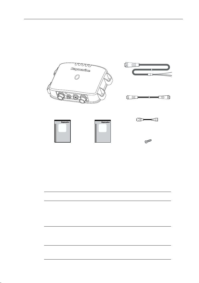
1.2 Unpacking and Inspecting the Components
Unpack your system carefully, to prevent damage to the equipment. Save the
carton and packing, in case you need to return the unit for service.
Check that you have all the correct system components:
Power Cable, 3m
part no. R69053
C Series Network Cable, 3m
Digital Sounder Module,
part no. E63069
DSM300
Installation
Manual
D7481-1
Installation Manual,
part no. 87048
DSM300
Operation
Manual
Operation Manual for PLUS
Displays, part no. 81249
part no. E65010
2
adapter, 4-pin to 3-pin
hsb
part no. R69081
Mounting Screws,
No.8 (x4)
A 3m-long cable is included for connecting your DSM300 to a C Series display.
Longer cables and connection cables for other types of systems must be
purchased separately. Select from the following:
Table 1-1: Cable Options
System Item Part No.
E Series
SeaTalkhs Network Cable, RJ-45, 1.5m
SeaTalkhs Network Cable, RJ-45, 5m
hs
SeaTalk
Network Cable, RJ-45, 10m
SeaTalkhs Network Cable, RJ-45, 20m
C Series C Series Network Cable, 4-pin-to-4-pin, 10m
DSM Cable, 4-pin-to-3-pin, 3m
DSM Cable, 4-pin-to-3-pin, 10m
2
hsb
PLUS Series
(Pathfinder)
hsb2 In Line Terminator
hsb2 Splitter Cable
E55049
E55050
E55051
E55052
E65011
E65009
E05016
R58117
E55040
Page 10

10 DSM300 Installation Manual
1.3 Selecting Sounder Module Mounting Location
The DSM300 is waterproof to IPX-7 is and is designed to be mounted either above
or below deck.
Mount the DSM300 where it is:
• protected from physical damage and excessive vibration
• protected from prolonged exposure to rain, salt spray and direct sunlight
• well ventilated
• as close to the transducer as possible
Do not locate the DSM300:
• in the engine compartment
• on the main console
When planning the installation, the following should be considered to ensure
reliable and trouble free operation:
•
Access: There must be sufficient space below the unit to enable cable con-
nections to the panel connectors, avoiding tight bends in the cable.
Interference: The selected location should be far enough away from
•
devices that may cause interference, such as motors, generators, and radio
transmitter/receivers. (See the EMC guidelines earlier in this chapter.)
•
Magnetic compass: Moun t the unit at least 3 ft (1 m) away from a magn etic
compass.
•
Cable runs: The unit must be located near a DC power source. The power
cable supplied is 10 ft (3 m).
•
Environment: Good ventilation is required to prevent the unit from over-
heating.
CAUTION: Do Not Remove the Transducer Cable
Removing the transducer cable from the DSM300 while power is
turned on can cause sparks. As with any electronic device, be sure
the sounder module is mounted where it is well ventilated and
free from gasoline fumes.
Page 11
Chapter 1: DSM300 Installation 11
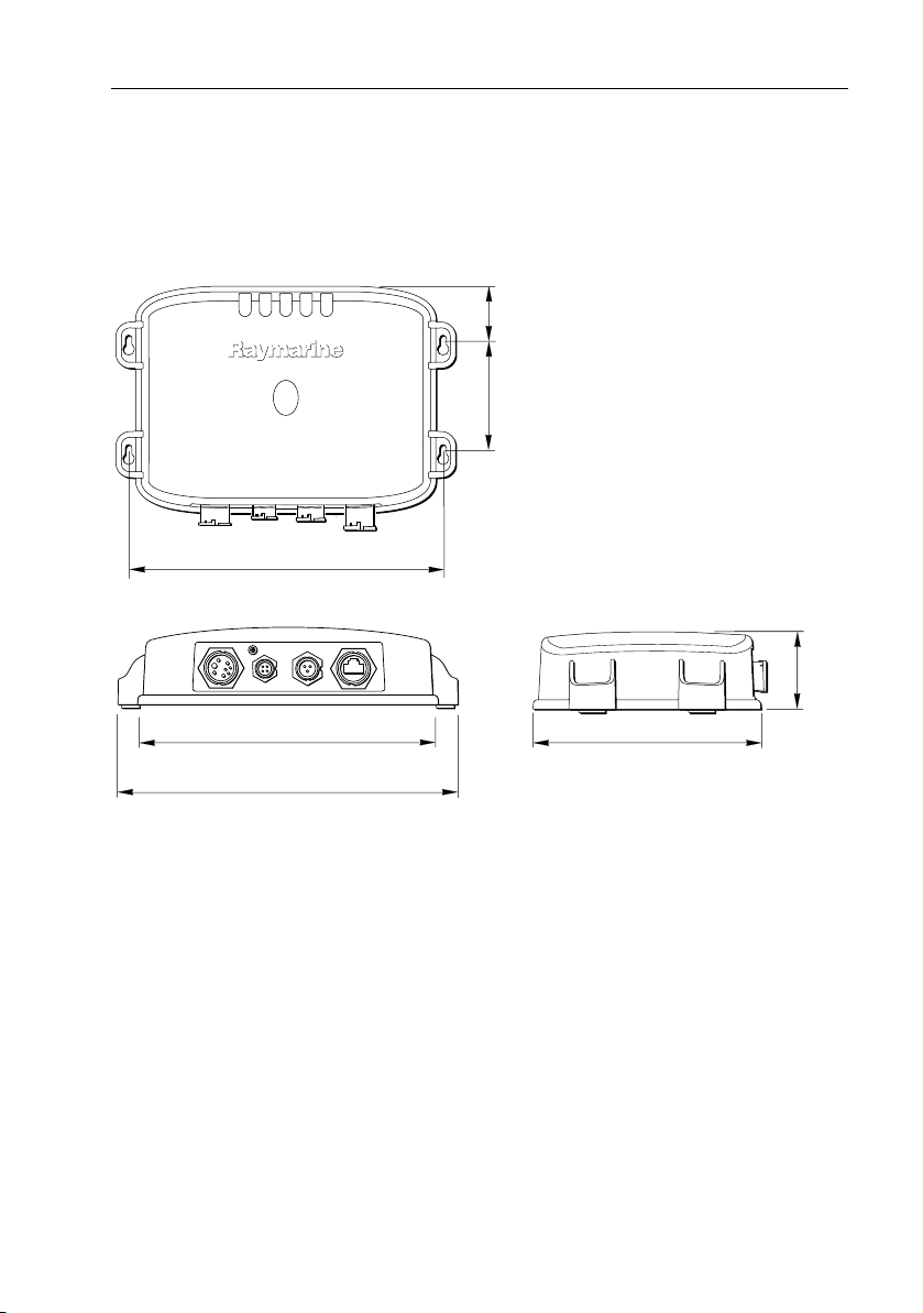
1.4 Mounting the Sounder Module
The DSM300 can be mounted either above or below deck using the supplied
hardware. To allow for ease of cable connection, mount the sounder module so
that the cables hang below the unit.
1.65 in
(41.8 mm)
3.46 in
(88 mm)
Weight: 2.2 lbs (1.0 Kg)
9.96 in (252.9 mm)
9.51 in (241.6 mm)
10.76 in (273.3 mm)
Figure 1-2: DSM300 Dimensions
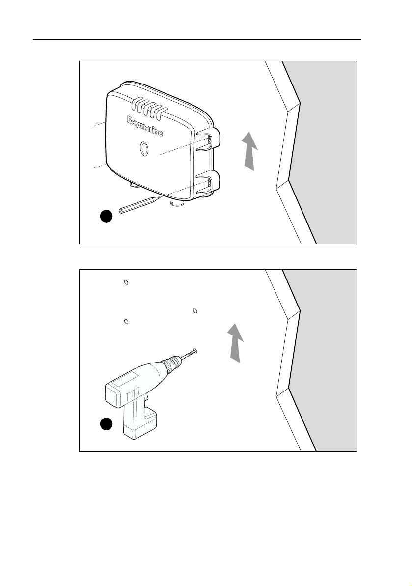
➤ To mount the DSM300:
1. Hold the module in the location where you want to mount it, making sure it is
perpendicular to the deck.
2. Mark the location of the four key holes onto the mounting surface.
Compass Safe Distance: 39 in (1 m)
D7468-1
7.37 in (187.2 mm)
2.43 in
(61.7 mm)
Page 12
12 DSM300 Installation Manual
Vertical
x4
D7479-1
3. Drill a 9/64" pilot hole at each of the marked locations.
Vertical
x4
D7538-1
Note:
For fiberglass wi th a gelcoat surface, you should overdrill the surface to prev ent the
gelcoat from chipping when driving in the screw. Before drilling the pilot hole, hand drill
the marked location with an oversized bit and countersink to approximately 3/8" diameter.
4. Drive the supplied #8 screws into the pilot holes. Screw them in about half way.
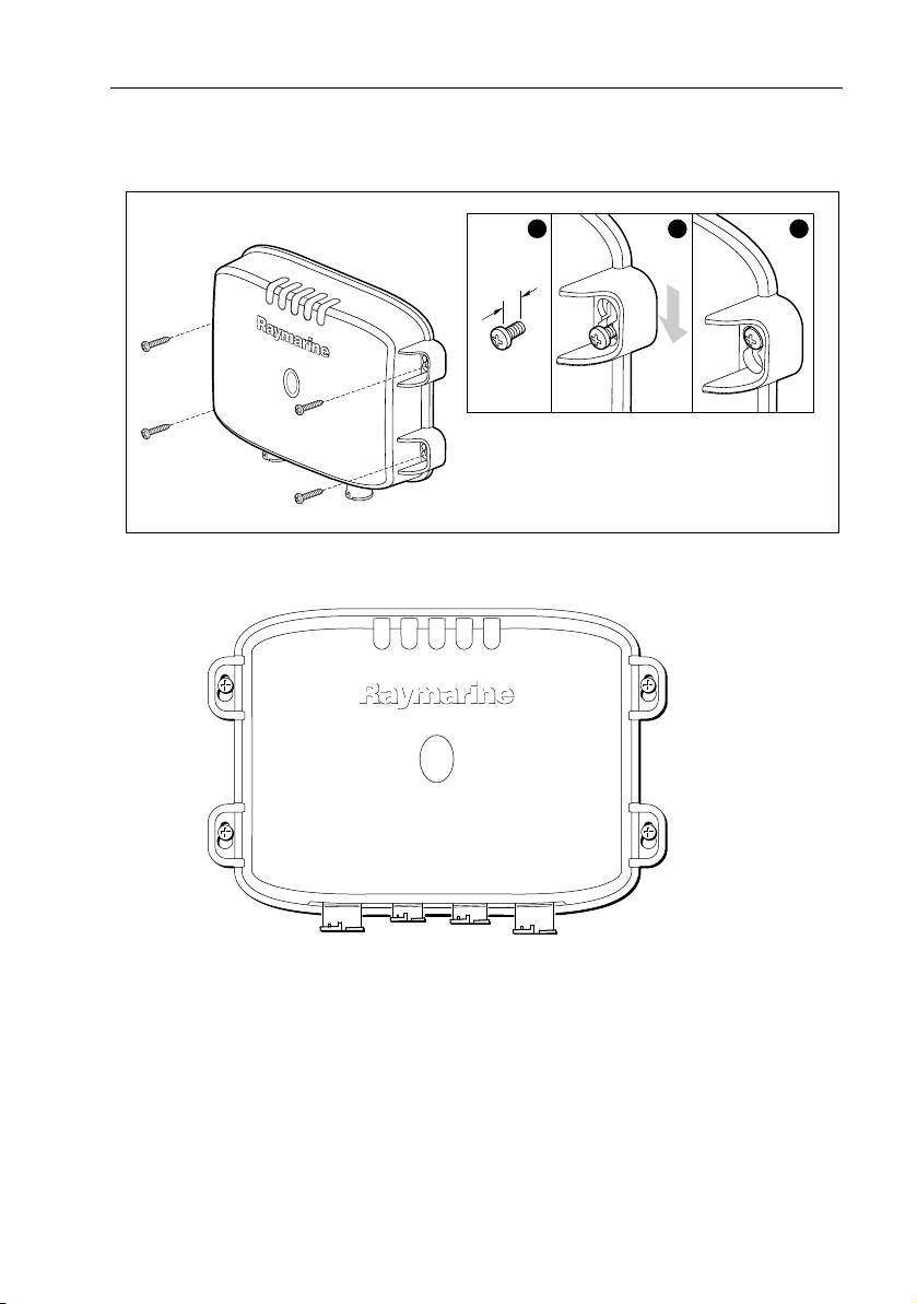
5. Mount the module to the surface, slipping the screw heads through the four
key holes.
Page 13
Chapter 1: DSM300 Installation 13
6. Press the module downward so the screws align with the narrow end of the
keyholes.
6 mm
minimum
7. Tighten the screws. Do not overtighten.
1
2
3
D7480-1
Figure 1-3: Properly Mounted DSM300
7469-1
Page 14

14 DSM300 Installation Manual
1.5 Cable Runs
Consider the following before installing the system cables:
• You will need to attach power, transducer, and display cables.
• All cables should be adequately secured, protected from physical damage,
and protected from exposure to heat.
• Avoid running cables through bilges or doorways, or close to moving or hot
objects.
• Avoid sharp bends.
• Use a watertight feed-through wherever a cable passes through an exposed
bulkhead or deckhead.
• Secure cables in place using tie-wraps or lacing twine. Coil any extra cable
and tie it out of the way.
You will need to run the following cables:
•
Power cable, supplied with the unit. This 10 ft (3 m) cable has a connector
plug at one end for connecting to the sounder module, and 3 wires at the other
end for connecting the power supply. The power cable may be extended by up
to 60 ft (20 m) using a wire gauge of AWG 12 or greater. The DSM300 is
intended for use on boat’s DC power systems rated from 10.7 V to 32 V.
•
Display cable, used to connect the DSM300 to a display unit. A 3m-long
cable is included for connecting to a C Series display. Connection cables for E
Series or hsb
be purchased separately. See Table 1-1 “Cable Options“ on page 9 for a list of
available display cables.
•
Trans ducer c able, supplied with the transducer. This 30 ft (10 m) cable has
a connector plug (with an outer nut that you must attach) at one end for the
sounder module or extension cable. Optional extension cables are listed in
Table 2-1 “Accessories“ on page 25.
2
PLUS (Pathfinder) Series displays, or longer C Series cables, must
CAUTION: Do Not Cut or Splice the Transducer Cable
• There is high voltage on the transducer cable. Splicing could
create a safety hazard.
• Cutting the transducer cable severely reduces sonar
performance. If the cable is cut, it must be replaced—it cannot
be repaired.
• Cutting the transducer cable will void the warranty and
invalidate the European CE mark.
Page 15
Chapter 1: DSM300 Installation 15
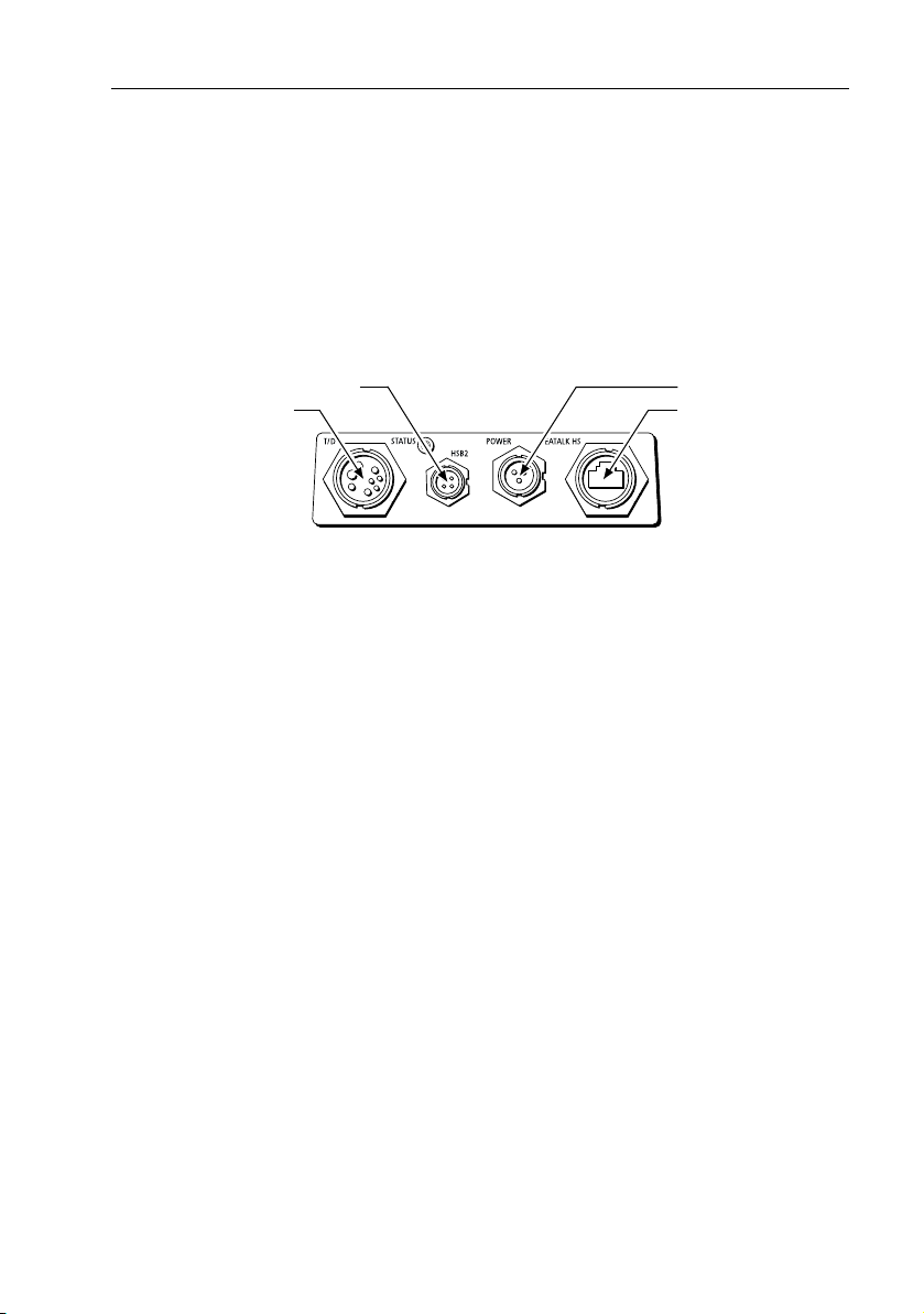
1.6 System Connections
The connector panel provides the following connection sockets:
T/D, 7-pin socket for connecting to the transducer
•
•
HSB2, 4-pin socket for connecting to a C Series or hsb
•
POWER, 3-pin socket for connecting to boat’s DC power systems rated from
10.7 V to 32 V and one RF ground (screen) connection
•
SEATALK HS, RJ-45 socket for connecting to an E Series display
C Series or hsb PLUS
Transducer
2
Figure 1-4: DSM300 Connector Panel
CAUTION:
To protect exposed pins, please place the attached dust cover
over the socket (4-pin or RJ-45) to which you are not connecting a
cable.
2
PLUS Series display
10.7 to 32 VDC
E Series Display
D7464-1
The following sections detail the connectors used when installing the DSM300.
DC Power Connection
The DSM300 is intended for use on boat’s DC power systems rated from 10.7 V to
32 V.
The power connection to the unit should be made at either the output of the
battery isolator switch or at a DC power distribution panel. Power should be fed
directly to the DSM300 via its own dedicated cable system and protected by a
thermal circuit breaker or fuse on the red (positive) wire that is installed close to
the power connection.
DC power is connected at the 3-pin POWER connector on the unit’s connector
panel. The connector (viewed from the outside) and pin functions are shown in
the following diagram and table.
Page 16

16 DSM300 Installation Manual
1
D6162-1
2
3
Figure 1-6: Power Connector
Pin No. Function Color
1 Battery positive (12/24/32 V systems) Red
2 Battery negative Black
3 Shield (drain wire) No insulation
The RED wire must be connected to the feed from the positive (+) battery terminal
and the BLACK wire to the feed from the negative (–) battery terminal. The shield
wire (drain) should be connected to the boat’s RF ground. See “Ground
Connection” on page 17.
Install a quick blow 8 amp fuse on the red (positive) wire.
CAUTION:
If the power connections are accidentally reversed the system
will not work. Use a multimeter to ensure that the input power
leads are connected for correct polarity.
There is no power switch on the DSM300. The unit turns on when the power cord
is attached to boat’s power and plugged into the POWER connector on the
connector panel.
Note:
You should locate the DSM300 so that the power cord can be easily removed, if
necessary. If the sounder is placed in a difficult-to-reach location, Raymarine strongly
suggests installing an on/off switch on the DSM300 power cord at a point where it is easily
accessible.
Page 17
Chapter 1: DSM300 Installation 17
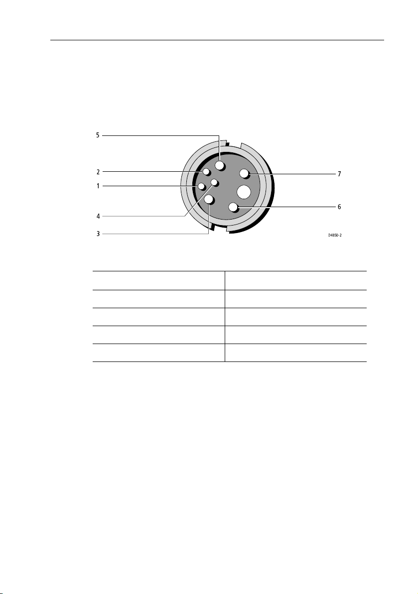
Transducer Connection
A 30 ft (10m) cable is supplied with the transducer. For details see “Tra ns du ce r
Cable” on page 26. The connector pins are shown in the following diagram,
together with the connections and wire colors; this is information is provided as
an aid to fault diagnosis.
5
2
1
4
3
7
6
D4850-2
Figure 1-7: DSM300 Transducer Connector
Pin No Function Color Pin No Function Color
1 Speed Red 5 Speed/Temp Ground Brown
2TempWhite 6+ Depth Blue
3ShieldDrain 7– Depth Black
4 Sense Green
Ground Connection
It is important that an effective RF ground is connected to the system. A single
ground point should be used for all equipment. You can ground the DSM300 by
connecting the drain wire (shield) of the Power Input cable to the boat’s RF
ground. If you need to extend the wire, the extension wire should be an 8 mm
braid or AWG 10 multi-stranded cable.
If your boat has a dedicated ground strap available, you can alternatively attach it
to the ground wing nu t on the rear panel of the module. If your boat do es not have
an RF system, connect the drain wire to the negative battery terminal.
The DC system should be either:
• Negative grounded, with the negative battery terminal connected to the
boat’s ground.
• Floating, with neither battery terminal connected to the boat’s ground.
Page 18
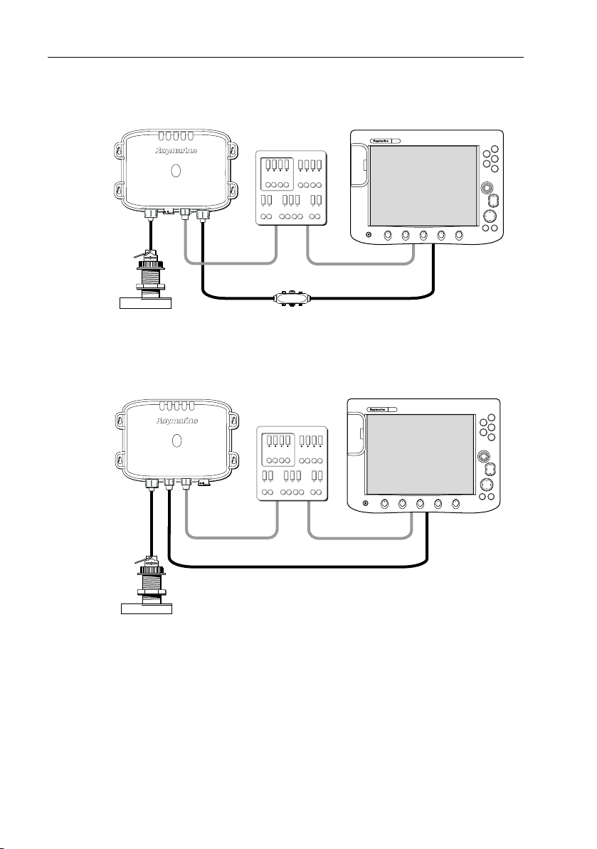
18 DSM300 Installation Manual
This system is not intended for use on “positive” ground vessels.
DSM300
not
used
Power Supply
E Series Display Unit
PAGE
ACTIVE
WPTS/
MOB
DATA
MENU
OUT
RANGE
IN
CANCELOK
D7467-1
Transducer
Crossover Coupler
Figure 1-8: Using the DSM300 with an E Series Display
Transducer
DSM300
not
used
Power Supply
Figure 1-9: Using the DSM300 with a C Series Display
C Series Display Unit
PAGE
ACTIVE
WPTS/
MOB
DATA
MENU
OUT
RANGE
IN
CANCELOK
D7466-1
Page 19
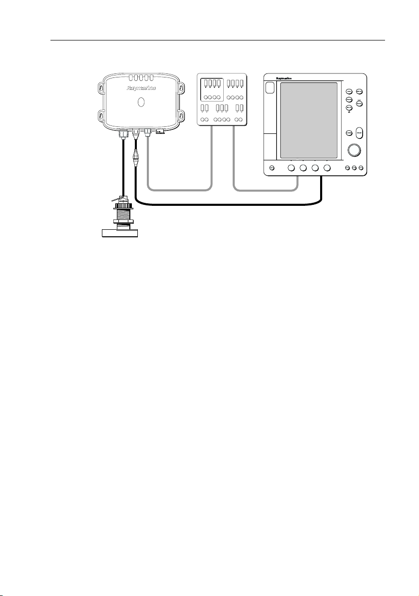
Chapter 1: DSM300 Installation 19
DSM300 hsb PLUS Series Display Unit
not
used
Power Supply
2
Transducer
Figure 1-10: Using the DSM300 with an hsb2 PLUS Series Display
D7606-1
Page 20
20 DSM300 Installation Manual
1.7 Configuration
How you configure your DNT300 depends on the type of display to which you will
be connecting it.
Configuring the DSM300 with E Series Displays
The E Series system operates on the SeaTalk
hs
network, which uses cables with an
RJ-45 modular connector. See Table 1-1 for a list of available E Series cables. When
the DSM300 is used with a single display, connection is made via a SeaTalk
Crossover Coupler.
E Series Display
SeaTalk
Crossover Coupler
hs
Cable
E55060
SeaTalk
DSM300
hs
Cable
D7593-1
Figure 1-11: Configuring an E Series System - Single Display
When used in a multiple display system, connect the DSM300 to the SeaTalk
Network Switch.
E Series Display
E Series Display
SeaTalk
hs
Network Switch
E55058
DSM300
hs
hs
SeaTalk
hs
Cable
SeaTalk
hs
Cable
SeaTalk
Figure 1-12: Configuring an E Series System - Multiple Displays
hs
D7602-1
Cable
Page 21
Chapter 1: DSM300 Installation 21
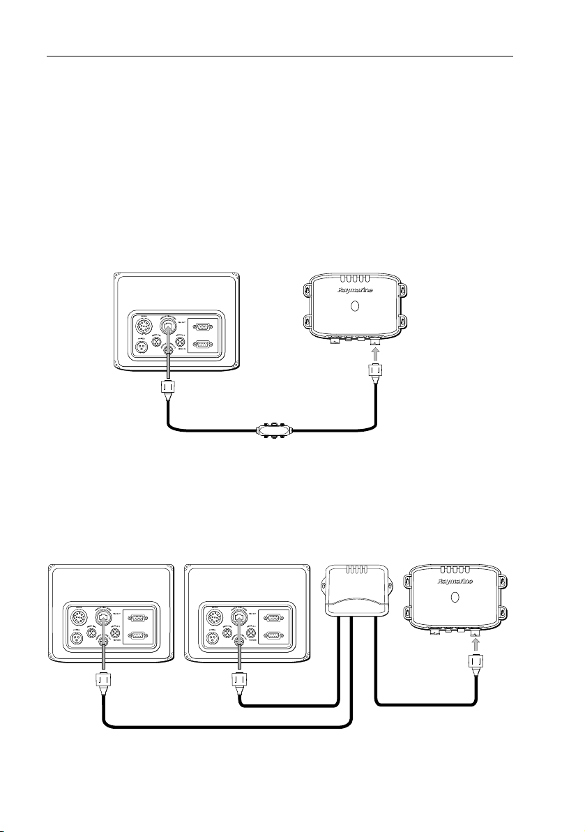
Configuring the DSM300 with C Series Displays
The C Series system uses cables with a round 4-pin twist-lock network connector.
A 3m-long C Series cable is included with your DSM300. If a longer cable is
required, an optional 10m C Series cable (part number E65011) is available from
Raymarine.
C Series Display
G
Y
R
K
2
L
K
A
L
T
A
A
T
E
A
S
E
S
R
R
A
E
D
A
W
R
O
P
M
S
D
T
A
U
E
/ O
M
IN
N
4-pin to 4-pin C Series Cable
DSM300
D7592-1
Figure 1-13: Configuring a New C Series System
The product that the DSM300 replaces—the DSM250 sounder module—has a
triangular 3-pin network connector. If you are replacing an old DSM250 with a
new DSM300 in an existing C Series network, you will need to install the supplied
4-pin to 3-pin hsb
2
adapter. Connect the 4-pin end of the adapter to the DSM300
and then connect the 3-pin end of the DSM cable to the DSM300.
Unlike the DSM250, however, the DSM300 network connection is internally
terminated. When replacing a DSM250 with a DSM300, DO NOT USE
the hsb
2
Inline Terminator that was connected to the DSM250.
DSM300
C Series Display
G
Y
R
2
LK
K
A
L
A
T
A
E
S
R
E
W
O
P
M
T
S
A
D
E
S
R
A
T
A
U
D
E
A
/ O
M
R
IN
N
R69081
4-pin to 3-pin hsb
adapter (supplied)
D7603-1
2
4-pin to 3-pin DSM cable
Figure 1-14: Replacing a DSM250 in an Existing C Series System
Page 22

22 DSM300 Installation Manual
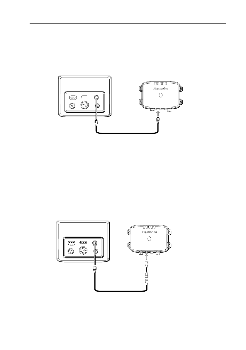
Configuring the DSM300 with hsb2 (Pathfinder) Series Displays
2
hsb
PLUS network cables have a triangular 3-pin connector on both ends. When
using the DSM300 with an hsb
3-pin hsb
The hsb
2
adapter between the DSM300 and the network cable.
2
system must be terminated at both ends of the network. If a PLUS Series
2
PLUS Series display, connect the supplied 4-pin to
display is the last device on the network, an inline terminator is installed on the
cable where it connects to the display. The network connection in the DSM300,
however, is internally terminated; it does not require an inline terminator.
Because the DSM300 is internally terminated, it must be installed
at the end of the hsb
terminator on the DSM300 end of the network. If an hsb
2
network. You must NOT use an inline
2
splitter is
used, you must connect it to a display and not to the DSM300.
R58117
2
PLUS Series Display
hsb
NMEA OUT
POWER/NMEA
HSB
2
hsb
Terminator
GRY
SeaTalk
TRANSDUCER
Inline
3-pin to 3-pin hsb2 cable
R69081
DSM300
4-pin to 3-pin hsb
adapter (supplied)
D7594-1
2
Figure 1-15: Installing a DSM300 in the hsb2 PLUS System - Single Display
2
hsb
PLUS Series Display
NMEA OUT
POWER/NMEA
HSB
TRANSDUCER
2
hsb
PLUS Series Display
GRY
SeaTalk
NMEA OUT
HSB
POWER/NMEA
TRANSDUCER
GRY
SeaTalk
DSM300
D7604-1
R58117
hsb
Terminator
3-pin hsb
2
cable
R55040
2
hsb
Splitter
3-pin hsb
2
cable
R69081
2
Inline
Figure 1-16: Installing a DSM300 in the hsb2 PLUS System - Multiple Displays
4-pin to 3-pin hsb
adapter (supplied)
2
Page 23

Chapter 2: Transducer Installation 23
Chapter 2: Transducer Installation
Transducers enable fishfinder systems to display depth, water temperature and/or
speed information, depending on the type of transducer(s) installed. This chapter
describes the transducers that are available for use with the DSM300.
This chapter also provides general information for installing the three main types
of transducers: transom mount, thru-hull and in-hull. Specific instructions for
installing your particular model are included with your transducer.
2.1 Selecting the Correct Type of Transducer
Before you start the installation, check that you have the correct transducer for
your application.
Applications
Transom Mount Transducers are recommended for personal watercraft and
powerboats with outboard, inboard-outboard and jet drives. They are NOT
recommended for large or twin screw inboard boats.
• Adjusts to transom angles from 3
tapered plastic, wood or metal shim will be needed.
• Designed for operation from 5 – 58 m.p.h. (4 – 50 knots).
Thru-Hull Transducers are recommended for boats with straight-shaft inboard
engines.
In-Hull Transducers are recommended for fiberglass hulls, especially in high
speed power boats and racing sailboats.
° – 16°. For angles greater than 16°, a
Materials
Plastic housings are recommended for fiberglass or metal hulls.
Bronze housings are recommended for wood or fiberglass hulls.
Stainless Steel housings are recommended for steel or aluminum hulls.
Notes: (1)
Installation of a bronze housing in a metal hull requires using of a fairing,
available from your Raymarine dealer.
(2)
Never install a metal housing in a vessel with a positive ground system.
Page 24

24 DSM300 Installation Manual
The DSM300 can be used with any of the following transducers:
Mounting
Method
Tra ns om
Part No.
(Model)
E66049
(M260)
E66078
(M256)
1, 2
3
Sensor
Type Material
Max.
Power
Depth Cast Urethane 1000W
Depth Cast Urethane 1000W
E66019
(ST69)
E66054
(P66)
Thru-Hull E66013
(P319)
E66014
(B117)
E66015
(SS555)
E66076
(R99)
E66024
(B256)
E66033
(B260)
E66053
(SS560)
E66018
(ST600/B120)
Speed,
Plastic 600 W
Temp
Depth,
Plastic 600W
Speed,
Temp
Depth Plastic 600 W
Depth Bronze 600 W
Depth Stainless Steel 600 W
4
5
5
4
Depth Cast Urethane 2000W
Depth,
Temp
Depth,
Temp
Depth,
Bronze 600 W or
1000 W
Bronze 600 W or
1000 W
Stainless Steel 1000W
Temp
Speed,
Bronze 600 W
Temp
E66030
(ST600/P120)
4
E66056
(B744V)
Speed,
Temp
Depth,
Speed,
Temp
Plastic 600 W
Bronze 600 W
Page 25

Chapter 2: Transducer Installation 25
Mounting
Method
Part No.
(Model)
E66057
(B744VL)
Sensor
Type Material
4
Depth,
Bronze 600 W
Max.
Power
Speed,
Tem p
In-Hull E66008
Depth Plastic 600 W
(P79)
E66049
1
Depth Cast Urethane 1000W
(M260)
E66075
Depth Cast Urethane 2000W
(R199)
1
Can be used In-Hull or Transom mounted
2
Requires E66047 kit to complete transom mount installation
3
Includes transom mounting kit
4
Includes high-speed fairing
5
Must be installed with a high-speed fairing (sold separately)
Accessories
The following optional equipment is also available from Raymarine for your
transducer:
Table 2-1: Accessories
Item Part No. For Use With
Transducer Extension Cable, 10 ft (3 m)
Transducer Extension Cable, 18 ft (5 m)
Trans du cer Y-C ab le
High Speed Fairing E66023
E66009
E66010
E66022
E66025
E66034
Depth Transducers
Depth Transducers
Spe ed /Temp Tra ns ducers
E66056(B744V), E66057(B744VL)
E66024 (B256)
E66033 (B260)
In-Hull Mounting Kit
Transom Mounting Kit
Notes: (1)
To ensure proper alignment and a secure fit, many thru-hull transducers
require a fairing for installation. In addition to improving sounder performance at all speeds, the fairing allows better fitting to the hull and dramatically increases the sealing surface.
(2)
This information was current as of the date this handbook was printed.
New transducer models are constantly becoming available. Check with
your dealer for the most current list.
E66050
E66047
E66049 (M260)
E66049 (M260), E66046 (M256)
Page 26

26 DSM300 Installation Manual
2.2 Transducer Cable
A 30 ft (10m) cable is supplied with the transducer. The transducer cable may be
extended up to a maximum of 60 ft (20 m) using optional extension cables.
The transducer cable connector has a nut that has been removed to aid
installation. To allow you to complete the installation without cutting the cable,
ensure that any holes you drill are large enough to accept the connector, with the
nut removed.
After the cable has been run through the holes, this nut must be attached before
the cable can be connected, as described in
CAUTION: Do Not Splice the Cable
Do not cut the transducer cable or remove the connector. Do not
try to shorten or splice the cable. If the cable is cut, it cannot be
repaired. Cutting the cable will also void the warranty.
• For a Transom mount installation – route the cable up and over the top edge
of the transom as shown in Figure 2-2 . Secure the cable using cable clamps
(available from your local marine equipment supplier).
If you do not want to expose the cable on deck, you may drill a hole 13/16"
(21 mm) through the transom for the cable (with connector attached). To
seal the opening, use a feed-thru cap where the cable passes through the
transom.
• For either type of installation – run the cable through the interior of the boat.
• If the 30 ft (10 m) cable is not long enough, extension cables are available
from your Raymarine dealer. See Table 2-1 on page 25. Total cable length from
the transducer to the DSM must not exceed 60 ft (20 m). When you attach the
extension cable, be sure that the connections are watertight. Use Dow Corning DC-4 or an equivalent sealing compound to protect the connector assemblies.
CAUTION:
Do not pull on the cable as this can damage the transducer wires.
Transducer Cable Connections
.
Transducer Cable Connections
The transducer cable connector (and Y-connector, if supplied) has a nut that has
been removed to aid installation. To allow you to complete the installation
without cutting the cable, ensure that any holes you drill are large enough to
accept the connector, with the nut removed (approximately 13/16" or 21mm).
Page 27

Chapter 2: Transducer Installation 27
Before attaching the transducer cable, you will need to attach the connector nut
and split ring. These items, plus a wedge tool, are included in the transducer
packaging.
Connector/cable
Protrusion
Mounting groove
Nut
Split
Split ring
Wedge tool
D5256-1
Figure 2-1: Assembling the Transducer Connector
➤ To attach the transducer cable connector:
1. Slip the nut over the connector cable end. Push it past the connector and over
the cable.
2. Insert the wedge tool into the groove in the split of the split ring and slide the
wedge tool until its squared end is flush with the larger edge of the split ring.
3. Slip the split ring and wedge tool over the connector body until aligned with
the mounting groove on the connector.
4. Remove the wedge tool and seat the split ring in the mounting groove, making sure the connector protrusion falls into the split.
5. Slip the nut forward until it stops. Twist until the protrusions on the inside of
the nut align with the grooves on the split ring.
6. Slip the nut forward and snap into place.
Page 28

28 DSM300 Installation Manual
The transducer cable is attached to the 7 pin male connector on the DSM. How
you connect the cable to the unit depends on the type of transducer you have
installed:
•
Combined depth/speed/temp transducers have a 7 pin female connec-
tor. Attach the transducer cable connector directly to the sounder module.
•
Combined speed/temperature transducers have a 3 pin female con-
nector that requires the use of an additional Y-shaped cable (Raymarine part
number E66022) to attach to the 7 pin connector on the DSM300. This Y-cable
is included with your speed/temperature transducer.
Attach the 7 pin female connector on the Y-cable to the sounder module, and
then attach the transducer cable to the 3 pin male connector on the Y-cable.
•
Depth-only transducers have a 7 pin female connector.
Attach the transducer cable connector directly to the sounder module.
If being installed in conjunction with a speed/temperature transducer, attach
the Y-cable’s 7 pin female connector to the sounder module, and then attach
the transducer cable to the 7 pin male connector on the Y-cable.
Note:
If your syste m requires both a Y-cab le and a transducer extens ion cable, ensure that
you connect the Y-cable to the sounder module and the extension cable to the transducer.
CAUTION: Do not cut or splice the transducer cable:
• There is high voltage on the transducer cable. Splicing could
create a safety hazard.
• Cutting the transducer cable severely reduces sonar performance. If the cable is cut it must be replaced, not repaired.
• Cutting the transducer cable will void the warranty and invalidate the CE mark.
CAUTION: Removing the Transducer Cable
Removing the transducer cable from the rear of the DSM300 while the sounder
module is powered on can cause sparks. Only remove the transducer cable after
power has been removed from the DSM300.
If the transducer cable is accidentally removed while the DSM300 is powered on,
remove power from the sounder module, replace the transducer cable, and then
return power to the module. As a safety feature, the DSM300 only recognizes that
the transducer is connected at power-up.
Page 29

Chapter 2: Transducer Installation 29
Cable cover
Cable clamps
2 in (50 mm)
D5033-2
Figure 2-2: Installing the Cable on a Transom Mount Transducer
2.3 Selecting the Equipment Location
Transducer Mounting Location
It is very important that you mount the transducer correctly. The transducer
provides the most reliable readings if it looks into water that is smooth and
undisturbed.
Acoustic noise is always present and these sound waves can interfere with the
operation of the transducer. Ambient (background) noise from sources such as
waves, fish, rain and other vessels cannot be controlled. Carefully selecting the
transducer’s mounting location can minimize noise generated by the vessel’s
propeller(s), shaft(s), machinery, and other echo sounders. The lower the noise
level, the higher the echo sounder gain that can be used, and the better the
sounder’s performance.
Page 30

30 DSM300 Installation Manual
To ensure accurate readings, DO NOT mount the transducer in an
area of turbulence or bubbles:
• near water intake or discharge openings
• behind strakes, fittings or hull irregularities
• behind eroding paint (an indication of turbulence)
Choose a location where:
• The water flowing across the hull is smoothest with a minimum of turbulence
and bubbles (especially at high speeds).
• The transducer will be continuously covered by water when the boat is moving. If the transducer is mounted near the side of the boat, it may be exposed
when the boat is turning.
• The transducer beam is unobstructed by the keel or propeller shaft.
• There is a minimum deadrise angle.
• There is adequate headroom inside the vessel for the height of the thru-hull
housing, tightening the nuts, and removing the valve assembly insert.
Transom Mount Transducer
• Single drive boat – Refer to Figure 2-3 . If your boat has one propeller (out-
board or inboard), mount the transducer about 18" (455 mm) to the side of
the boat’s centerline. To reduce any interference caused by air bubbles,
choose the side on the downstroke of the propeller (usually the starboard
side).
• Twin drive boat – If your boat has twin propellers (outboard or inboard-out-
board), mount the transducer between the drives near the centerline of the
boat. If the boat will be operated at high speeds, the transducer may be
mounted closer to the centerline of the hull.
• If the propeller can be turned to steer the boat, allow at least 2" (50 mm)
beyond the swing radius of the propeller. This will prevent the propeller from
damaging the transducer when it is turned.
Page 31

Chapter 2: Transducer Installation 31
Approximately 18 in (457 mm) clearance
Be sure to allow at
least 2 in (50 mm)
beyond the swing radius
of the propeller
D4871-2
Figure 2-3: Transom Mount Transducer Location
• Do not mount the transducer behind any hull fittings, intakes or other parts
extending from the hull that may cause turbulence or air bubbles.
• The bracket has a quick-release mechanism, shown Figure 2-4 . This allows
the transducer to flip up if it hits any debris or the bottom. Allow enough clearance above the transducer for it to swing upwards completely – this is about
10" (254 mm), measured from the bottom of the transom.
Allow a clearance of
at least 254 mm (10 in)
Figure 2-4: Transom Mount Transducer - Quick-release Bracket
Transducer in
released position
D4872-2
Page 32

32 DSM300 Installation Manual
• On a boat with a fiberglass hull, the leading edge of the transducer should
extend 1/8" (3.2 mm) to 1/4" (6 mm) below the bottom edge of the hull as
shown in Figure 2-5 . On an aluminum hull, the transduce r should extend a bit
more – 1/4" (6 mm) to 3/8" (9 mm)
• If the boat will be trailered, be sure the transducer will not hit any rollers,
bunks or fittings on the trailer.
Average transom angle -
no wedge necessary
Vertical transom -
place wedge this way
Sloping transom -
place wedge this way
2° to 5°
The bow of the transducer
is above the bottom of the
transom, creating cavitation.
For fibreglass hull 1/8 to 1/4 in (3.2 to 6 mm)
For aluminium hull 1/4 to 3/8 in (6 to 9 mm)
2° to 5°
Rivets on the hull are
creating bubbles. Lower
the transducer a bit.
Figure 2-5: Transom Mount Transducer - Vertical Position
Thru-hull Transducer and In-hull Transducer
Similar consideration should be given to the location of thru-hull and in-hull
transducers. Figure 2-6 shows the best transducer location for different hull types.
• Displacement hull powerboat – Locate at 1/3 aft load waterline length (LWL)
and 6 - 12" (150-300 mm) off the centerline on the side of the hull where the
propeller is moving downward.
• Planing hull powerboat – Mount well aft, on or near the centerline, and well
inboard of the first set of lifting strakes to ensure that it is in contact with the
water at high speeds. Mount on the side of the hull where the propeller is
moving downward.
2° to 5°
No!No!No!
The rear of the transducer
is too high, creating
cavitation.
D4873-2
Page 33

Chapter 2: Transducer Installation 33
Outboard and I/O – Mount just forward of the engine(s).
Inboard – mount well forward of the propeller(s) and shaft(s).
Step-hull – Mount just ahead of the first step.
Boats capable of speeds above 25 kn (29 m.p.h.) – Review transducer location
and operating results of similar boats before proceeding.
• Fin keel sailboats – Mount to the side of the centerline and forward of the fin
keel 1 - 2 ft (300-600 mm).
• Full keel sailboats – Locate amidships and away from the keel at the point of
minimum deadrise angle.
• Fiberglass Hulls – Since the hull absorbs acoustic energy, transmitting through
the hull reduces the sensor’s performance. Fiberglass hulls are often reinforced in places for added strength. These cored areas contain balsa wood or
structural foam, which are poor sound conductors. If you cannot avoid locating the sensor over coring, follow the instructions for “Installation in a Cored
Fiberglass Hull” on page 55.
• Thru-hull Transducer Headroom– Allow adequate headroom inside the vessel
for the height of the thru-hull housing, tightening the nuts and removing the
insert. The minimum headrooms are:
With fairing: 10" (254 mm)
Without fairing: 12" (305 mm)
• In-hull Transducer – Find a location where the fiberglass is solid:
There are no air bubbles trapped in the fiberglass resin.
There is no coring, flotation material, or dead air space sandwiched between
the inside skin and the outer skin of the hull.
Page 34

34 DSM300 Installation Manual
Displacement hull
Pressure waves
1/3 Aft
Load waterline length (LWL)
Planning hulls
Outboard and I/O
Full keel sailboat
Step hull Fin keel sailboat
Inboard
6--12in
(150 -- 300 mm)
D4857-2
Figure 2-6: Best Location for Thru Hull Transducer
Page 35

Chapter 2: Transducer Installation 35
2.4 Installing the Transom Mount Transducer
Preparation
Transducer Mounting Bracket
When installed, the lower surface of the transducer should tilt down toward the
rear at a slight angle (2° to 5°). The mounting bracket includes a wedge;
depending on the angle of the transom on your boat, you may need to install this
wedge to get the correct transducer angle.
1. To attach the transducer to the bracket, insert the transducer mounting lugs
into the slot in the bracket as shown in Figure 2-7 .
Correct Incorrect
Attach the two parts Bracket is installed
Lower the transducer and
snap in the release clip
upside down
D4874-2
Figure 2-7: Fitting the Transducer to the Bracket
2. Looking at the rear of the boat, be sure the bracket is vertical (perpendicular
to the water line) and hold the bracket (plus the wedge, if used) against the
transom.
Trace the position of the screw slots, then mark the screw positions as shown
in Figure 2-8 . The outer two screws should be placed about 1/4" (6 mm) up
from the bottom of each slot, the center screw should be placed about 1/4" (6
mm) down from the top. This will allow the bracket to be adjusted up or down.
Remove the bracket.
Page 36

36 DSM300 Installation Manual
Correct alignment
Insert screws 1 and 3, 6.4 mm (1/4 in)
from the bottom of the slots, and
screw 2, 6.4 mm (1/4 in) from the top
the slot to allow room for adjustment.
Incorrect alignment
If screws are inserted this way it
won't be possible to make the
height adjustment.
1
23
123
D4875-2
Figure 2-8: Position of Screws in Mounting Bracket
Installation
1. On a fiberglass hull, to minimize surface cracking of the gel coat: Before drilling the pilot holes, use a 1/4" (6 mm) drill bit to drill a shallow hole (chamfer)
at each location about 1/16" (1.5 mm) deep.
Drill pilot holes 3/4" (19 mm) deep using a 9/64" (3.6 mm) drill bit.
To prevent drilling too deeply, wrap masking tape around the drill bit about
7/8" (22 mm) from the tip. Drill in only as far as the tape.
2. Apply a good quality marine sealant to the pilot holes to protect the hull from
water penetration.
3. Attach the bracket to the hull using the panhead screws with flat washers. Do
not completely tighten the screws yet.
4. Move the bracket up or down so the leading edge of the transducer has the
clearance shown in Figure 2-5 .
5. Once the bracket is in the correct position tighten the screws.
2.5 Installing the Thru-hull Transducer
Tools and Material Needed
Water-based antifouling paint (mandatory for boats kept in salt water)
Safety goggles
Dust mask
Electric drill
Drill bit: 1/8" (3 mm)
Page 37

Chapter 2: Transducer Installation 37
Hole saw:
Fiberglass or wood Drill 2" (51 mm)
Aluminium or steel hull Drill 2-1/8" (54 mm)
Sandpaper
File (for installation in a metal hull)
Mild household detergent or weak solvent (alcohol)
Marine sealant
Slip-joint pliers
Silicone grease or petroleum jelly
Tie-wraps
Cored fiberglass hull installation:
Hole saw for hull interior 2-3/8" (60 mm)
Cylinder, wax, tape and casting epoxy
Fairing;
Level and protractor (installation with a fairing)
Rasp (installation with a fairing)
Preparation
Fairing
Most vessels have a deadrise angle at the transducer’s mounting location. If the
transducer is mounted directly to the hull, the sonar beam will be tilted off-vertical
at the same angle as the deadrise. To offset this deadrise angle, you can install a
transducer fairing. Different fairings are available to fit various transducers.
CAUTION: Using a Fairing
If thru-hull transducers are not carefully installed and fitted to the
shape of the hull, the vessel may take on water. To ensure proper
alignment and a secure fit, these transducer models MUST be
installed with a fairing. In addition to improving sounder
performance at all speeds, the fairing allows better fitting to the
hull and dramatically increases the sealing surface.
Fairings are also strongly recommended for use with other high performance
transducers. See the table that follows.
The fairing is used to:
• Vertically orient the sound beam by mounting the transducer parallel to the
water surface
• Minimize aerated water flowing over the transducer’s face by mounting it in
deeper water
• Reduce drag by directing the water around the multisensor
Page 38

38 DSM300 Installation Manual
The fairing is made of high impact urethane with an integrated cutting guide. It
can be shaped to accommodate a deadrise angle of up to 25° and a range of hull
thicknesses as follows:
Fairing
No.
Used with Transducer
No. (model)
Max. Hull Thickness
with Fairing
E66023 E66056 (B744V)
E66023 E66057 (B744VL)
E66025 E66024 (B256)
E66034 E66033 (B260)
" (26mm)
1
" (87mm)
3-3/4
" (45mm)
1-3/4
" (45mm)
1-3/4
Aft View
Backing block
minimum fairing
thickness
D5568-1
Hull
Slope of hull
Deadrise angle
Parallel to
water surface
Fairing
Isolation sleeve
Figure 2-9: Deadrise Angle and Fairing Thickness
Backing Block
A backing block is used inside the hull to provide a level surface for the hull nut to
seat against (see Figure 2-9 ). After cutting the fairing, use the remaining section
with the cutting guide as the backing block (see Figure 2-10 ).
Page 39

Chapter 2: Transducer Installation 39
⇐
BOW
Cutting guide
Triangular recess
for anti-rotation bolt
D5567-1
Figure 2-10: Transducer Fairing
Cutting the Fairing
1. Measure the deadrise angle of the hull at the selected location using a digital
level, or bubble level and protractor (see Figure 2-9 ).
2. Tilt the band saw table to the measured angle and secure the cutting fence
(see Figure 2-11 ).
Band saw table
Cutting guide
Deadrise
angle
Bow end for
installation
on port side
Figure 2-11: Cutting the Fairing
Fence
D4860-2
Page 40

40 DSM300 Installation Manual
CAUTION:
The arrow on the fairing always points forward towards the bow.
Be sure to orient the fairing on the band saw so the angle cut
matches the intended side of the hull.
3. Place the fairing on the table so the cutting guide rests against the fence. The
arrow/blunt end will point toward you for installation on the port side and
away from you for installation on the starboard side of the boat.
CAUTION:
Always wear safety goggles and a dust mask when drilling.
4. Recheck steps 1 through 3, then cut the fairing.
5. Shape the fairing to the hull as precisely as possible with a rasp or power tool.
Antifouling Paint
Marine growth can accumulate rapidly on the transducer’s surface, reducing
performance in weeks. Surfaces exposed to salt water must be coated with
antifouling paint.
Use water-based antifouling paint only.
Never use ketone-based paint since ketones can attack many
plastics, possibly damaging the transducer.
Reapply paint every six months or at the beginning of each boating season.
It is easier to apply antifouling paint before installation, but allow sufficient drying
time. As illustrated in Figure 2-12 , paint the following surfaces:
Exposed area of the housing, including the acoustic window
Bore of the housing up to 1-1/4" (30 mm)
Outside wall below lower O-ring
Exposed end of the paddle wheel insert
Paddle wheel cavity
Paddle wheel
Blanking plug below the lower O-ring and the exposed end
Page 41

Chapter 2: Transducer Installation 41
Housing Paddlewheel
Paint exposed housing
and bore up to 1.1/4" (30 mm)
Paint outside wall below the lower 'O' ring including
exposed end, paddlewheel cavity and paddlewheel
insert
Lower
'O' ring
D4859-2
Figure 2-12: Applying Antifouling Paint
Installation
Note:
To install the thru-hull transducer in a cored fiberglass hull, follow the instructions
in Installation in a Cored Fiberglass Hull on page 48.
Drilling Holes
CAUTION:
Always wear safety goggles and a dust mask when drilling.
1. Drill a 1/8" (3 mm) pilot hole perpendicular to the water line from inside the
hull (see Figure 2-9 ).
If there is a rib or strut near the mounting location, drill from the outside.
If the pilot hole is drilled in the wrong location, drill a second hole in a better
location. Apply masking tape to the outside of the hull over the incorrect hole
and fill it with epoxy.
Page 42

42 DSM300 Installation Manual
2. Cut a hole from outside the hull:
Fiberglass or wood hull – Use a 2" (51 mm) hole saw.
Aluminium or steel hull – Use a 2-1/8" (54 mm) hole saw to accommodate the
isolation sleeve used to prevent contact between the stainless steel housing
and the metal hull.
3. Sand and clean the area around the hole, inside and outside, to ensure that
the sealant will adhere properly to the hull. If there is any petroleum residue
inside the hull, remove it with either a mild household detergent or a weak
solvent (alcohol) before sanding.
4. Remove one safety ring, the retaining pin, the cap nut, and the hull nut from
the transducer (see Figure 2-13 ).
Retaining pin
Safety ring
Cap nut
Stem
Hull nut
Backing
block
Hull
Fairing
Marine
sealant
D5566-1
Figure 2-13: Seating
Dry Fit for Fairing
CAUTION:
If a fairing is used, the anti-rotation bolt must be installed to
prevent the fairing from rotating when the boat is underway.
1. Dry fit the transducer to locate the hole for the anti-rotation bolt.
2. Thread the transducer cable through the large hole in the fairing and through
the mounting hole in the hull. Seat the transducer firmly in the recess in the
fairing.
Note:
The transducer must be flush with the fairing. If it is recessed more than 1/64"
(0.5mm) inside the fairing, you may carefully file or sand the fairing flush with the transducer.
Page 43

Chapter 2: Transducer Installation 43
CAUTION:
Always wear safety goggles and a dust mask.
3. Attach the drill bit to your drill appropriate for your fairing:
Fairing Used with Transducer Drill Size
E66023 E66056 (B744V),
3/8
" (10mm)
E66057 (B744VL)
E66025 E66024 (B256)
E66034 E66033 (B260)
" (13mm)
1/2
" (13mm)
1/2
4. Slide the transducer’s stem with the fairing in place into the mounting hole. Be
sure the triangular recess in the fairing is pointing forward toward the bow.
5. While holding the assembly in place and using the bolt hole in the fairing as
your guide, drill a hole through the hull for the anti-rotation bolt.
6. Remove the assembly and cable from the mounting hole.
7. Sand and clean the area around the hole, inside and outside, to ensure that
the sealant will adhere properly to the hull.
Metal hull - Remove any burrs around both holes with a file and sandpaper.
BOW
Anti-rotation
bolt
⇐
Nut and
washer
Triangular plug
with curved surface
facing outward
Backing
block
D5565-1
Fairing
Figure 2-14: Using a Fairing and Backing Block
Seating
1. Remove the transducer from the fairing, if used.
2. Stainless steel transducer in metal hull - Slide the appropriate size isolation
sleeve over the cable and onto the stem of the transducer as far down as possible (see Figure 2-9 ).
Page 44

44 DSM300 Installation Manual
Be sure the top of the isolation sleeve will be below the top of the backing
block to prevent the sleeving from interfering with tightening the hull nut.
CAUTION:
To prevent electrolytic corrosion, never allow direct contact
between a stainless steel transducer and a metal hull.
3. Apply a 1/16" (2mm) thick layer of marine sealant to the sides of the transducer that will contact the fairing, if used, and up the stem 1/4" (6mm) higher
than the combined thickness of the fairing, hull, backing block, and hull nut.
This will ensure there is marine sealant in the threads to seal the hull and hold
the hull nut securely in place (see Figure 2-13 ).
Stainless steel transducer in metal hull - Apply the marine sealant to the outside of the sleeving instead of the stem itself.
4. If a fairing is used, thread the transducer cable through the fairing and seat
the transducer firmly within the recess in the fairing.
5. Apply a 1/16" (2mm) thick layer of marine sealant to the surface of the fairing
that will contact the hull, if used.
Attaching the Transducer
1. From outside the hull, thread the cable through the mounting hole.
2. Push the stem of the transducer (with the fairing in place) into the mounting
hole using a twisting motion to squeeze out excess sealant.
3. From inside the hull, slide the backing block onto the transducer cable and
stem, seating it firmly against the hull (Figure 2-15 ).
CAUTION:
Be careful to avoid cross threading the cap nut.
4. Screw the hull nut in place and tighten it with slip-joint pliers.
Stainless steel transducer in metal hull - Be sure the top of the isolation sleeve
is below the top of the backing block to prevent the sleeving from interfering
with tightening the hull nut.
5. Apply a 1/16" (2mm) thick layer of marine sealant to the anti- rotation bolt,
1/4" (6mm) higher than the combined thickness of the fairing, hull, backing
block, washer, and nut. This will ensure that there is marine sealant on the
threads to seal the hull and hold the nut securely in place (see Figure 2-14 ).
6. Push the bolt through the fairing, if used, and into the hull.
7. From inside the hull, slide the washer and nut onto the bolt. Screw the nut in
place and tighten it with slip-joint pliers.
Wood hull - Allow for the wood to swell.
Page 45

Chapter 2: Transducer Installation 45
Cable
Safety chain
Pull ring
Safety ring
Cap nut
Stem
Backing block
D4863-2
Retaining pin
Safety wire
Hull nut
Hull
Fairing
Transducer
Figure 2-15: Fore View of Transducer Installation
8. If a fairing is used, apply marine sealant to the flat side of the triangular plug.
Push the plug into the triangular recess in the fairing. The triangular plug fits
one way only. Be sure the curved side of the plug is exposed, matching the
curve on the outside of the fairing. Tap it into place with a mallet.
CAUTION:
For smooth water flow over the transducer’s sensor, be sure that
the external surface of the installed triangular plug is FLUSH with
the external curved surface of the fairing.
9. Being sure the valve assembly is seated firmly in the housing, carefully screw
the cap nut in place. Hand tighten it only;
do not over tighten
.
10. Remove any excess sealant on the outside of the hull to ensure smooth water
flow over the transducer.
Page 46

46 DSM300 Installation Manual
11. After the sealant cures, inspect and lubricate the O-rings on the paddle wheel
insert with silicone grease or petroleum jelly (see Figure 2-16 ).
12. Slide the paddle wheel insert into the valve assembly with the arrow on the
top pointing forward until it is fully seated (the insert fits one way only).
Take care not to rotate the outer housing and disturb the sealant.
13. Slide the center ring of the safety chain onto the cable. Slide the retaining pin
in place and reattach the safety ring (Figure 2-15 ).
CAUTION:
Always attach the safety wire to prevent the insert from backing
out in the unlikely event that the cap nut fails or is screwed on
incorrectly.
14. Wrap one end of the safety wire tightly around the stem of the housing and
twist it together with the long end. Lead the wire straight up and through one
eye in the cap nut, then through one of the safety rings. Loop the wire through
the pull ring and twist it securely to itself.
15. Route the cable to the transducer, being careful not to tear the cable jacket
when passing it through the bulkhead(s) and other parts of the boat.
16. Attach the connector nut to the cable per instructions in
Connections
17. Attach the assembled connector cable to the transducer.
18. Route the other end of the cable to the DSM, being careful not to tear the
cable jacket when passing it through the bulkhead(s) and other parts of the
boat. To reduce electrical interference, separate the transducer cable from
other electrical wiring and the engine.
19. Coil any excess cable and secure it in place using tie-wraps to prevent
damage.
on
page 26
.
Transducer Cable
Page 47

Chapter 2: Transducer Installation 47
Top view of
paddlewheel
insert
Paddlewheel
insert
BOW
Notches
Pull ring
Flat side of
paddlewheel
blade faces bow
Paddlewheel detail
'O' rings
Housing
and valve
assembly
Cable
Key (2)
Valve assembly
Cap nut
Housing
D4864-2
Figure 2-16: Servicing the Paddle Wheel Insert and Valve Assembly
Page 48

48 DSM300 Installation Manual
Installation in a Cored Fiberglass Hull
The core (wood or foam) must be cut and sealed carefully. The core must be
protected from water seepage and the hull must be reinforced to prevent it from
crushing under the hull nut, allowing the housing to become loose.
CAUTION:
Always wear safety goggles and a dust mask when drilling.
1. Drill a 1/8" (3 mm) pilot hole perpendicular to the waterline from inside the
hull. If there is a rib or strut near the selected mounting location, drill from the
outside (see Figure 2-16 ). If the hole is drilled in the wrong location, drill a second hole in a better location. Apply masking tape to the outside of the hull
over the incorrect hole and fill it with epoxy.
2. Using a 2" (51 mm) hole saw, cut a hole from outside the hull through the
outer skin only.
3. Using the 2 3/8" (60 mm) hole saw, cut through the inner skin and most of the
core from inside the hull. The core material can be very soft. Apply only light
pressure to the hole saw after cutting through the inner skin to avoid accidentally cutting the outer skin
Note:
The optimal interior hole diameter is affected by the hull’s thickness and deadrise
an gle . It mus t be large e nou gh i n diamet er t o allow the cor e to be c omp let ely sealed.
4. Remove the plug of core material so the inside of the outer skin and inner core
of the hull is fully exposed. Clean and/or sand the inner skin, core, and the
outer skin around the hole.
CAUTION:
Completely seal the hull to prevent water seepage into the core.
5. Coat a hollow or solid cylinder of the correct diameter with wax and tape it in
place. Fill the gap between the cylinder and hull with casting epoxy. After the
epoxy has set, remove the cylinder (see Figure 2-17 ).
Page 49

Chapter 2: Transducer Installation 49
Dimension equal to the thickness of the hull's
outer skin to ensure adequate clearance
Casting epoxy
Hull
D4865-2
Inner skin
Core
Outer skin
Solid or
hollow
cylinder
Figure 2-17: Preparing a Cored Fiberglass Hull
6. Sand and clean the area around the hole, inside and outside, to ensure that
the sealant will adhere properly to the hull. If there is any petroleum residue
inside the hull, remove it with either mild household detergent or a weak solvent (alcohol) before sanding.
7. Proceed with
Seating
on
page 43
and
Attaching the Transducer
on
page 44
Check for Leaks
CAUTION:
Never install a thru-hull transducer and leave the boat unchecked
for several days.
1. When the boat is placed in the water, immediately check around the thru-hull
transducer for leaks. Note that very small leaks may not be readily observed.
Do not to leave the boat in the water for more than 3 hours before checking it
again. If there is a small leak, there may be considerable bilge water accumulation after 24 hours (probably not enough to cause water damage). If a leak
is observed, repeat
page 44
immediately.
Seating
on
page 43
and
Attaching the Transducer
.
on
Page 50

50 DSM300 Installation Manual
2.6 Installing the In-hull Transducer
Tools and Material Needed
Ta pe
Pole
Detergent
Weak solvent (alcohol)
Safety goggles
Dust mask
Disc sander
Thin, sealable plastic bag (optional)
Twist-tie
Petroleum jelly (Vaseline®)
Level and protractor
Carpenter’s square
Pencil
Adhesive (Loctite #5699 or 3M #4200)
Screwdriver
Silicone grease (optional)
Mineral oil 2.4 fl oz. (71 mil)
Cored fiberglass hull installation:
Drill
Hole saw for hull interior 4" (100 mm)
Miniature disk sander
Casting epoxy (polyproxy #7035/7040) or resin
Pap er cu p
Stirrer
Testing the Selected Mounting Location
Establishing a Performance Baseline
The results of this test are used to determine the best in-hull location for a
transducer.
1. Take the boat to the maximum depth for which your instrument is rated, or the
maximum depth in which you will operate the sounder.
2. Connect the transducer to the DSM. Refer to
on
page 26
.
Transducer Cable Connections
Page 51

Chapter 2: Transducer Installation 51
3 . T ap e t he t r an s d uc e r to a p ol e w it h t he c a bl e s id e up . Ho l d it o v er t h e s i d e o f t he
boat with the active face submerged in the water (see Figure 2-18 ). Keep the
active face of the transducer parallel to the surface of the water.
4. Observe the sounder’s performance and depth reading.
D5000-2
Figure 2-18: Establishing a Performance Baseline
Testing the Mounting Location
While the boat is moving around the same site (and depth of water), test the
transducer at your selected mounting location inside the hull. Use one of the
methods below:
1. This method is recommended if the sensor will be located near the stern and
the boat has a minimum deadrise angle.
i. Clean away any large build-up of dirt and/or grease using detergent or a
weak solvent such as alcohol.
ii. Place the sensor against the hull and allow bilge water to cover the sur-
face where they touch (see Figure 2-19 A).
CAUTION:
Always wear safety goggles and a dust mask.
2. This method can be used at all hull locations.
i. If the hull surface is not smooth, grind it with a disc sander.
ii. Partially fill a thin plastic bag with water, place the sensor inside the bag
and close it tightly with a twist-tie.
iii. Wet the surface of the hu ll and press the sensor face against it through the
bag (see Figure 2-19 B).
3. This is the least desirable testing method, as it may be difficult to remove all
traces of the petroleum jelly before bonding the base to the hull.
i. If the hull surface is not smooth, grind it with a disc sander.
ii. Coat the face of the sensor with petroleum jelly.
Page 52

52 DSM300 Installation Manual
iii. Press it against the hull with a twisting motion (see Figure 2-19 C).
ABC
D5001-2
Figure 2-19: Testing the Transducer at the Selected Location
Observe the sounder’s performance and compare it to the baseline. Look for a
stable depth reading that is similar to the baseline, compare the thickness and
intensity of the bottom trace.
If the performance is close to the baseline, this is a good mounting location.
Remember, some energy is lost transmitting through the hull.
If the test reading differs markedly from the baseline, you need to find another
location to install the transducer.
If there is no reading or it is erratic, the sensor may be positioned over coring
which is absorbing the acoustic energy. Choose another location. If no other spot
is available, check with the boat manufacturer to be certain coring is present
before proceeding with
Installation in a Cored Fiberglass Hull
on
page 55
.
Installation
1. Measure the deadrise angle of the hull at the selected location using a level
and protractor (see Figure 2-20 ). Measure carefully, since the installed transducer must be within 5 ° of vertical.
CAUTION:
Always wear safety goggles and a dust mask.
2. The hull surface to be bonded must be smooth and free of paint or any other
finish. If the surface is rough, use a disc sander to smooth an area 4"
(100 mm) in diameter.
3 . R e m ov e a ny d u st , g re a s e o r o il w i th a w ea k s ol v e nt , s uc h a s a l c oh o l, t o en s u r e
a good bond. Clean and dry both the selected area and the underside of the
base.
Page 53

Chapter 2: Transducer Installation 53
4. Using a carpenter’s square, draw a line on the hull perpendicular to the keel
through the center of the mounting location. This will be used as a guideline
to orient the base.
Guideline
perpendicular
to keel
Base
Hull
Flange
Parallel to waterline
Deadrise angle
D5002-2
Figure 2-20: Deadrise Angle
5. The numbers on the flange of the base represent deadrise angles. Identify the
number that most closely corresponds to the deadrise angle of your hull. Find
its match on the opposite side of the flange. Keeping the keel direction arrows
on the side of the base nearest the keel, align the two raised marks indicating
your deadrise angle with the guideline drawn on the hull (see Figure 2-21 ).
CAUTION:
The base must be liquid-tight.
6. When you are satisfied that the location of the transducer is optimal and the
orientation of the base corresponds to the deadrise angle of your boat, apply
a bead of adhesive to the bottom of the base flange. (Follow the adhesive
manufacturer’s instructions for use).
Press the flange firmly in place to form a liquid-tight seal and allow the adhesive to cure.
Page 54

54 DSM300 Installation Manual
Keel
Keel direction arrow
Keel direction arrow
D5003-2
Figure 2-21: Aligning the Base Flange with 4–12° Deadrise Angle
7. Slide the transducer housing into the locking ring.Turn the housing until the
rib that most closely corresponds to the deadrise angle of your hull is aligned
with the angle indicator on the locking ring. To secure the housing to the locking ring, insert two screws (see Figure 2-22 ). Do not overtighten the screws.
Transducer
housing
Locking
ring
Angle
indicator
Figure 2-22: Joining the Transducer Housing to the Locking Ring
10° deadrise
angle shown
Ribs
D5004-2
Page 55

Chapter 2: Transducer Installation 55
8. Lubricate the O-ring with silicone grease or petroleum jelly. Slide the O-ring
onto the transducer assembly (see Figure 2-23 ).
Transducer
housing
Locking
ring
Front view Side view
'O' ring
D5005-2
Figure 2-23: Installing the O-ring
9. When the adhesive on the base has cured, pour 2.4 fl. oz. (71 mil) of mineral
oil into the base.
10. Lock the transducer assembly into the base by inserting the keys on the locking ring in the notches in the base. Press down and rotate clockwise until
seated (see Figure 2-22 ).
11. Route the cable to the transducer, being careful not to tear the cable jacket
when passing it through the bulkhead(s) and other parts of the boat.
12. Attach the connector nut to the cable per instructions in
Connections
on
page 26
.
Transducer Cable
13. Attach the assembled connector cable to the transducer.
14. Route the other end of the cable to the DSM, being careful not to tear the
cable jacket when passing it through the bulkhead(s) and other parts of the
boat. To reduce electrical interference, separate the transducer cable from
other electrical wiring and the engine.
15. Coil any excess cable and secure it in place using tie-wraps to prevent damage.
Note:
If you are using an extension cable, be sure to locate the mated 3-pin connectors
well above the bilge waterline. To facilitate this, use cable clamps on either side of the connection.
Installation in a Cored Fiberglass Hull
Installation in a cored hull is difficult. The objective is to bond the sensor to the
inside surface of the hull’s outer skin while preventing any moisture from
penetrating the core.
Page 56

56 DSM300 Installation Manual
CAUTION:
There is no way to determine if the outer skin is solid (no trapped
air bubbles in the fiberglass) at the selected location before
cutting the inner skin.
WARNING:
Always wear safety goggles and a dust mask.
1. Using a 4" (100 mm) hole saw, cut through the inner skin and the core at the
selected location (see Figure 2-24 ). The core material can be very soft. Apply
only light pressure to the hole saw after cutting through the inner skin to
avoid accidentally cutting the outer hull.
2. Remove the plug of core material, so the inner core of the hull is fully exposed.
Sand the inside surface of the outer skin usi ng a miniature disc sander. Slightly
undercut the surrounding coring if possible.
3. Clean and dry both the inside surface of the outer skin and the housing with a
weak solvent, such as alcohol, to remove any dust, grease or oil.
CAUTION:
Do not proceed if the hull temperature is below 60° F (15° C) since
the cure time of the casting epoxy will be greatly extended.
4. If the hull temperature is above 60° F (15° C), mix a half cup of casting epoxy
stirring carefully to avoid trapping air in the mixture.
Pour this around the housing until the cavity is full. Allow the casting epoxy to
set for at least 1 hour.
100 mm(4 in)
Hull thickness
Figure 2-24: Installation in a Cored Fiberglass Hull
5. Proceed with step 7 of “Installation” on page 54.
Transducer assembly
Inner skin
Core
Outer skin
Fill with casting epoxy
D5006-2
Page 57

Chapter 3: Maintenance and Problem Solving 57
Chapter 3: Maintenance and Problem
Solving
This chapter provides information on routine maintenance and on possible causes
of problems you may experience with your DSM300.
3.1 Maintenance
CAUTION:
The sounder unit contains high voltage. Adjustments require
specialized service procedures and tools only available to
qualified service technicians. There are no user serviceable parts
or adjustments and the operator should not attempt to service
the equipment. The operator should not remove the rear cover of
the module.
Routine Checks
The DSM300 is a sealed unit. Maintenance procedures are therefore limited to the
following periodic checks:
• Examine the cables for signs of damage, such as chafing, cuts or nicks.
• Check that the cable connectors are firmly attached.
Cleaning Instructions
Cleaning the Module
The DSM300 is a sealed unit and does not require regular cleaning. However, if
you find it necessary to clean the unit, please follow these basic procedures:
• Ensure power is off.
• Wipe the module clean with a damp cloth.
• If necessary, use IPA (isopropyl alcohol) or a mild detergent solution to
remove grease marks.
Cleaning the Transducer
Sea growth can collect quickly on the bottom of the transducer, this can reduce
the performance in just a few weeks. To prevent the build-up of sea growth, coat
the transducer with a thin layer of paint.
Page 58

58 DSM300 Installation Manual
Use only a water-based antifouling paint, or a water-based paint specifically
designed for transducers. Apply the paint with a brush.
If your transducer becomes fouled or stops working because of sand or sea
growth, use a stiff brush to clean it. You may sand the surface with a fine-grit wet
or dry sandpaper (#320 grade or finer), but this will affect the performance of the
unit when the boat is moving at higher speeds.
The paddle wheel mechanism may become jammed by dirt, grit or barnacles.
Work the contaminant out of the mechanism, then clean the unit with soap and
water or alcohol.
Cleaning the Hull
Use caution when sanding or cleaning the outside of the hull near the transducer.
CAUTION:
Harsh cleaning solvents such as acetone may damage the
transducer.
EMC Servicing and Safety Guidelines
• Raymarine equipment should be serviced only by authorized Raymarine service technicians. They will ensure that service procedures and replacement
parts used will not affect performance. There are no user serviceable parts in
any Raymarine product.
• Some products generate high voltages, so never handle the cables/connectors when power is being supplied to the equipment.
• When powered up, all electrical equipment produces electromagnetic fields.
These can cause adjacent pieces of electrical equipment to interact with one
another, with a consequent adverse effect on operation.
To minimize these effects and enable you to get the best possible performance from your Raymarine equipment, guidelines are given in the installation instructions, to enable you to ensure minimum interaction between
different items of equipment, i.e. ensure optimum Electromagnetic Compatibility (EMC).
• Always report any EMC-related problem to your nearest Raymarine dealer.
We use such information to improve our quality standards.
• In some installations, it may not be possible to prevent the equipment from
being affected by external influences. In general this will not damage the
equipment but it can lead to spurious resetting action, or may result in
momentary faulty operation.
Page 59

Chapter 3: Maintenance and Problem Solving 59
3.2 Resetting the System
The Reset function returns the DSM300 to its factory default values. How you
perform the reset depends on the type of display the sounder module is connected
to.
CAUTION: Factory Reset
The factory reset clears the sonar depth offset and speed and
temperature calibrations.
For E Series and C Series Displays...
➤ To perform the factory reset:
1. Make sure that FISHFINDER is the active screen on the display.
MENU
2. Press
3. Scroll to and then select FISHFINDER SETUP.
4. Scroll to and select DSM Reset.
5. Scroll to Reset DSM?
6. To confirm the reset, select YES.
7. To continue, read the warning and then press
MENU.
i. The power on the DSM300 cycles OFF and ON.
ii. The introductory logo is displayed.
iii. After a few seconds an application page and a navigation warning is dis-
played.
OK.
The reset is complete.
MENU
SONAR
SET UP¬
RESET TO
DEFAULTS
For hsb2 PLUS Series Displays...
➤ To perform the factory reset:
1. Make sure that SONAR is the active screen on the display.
2. Press MENU.
3. Press the SONAR SET UP soft key to display the Sonar Set Up page.
4. Press and hold MENU for 5 seconds. The RESET TO DEFAULTS soft key appears.
5. Press RESET TO DEFAULTS. New soft keys appear: ARE YOU SURE? YES. NO.
6. Press YES to confirm the reset. i. The power on the DSM300 cycles OFF and ON. ii. The message SONAR DATA UNAVAILABLE appears.
Page 60

60 DSM300 Installation Manual
iii. An audible alarm is sounded.
iv. The normal sonar image resumes scrolling across the display.
The reset is complete.
➤ To cancel the reset:
Before pressing YES as described in item 4 above, press any of the following
keys: DISPLAY, MULTI, VRM/EBL, MARKS, RANGE, GAIN, or
ALARMS.
This action opens up a new menu according to the key pressed.
—or—
Press either the ENTER or CLEAR key. This action returns the unit to the
Sonar Set Up menu.
Page 61

Chapter 3: Maintenance and Problem Solving 61
3.3 Problem Solving
All Raymarine products are, prior to packing and shipping, subjected to
comprehensive test and quality assurance programs. However, if this unit should
develop a fault, please refer to the following table to identify the most likely cause
and the corrective action required to restore normal operation.
If you still have a problem after referring to the table below, contact your local
dealer, national distributor or Raymarine Technical Services Department for
further advice. Always quote the product serial numbers. The serial number is
printed on the back of the unit.
Common Problems and Their Solutions
Table 3-1: Common Sounder Problems
Problem Correction
Display “freezes” 1. Check the scroll speed is not set to zero.
2. Check the transducer cable for damage. If damaged, the
cable and transducer must be replaced as a unit.
Sounder does not display
fish
Sounder does not see
bottom or fish
Sounder displays a lot of
background noise
Sounder speed or log
readings are wrong
1. Fish arches are not displayed if the boat is stopped fish appear on the display as straight line.
2. Ensure the transducer is within 10° of vertical.
3. Check that the gain is not set too low.
1. If you have a transom-mount transducer, check that the
transducer hasn’t kicked-up on hitting an object.
2. Check that the gain is not set too low.
3. Check that the transducer is within 10° of vertical.
4. Check that the transducer face is not covered or fouled.
If necessary, clean the transducer.
5. Check the voltage from the power source; if this is too low
it can affect the transmitting power of the sounder.
1. Check that the gain is not set too high.
2. Check that the transducer is mounted correctly and is
clean.
1. Check that the transducer paddle wheel is clean.
2. If necessary add a speed offset.
3. If receiving SeaTalk speed, unplug the SeaTalk connector
from the display.
Page 62

62 DSM300 Installation Manual
Table 3-1: Common Sounder Problems
Problem Correction
Sounder temperature
readings are wrong
Sonar display is unreliable at high boat speeds
1. If necessary, adjust the TEMP CALIBRATE parameter.
2. If receiving SeaTalk temperature, unplug the SeaTalk connector from the display.
1. Turbulence around the transducer may be confusing the
unit.
Status LED
The LED on the connector panel provides valuable information on the status of
your DSM300. The LED blinks green while the module is operating normally. If the
unit detects a problem, the LED blinks amber to indicate a warning or red for an
error. The number of times the LED blinks is a code representing the nature of the
problem. For multiple warnings/errors, the codes are given in sequence with a 1.5
second pause between strings.
The following table shows the various LED status codes and their meanings.
Table 3-2: Status LED Warning Indications
Color
W Amber 1 Transducer Sense Failure
A2
R 3 High Temperature Warning ✓
No of
blinks Meaning
Network not detected
Cleared
every 10 min
1
N4Reserved
I5Reserved
N6Reserved
G7Reserved
S 8 Watchdog Timeout Reboot ✓
1
After 30 seconds of no network activity, the DSM300 enters Standby mode: No sonar
pings are emitted and no warnings are output on the LED. Instead, the LED blinks green
once every 10 seconds.
For example, if the Transducer Sense fails and the network is not detected, the LED blinks
amber once, pauses 1.5 secs, blinks amber twice 0.5 secs apart, pauses 1.5 secs, and then
repeats the sequence until the problems are resolved or up to 10 minutes elapse.
Page 63

Chapter 3: Maintenance and Problem Solving 63
Table 3-3: Status LED Error Indications
Color
No of
blinks Meaning
Cleared
every 10 min
Red 1 Unknown Error ✓
E 2 Battery Voltage Error ✓
R 3 High Temperature Error ✓
R 4 Flash Memory Failure
O5Reserved
R6Reserved
S7Reserved
8 Hardware Monitor Failure
A solid red LED (not blinking) indicates a fatal error condition. If the event of a fatal error,
the system will power cycle to attempt to self-correct the condition. If the condition
persists, please contact Raymarine Customer Service.
Page 64

64 DSM300 Installation Manual
3.4 How to Contact Raymarine
On the Internet
Visit the Raymarine World Wide Web site for the latest information on Raymarine
electronic equipment and systems at:
www.raymarine.com
Customer Support
Navigate to the Customer Support page for links to:
• Finding Factory Service locations and Authorized Dealers near you
• Registering your Raymarine products
• Accessing handbooks in Adobe Acrobat format
• Downloading RayTech software updates
• Accessing the Raymarine solution database
Clicking the Find Answers link routes you to our solution database. Search
questions and answers by product, category, keywords, or phrases. If the answer
you are seeking is not available, click the Ask Raymarine tab to submit your own
question to our technical support staff, who will reply to you by e-mail.
In the US
Accessories and Parts
Many Raymarine accessory items and parts can be obtained directly from your
authorized Raymarine dealer.
However, if you are in need of an item not available from the retailer, please
contact Raymarine Technical Services at:
1-800-539-5539 ext. 2333, or
1-603-881-5200 ext. 2333.
Technical Service is available Monday through Friday 4:00 AM to 6:00 PM Eastern
Time.
Please have the Raymarine item or part number ready when calling if placing an
order. If you are not sure which item is appropriate for your unit, you should first
contact the Technical Support Department to verify your requirements.
Page 65

Chapter 3: Maintenance and Problem Solving 65
Technical Support
For technical support, call:
1-800-539-5539 ext. 2444, or
1-603-881-5200 ext. 2444.
Our Technical Support Specialists are available to answer questions about
installing, operating and trouble-shooting all Raymarine products.
Questions can be sent directly to our Technical Support Department via the
Internet. Point your browser to www.raymarine.com and click on the Customer
Support link. From there, select Find Answers and click the Ask Raymarine tab.
Product Repair and Service
In the unlikely event your Raymarine unit should develop a problem, please
contact your authorized Raymarine dealer for assistance. The dealer is best
equipped to handle your service requirements and can offer timesaving help in
getting the equipment back into normal operation.
In the event that repairs can not be obtained conveniently, product service may
also be obtained by returning the unit to:
Raymarine, Inc.
Product Repair Center
22 Cotton Road, Unit D
Nashua, NH 03063-4219
The Product Repair Center is open Monday through Friday 8:15 a.m. to 5:00 p.m.
Eastern Time. All products returned to the Repair Center are registered upon
receipt. Should you wish to inquire about the repair status of your unit, contact
the Product Repair Center at:
1-800-539-5539 ext. 2118, or
1-603-881-5200 ext. 2118.
Please have the unit serial number, ready when you call. We will do everything
possible to make the repair and return your unit as quickly as possible.
Page 66

66 DSM300 Installation Manual
In Europe
In Europe, Raymarine support, service and accessories may be obtained fro m your
authorized dealer, or contact:
Raymarine Ltd
Anchorage Park
Portsmouth, Hampshire
England PO3 5TD
Tel:+44 (0) 23 9269 3611
Fax:+44 (0) 23 9269 4642
Technical Support
The Technical Services Department handles inquiries concerning installation,
operation, fault diagnosis and repair. For technical helpdesk contact:
Tel:+44 (0) 23 9271 4713
Fax:+44 (0) 23 9266 1228
Accessories and Parts
Raymarine accessory items and parts are available through your authorized
Raymarine dealer. Please refer to the lists of component part numbers and
optional accessories in the Installation chapter of this manual and have the
Raymarine part number ready when speaking with your dealer.
If you are uncertain about what item to choose for your Raymarine unit, please
contact our Customer Services Department prior to placing your order.
Worldwide Support
Please contact the authorized distributor in the country.
Page 67

Appendix A: Specifications 67
Appendix A: Specifications
General
Approvals:
CE - conform to 89/336/EEC (EMC), EN60945:1997
Size: 10.76" x 7.37" x 2.43" (273.3 x 187.2 x 61.7 mm)
Weight: 2.2 lbs (1.0 kg)
Mounting Four keyholed mounting tabs, mounting screws
Power:
Voltage
Current
Fuse
Environmental:
Operating Range:
Storage Range:
Humidity:
Connectors 7 pin transducer
Sounder Features
Output
Power:
Frequency Dual 50 kHz and 200 kHz Dual 50 kHz and 200 kHz
Pulse
Length:
Max. Transmit Rate:
Reverse polarity protected
External 10.7—32 VDC required
0.5 A (8.0 A peak)
8 A (recommended)
Waterproof to IPX-7
–10°C to +50°C
–20°C to +70°C
up to 95% at 35°C non-condensing
2
4 pin hsb
3 pin power
RJ-45 SeaTalk HS
with standard
transducer
Adjustable to 600 watts RMS Adjustable to 1000 Watts RMS
100 µsec to 4 msec 100 µsec to 4 msec
1580 pulses / min. @ 50’ range 1580 pulses / min. @ 50’ range
input/output
with high performance
transducer
Depth: 3 to 3000 ft (1000 m) 3 to 5000 ft (1700 m)
Transducer: Transom-mount, in-hull, or
thru-hull
Transom-mount, in-hull, or thruhull
Page 68

68 DSM300 Installation Manual
Page 69

69
Index
A
Accessories
DSM300
9
Tra ns du ce r
B
Backing Block 38
C
Cable Runs 14
DSM300
Installation Considerations
Cables
DSM300 9
Tra ns du ce r
Cleaning Instructions
Configuration
C Series
E Series
hsb2 PLUS Series
Connections
Display
Ground
Power
SeaTalk hs
System
Tra ns du ce r
Cored Fiberglass Hull - Transducer Installation
48, 55
Crossover Coupler
D
Dimensions 11
Display
Connections
DSM300
Cable Runs 14
Configuration
Connections
Dimensions
25
14
17
57
20
21
20
22
15
17
15
15
15
15, 17
20
15
20
C Series
21
20
E Series
hsb2 PLUS Series
15
11
7
22
Mounting
Options
Specifications
Supplied Equipment
E
EMC
Installation Guidelines
Servicing & Safety Guidelines
Error codes
F
Factory Rese t 59
Fair ing
G
Ground
Connection
H
Help from Raymarine 64
High Voltage
I
In-hull Transducer
Installation
Location
Installation
Cable Runs
DSM300
DSM300 Location
EMC Guidelines
In-hull Transducer
Thru- hull Tra nsduc er
Transom Mount Transducer
Installation Guidelines
EMC 7
L
LED
Status
Location
DSM300 10
In-hull Transducer
Tra ns du ce r
11
9
67
62
25, 37
17
5
50
Cored Fiberglass hull
32
7, 14
7
9
62
29
9
7
58
55
10
50
36
35
32
Page 70

70 DSM300 Installation Manual
M
Maintenance 57
Mounting the DSM300
N
Network Configuration 20
Network Switch
O
Options
DSM300
Tra ns du ce r
P
Power
Connection
R
Reset 59
Routine Checks
S
Safety 5
EMC Guidelines
High Voltage
SeaTalk hs
Connections 15
SeaTalk hs Crossover Coupler
SeaTalk hs Network Switch
Servicing
EMC Guidelines
Specifications
Status LED
System Connections
T
Thru-hull Transducer
Trans du ce r
62
Installation
Location
Applications
Cable
17, 26
Cleaning
Connections
Installation
Cored Fiberglass Hull
Location
11
20
9
25
15
57
9
5
58
67
15
36
32
23
57
15, 17
35, 36, 50
29
20
20
48, 55
Options 25
Removable Nut
Transom Mount
Tra ns ducer Ty pes
Transom Mount Transducer
Installation
Cored Fiberglass hull
W
Warning codes 62
Warranty
6
26
30
24
35
30
48
 Loading...