

Page 1

Installation and Maintenance Manual
IM 702-4
MicroTech II®
Applied
Self-Contained Unit Controller
LONWORKS® Communication Module
Space Comfort Controller (SCC) Module
Discharge Air Controller (DAC) Module
Rooftop Unit Controller and
NOTICE
Group: Controls
Part Number: IM 702
Date: August 2007
Supersedes: IM 702-3
Use this manual to physically install the McQuay MicroTech II Communication Module into the
rooftop or self-contained unit controller and connect the unit controller to your network. Use the
appropriate McQuay Engineering Data (ED), known as the Protocol Information document, to
integrate the unit into your network. The Protocol Information document contains addressing
details, L
See the Reference Documents section of this manual for Protocol Information document
numbers. MicroTech II control integration literature is available from your local McQuay
International sales representative and
© 2007 McQuay International
ONWORKS® protocol information, and a list of the data points available to the network.
www.mcquay.com.
Page 2

Contents
Notice ................................................................................................................................................................................ 3
Revision History................................................................................................................................................................ 3
Reference Documents........................................................................................................................................................ 3
Limited Warranty .............................................................................................................................................................. 4
I
NTRODUCTION ...................................................................................................................................................................... 5
Recognize Safety Symbols, Words and Labels .................................................................................................................. 5
GENERAL INFORMATION ................................................................................................................................................ 6
A
PPLICATION ......................................................................................................................................................................... 7
COMPONENT DATA ................................................................................................................................................................ 7
Service Pin ........................................................................................................................................................................ 7
Light Emitting Diodes (LEDs) .......................................................................................................................................... 8
L
ONWORKS Network Connector (P8) ................................................................................................................................ 8
12-Pin Header................................................................................................................................................................... 8
LonMark Profile Software................................................................................................................................................. 8
Neuron............................................................................................................................................................................... 8
Transceiver ....................................................................................................................................................................... 8
Specifications .................................................................................................................................................................... 8
INSTALLATION AND NETWORK CONNECTION........................................................................................................ 9
General ............................................................................................................................................................................. 9
Required Equipment.......................................................................................................................................................... 9
Mounting a new MicroTech II L
Replacing a MicroTech II L
ONWORKS Communication Module .............................................................................. 9
ONWORKS Communication Module ..................................................................................... 9
INTEGRATION.................................................................................................................................................................... 14
N
ETWORK CONNECTION ...................................................................................................................................................... 14
Network Topology........................................................................................................................................................... 14
Free Topology Networks................................................................................................................................................. 14
Free Topology Restrictions............................................................................................................................................. 15
Doubly Terminated Networks ......................................................................................................................................... 15
Doubly Terminated Topology Restrictions...................................................................................................................... 15
Physical Network ............................................................................................................................................................ 16
A
DDRESSING AND ESTABLISHING COMMUNICATIONS ......................................................................................................... 17
External Interface File (XIF) .......................................................................................................................................... 17
CONFIGURING THE UNIT CONTROLLER ................................................................................................................................ 18
Factory-Installed LONWORKS Communication Modules.............................................................................................. 18
Field-Installed LONWORKS Communication Modules.................................................................................................. 18
Important Notes............................................................................................................................................................... 18
SERVICE INFORMATION ................................................................................................................................................ 20
T
ROUBLESHOOTING ............................................................................................................................................................. 20
REPLACEMENT PARTS.......................................................................................................................................................... 20
2 IM702-4
Page 3

Figures
Figure 1. MicroTech II LONWORKS COMMUNICATION MODULE---------------------------------------------------------------------- 6
Figure 2. Building Automation System ---------------------------------------------------------------------------------------------------- 7
Figure 3. MicroTech II L
Figure 4. MicroTech II Applied Rooftop Unit Controller Main Control Board ----------------------------------------------------10
Figure 5.
Figure 6. Mount LONWORKS Communication Module ---------------------------------------------------------------------------------11
Figure 7. Cable Harness Routing - Applied Rooftop Unit -----------------------------------------------------------------------------12
Figure 8. Cable Harness Routing - Self-Contained Unit-------------------------------------------------------------------------------13
Figure 9. Singly Terminated Free Topology Networks---------------------------------------------------------------------------------14
Figure 10. Combining Network Segments With a Repeater ---------------------------------------------------------------------------15
Figure 11. Doubly Terminated Network Topology -------------------------------------------------------------------------------------15
LONWORKS Network Connection Schematic Diagram ---------------------------------------------------------------------11
Notice
© 2007 McQuay International, Minneapolis MN. All rights reserved throughout the world.
McQuay International reserves the right to change any information contained herein without prior notice. The user is
responsible for determining whether this product is appropriate for his or her application.
The following are trademarks or registered trademarks of their respective companies. Windows from Microsoft
Corporation; BACnet from ASHRAE; LONWORKS from Echelon Corporation; McQuay, MicroTech II from McQuay
International.
Revision History
IM 702 Initial release
IM 702-4 Clarified equipment required and commissioning steps.
ONWORKS Communication Module Major Components ------------------------------------------------- 7
Reference Documents
Number Company Title Source
IM696 McQuay International MicroTech II® Applied Rooftop Unit Controller
OM137 McQuay International MicroTech II Applied Rooftop Discharge Air
OM138 McQuay International MicroTech II Applied Rooftop Space Comfort
IM710 McQuay International MicroTech II Vertical Self-Contained Unit
OM711 McQuay International MicroTech II Vertical Self-Contained Discharge Air
OM712 McQuay International MicroTech II Vertical Self-Contained Space Comfort
ED15060 McQuay International MicroTech II Protocol Information Data for McQuay
ED15061 McQuay International MicroTech II Protocol Information Data for McQuay
078-0014-01E LonMark Interoperability
Assoc.
078-0120-01E LonMark Interoperability
Assoc.
8500_10 LonMark Interoperability
Assoc.
8610_10 LonMark Interoperability
Assoc.
078-0156-01G Echelon Corporation LONWORKS FTT-10A Free Topology Transceiver
Installation Manual
Controller Operation Manual
Controller Operation Manual
Controller Installation Manual
Controller Operation Manual
Controller Operation Manual
International Applied Rooftop Units
International Self-Contained Units
LonMark® Layers 1-6 Interoperability Guidelines,
Version 3.0
LonMark Application Layer Interoperability
Guidelines, Version 3.2
LonMark Functional Profile: Space Comfort
Controller, Version 1.0
LonMark Functional Profile: Discharge Air
Controller, Version
Users Guide
www.mcquay.com
www.mcquay.com
www.mcquay.com
www.mcquay.com
www.mcquay.com
www.mcquay.com
www.mcquay.com
www.mcquay.com
www.lonmark.org
www.lonmark.org
www.lonmark.org
www.lonmark.org
www.lonmark.org
IM702-4 3
Page 4

Limited Warranty
Consult your local McQuay Representative for warranty details. Refer to Form 933-43285Y. To find your local McQuay
Representative, go to
Notice
Copyright © 2007 McQuay International, Minneapolis MN. All rights reserved throughout the world.
McQuay International reserves the right to change any information contained herein without prior
notice. The user is responsible for determining whether this software is appropriate for his or her
application.
®™ The following are tradenames or registered trademarks of their respective companies. BACnet
from the American Society of Heating, Refrigerating and Air-Conditioning Engineers, Inc.; L
and LONMARK from Echelon, Inc.; Windows from Microsoft Corporation; McQuay and MicroTech II
from McQuay International.
www.mcquay.com.
ONWORKS
4 IM702-4
Page 5

Introduction
Recognize Safety Symbols, Words and Labels
The following symbols and labels are used throughout this manual to indicate immediate or potential hazards. It is the
owner and installer’s responsibility to read and comply with all safety information and instructions accompanying these
symbols. Failure to heed safety information increases the risk of property damage and/or product damage, serious personal
injury or death. Improper installation, operation and maintenance can void the warranty.
! CAUTION
Hazards or unsafe practice CAN result in property damage, product damage, severe
personal injury and or death.
NOTICE
Hazards or unsafe practices, which CAN result in property, damage, product damage, and
or personal injury.
IM702-4 5
Page 6
General Information
This manual contains the information you need to install the MicroTech II® LONWORKS® Communication Module to a
MicroTech II rooftop or self-contained unit controller, incorporate it into the network, and maintain it.
! WARNING
Electric shock hazard. Can cause personal injury or equipment damage.
This equipment must be properly grounded. Connections and service to the MicroTech II control panel must be
performed only by personnel who are knowledgeable in the operation of the equipment being controlled.
! CAUTION
Static sensitive components. Can cause equipment damage.
Discharge any static electrical charge by touching the bare metal inside the control panel before performing any
service work. Never unplug cables, circuit board terminal blocks, or power plugs while power is applied to the panel.
NOTICE
This equipment generates, uses and can radiate radio frequency energy and, if not installed and used in accordance
with this instruction manual, may cause interference to radio communications. It has been tested and found to comply
with the limits for a Class A digital device, pursuant to part 15 of the FCC rules. These limits are designed to provide
reasonable protection against harmful interference when the equipment is operated in a commercial environment.
Operation of this equipment in a residential area is likely to cause harmful interference in which case the user will be
required to correct the interference at his or her own expense. McQuay International disclaims any liability resulting
from any interference or for the correction thereof.
Description
A MicroTech II LONWORKS Communication Module provides the interface between a MicroTech II unit controller and a
L
ONWORKS Local Operating Network (LON). It translates the LonTalk
in the unit controller and vice versa. Two versions are available: one in accordance with the LonMark
Control (SCC) Functional Profile and one in accordance with the LonMark Discharge Air Control (DAC) Functional
Profile. Profiles are interpreted in loaded programs (firmware). Each profile is interpreted in a separate MicroTech II
ONWORKS Communication Module. This manual covers both the SCC and DAC functional profiles.
L
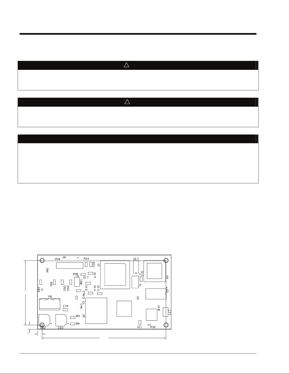
Each MicroTech II L
ONWORKS Communication Module is a printed circuit board that plugs onto the MicroTech II unit
controller. Figure 1 is an outline drawing with dimensions of a printed circuit board.
Figure 1. MicroTech II L
3.750
ONWORKS COMMUNICATION MODULE
®
variables used on the network to the variables used
®
Space Comfort
0.250
6 IM702-4
0.250
6.750
Page 7
Application
12
The MicroTech II LONWORKS Communication Module connects the MicroTech II rooftop or self-contained unit controller
to the Building Automation System (BAS) on a L
variables between the network and the unit controller. The MicroTech II LonWorks Communication Module translates the
ONWORKS variables of the profile into the native information of the unit controller. Figure 2 shows the MicroTech II
L
ONWORKS Communication Module and unit controller integrated into a BAS. Refer to the appropriate Unit Operation
L
manual for keypad details (see Reference Documents section).
Figure 2. Building Automation System
ONWORKS network. It is the interface adapter for the exchange of LonTalk
LonWorks
FTT-10A
Network
MicroTech II
Main Control
Board
MicroTech II
LonWorks
Communications
Module
MicroTech II
Keypad
LonWorks W ork Station
LonWorks
Interface
Adapter
Component Data
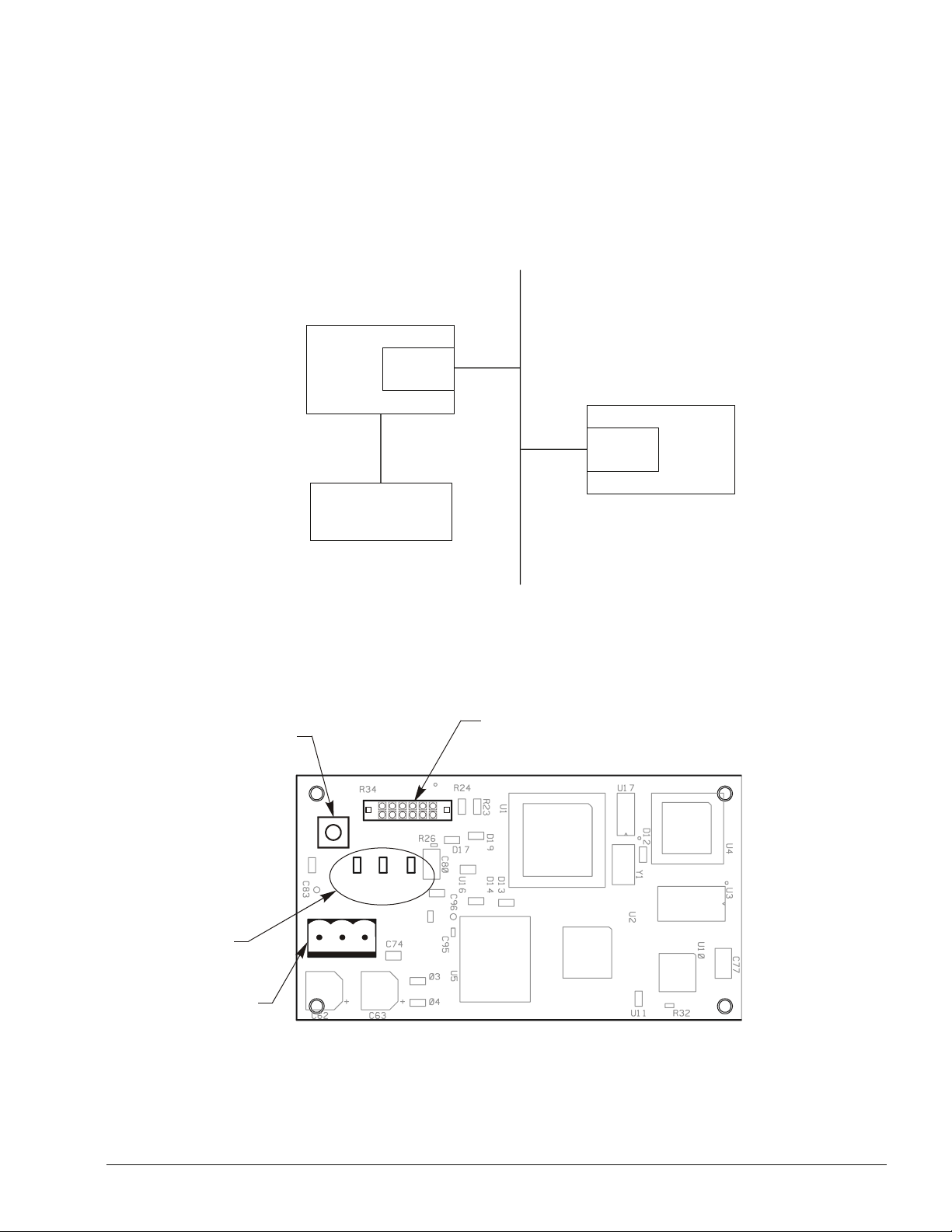
Figure 3 shows the location of the major components of the MicroTech II LONWORKS Communication Module.
Figure 3. MicroTech II L
ONWORKS Communication Module Major Components
-Pin Header
Service Pin
SW1
J6
DS1
DS2
DS3
P8
Light Emitting Diodes
3
12
P8 Connector
Service Pin
The service pin, switch SW1, generates a service pin message, which contains the Neuron ID and the program code
identification of the node. A service pin message is a network message that is generated by a node and broadcast on the
network. It can be used to commission the L
IM702-4 7
ONWORKS network.
Page 8

Light Emitting Diodes (LEDs)
The communications module has three LEDs to indicate communication activity and status of the communication module.
LED Function
DS1 Lights when the service pin is pressed
Lights when there is a problem with the module
DS2 On Steady during normal operation
Blink during a Wink command
DS3 Flicker during Communications Activity
Blink during a Wink command
LONWORKS Network Connector (P8)
The P8 connector connects the MicroTech II LONWORKS Communication Module to the LONWORKS FTT-10A bus.
Pin Designation Function
1 None No Connection
2 - (minus sign) FTT-10A
3 + (plus sign) FTT-10B
12-Pin Header
The 12-pin header, J6, connects the unit controller main control board to the MicroTech II LONWORKS Communication
Module through the bottom of the module.
LonMark Profile Software
The MicroTech II LONWORKS Communication Module software translates the Standard Network Variable Types (SNVTs)
and Standard Network Configuration Parameters (SCPTs) in accordance with the LonMark profiles used on the L
network into the variables and parameters used in the MicroTech II rooftop unit controller.
ONWORKS
Neuron
The basis of the communications module is an Echelon Neuron chip. Each Neuron chip stores a globally (i.e., worldwide)
unique, 48-bit serial number called the Neuron ID. The Neuron ID can be used to address the device on the L
ONWORKS
network.
Transceiver
The Echelon® Corporation Free Topology Transceiver (FTT-10A) is used to communicate on the LONWORKS network. The
network topology may consist of a: star, daisy-chain, or other topology. Data transmission rate on the network is 78 kbps
(baud).
Specifications
Characteristic Description
Network Topology Flexible Free Topology
Neuron Chip Processor 3150
Free Topology Transceiver (FTT-10A) 50051
Cable Types TIA Category 5 (recommended)
Maximum Bus Length 1476 ft (450) meters per segment
Maximum Node Separation 820 ft (250 meters)
Data Transmission Two-wire, half duplex
Data Transmission Rate 78 kbps (baud)
8 IM702-4
Page 9

Installation and Network Connection
General
The MicroTech II LONWORKS Communication Module can be factory or field installed and can be purchased by itself or as
a kit. The kit includes a wire harness and this Installation Manual. See Replacement Parts for detailed descriptions and part
numbers.
This document provides the information required to field install the MicroTech II L
the MicroTech II rooftop or self-contained unit controller and connect it to the L
ONWORKS Communication Module on
ONWORKS network. The module mounts on
connector pins and is held in place with four plastic locking standoffs. A cable harness connects the MicroTech II
ONWORKS Communication Module to field wiring terminals and the LONWORKS network at a terminal block in the unit
L
cabinet assembly.
Required Equipment
Field installation and network connection requires the following:
• A MicroTech II L
ONWORKS Communication Module (included in kit)
• Wire harness (included in kit)
• L
ONWORKS FTT-10A acceptable network wiring (refer to Qualified Cables section for details)
• Small straight-blade screwdriver
Mounting a new MicroTech II LONWORKS Communication Module
1. Remove power from the rooftop or self-contained unit controller.
2. Remove the plug-in connector terminal block in P8 (see
3. Locate the blank connector and four standoffs for the MicroTech II LONWORKS Communication Module on the unit
controller’s main control board (see
Figure 4.)
4. Orient the printed circuit board so that the side with the components faces out and connector pins can penetrate the
connector on the board.
5. Push the board onto the connector pins and standoffs until you hear the faint click of the locking standoffs securing the
board in place.
Connecting the MicroTech II LONWORKS Communication Module to the Network: Applied Rooftop Units
1. Connect the MicroTech II L
.)
7
ONWORKS Communication Module to the network with provided wire harness (see Figure
2. Connect the cable harness white/blue wire (No. 522) to the A terminal of the P8 connector. Connect the blue wire (No.
523) to the B terminal of the P8 connector. No wire is connected to the remaining terminal of P8.
3. Route the cable harness down to the shelf below the unit controller and to the left along the shelf to the edge. Route the
cable through a hole down the raceway to Terminal Block TB2.
4. Connect the cable harness white/blue wire (No. 522) to terminal 128 of TB2. Connect the blue wire (No. 523) to
terminal 129 of TB2.
5. Connect the network cable to TB 2 terminals 128 and 129 (see
Connecting the MicroTech II L
1. Connect the MicroTech II L
ONWORKS Communication Module to the Network: Self-Contained Units
ONWORKS Communication Module to the network with wire harness (see Figure 8.)
2. Connect the wire harness white/blue wire (No. 522) to the + terminal of the P8 connector. Connect the blue wire (No.
523) to the - terminal of the P8 connector. No wire is connected to the remaining terminal of P8.
3. Route the wire harness over to the right side of the unit controller and up to Terminal Block TB2
4. Connect the wire harness white/blue wire (No. 522) to terminal 128 of TB2. Connect the blue wire (No. 523) to
terminal 129 of TB2.
5. Connect the network cable to TB 2 terminals 128 and 129 (see
Figure 3.)
Figure 5).
Figure 5).
Replacing a MicroTech II LONWORKS Communication Module
To replace an existing MicroTech II LONWORKS Communication Module on a rooftop or self-contained unit controller:
1. Remove power from the unit controller.
2. Remove the connector in P8 (see
IM702-4 9
Figure 3.)
Page 10

3. Locate the four standoffs for the MicroTech II LONWORKS Communication Module on the unit controller’s main control
board.
4. Use a small screwdriver to depress the barb on one standoff and gently pull the corner of the board over the barb. Be
careful to not bend the board or misalign the connector pins.
5. Proceed to the other three corners and pull the board over the standoffs.
6. Gently lift the MicroTech II L
7. Locate the blank connector and four standoffs for the MicroTech II L
controller (see
Figure 4.)
ONWORKS Communication Module from the unit controller.
ONWORKS Communication Module on the unit
8. Orient the board so that the side with the components faces out and connector pins can penetrate the connector on the
board.
9. Push the board onto the connector pins and standoffs until you hear the faint click of the locking standoffs securing the
module in place.
Connecting the MicroTech II LONWORKS Communication Module to the Network
1. Replace the network plug in P8 (see
2. Reconnect the network cable to TB 2 terminals 128 and 129 if necessary (see
Figure 3.)
Figure 5).
Figure 4. MicroTech II Applied Rooftop Unit Controller Main Control Board
Main Control Board
Terminal Block Connector
Connector
Location of Standoff
(4 places)
10 IM702-4
Page 11

Figure 5. LONWORKS Network Connection Schematic Diagram
12
Unit
Te rm in a l
Block
Tb2
Main
Control
Board
(MCB)
LonWorks Network
Figure 6. Mount L
128
129
ONWORKS Communication Module
522
523
-Pin Header
LonWorks
Communications
+
A
-
B
Module
Communications Module
Locking Standoff
IM702-4 11
Page 12

Figure 7. Cable Harness Routing - Applied Rooftop Unit
Controller
Network Cable
Cable Raceway
LonWorks
Communications
Comunications
Module
Cable Shelf
Terminal Block TB2
12 IM702-4
Page 13

Figure 8. Cable Harness Routing - Self-Contained Unit
Controller
LonWorks
Communications
Comunications
Module
Terminal Block TB2
Network Cable Harness
IM702-4 13
Page 14

Integration
Integrating the MicroTech II LONWORKS Communication Module into a BAS involves three steps:
• Physically connecting the MicroTech II unit controller (node) to the network
• Addressing and establishing communications with the unit controller
• Configuring the unit controller to the building
Network Connection
After inserting the MicroTech II LONWORKS Communication Module to the MicroTech II unit controller, connect the
MicroTech II unit controller into the L
document for details.)
Network Topology
Each MicroTech II LONWORKS Communication Module is equipped with an FTT-10A transceiver for network
communications. This transceiver allows for (1) free topology network wiring schemes using twisted pair (unshielded)
cable and (2) polarity insensitive connections at each node. This feature simplifies installation and reduces potential network
commissioning errors. Additional nodes may be added with little regard to existing cable routing.
Free Topology Networks
A LONWORKS "free topology network" means that devices (nodes) can be connected to the network in a variety of
geometric configurations. For example, devices can be daisy-chained from one device to the next, connected with stub
cables branching off from a main cable, connected using a tree or star topology, or any of these configurations can be mixed
on the same network (see Figure 9.) Free topology segments require termination for proper transmission performance. Only
one termination is required. It may be placed anywhere along the segment. Refer to Echelon L
Transceiver User's Guide.
ONWORKS network (see Installation and Network Connection section of this
ONWORKS FTT-10A
Free topology networks may take on the following topologies:
• Bus
• Ring
• Star
• Mixed - Any combination of Bus, Ring, and Star
Note: Limitations to wire lengths apply and must be observed.
Figure 9. Singly Terminated Free Topology Networks
Ring Topology
Singly Terminated Bus Topology
Termination
Te rm i na t io n
Mixed Topology
Star Topology
Stub
}
Termination
Termination
14 IM702-4
Page 15

A network segment is any part of the free topology network in which each conductor is electrically continuous. Each of the
four diagrams in Figure 9 is an illustration of a network segment. Some applications may require two or more segments (see
Free Topology Restrictions section). If necessary, segments can be joined with FTT-10A-to-FTT-10A physical layer
repeaters. See Figure 10. Refer to Echelon L
ONWORKS FTT-10A Transceiver User’s Guide.
Figure 10. Combining Network Segments With a Repeater
Termination Termination
FTT-10A
FTT-10A
Free Topology Restrictions
Although free topology wiring is very flexible, there are restrictions. Refer to the Echelon LONWORKS FTT-10A User’s
Guide for details.
1. The maximum number of nodes per segment is 64.
2. The maximum total bus length depends on the wire size (see Physical Networks section for details.)
3. One termination is required in each segment. It may be located anywhere along the segment.
Wire Size Maximum Node-to-Node Length Maximum Cable Length
24 AWG 820 ft (250 m) 1476 ft (450 m)
22 AWG 1312 ft (400 m) 1640 ft (500 m)
16 AWG 1640 ft (500 m) 1640 ft (500 m)
The longest cable path between any possible pair of nodes on a segment must not exceed the maximum node-to-node
distance. If two or more paths exist between a pair of nodes (e.g., a loop topology), the longest path should be considered.
Note that in a bus topology, the longest node-to-node distance is equal to the total cable length.
The total length of all cable in a segment must not exceed the maximum total cable length.
Doubly Terminated Networks
You can extend the maximum total cable length without using a repeater by using doubly terminated network topology. See
Figure 11. The trade-offs are (1) this network topology must be rigorously followed during the installation and subsequent
retrofits and (2) two terminations must be installed at the ends of the bus for proper transmission performance. Refer to
Echelon L
ONWORKS FTT-10A Transceiver User’s Guide. Limitations to wire lengths apply and must be observed.
Figure 11. Doubly Terminated Network Topology
Termination Termination
Doubly Terminated Topology Restrictions
The restrictions on doubly-terminated bus topology are as follows:
1. The maximum number of nodes per segment is 64.
2. The maximum total bus length depends on the wire size (see Qualified Cables section for details).
3. The maximum stub length is 9.8-ft (3 m). The length of the cable harness stub is 7.2-ft (2.19 m).
4. Two terminations are required in each segment. One must be located at each end of the bus.
Wire Size Maximum Cable Length
24 AWG 2952 ft (900 m)
22 AWG 4590 ft (1400 m)
16 AWG 8855 ft (2700 m)
IM702-4 15
Page 16

Note: A stub is a piece of cable that is wired between the node and the bus (see Figure 9.) Note that if the bus is wired
directly to the node, there is no stub, and thus the stub length is zero. If you are wiring to a field terminal strip on a
unit, you must account for any factory wiring between the terminal strip and the controller. This wiring is
considered part of the stub.
Physical Network
Qualified Cables
Echelon has qualified three twisted-pair network communications cables that are available from various sources. Refer to
Echelon L
use of plenum rated cable. The following cables meet this specification.
• TIA568A Category 5 cable (24AWG/0.51mm)
• NEMA Level IV cable (22AWG/0.65mm)
• Generic 16AWG (1.3mm) (similar to Belden 85102)
Do not install the cable in the same conduit with power wiring. The temperature of the cable must not exceed 131°F (55°C).
Note: Ideally, you should connect two controllers with one continuous piece of cable in order to reduce the risk of com-
Network Cable Termination
L
ONWORKS network segments require termination for proper data transmission performance. The type and number of
terminations depend on network topology. Refer to Echelon L
ONWORKS FTT-10A Free Topology Transceiver Users Guide. Some local codes or applications may require the
munications errors. If you must splice the cable, use crimp-type butt connectors (good) or solder (best). Do not
use wire nuts.
ONWORKS FTT-10A Transceiver User’s Guide.
16 IM702-4
Page 17

Addressing and Establishing Communications
The following steps are required to establish communication between the MicroTech II LONWORKS Communication
Module and the L
ONWORKS network:
• Press the service pin on the MicroTech II L
• Address the unit controller (device) using a L
ONWORKS Communication Module
ONWORKS network configuration software tool (software must be
procurred separately)
General
Every Neuron Chip has a unique 48-bit Neuron ID or physical address. This address is generally used only at initial
installation or for diagnostic purposes. For normal network operation, a device address is used.
Device addresses are defined at the time of network configuration. All device addresses have three parts. The first part is the
Domain ID, designating the domain. Devices must be in the same domain in order to communicate with each other. The
second part is the Subnet ID that specifies a collection of up to 127 devices that are on a single channel or a set of channels
connected by repeaters. There may be up to 255 subnets in a domain. The third part is the Node ID that identifies an
individual device within the subnet.
A group is a logical collection of devices within a domain. Groups are assembled with regard for their physical location in
the domain. There may be up to 256 groups in a domain. A group address is the address that identifies all devices of the
group. There may be any number of devices in a group when unacknowledged messaging is used. Groups are limited to 64
devices if acknowledged messaging is used.
A broadcast address identifies all devices within a subnet or domain.
L
ONWORKS Network Addressing
Pressing the service pin, switch SW1, generates a service pin message, which contains the Neuron ID and the program code
identification of the node. A service pin message is a network message that is generated by a node and broadcast on the
network. It can be used to commission the L
A L
ONWORKS network configuration tool (such as LonMaker®) maps device Neuron IDs to the domain/subnet/node logical
ONWORKS network.
addressing scheme when it creates the network image, the logical network addresses, and connection information for all
devices (nodes) on the network.
External Interface File (XIF)
LonMark guidelines specify exact documentation rules so that proprietary configuration tools are not required to
commission and configure L
documenting so that any network management tool can obtain all the information needed over the network to connect it into
the system and to configure and manage it. An external interface file (a specially formatted PC text file with an extension
.XIF) is also available so that any network tool can design and configure it prior to installation. The XIF file is available on
www.mcquay.com.
ONWORKS devices. The MicroTech II LONWORKS Communication Module is self-
IM702-4 17
Page 18

Configuring the Unit Controller
All Rooftop and Self-contained unit controllers are loaded with software and configured at the factory for stand-alone
operation. The unit is ready to operate with default set point parameters that can be changed with the unit’s keypad/display
or via a network signal. Refer to the appropriate operation manual for the default values and keypad/display operating
instructions. Refer to the appropriate MicroTech II Protocol Information documents for descriptions of the available network variables (see Reference Documents section).
There are 12 communication parameters involved in setting up the unit controller for proper communication with the
various communication module options (BACnet IP, BACnet MS/TP or LONWORKS). These parameters are set
differently by the factory depending on which communication module is ordered and shipped with the unit. Table 1 below
lists the four possible sets of default parameter settings. Not all the parameters apply to all the communication module
options. The entries in the table that are shown in bold font apply to a particular communication module option.
Factory-Installed LONWORKS Communication Modules
If the rooftop or self-contained unit controller is equipped with a factory-installed LONWORKS Communication Module
(DAC or SCC), the controller is pre-configured with the values shown in Table 1. These parameters do not require field
modification.
Field-Installed LONWORKS Communication Modules
A LONWORKS Communication Module can be added to a rooftop or self-contained unit controller in the field for these
reasons:
1. The unit did not originally ship with a communication module.
2. The unit originally shipped with a BACnet
Communication Module. Refer to Table 1 to determine whether or not changes are required to communication setup
parameters.
®
Communication Module but requires replacement with a LONWORKS
3. The LONWORKS Communication Module that shipped with the unit requires replacement.
Note: McQuay MicroTech II ServiceTools™ software is required to modify these parameters. Call the McQuay
Controls Customer Support group at 866-4MCQUAY for more information.
Table 1. Factory Communication Setup Parameter Settings
Parameter Name BACnet IP BACnet MSTP LON (DAC or SCC) No Communication
Module
lP Address 172.16.83.46 172.16.83.46 172.16.83.46 172.16.83.46
IP Subnet Mask 255.255.0.0 255.255.0.0 255.255.0.0 255.255.0.0
UDP Port Number 47808 47808 47808 47808
IP Router Address 172.16.128.0 172.161.28.0 172.16.128.0 172.16.128.0
IP Network Address 1001 1001 1001 1001
MSTP Network Address 2001 2001 2001 2001
MSTP MAC Address
1
129 2 129 129
MSTP Baud Rate 19200 19200 19200 19200
Communication Option None MSTP MSTP MSTP
Device Instance Number2XXXXXX XXXXXX XXXXXX XXXXXX
Max APDU Length
Device Object Name
3
4
1024 501 501 501
MTll RTUC
XXXXXXXXX
or
MTII SCUC
XXXXXXXXX
MTll RTUC
XXXXXXXXX
or
MTII SCUC
XXXXXXXXX
MTll RTUC
XXXXXXXXX
or
MTII SCUC
XXXXXXXXX
MTll RTUC
XXXXXXXXX
or
MTII SCUC
XXXXXXXXX
Important Notes
1. The MSTP MAC Address is not adjustable from MicroTech II ServiceTools software. It is set via the dipswitch block
on the MSTP communication module.
2. The Device Instance Number is factory set equal to the last six significant digits of the 18 digit number on the barcode
label on the unit's main control board (MCB). For example if the last six digits are 043.066, then the Device Instance
Number is set to 43066. Whether or not this parameter is use by the system integrator, it must be set to a unique value
from all other controllers in the network.
18 IM702-4
Page 19

3. The Max APDU Length parameter should not be set higher than 1024 for BACnet IP or 501 for BACnet MSTP.
4. The Xs in Device Object Name are factory set equal to the last nine digits of the 18 digit number on the bar-code label
on the units main control board (MCB). For example if the last nine digits are 000.043.066, then the Device Object
Name is set to MTII RTUC 000043066 for an applied rooftop unit or MTII SCUC 000043066 for a vertical selfcontained unit. Whether or not this parameter is use by the system integrator, it must be set to a unique value from all
other controllers in the network.
IM702-4 19
Page 20

Service Information
Troubleshooting
If you can control the unit from the unit’s keypad, but you are not able to communicate with unit via the network:
• Check the network wiring.
• Check the cable harness to the network terminals.
• Check addressing.
• Press the Service Pin on the MicroTech II L
ONWORKS Communication Module to send the service message to the
network.
• The service pin message contains the Neuron ID and the program code identification of the node.
• Check the network communication set up parameters in the controller for proper settings (see Configuring the Unit
Controller section).
If the MicroTech II LONWORKS Communication Module still does not respond, contact McQuay Controls Customer
Support at 866-4MCQUAY (866-462-7829).
Replacement Parts
Contact the McQuay Parts group at 763-553-5451 for replacement parts related to the LONWORKS Communication
Module. McQuay does not supply the network connection plug. The three-contact network connection plug has custom
graphics, but can be replaced with a standard network connector. The table below provides two manufacturers with the
generic version of the network connection plug.
Description Part Number Contact
LONWORKS Communication Module (SCC) installation kit (kit includes
communication module, wire harness and IM)
LONWORKS Communication Module (DAC) installation kit (kit includes
communication module, wire harness and IM)
LONWORKS Communication Module (SCC) 060006203 McQuay Parts
LONWORKS Communication Module (DAC) 060006204 McQuay Parts
Wire harness 090011184 McQuay Parts
Network connection plug 17 57 02 2 Phoenix Contact
Network connection plug 37.003 Altech Corp
090016703
McQuay Parts
090016704 McQuay Parts
20 IM702-4
Page 21

This document contains the most current product information as of this printing. For the most current product
information, please go to www.mcquay.com.
© 2007 McQuay International • www.mcquay.com • 800-432-1342
IM702-4 21
 Loading...