

Page 1

Training Manual
Software
Water quality
Air supply Gas
Flue venting
Drain
Basics, Maintenance and Accessories
SelfCookingCenter® whitefciency® (SCC_WE)
CombiMaster Plus (CM_P)
Voltage
Installation
Accessories
Original components
Type of gas
V02 en, Basic_Maintenance_Accessories
Page 2

General hints:
Isolate the appliance from mains supply before opening the appliance
When working with chemicals, i.e. aggressive cleaning materials
always wear protective clothing, goggles and gloves!
After maintenance / repair the appliance must be checked for electrical
safety in accordance with your national, state and local requirements!
Whenever working on any gas component like:
Gas valve, gas blower and / or changing connected type of gas a detailed
ue gas analysis MUST be done using adequate CO and CO2
measuring equipment! This shall ONLY be done by trained technicians!
Always check appliance for possible gas leakages!
© 2011 Rational Technical Services. All rights reserved.
Please note that any technical information concerning Rational products
must NOT be forwarded to any third party.
V02 en, Basic_Maintenance_Accessories - 2 -
Page 3

List of content
Basic topics
Company history 4
History of the Combi Steamer 5
Structure of serial number 6
Unit history: Control panel Layout 7
Unit sizes 8
Basic principle 9
General information about water 10
Installation - Duties and responsibilities 12
Relationship: Installation - Components - Environment 13
Check list
Preinstallation checklist 14
Installation sheet - Electric / Gas units - Electrical connection 18
Installation sheet - Electric / Gas units - Water connection 19
Installation sheet - Electric / Gas units - Drain connection 20
Installation sheet - Gas units - Gas connection 21
Commissioning - Preventive maintenance
Installation/Commissioning Checklist 22
Preventive maintenance 27
Descaling - Cleaning
Instruction
for manual descaling 30
Additional information for manual descaling 33
User instruction electrical descaler pump 34
Daily care - Unit and Door Gasket 36
Instruction for manual cleaning 37
Accessories
Ultravent (UV) 38
CombiDuo, Thermo cabinet 41
Condensation breaker steam 42
Draft Diverter Gas units 42
Sicotronic 43
Ethernet Connection 43
Reporting forms
Product surveillance guideline 44
Registration form product surveillance 45
Registration form „dead on arrival“ 46
- 3 - V02 en, Basic_Maintenance_Accessories
Page 4

Company history
Milestone of an extraordinary company history
1973 Foundation of RATIONAL GmbH as a company for producing and selling of hot air ovens in
Germany
1976 Invention of the RATIONAL Combi-Steamer
1993 Opening of plant number 2
1993 Invention of the RATIONAL Clima Combi®
1997 Invention of the RATIONAL ClimaPlus Combi®
2000 Going public RATIONAL AG
2000 CleanJet® – World wide the rst full automatic self clean system
2004 Invention of the rst SelfCooking Center® of the world
2005 Invention of the rst VarioCooking Center® of the world by our daughter company
FRIMA. Cooking, roasting, frying, simply better, in one appliance, with double speed.
2008 Opening of the third and biggest plant in Landsberg
2008 CleanJet
+Care®
– cleaning intelligence for a maximum reliability
2011 Invention of SelfCooking Center whitefciency with Efcient Level Control
The following subsidiaries were founded:
UK, France, Japan, USA, Italy, Scandinavia, Switzerland, Canada, Spain,
Germany, Russia, Austria, Poland, China, Greece, Middle East and Brasil
V02 en, Basic_Maintenance_Accessories - 4 -
Page 5
History of the Combi Steamer
11C9103 1234 03-1991 05-1997
Low Temp Cook (LT)
Product line: Designation: Serial number Produced Produced
as of up to
Classic Line CD Steam, Hot air, Combi (S, HA, CS) 1018909 1234 1976 05-1997
CM (S, HA, CS) Vario-Steam (VS) 11M8610 1234 1986 11-1989
CM (S, HA, CS, VS), Reheating (R) 11M8904 1234 04-1989 04-1991
CC (S, HA, CS, VS, R)
CM S, HA, CS, VS, R 11M9104 1234 04-1991 05-1997
CM Gas (101) 14G9104 1234 04-1991 10-1997
CM Gas (201) 21G9301 1234 01-1993 10-1997
CM Gas (62) 62G9403 1234 03-1994 10-1997
C-Line
C-Line 61, 101 CCD – CCM - CCC CCM, CCC: humidity control C11D93101234 10-1993 05-1995
C-Line 201, 202 CCD – CCM - CCC C11M93101234 10-1993 05-1997
C-Line 61, 101 CCD – CCM - CCC C11C95051234 05-1995 05-1997
C-Line 102 CCD – CCM - CCC C12C95101234 10-1995 05-1997 CPC Line :
- 5 - V02 en, Basic_Maintenance_Accessories
ClimaPlus Combi® CD – CM - CPC CPC: ClimaPlus control E11CA97051234 05-1997 02-1999
CM Gas, CPC Gas G11CA97101234 10-1997 02-1999
CPC New humidity control E11CB99021234567 02-1999 03-2004
CPC IQT Sensor E11CB99101234567 10-1999 03-2003
CPC CleanJet®, CDS® E11CC00031234567 03-2000 03-2004
CM Gas, CPC Gas Electronic motor control, G11CD01011234567 01-2001 03-2004
230V burner control
CM, CPC Electric Electronic motor control E11CD01031234567 03-2001 03-2004
CD – CM - CPC Elimination of motor protector E11CD01121234567 12-2001 03-2004
SCC Line
SelfCooking Center® CM Electric / Gas E11ME04042345678 04-2004 01-2006
CM Electric / Gas New CPU pcb E11MF06022345678 02-2006 09-2008
CM Electric / Gas Extension of warranty E11MG08102355678 10-2008 09-2011
SCC Electric / Gas E11SE04042345678 04-2004 09-2008
SCC Electric / Gas CareControl / Extension of warranty E11SG08102445678 10-2008 09-2011
CM_P Electric / Gas Programmable and humidity control E11MH1109 09-2011
SCC_WE Electric / Gas Efcient Level Control E21SH1109 09-2011
Page 6
Structure of serial number
Classic Line - 05 / 1997 Serial number
Unit size Type
06 - 6x1/1GN Size Type Year Month Serial-#
11 - 10x1/1GN CD 006 94 07 1234
21 - 20x1/1GN CM 06 M 95 08 1235
20 - 20x2/2GN CC 20 C 96 10 1236
14G - CM 101 Gas (1x1/1GN) 21G - CM 201G (21x1/1GN) 62G - CM 62G (6x2/1GN)
C - Line - 10 /1993 - 05 /1997 Serial number
Unit size Type
61 - 6x1/1GN Family Size Type Year Month Serial-#
11 - 10x1/1GN
12 - 10x2/1GN CCD C 61 D 95 08 1234
21 - 20x1/1GN CCM C 11 M 95 11 1235
22 - 20x2/2GN CCC C 21 C 96 05 1236
CPC- Line - 06/1997 - 04/2004 Serial number
Unit size Type E - Elec.
G - Gas
61 - 6x1/1GN Family Size Type Version Year Month Serial-#
11 - 10x1/1GN A
12 - 10x2/1GN CD E 61 D B 98 12 1234
21 - 20x1/1GN CM E 12 M C 99 01 1234567
22 - 20x2/2GN CPC G 22 C D 96 05 1458967
SCC- Line - 04/2004 - Serial number
Unit size Type E - Elec.
G - Gas
61 - 6x1/1GN Family Size Type Version Year Month Serial-#
11 - 10x1/1GN
12 - 10x2/1GN E 21 S E 04 05 2345678
21 - 20x1/1GN CM E 06 M F ( CM) 06 02 2434567
22 - 20x2/2GN SCC G 11 S G 08 10 2534567
CM_P E 11 M H 11 09 2567892
SCC_WE G 21 S H 11 09 2569812
V02 en, Basic_Maintenance_Accessories - 6 -
Page 7
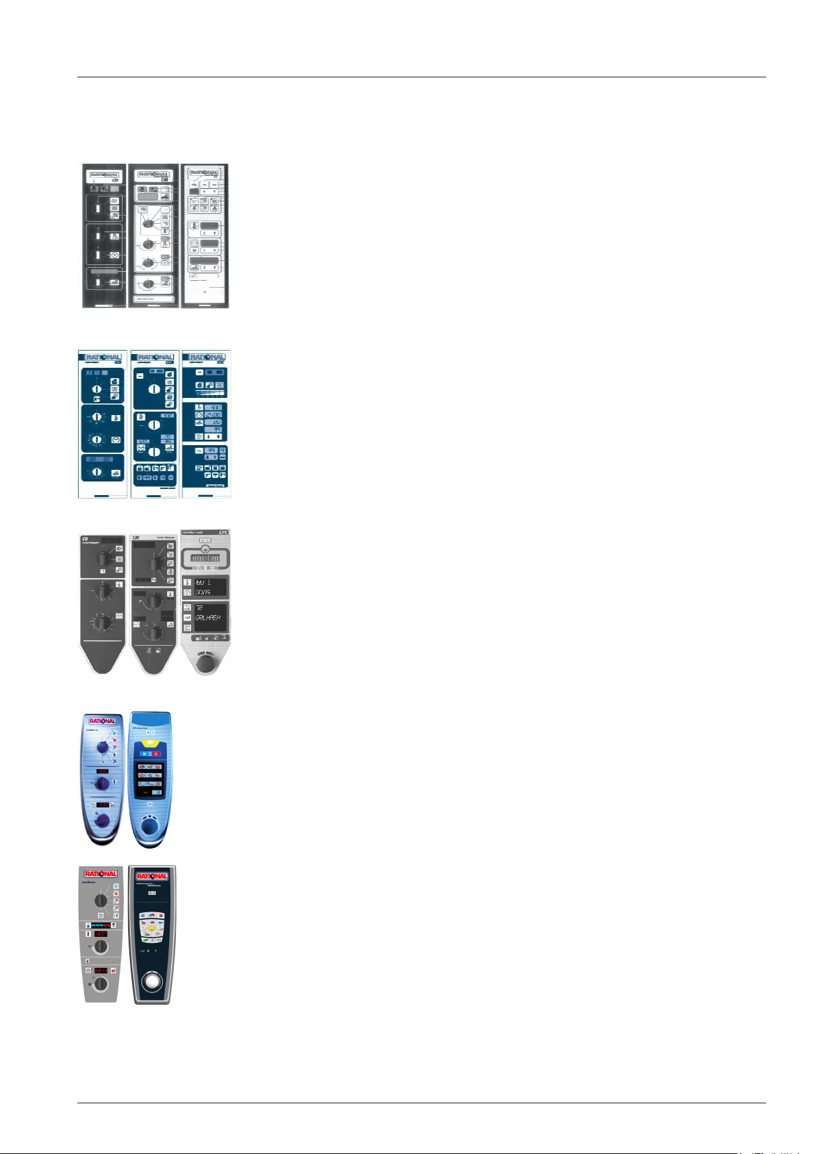
Unit history: Control panel Layout
Classic Line, CD, CM, CC
C-Line, CCD, CCM, CCC
CM SCC
CM_P SCC_WE
CPC Line, CD, CM, CPC
SCC Line, CM, SCC
Combi Master Plus , SCC_WE „whitefciency“
- 7 - V02 en, Basic_Maintenance_Accessories
Page 8
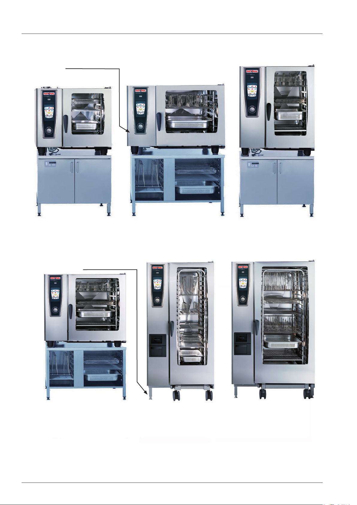
Unit sizes
Serial number
SelfCooking Center
6 x 1/1 GN
Thermo Cabinet
Serial number
®
SelfCooking Center
6 x 2/1 GN
Base stand
®
SelfCooking Center
®
10 x 1/1 GN
SelfCooking Center
10 x 2/1 GN
V02 en, Basic_Maintenance_Accessories - 8 -
®
SelfCooking Center
20 x 1/1 GN
®
SelfCooking Center
®
20 x 2/1 GN
Page 9
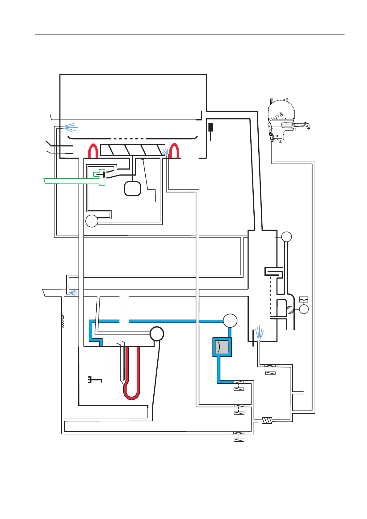
Basic principle
B1
Cabinet
B3.1 - 3.6
Core sensor (CT)
Safety thermostat STB
F4
Cabinet sensor
Diff. pressure sensor
Venting pipe
Y5
P1
Clima valve
Fan motor
M1
Humidity
Air bafe
B4
thermocouple
S3
Hot air heating
element
Door contact switch
Quenching box
M6
Emergency drain
Drain valve
S12
Hand shower roll guide
Check valve
Level electrode
S2
Safety
thermostat
F3
B5
generator
Sensor steam
M4
Self Clean (SC) pump
Steam heating element
Solenoid valve
Steam generator
Care
moistening
M12
Solenoid valve
llling
Quenching
B2
Solenoid valve
Care
Y4
Y3
Y1
sensor
Y2
Solenoid valve
quenching
S11
M7
Drain
Water supply
- 9 - V02 en, Basic_Maintenance_Accessories
Page 10
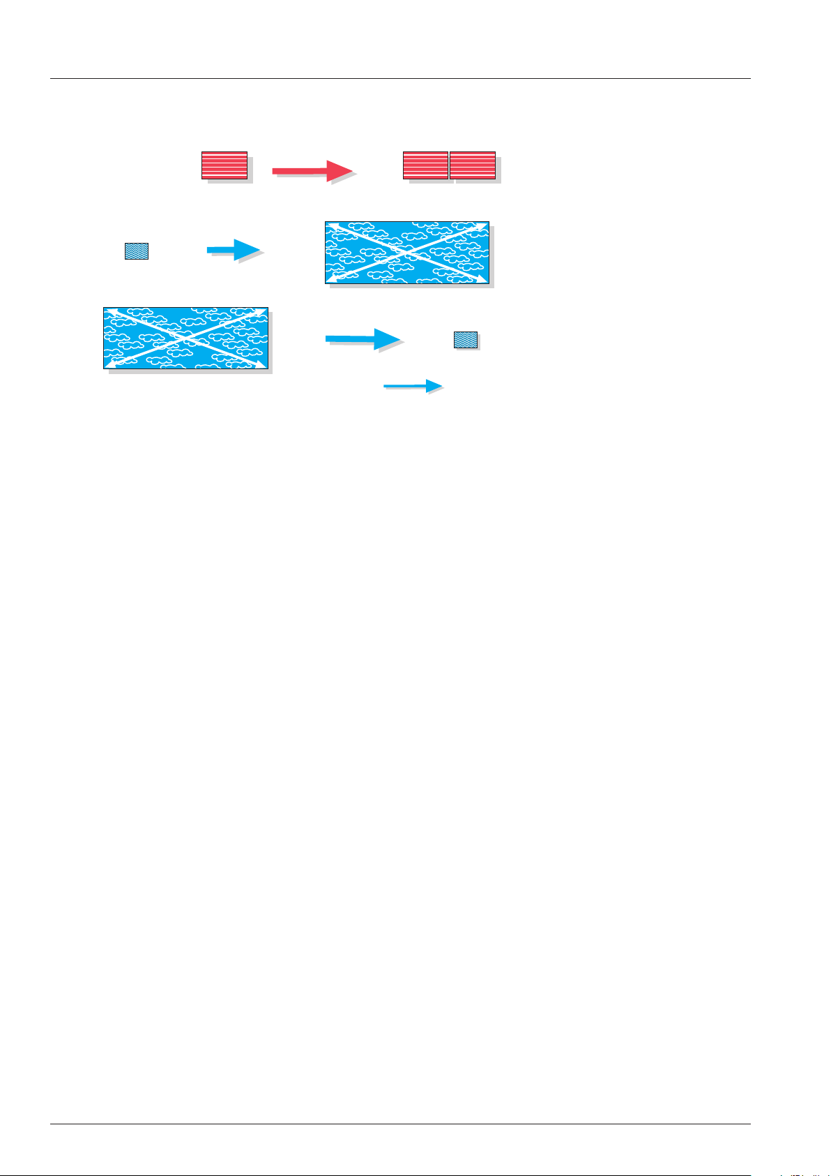
1l
1700l Steam
approx.1700l Steam
1l
Water
Expansion through
heat energy
Volume reduction
through quenching
E+
E-
1dm
3
30°C
E+
300° C
2dm
3
Steam
Hot air
volume
Water
cold water
General information about water
Water- / Steam ratio
The conductivity of the connected water should be above 50µS/cm (micro Siemens).
The measured total hardness (TH) is normally higher than the measured amount of Carbonate hardness - calcium or magnesium carbonat (CaCO
Should the total hardness be less than the Carbonate hardness, most likely a water treatment system is
connected.
, MgCO3).
3
Common terms:
Total hardness TH is the measure of carbonate (CH) and non-carbonate
hardness (NCH) in the water
Carbonate hardness CH is the measure of bicarbonate (HCO3-) and carbonate
(CO3--) ions in the water;
Temporary water hardness; Forms sediments when
boiled;
Non-carbonate hardness NCH Calcium and Magnesum ions in the water;
permanent water hardness which can not be removed by
boiling
Water hardness e 1°dH = 1,25°e = 1,78°f = 17,8 ppm/l = 0,178 mmol/l
Chlorine Cl Gaseous, (used in swimming pools), limit 0,2mg/l
Chloride Cl-- chemical bond of chloride e.g. NaCl, limit 80mg/l
Water Analysis
Which values are required?
- Total hardness TH
- Carbonate hardness CH
- Conductivity in micro Siemens/cm
- Ideal: Water analysis with chloride content value
Possible reasons for corrosion
- excessive usage
- ferritic accessories
- rusting water pipes
- cleaning procedure (Unit is not dry over night)
- water
V02 en, Basic_Maintenance_Accessories - 10 -
Page 11

Water Info
Because of continuous examinations of systems for water treatment we would like to offer you some
information on different systems.
The given statements are only related to Rational units.
1. Recommended systems for water treatment
A) With pure scale problems in the steam generator we recommend hydrogen-(H+)-Ionic ex-
changer. This type of lter will extend the intervals between descales by approx. 5 to 8-times
of the normal descaling intervals. Please note that even with this type of lter it is still neces-
sary to descale the steam generator.
B) With a high chloride content above 80mg/l of water it is possible, that the interior cabinet will
start to corrode. To remedy this problem it is necessary to install a reverse osmosis lter.
C) With chlorine-contents above 0,2 mg/l of water an active carbon lter should be installed, to
avoid corrosive radicals when chlorine is heated up.
D) If the water is soiled with sand, iron particles or suspended matter a particle lter with
5-15 μm is recommended.
2. Limited recommended systems for water treatment
Physical systems for water treatment:
On some sites this type of water treatment showed satisfactory results. On other sites there was
no positive effect visible. Because of these circumstances we can not make a nal assessment of
this system.
3. Non recommended systems for water treatment
A) Sodium-Ionic exchanger:
With this lter system calcium is replaced by sodium. On chloride contents of the water above
50mg/l, sodium reacts with chloride to NaCl (=salt). This increase of salt in the water results in
a delay in boiling of the water. This delay in boiling can cause ”spitting” steam generators.
B) Silicate-dosing systems:
This kind of systems is problematic, as the adding of non conductive silicates, will inuence
the water level measurement.
- 11 - V02 en, Basic_Maintenance_Accessories
Page 12

Installation - Duties and responsibilities
Installation
Responsibilities
Designer / Architect
Make sure that during construction all dimensions needed are correct and sufcient
(Doors, corridors etc)
Make sure that all services (energy, water, drain and exhaust air) are available in
immediate vicinity of the unit
1. Drain
2. Water (Pressure, Water treatment)
3. Power supply and breaker specication
4. Gas connection (type of gas, dimension of supply pipe)
5. Vent hood (possible interconnection with gas supply)
6. Exhaust air for gas units (exhaust hood, ventilation ceiling, chimney, spacing
between top edge of unit to lower edge of fat lters / ceiling)
7. possible need for levelling device for trolley with sloped oor
Document: Pre Installation checklist
Designer Manual
Installer
Make sure the installation complies with the installation manual (part of starter kit) and
the local and / or national legislation / codes
1. Installed horizontally
2. Secured to the ground / stand secured from moving
3. Uneven oor levelled
4. Connected to cold water, possibly treated water, (water line rinsed)
5. Connected to power (equipotential bonding included - where required))
6. Connected to drain (steam temperature resistant pipe, permanent slope,
P-trap)
7. Connected to gas supply (correct type of gas), leakage test up to unit con-
nection point
8. Installation of accessories (Ultravent)
9. Testing of electrical safety
Document: Installation manual
RSP, Dealer
Commissioning and hand over to the customer
1. Conrm installation according to installation manual
2. Commissioning
3. Gas unit: Leakage test inside the unit
4. Gas unit: Flue gas analysis
5. Successful completion of Self Test
6. Function test of all components and cooking modes
7. Demonstration of cleaning mode for customer
8. Demonstration of preventive maintenance for customer (daily cleaning)
9. Download of Service Data
10. Photos of installation site
Document: Installation and commissioning checklist
Installation manual
Operator manual
V02 en, Basic_Maintenance_Accessories - 12 -
Page 13
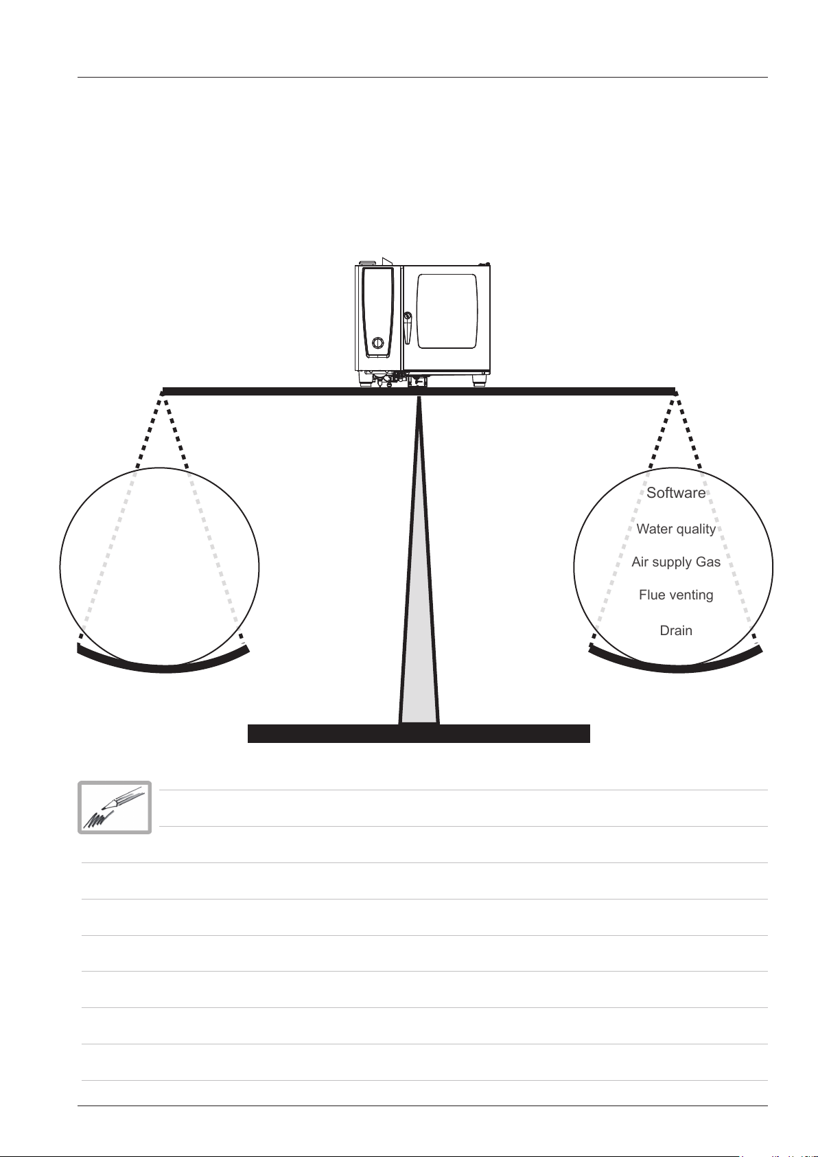
Relationship: Installation - Components - Environment
Software
Water quality
Air supply Gas
Flue venting
Drain
The unit will only function properly, when all components are designed correctly and the installation is
done according to the manufacturers instructions.
Therefore during maintenance and troubleshooting it is mandatory to observe all components together
with the connected services such as electricity, water etc. and the kitchen surrounding and venting.
Every deviation from the installation manual can cause different errors.
Voltage
Installation
Accessories
Original components
Type of gas
- 13 - V02 en, Basic_Maintenance_Accessories
Page 14
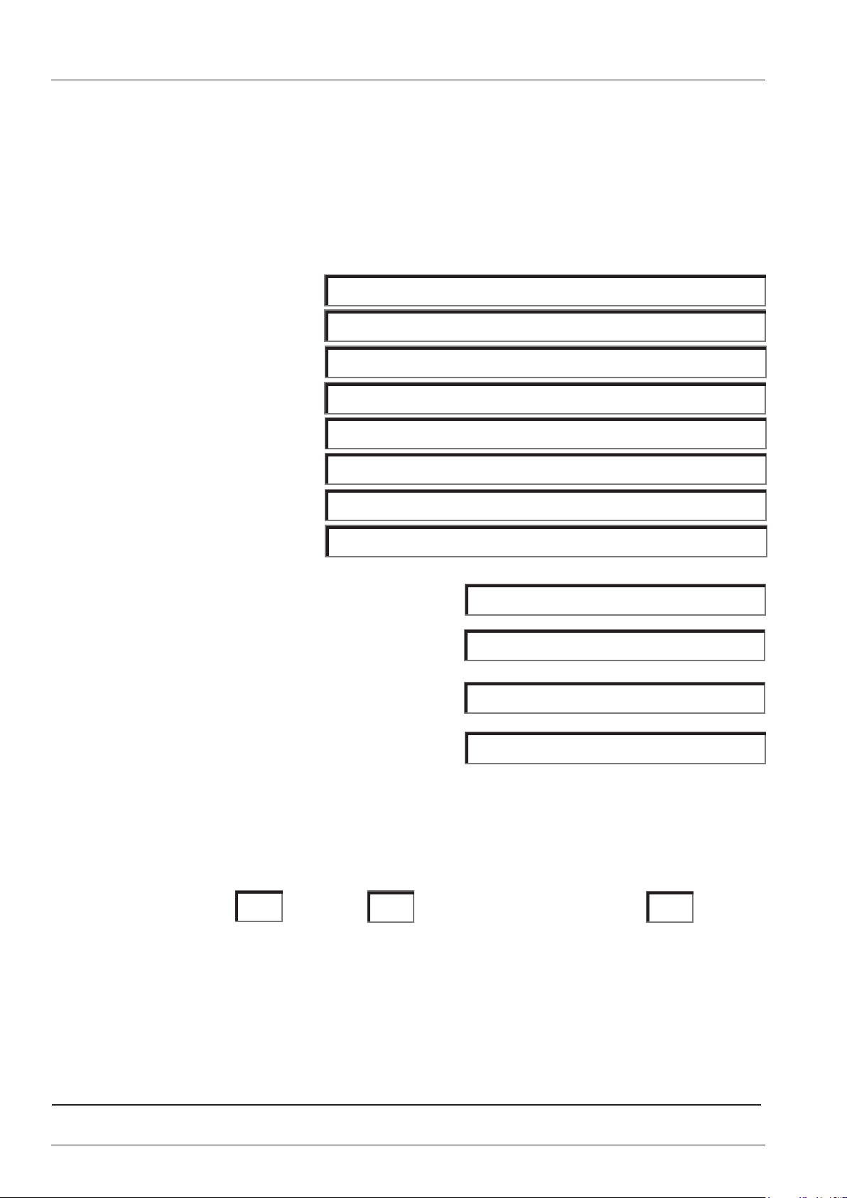
Preinstallation checklist
Preinstallation checklist
Company name:
Name of contact person:
Street:
City:
Country:
Telephone number:
Fax-Number:
E-Mail:
Number of RATIONAL units already installed:
Serial number of installed units:
How many units shall be installed?
What type of unit shall be installed?
Please fill in the form either by making a tick in the corresponding box or writing down the measured
values in the corresponding lines.
All measures, distances, services like electricity, water, drain and gas connection are properly
installed and complying with the list attached.
Yes No additional comments: Yes
Signature: Customer Sales Date
V02 en, Basic_Maintenance_Accessories - 14 -
Page 15
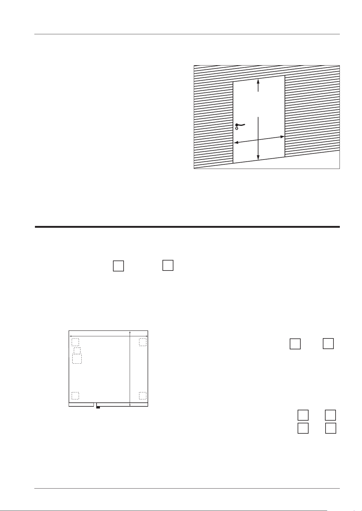
20x1/1 GN /
20x2/1 GN:
1900mm/75"
X (6x1/1 - 20x2/1GN)
Preinstallation checklist
1. Check all doors and corridors for sufficient space
Required door width “X”:
Unit size without pallet with pallet
6x1/1GN 840 mm (33 1/8”) 920mm (36 1/4“)
6x2/1GN 1040 mm (41”) 1120mm (44 1/8“)
10x1/1GN 840 mm (33 1/8”) 920mm (36 1/4“)
10x2/1GN 1040 mm (41”) 1120mm (44 1/8“)
20x1/1GN 920 mm (36 1/4”) 950mm (37 1/2“)
20x2/1GN 1140mm (45“) 1150mm (45 1/4“)
Dimensions of doors Dimension of corridors
_____________mm ______________mm
_____________mm ______________mm
_____________mm ______________mm
2. Check site
yes no
a) Floor level?
if no, what is the approximate slope
(in case the slope is more than 3% use access
ramp)
b) Space left/right/rear
Write down distances on page 3
Breite
Tiefe
Hints:
- Dismounting door handle reduces depth minus
20 mm.
- Table models are with left hinged doors available.
Attention: No fryers at the left side of the unit Install
heat shield if necessary
c)
Other appliances left of the unit (seen from front
side) within 500 mm (20“)
Yes No
If yes, which appliance?
_______________________________
d) In case of floor models, is parking space for
trolleys available Yes No
Unit size depth: width
6x1/1GN 840 mm (33 1/8”) 847mm (33 3/8“)
6x2/1GN 1040 mm (41”) 1069 mm (42 1/8“)
10x1/1GN 840 mm (33 1/8”) 847 mm (33 3/8“)
10x2/1GN 1040 mm (41”) 1069 mm (42 1/8“)
20x1/1GN 920 mm (36 1/4”) 879 mm (34 5/8“)
20x2/1GN 1140mm (45“) 1084 mm (42 5/8“)
e) Is an extraction hood installed?
- 15 - V02 en, Basic_Maintenance_Accessories
Page 16
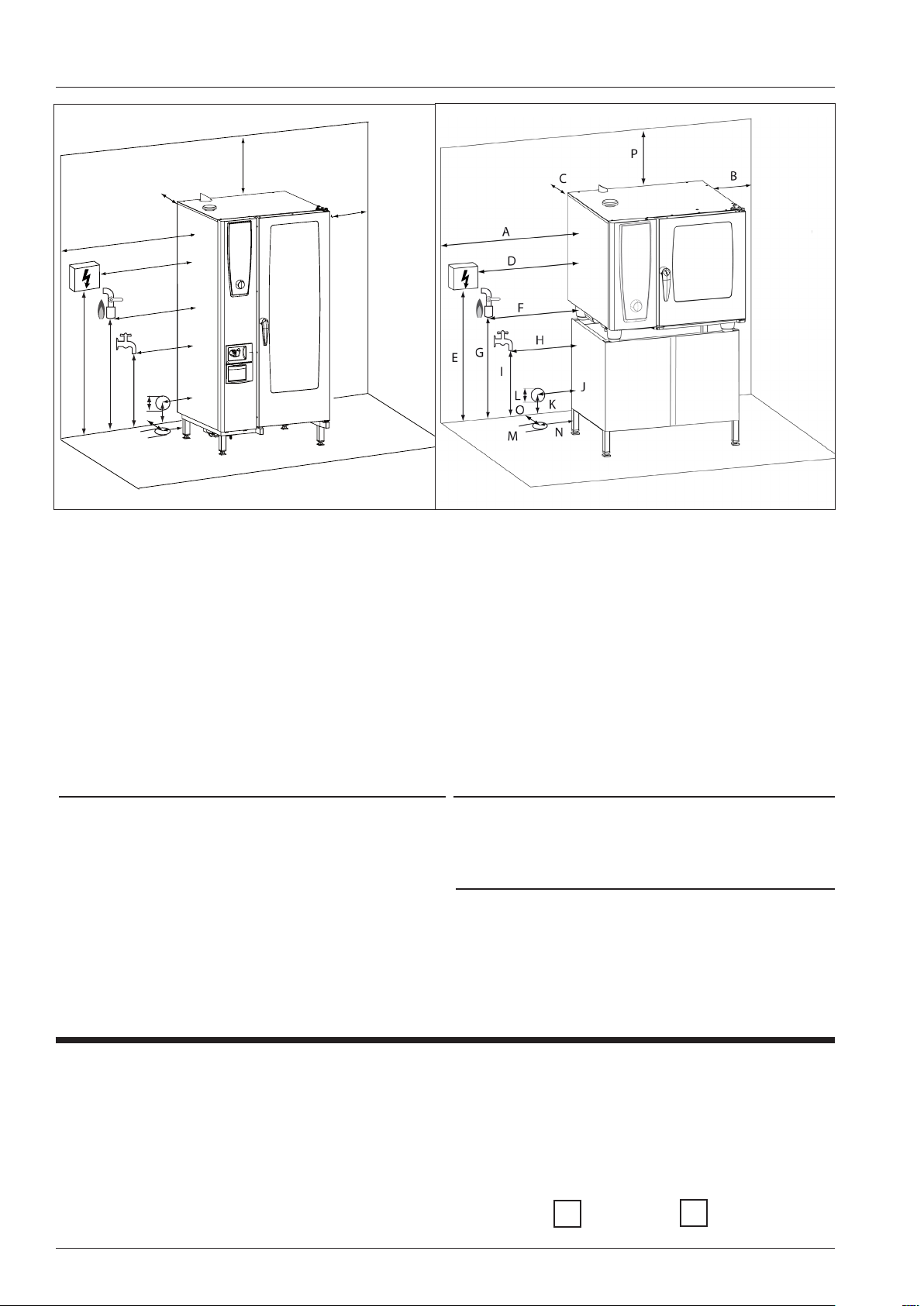
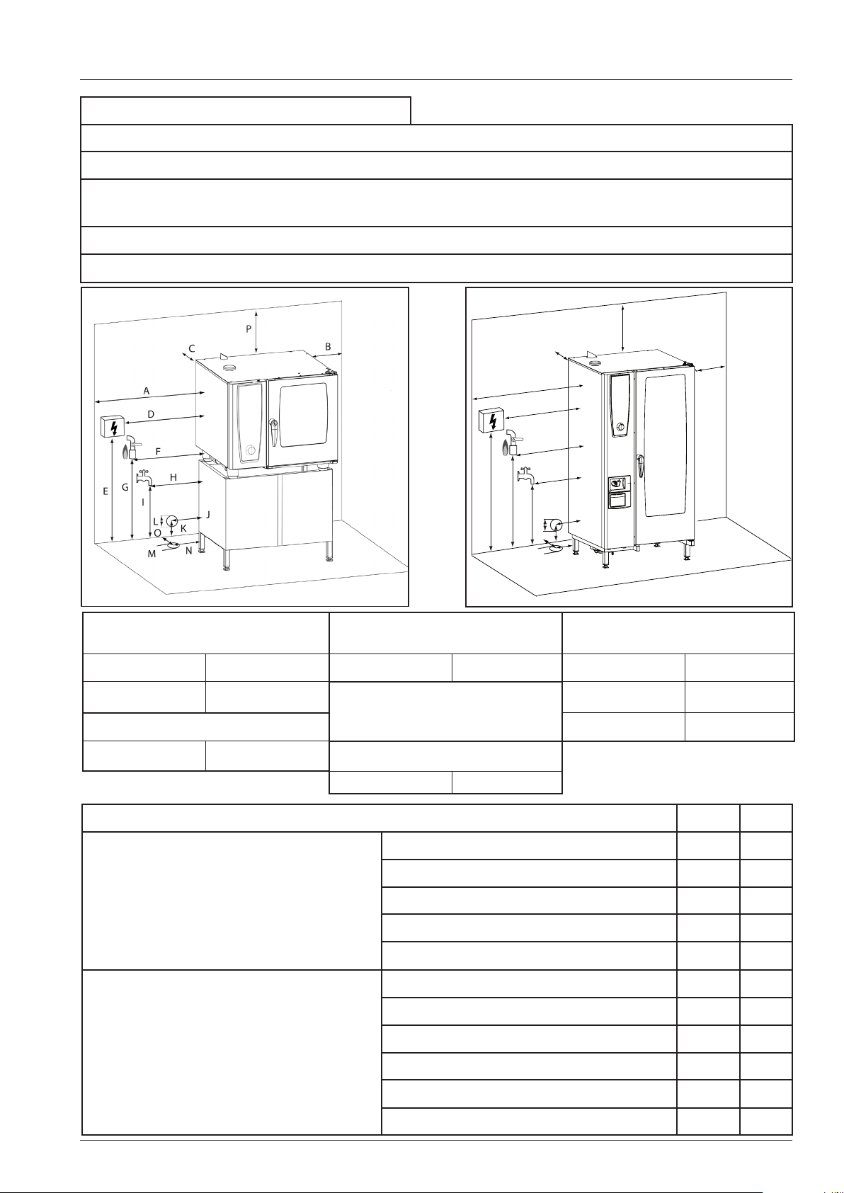
Preinstallation checklist
P
C
A
D
F
G
E
H
I
L
M
J
K
O
B
Please fill in values measured at the site:
For calculating the distances see unit sizes on page 2.
If the connection points are at complete different position show the correct position in
the sketch
Side/top distances
A =
B =
C =
P =
Power supply
D =
E =
3. Elecrical connection
a) Which mains is available (fill in rest)?
1NAC...........
2AC..............
3NAC...........
3AC..............
Gas supply (in case of gas units)
F =
G =
Type of gas connection
Water supply
H =
I =
Drain:
Table model Floor model
J = M =
K = N =
L = O =
b) What fuses are installed in the mains
.................... A
ELCB / Residual current device (30mA) installed?
Yes No
V02 en, Basic_Maintenance_Accessories - 16 -
Page 17
250-300mm
(10 - 12 “)
max. 1m
(3 ft.)
Ø 50mm (2”)
min. 3° / 5%
200-300mm
(8 - 12 “)
3x45°
Ø 50mm (2”)
70mm
(2 3/4“)
max. 1m
(3 ft.)
min. 3° / 5%
Preinstallation checklist
4. Water supply
Yes No
a) Water treatment system installed
If yes, which system_________________________________________
b) Separate water tap for every unit
(Attention: Unit has 3/4” connection)
c) Measured water pressure:_________________________________________________
d) Measured water temperature:______________________________________________
4. Drain
a) Location of drain (fill in page 3)?
b) Material of drain pipe______________
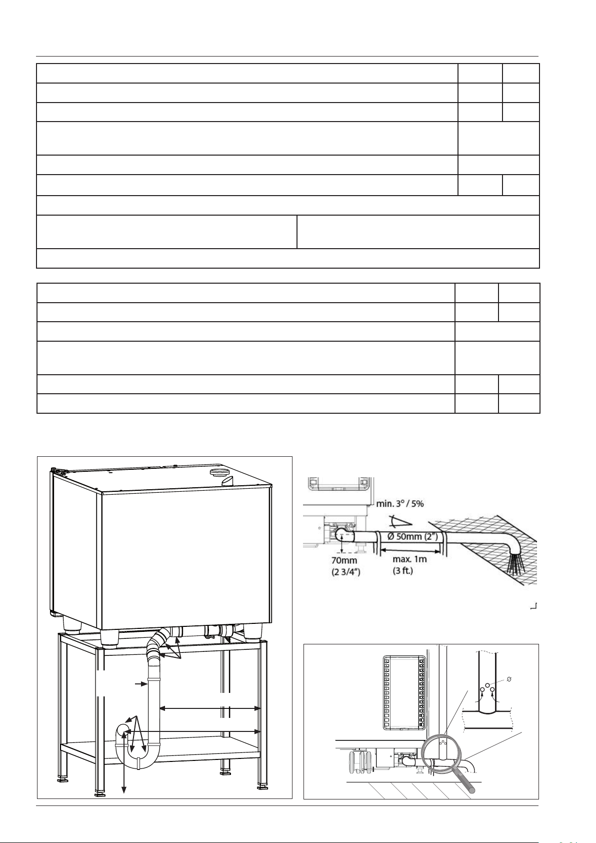
Suggestion for drain connection
Table units Floor units
NOTE:
Only use steam temperature resistant pipes for drain connection, no hoses!
5. Gas supply (in case of gas units)
a) Which gas type is foreseen?__________________________________________
b) Attention: Unit has 3/4” connection
c) Inform customer to discuss room size and flue gas system with local gas authority
yes no
6. Customer was informed about 2 years warranty?
7. Connection set complete (#60.70.464) required?
7. Comments / Notes
- 17 - V02 en, Basic_Maintenance_Accessories
Page 18
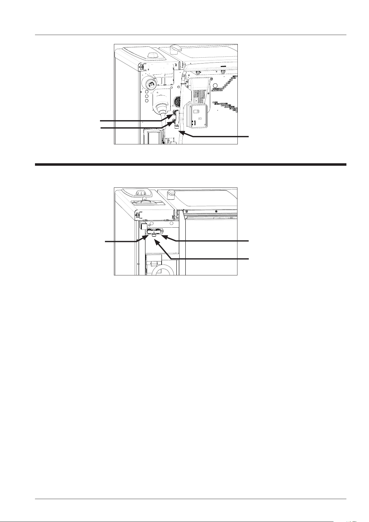
Installation sheet - Electric / Gas units - Electrical connection
Electrical unit connection
61-102
Gas units:
Integrated cable
w/o plug top,
length approx. 2,5m,
Remove left side panel
Loosen 7 mm hex head screw
Opening for power cable
Ground
connection
Electrical unit connection
201-202
Gas units:
Integrated cable
w/o plug top,
length approx.. 2,5m
Remove left side panel
Loosen 7 mm hex head screw
Opening for power cable
Mains supply cable (Observe your local code for maximum cable length)
Terminal connection
L1
L1
L2
grey
L2
L3
grey
L3
Fig. 1
Ye/gn
N
blue
N
61 5x2,5mm² 4x2,5mm² 3x2,5mm²
grey
62 5x4mm² 4x4mm² 3x2,5mm²
101 5x4mm² 4x4mm² 3x2,5mm²
102 5x10mm² 4x10mm² 3x2,5mm²
3NAC400V 3AC440V Gas: 1NAC230V
Ground
connection
ELCB Breaker - residual current device 30 mA recommended
Electrical connection gas units: observe polarity!
All services must comply to local rules and regulations!
V02 en, Basic_Maintenance_Accessories - 18 -
.
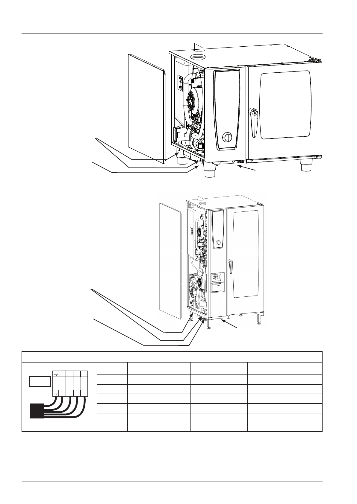
Page 19
Installation sheet - Electric / Gas units - Water connection
Table units
61 - 102
Treated water
Fresh water
Fresh water
(common water supply)
Floor units
201 - 202
Treated water Fresh water
Fresh water
(common water supply)
Dimension water supply hose: 1/2“ pressure hose with 3/4” connection at the unti;
Water pressure:150-600 kPa with 20/25 l/min water quantity
Maximum water temperature for fresh and treated water: 30°C (87°F)
Note:
For selection of water lter please refer to installation manual!
Filter might be necessary in case of:
Cl2 >0,2 mg/l
Cl-- >80 mg/l
very hard water (details: Water info and Installation manual)
All services must comply to local rules and regulations!
- 19 - V02 en, Basic_Maintenance_Accessories
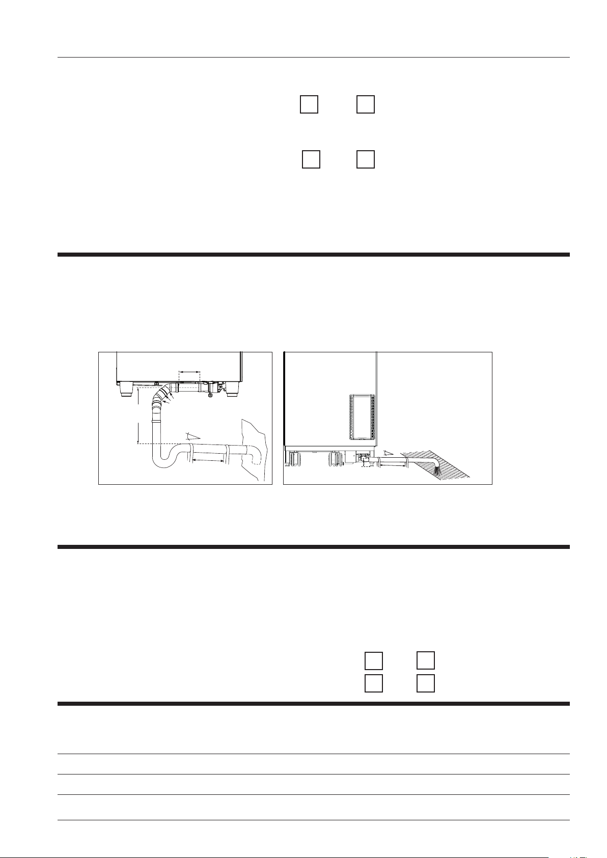
Page 20
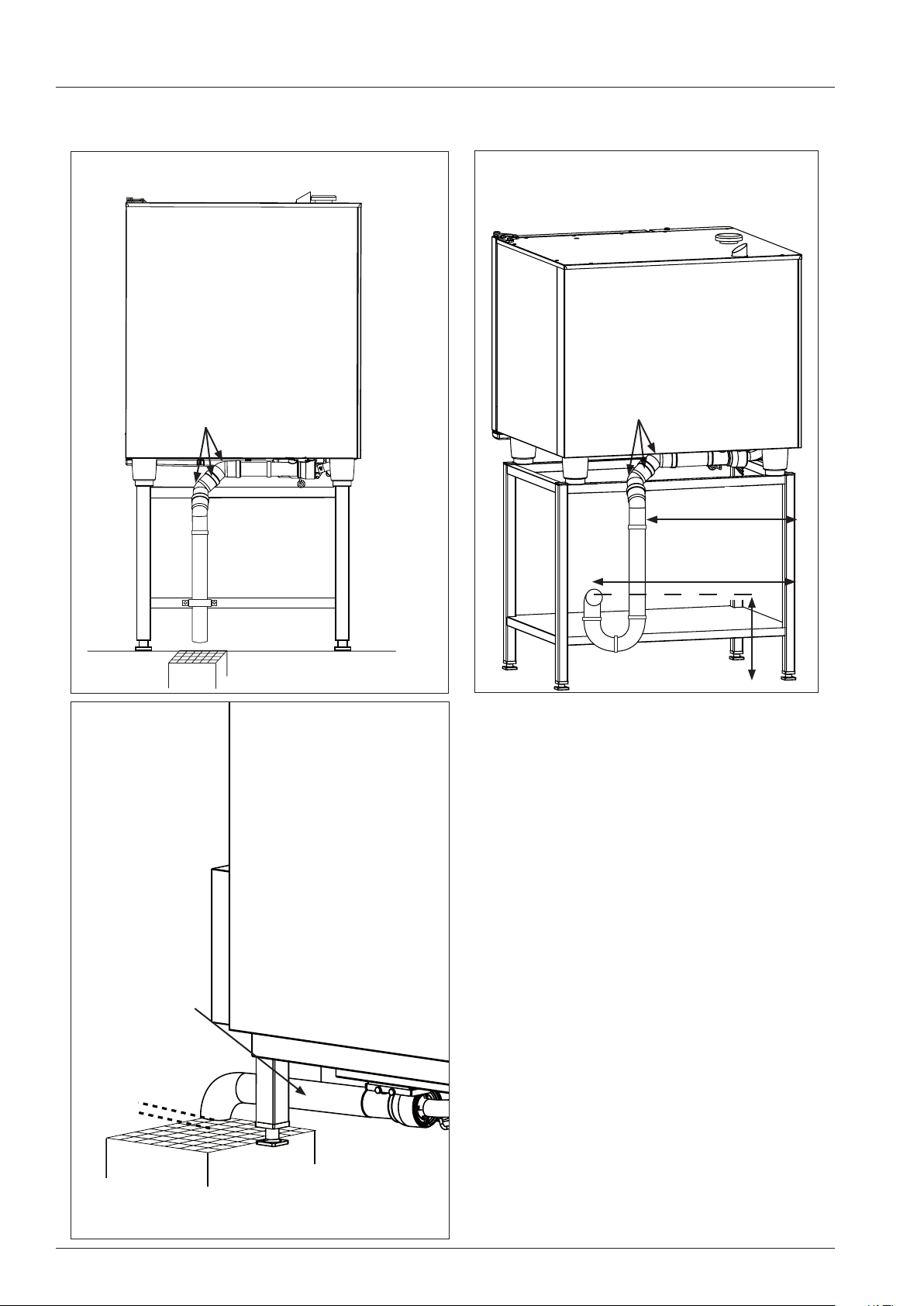
Installation sheet - Electric / Gas units - Drain connection
Drain connection table model
Note: See install manual for leveling unit
Rear view
3x45°
DN 50 HT pipe
weight of piping not to be placed on
unit drain
Fixed to stand
Fixed drain connection table model
Note: See install manual for leveling unit
Rear view
3x45°
DN 50 HT pipe
approx. 550 mm
approx. 720 mm
Air gap per
local code
Floor drain sink with grease trap
Drain connection floor model
Note: See install manual for leveling unit
Side view left
Length approx.
250 mm
approx. 300 mm
Installation kit available # 60.70.464
(Water supply hose
Drain pipe set DN50 HT)
Drain connected
to unit leg
DN 50 HT pipe
All services must comply to local rules and
Floor drain sink with grease trap
V02 en, Basic_Maintenance_Accessories - 20 -
regulations!
Page 21
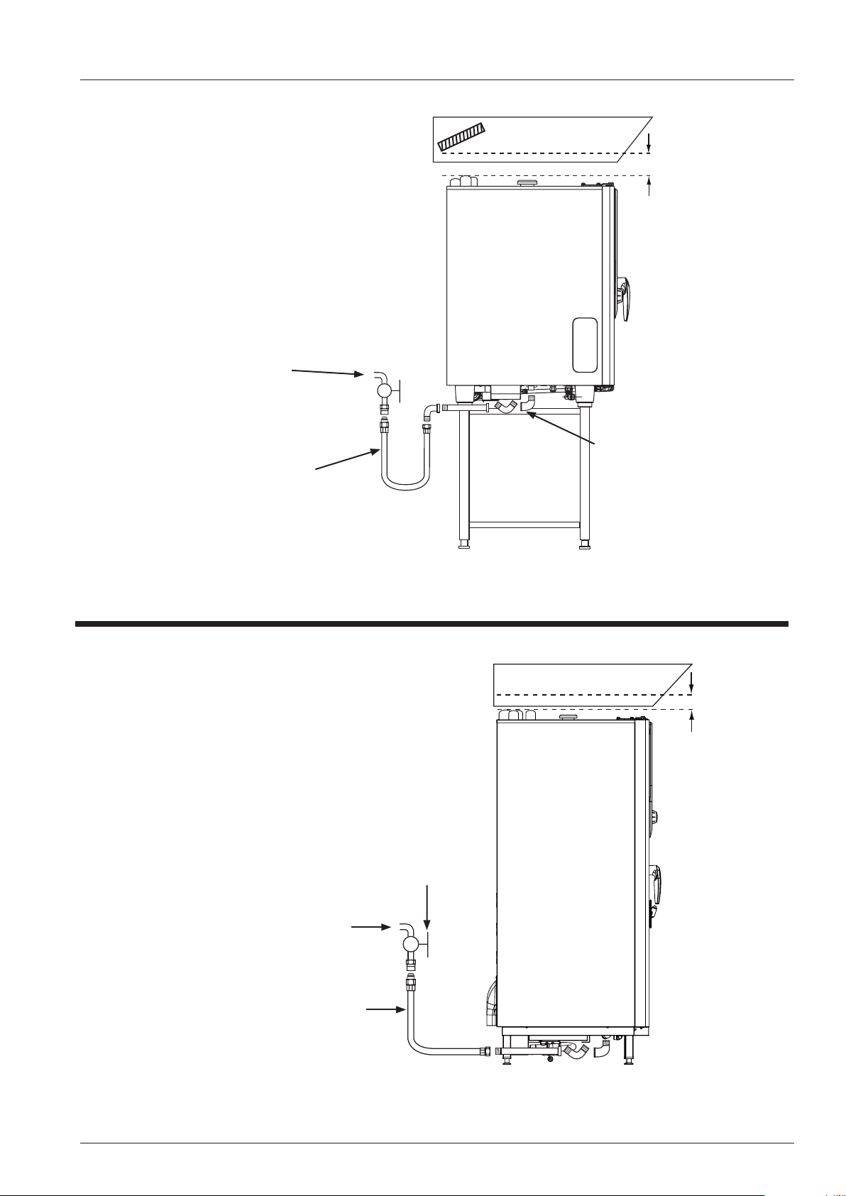
Installation sheet - Gas units - Gas connection
Gas connection 61 - 102
Note: Observe local rules
and regulations
Gas supply
Gas quick
disconnect hose 1,5m
inner diameter ¾“
Unit under
extraction hood
Fat lter
min. 400mm
RATIONAL
Gas stop
valve
Gas connection
Natural gas 1,8 - 2,5 kPa
LPG 2,5 - 5,75 kPa
¾“ for 61 - 202
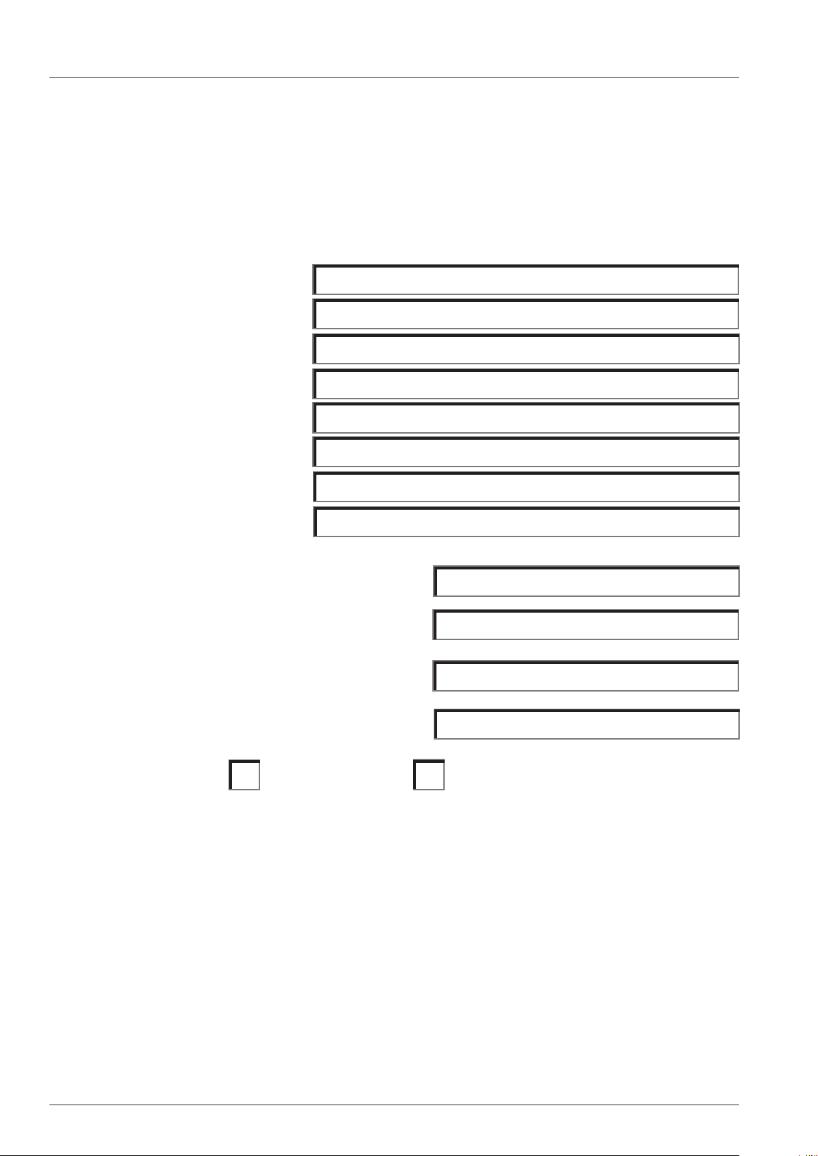
Gas connection 201 - 202
Note: Observe local rules
and regulations
Gas quick
disconnect hose 1,5m
inner diameter ¾“
Unit under
extraction hood
Fat lter
min. 400mm
Gas stop
valve
Gas supply
Gas connection
Natural gas 1,8 - 2,5 kPa
LPG 2,5 - 5,75 kPa
All services must comply to local rules
¾“ for 61 - 202
and regulations!
- 21 - V02 en, Basic_Maintenance_Accessories
Page 22
Installation/Commissioning Checklist
Installation and Commissioning Checklist
To be completed individually for each Rational Combi installation. This checklist is to be completed and
returned to your closest RATIONAL ofce (details are listed on the last page of the operation manual)
within 14 days of installation / commission to validate warranty.
Customer name:
Contact person:
Street:
Town:
Country:
Telephone number:
Fax-Number:
E-Mail:
Serial number of installed units:
Commissioned by company:
Date of installation:
Date of commissioning:
Installation complies does not comply with manufacturers specifications.
Please ll all information required into the embossed elds.
If the measured values do NOT comply with the values in the installation manual please inform the
customer and your Rational dealer.
We conrm the installation was done according to the attached installation checklist, the installation
manual and all national and local codes which ever may apply. The equipment was handed over free of
defects. Operation and maintenance of the equipment was explained.
---------------------------------------------- -------------------------------------
Signature / Date RSP / Dealer Signature / Date customer
V02 en, Basic_Maintenance_Accessories - 22 -
Page 23
Installation/Commissioning Checklist
1. Perimeter clearances
Left side all units (except 201/202 E) minimum:
Left side 201/202 electric units minimum
: 500mm
50mm
Left side recommended for all units for service
or with adjacent heat source: 500mm
Rear side all units minimum
Right side all units minimum
: 50mm
: 50mm
C
A
D
F
G
E
H
I
M
J
L
K
O
P
B
Perimeter clearances Gas supply (in case of gas
units)
Drain: Table models,
floor models
or Combi Duo
A: C: F: G: J: M:
B: P:
Type of gas supply:
K: N:
Power supply L: O:
D: E: Water supply
H: I:
2. Levelling and oor xing YES NO
Mounting surface / stand is level?
Unit is level?
Electric and gas 61, 62, 101, 102
Stand is xed to oor (Gas)?
Unit is secured to mounting surface (Gas)?
Transport trolley is level with unit and stand?
Unit is level?
Unit is xed to oor?
Electric and gas 201, 202
Mounting surface is level?
Trolley stands level inside the unit?
Access ramp is installed?
Unit and trolley extension installed?
- 23 - V02 en, Basic_Maintenance_Accessories
Page 24
Installation/Commissioning Checklist
3. Water connection YES NO
Water shut off valve available for each unit (also for each Combi Duo unit)?
Water shut off valve accessible by operator?
Measured water pressure at the water inlet of the unit
All units: minimum 150KPa (1,5 bar), maximum 600 KPa, (6 bar)
bar
Measured water temperature at the water inlet of the unit °C
Water ltration / treatment system installed?
Manufacturer and type of water lter / treatment system:
Measured water hardness
at lter inlet ____________ppm/l
Measured water hardness
at lter outlet ____________ppm/l
1°dH = 1,25°e = 1,78°f = 17,8 ppm/l = 0,178 mmol/l
4. Drain YES NO
Steam temperature resistant pipe, no exible hose? (I.e. drain kit # 8720.1031)?
Drain table units: P-trap or open drain? (please ll in)
Drain oor units: P-trap or open drain? (please ll in)
(open drain MUST NOT end underneath unit)
Separate drain for each unit (also Combi Duo units)?
Additional vent pipe installed
Example table units
Rear view
3x45°
DN 50
HT pipe
approx. 550 mm
3x90°
approx. 720 mm
Example oor models
Example additional vent pipe
8 mm
1/8"
approx. 300 mm
V02 en, Basic_Maintenance_Accessories - 24 -
Page 25
Installation/Commissioning Checklist
5. Electrical connection - Observe Local and National Codes! YES NO
Indicated voltage on data plate
Available voltage on site
Measured voltage L1- L2:_______V L1 - L3: _______V L2 - L3: _______V
L1 - N: _______V L2 - N: ________V L3 - N: _______V N - PE: ______V
Unit connected to equipotential bonding?
3 phase breaker installed?
Power switch / outlet accessible from front by operator?
Installed fuse rating?
Isolation/discharge current measurement carried out?
Amp draw at 100% steam heating L1:____A L2: ____A L3: ____A
Amp draw at 100% hot air heating L1:____A L2: ____A L3: ____A
Amp draw gas units A
6. Gas connection - Observe Local and National Codes! YES NO
Available diameter of gas line to each unit (all units 3/4“ minimum):
Flue gas and fresh air system sufciently dimensioned?
Gas pressure regulator installed?
Individual gas shut off valve installed for each unit?
Gas shut off valve accessible by operator?
Indicated gas type on data plate:
Available gas type on site:
Measured gas pressure with unit switched off (static gas pressure): mbar
Measured gas ow pressure with unit switched on,
when all other gas consumers in the kitchen are switched on (dynamic gas pressure):
mbar
Altitude above / below sea level? m
Flue gas analysis carried out (write down values in below list)?
Values at max. RPM Values at min. RPM
Burner
CO
2
CO
Flame current
CO
2
CO
Flame current
Steam ______% ______ppm ______μA ______% ______ppm ______μA
Hot air
top
Hot air
bottom
- 25 - V02 en, Basic_Maintenance_Accessories
______% ______ppm ______μA ______% ______ppm ______μA
______% ______ppm ______μA ______% ______ppm ______μA
Page 26
Installation/Commissioning Checklist
7. Exhaust / vent hood YES NO
Exhaust / vent hood installed?
Serial number of installed UltraVent or extraction hood
In case of gas units is hood interlocked with gas supply?
Free space between top edge of unit and lower edge of exhaust hood / ceiling cm
8. Function test / commissioning YES NO
All electrical connections and plugs tight and in accordance with local regulation?
All water and drain connections tight and not leaking?
All modes operational?
All additional functions / features operational?
Self test completed successfully?
Customer was informed about 2 years warranty?
Customer advised in basic operation?
Customer advised in daily cleaning routine incl. door gasket?
Customer advised in preventative maintenance
(changing air inlet lter, door gasket, etc)
9. Miscellaneous YES NO
Service data downloaded?
Photos of installation taken?
V02 en, Basic_Maintenance_Accessories - 26 -
Page 27
Preventive maintenance
Please ll in one form for every installed unit.
This checklist contains all works that have to be carried out during a maintenance.
Customer address Name
Company
Street
ZIP / Post code
City
Country
Telephone
Serial number of the unit
Software Version:
Checks / maintenance work scope Comment
Installation (conforms to install instruction) YES NO
All gas units and units 201-202 xed to oor
Water connection
Manufacturer of water treatment system
Drain
Gas connection
Electrical connection
Cabinet door (Functional)
Door lock
door catch
Door mounting / screws
Fastening of inner glass pane
Door gasket (steam tight in steam mode)
Door contact (door alignment and switch)
Trolley gasket (201-202)
Trolley castors (201-202)
Interior cabinet (Functional)
Interior cabinet light
Core temperature sensor
Cabinet sensor
Clima ap / valve tight
Air bafe
Moistening nozzle clean
Sieve installed correctly
Any corrosion on the unit or accessories
YES NO
Yes NO
- 27 - V02 en, Basic_Maintenance_Accessories
Page 28
Preventive maintenance
Checks / maintenance work scope Comment
Water supply - drain (Functional) YES NO
Dynamic water pressure KPa
All water joints leak tight
Function of hand shower and retraction system
Connection of drain conforms to install. instruct.
Quenching - quenching box clean
Function of drain valve (only SCC)
Steam generator
(Functional) YES NO
Steam generator leak tight
SC-Pump - ushing
Descale steam generator - if necessary
If descaled, was new lling volume evaluated?
Level electrode clean
Electric parts
(Functional) YES NO
Unit connected to earth bonding
Wire insulations undamaged
All electrical connections xed and tight
All contacts of main contactor free (not stuck)
Amp draw hot air (at 100%) electric units
Amp draw steam (at 100%) electric units
L1:___ A; L2:___ A; L3:___ A
L1:___ A; L2:___ A; L3:___ A
Max temperature of pcb °C
Gas components - Hint: Gas components must be maintained annually!
(Functional) YES NO
All gas connections leak tight
Cleaning of burner head (TI 03-2007) index E-G
Cleaning of ignition electrode
If necessary change all blower gaskets
Gas blower premix chamber free of fat and dust
Visual inspection of external ue gas venting
Dynamic ow pressure (all gas units in operation) mbar
CO
max steam - ame current - CO ppm % µA ppm
2
CO
min steam - ame current - CO ppm % µA ppm
2
CO
max HA top - ame current - CO ppm % µA ppm
2
CO
min HA top - ame current - CO ppm % µA ppm
2
CO
max HA bottom - ame current - CO ppm % µA ppm
2
CO
min HA bottom - ame current - CO ppm % µA ppm
2
Length of CO
screw of gas valve in mm
2
Steam HA top HA bottom
Make sure the gas compensation hose (hot air and steam) is not kinked and is properly xed in its
correct position.
V02 en, Basic_Maintenance_Accessories - 28 -
Page 29
Preventive maintenance
Checks / maintenance work scope
Control panel (functional)
Check closing mechanism
Control panel gasket and panel overlay
Plug for opening control panel in place
Dials
Mode switch (CM)
Temperature and time control
Core probe functional
LED indicators
PCB visual check (water marks etc)
Air lter clean and cooling fan ok
Exhaust hood / Ultravent
Exhaust hood or Ultravent installed
Hood and lighting operational
(Functional) YES NO
Comment
YES NO
Serial number of Rational exhaust hood
Free space between top edge of unit and
lower edge of exhaust hood / ceiling
Function test / commissioning
All electrical connections and plugs tight
All modes operational
All valid service error codes checked
All max. values of the sensors reset
Humidity control functional
Customer advised in basic operation and
programming
Customer advised in preventive maintenance
(Changing air lter, cleaning door gasket)
Service-telephone number entered
Chef Line-telephone number entered
Demonstration CleanJet
YES NO
cm
Service Data and HACCP Data copied to
USB stick.
Electrical safety
Electrical safety measures in accordance
with local standards
Name RSP Technician: Date and sign Customer: Date and sign
- 29 - V02 en, Basic_Maintenance_Accessories
Page 30
Instruction for manual descaling
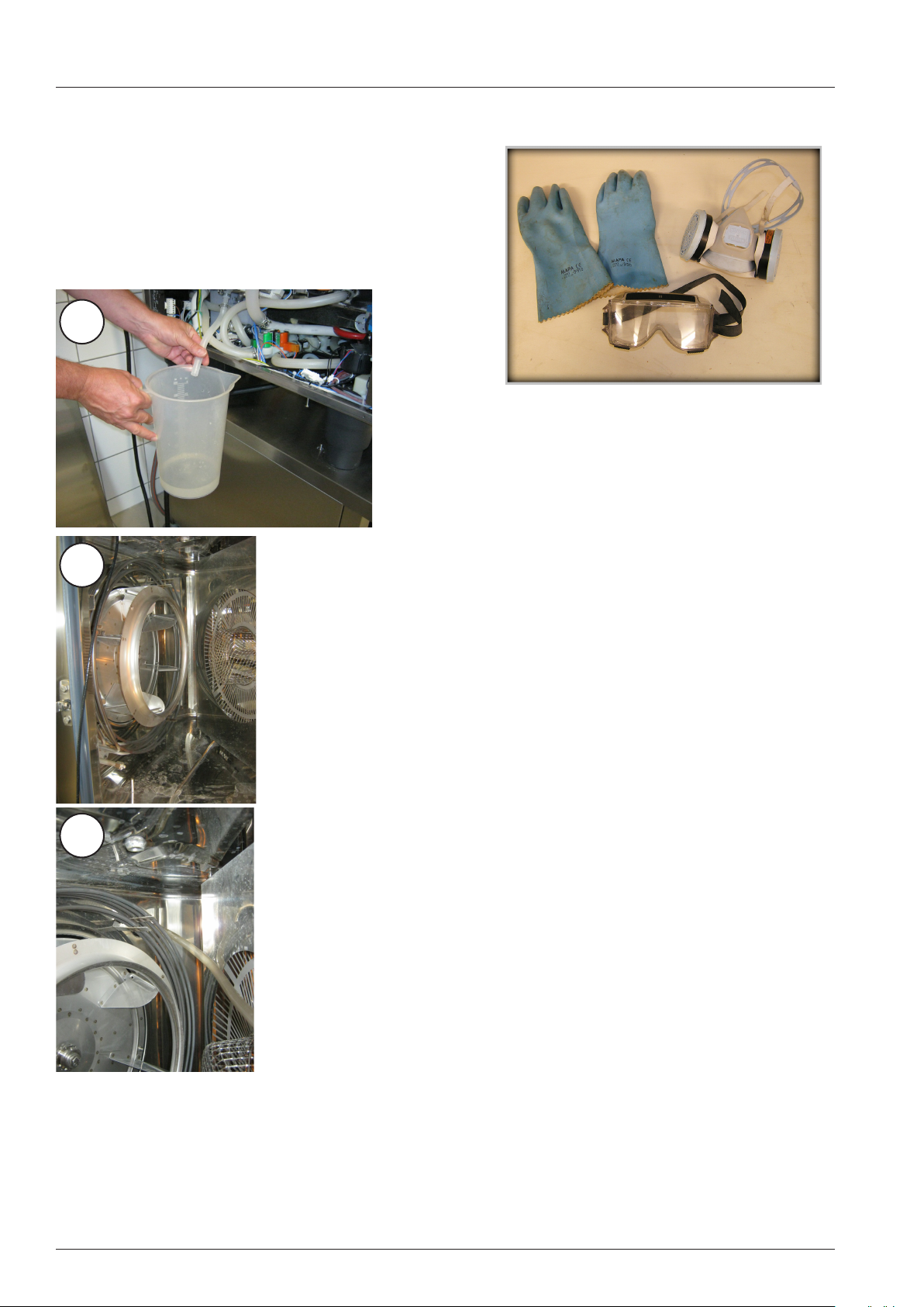
Protective clothing and tools required:
- Protective clothing:
Goggles, gloves, apron
- Container with descaler
- Foot pump (6004.0203)
2
3
1. SCC or CM shall only be descaled when the cabinet temperature is below 40°C (104°F)
Start cool down if required.
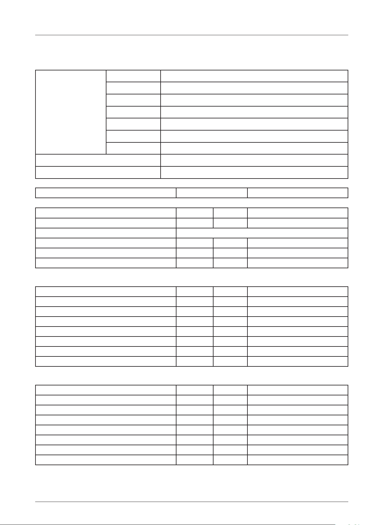
2. Empty and rell steam generator to cool it down.
Now empty steam generator manually into a
bucket and measure the volume of water drained
from the steam generator.
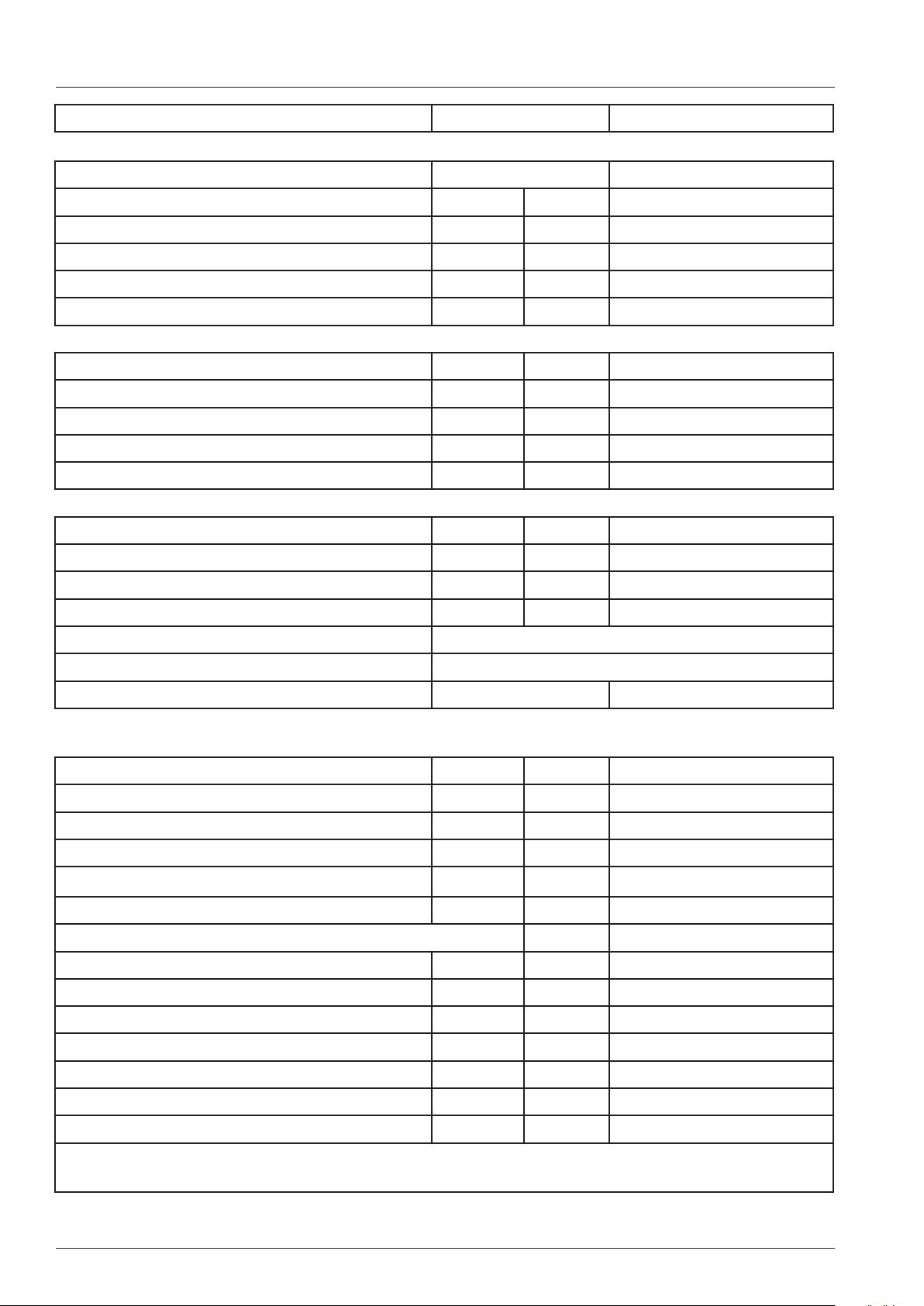
3. Descaler must ONLY be lled via the steam inlet
port found inside the interior cabinet!
Remove hinged rack (trolley) and swing air bafe
open.
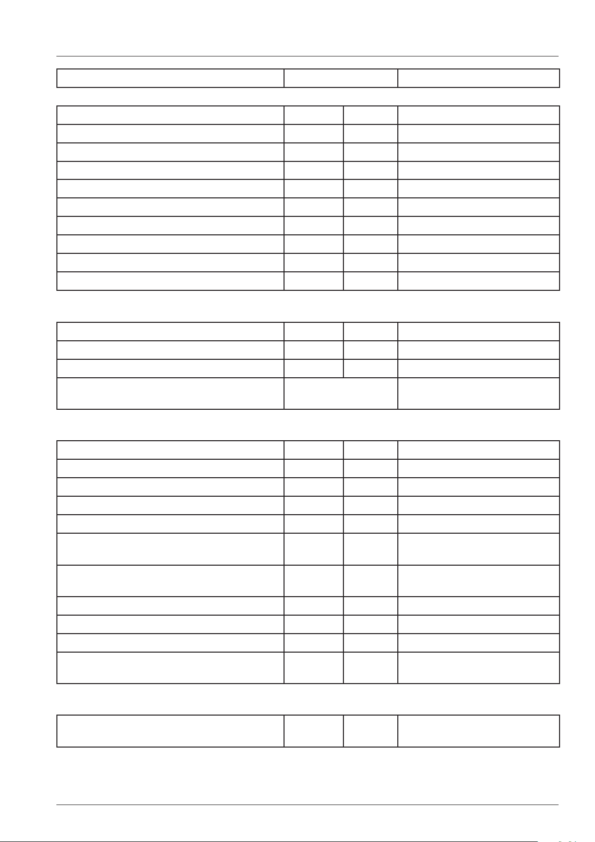
4. Insert hose of descaler pump into steam inlet port
4
inside interior cabinet.
Do NOT ll through level electrode opening!
Damage to other components may occur!
5. Place descaler can into cabinet.
6. Insert the other hose end into can. Make sure the
red rubber plug rmly sits in the can opening
V02 en, Basic_Maintenance_Accessories - 30 -
Page 31

Instruction for manual descaling
5-7
7. Fill the recommended quantity SLOWLY into the
steam generator.
Caution:
Chemical may react violently with scale
and cause foaming back though steam
inlet port!
8. After lling remove pump and descaler can from
cabinet and rinse both cabinet and pump
thoroughly with fresh water.
8
10
9. Allow enough time for descaler to react
15 % concentration: ~ 1,5 hours,
30 % concentration: ~ 45 minutes
10. Carefully remove moistening nozzle and descale
in separate container with descaler liquid.
Isolate unit from power supply!
11. Open left side panel, remove quenching box cover
and remove any scale / deposits from quenching
box and cover.
After reassembly ensure no leaks are present.
12. Reconnect unit to power. After given time (pt.9)
use function test to drain liquid from steam
generator.
13. Let steam generator ll and drain 3 times.
11
14. Operate the unit for 15 min. in steam mode.
15. Rinse cabinet again with hand shower.
16. Isolate unit from power and drain steam genera-
tor manually to measure the new volume without
scale.
17. SCC only: In Basic Settings Pos. 9
press and hold for 5 seconds
“Reset after manual descaling”
Non compliance with this instruction can cause damages to the unit!
- 31 - V02 en, Basic_Maintenance_Accessories
Page 32

V02 en, Basic_Maintenance_Accessories - 32 -
Page 33

Additional information for manual descaling
In order to determine the amount of scale inside the steam generator manually drain and measure the
volume of water from the steam generator.
The steam generator should be descaled when less than the below listed volumes are drained from
the steam generator:
1 liter = 0.264gal (US); 1gal (US) = 3,78 liter; 4,5 liter = 4,5 x 0,264 = 1,19 gal(US)
SCC/CM
Electric units
SCC/CM
Gas units
CPC/CM
Electric units
CPC/CM
Gas units
Line
Classic-
Gas units
Unit size Descale if less
than below volume
is drained
61 2,7 l 3,6 l 3,6 l
62 4,5 l 6,0 l 6,0 l
101 4,7 l 6,2 l 6,2 l
102 6,4 l 8,5 l 8,5 l
201 6,8 9,0 l 9,0 l
202 8,7 l 11,6 11,6
61 Gas 3,0 l 4,0 l 4,0 l
62 Gas 4,5 l 6,0 l 6,0 l
101 Gas 5,3 l 7,0 l 7,0 l
102 Gas 6,8 l 9,0 l 9,0 l
201 Gas 6,0 l 8,0 l 8,0 l
202 Gas 8,3 l 11,0 l 11,0 l
61 2,4 l 4,0 l 3,2 l
101 4,0 l 7,0 l 5,0 l
102 6,5 l 11,0 l 7,7 l
201 6,9 l 12,0 l 8,1 l
202 9,6 l 15,0 l 11,0 l
61 Gas 2,6 l 4,5 l 3,6 l
101 Gas 4,8 l 8,0 l 6,0 l
102 Gas 4,9 l 8,0 l 6,1 l
201 Gas 4,9 l 8,0 l 6,1 l
201 Gas 7,2 l 12,0 l 8,4 l
CM 62 Gas 3,5 l 6,0 l 5,5 l
CM 101 Gas 3,5 l 6,0 l 5,5 l
CM 201 Gas 7,0 l 12,0 l 11,0 l
CD/CM/CC 6 2,5 l
Required volume
of descaler
Volume of
clean steam
generator
CD/CM/CC 101 4,0 l
Line
Classic-
electric units
- 33 - V02 en, Basic_Maintenance_Accessories
CD/CM/CC 201 7,0 l
CD/CM/CC 20 10,0 l
Page 34

User instruction electrical descaler pump
The descaler pump 60.70.409 (230V) and 60.70.497 (110V) must
only be used to ll chemical part number: 6006.0110 into steam
generators of equipment bearing either of the following marks on the
data plate:
When working with chemicals, i.e. aggressive cleaning materials, always wear
protective clothing, goggles, face mask and gloves!
Please observe all information given on the Material Safety Data Sheet of your
descaling chemical!
Only personnel specially trained on handling hazardous materials shall follow
the instructions below!
Descaler shall ONLY be lled through steam inlet port inside cabinet!
1. Unlatch the left side hinged rack and the air bafe. Swivel them towards the right side.
2. Insert the pump hose marked with rings into the steam inlet port at the rear left top
corner of the interior cabinet.
The hose must be inserted at least to the following marking rings:
All electric heated units 3rd Ring 43cm (17“)
CM/SCC 61 and 62 Gas: 1st Ring 17cm (6,5“)
CM/SCC 101 and 102 Gas: 2nd Ring 31cm (12“)
CM/SCC 201 and 202 Gas: 3rd Ring 43cm (17“)
To prevent the hose from slipping out of the steam inlet port secure the hook
which is attached to the hose at 100cm (40”) from end of the hose onto the
air bafe cut out for the core probe as indicated.
3. Insert the suction hose of the pump into the descaling liquid bottle. Please observe the
below listed volume of descaler used for the different model sizes. Given volumes
are average and dependend on scale build up inside the steam generator.
Descaler volume for electric units (volume in gal given as US gallons!)
SCC/CM 61 SCC/CM 62 SCC/CM 101 SCC/CM 102 SCC/CM 201 SCC/CM 202
3,6 L / 0,95gal 8 L / 2,1gal 8 L / 2,1gal 11,5 L / 3 gal 12 L / 3,1gal 14,6 L / 3,85gal
Descaler volume for gas units SCC and CM
SCC/CM 61G SCC/CM 62G SCC/CM 101G SCC/CM 102G SCC/CM 201G SCC/CM 202G
6 L / 1,6gal 8 L / 2,1gal 9 L / 2,4gal 11 L / 2,9gal 10 L / 2,6gal 14 L / 3,7gal
V02 en, Basic_Maintenance_Accessories - 34 -
Page 35

User instruction electrical descaler pump
4. Close cabinet door as far as possible and ll the above mentioned volume of descaler at 10 sec
intervals into the steam generator
NOTE: Descaling liquid can react very violently with the scale inside the steam generator!
Should any foam appear at the steam inlet port stop lling and wash the interior cabinet
with fresh water.
5. After lling the required volume remove the hose from the steam inlet port. Pump the remaining
liquid from inside the hose back into the descaler container bottle
6. Flush and rinse pump and pump hoses with fresh water.
Caution: not rinsing can cause internal corrosion of the pump.
7. Rinse the cabinet with fresh water.
8. Follow the additional instructions detailed in the users manual for completing the descaling proc-
ess.
Non compliance this instruction can cause damages to the unit!
- 35 - V02 en, Basic_Maintenance_Accessories
Page 36

Daily care - Unit and Door Gasket
Exterior surface of unit:
The exterior surface of the unit shall only be cleaned with a wet soft cloth. Aggressive or scouring
cleaning agents are not allowed.
Hosing down the unit with water jet or pressure cleaner is also not permitted.
Door glass:
The inner door glass can be opened by releasing the 2 spring clips. Use only a wet soft cloth for cleaning of this surface.
Aggressive or scouring cleaning agents are not allowed.
Door gasket:
Temperatures of 220°C or higher together with continued use of
grilling processes demand cleaning of the door gasket several times
per day, ideally after every loading.
Carefully wiping down the inner and outer side of the door gasket
will extend the life time of the gasket considerably.
Please do NOT use any aggressive, scouring or vinegar-based
cleaning agents for this purpose.
Please do NOT run the unit idle at high temperatures for stand by
purposes.
Drain of door drip pan
Please make sure the drain of the door drip pan is not blocked by fat or other foreign matter.
Rinse daily with water from the hand shower.
Air lter:
Depending on the kitchen environment the air lter should be
changed every 3-12 months.
The air lter can be cleaned in a commercial dish washer too.
The air lter for unit sizes 61 - 102 is located under the front panel
and can be removed by simply pushing the lter frame backwards.
The air lters of units 201 - 202 are located at the rear left side of
the unit and can only be accessed by unlocking the covering frame
using e.g. a screw driver. This must not be done by the customer!
Make sure the air lter is properly engaged again after replacing.
V02 en, Basic_Maintenance_Accessories - 36 -
Page 37

Instruction for manual cleaning
For manual cleaning observe the following:
• Follow the safety instructions on the spray bottle and cleaner canister.
• Use only genuine cleaning agents and the genuine hand spray gun (article no.: 6004.0100)
from the unit manufacturer.
• Never leave hand spray guns pressurised.
• Never spray other people, animals or objects
Cleaning steps:
1. In case of a high degree of soil inside the cooking cabinet rst select steam mode at 90°C and run
unit for 10 minutes. Afterwards ush the cabinet with the hand shower.
2. Check cooking cabinet temperature
Should temperature inside the cooking cabinet exceed 60°C, then cooking cabinet must be cooled
down below 60°C. To cool down the unit use the function “cool down”.
Hint:
If cleaner is sprayed into a hot cooking cabinet (temperature above 60°C), this will cause permanent
staining. To remove staining aggressive chemicals are necessary.
3. Spray cleaner into cooking cabinet
Swivel hinging rack and air baffle to the middle of the cooking cabinet.
Spray cleaner to the space behind the air baffle, into the cooking cabinet, the inner side of the door
and the door gasket.
Once complete bring air baffle and hinging rack to original position and lock them.
Warning:
Aggressive chemical fluid – risk of chemical burns.
It is essential that you use: protective clothing, safety goggles, gloves, face mask and the unit manufacturer‘s hand spray gun.
4. Allow cleaner to react for 20 minutes.
5. Select steam mode. Cooking cabinet temperature 90°C, running time 20 minutes.
6. After the running time has elapsed, spray the cooking cabinet thoroughly with the hand shower.
Check cleaning result, if necessary repeat steps 3 to 6.
7. Wipe door gasket inside and outside with a wet cloth.
8. Select hot air mode, cooking cabinet temperature 160°C running time 15 minutes.
9. If unit will not be used after cleaning switch off unit and leave cooking cabinet door ajar.
- 37 - V02 en, Basic_Maintenance_Accessories
Page 38

Ultravent (UV)
Ultravent Ultravent Plus
Serial number:
ET1UVA11095000126
ET2PA11095000133
old:
6606 2 0111 2120
from 09-2011
Energy, Duo unit size model Version Year Month Serial number
E = Electric T1 - 61 / 101
G = Gas T2 - 62 / 102
D = Combi Duo
only electric
F1 = 201
F2 = 202
U = UV
P = UVPlus
D = Extraction hood
A- Basis Version 11 09 5000126
until 09-2011 - Type Year Revision Day Month number
Ultravent (UV) 11 1 01 11 2120
66 61/101 Electric 1= contactor control
68 61/101 Electric, Combi-Duo 2= BUS control
70 61/101 Gas
72 62/102 Electric
73 201 Electric
74 61/101 Elektro Version US/Can 1= contactor control inside UV
77 62 Elektro Version US/Can 2= contactor control outside UV
Venting hood (EH):
60 61/101 Electric
62 61/101 Electric, Combi-Duo
64 61/101 Gas
08 62/102 Electric,
Air circulation Ultravent:
V02 en, Basic_Maintenance_Accessories - 38 -
Page 39

Ultravent
Ultravent / Ultravent Plus
The Ultravent has to be connected to a separate power supply.
The Ultravent will be started by the BUS signal. (Combi Duo: The Ultravent is connected to the BUS
system of both units.)
The PCB Service part is always equipped with 2 Minit BUS connections and 2 RJ45 BUS connec-
tions.
In case the power supply to the Ultravent or the BUS connection is faulty, Service 35 (SCC_WE) or
E35 (CM_P) will be indicated.
If the Ultravent is nally disconnected, it must be deactivated in “Basic Settings”.
Ultravent
As soon as the BUS sends the signal „unit is running“ the Ultravent is running on low speed. When
the cabinet door is opened, it will switch to high speed. 1 minute after ending of cooking program the
Ultravent will switch off.
A Ultravent for Combi Duo and Ultravent Plus has 2 fan motors (ref. to circuit diagram below)
Ultravent und SCC / CM Index E-G
The BUS controlled UV is only supported starting with software version 01-07-11 (SCC)
and C1.07.01 (CM) accordingly
Ultravent Plus
The UV Plus is equipped with 2 lters. The state of the lter is monitored by differential pressure
switches and positioning switches and indicated by 1 LED each.
Filter 1 (pre lter) is located directly behing the front grease lters. In order to extend the life of the
main lter (2) and should be changed when the middle LED (LED1) is activ.
Filter 2 (main lter) is located on top of the Ultravent. This lter should be changed when the right LED
(LED2) is activ.
Should any of the positioning switches remain open (lter not inserted) the left LED „ERROR“ will show
red.
Circuit diagram Ultravent Combi Duo (2 fan motors):
- 39 - V02 en, Basic_Maintenance_Accessories
Page 40

4
--
Circuit diagram Ultravent Plus:
Circuit diagram Ultravent Version USA:
F1
6,3A
S1
3
4
F3
115V
315mA
F2
315mA
115V
T1
24V
K3
-
1
2
-
-
K1
A1
A2
H1
K5
A1
B1A1A2
A2
S6
K3
-
-
-
115V 0V
T2
-
AC
-
AC
- +
K5
K4
-
X0
+
-
A1
A2
-
- 0V
-
+24V DC
-
161518
Magnet
Y1
K4
X23
1
2
L1
W26
N
PE
-
S4
-
5
K1
12 14
-
M
~
M1
215W
11
-
K3
11
12
1
2
K1
F2
161518
-
3
-
F1
3
N
N
K2
A1
A2
A1
A2
-
-
PE
PE
S5
11
K2
14
-
F1 Fuse 6,3 A
F2 Fuse 315 mA
F3 Fuse 315mA
K1 Fan relay
K2 Mode relay
K3 Warning relay
K4 Magnet relay
K5 Timing relay
M1 Fan motor
S1 Mode switch
S4 Charcoal filter switch 1
S5 Charcoal filter switch 2
S6 Pressure sensor filter
T1 Transformer 115V/24V
T2 Transformer 115V/24V
Y1 Magnet
V02 en, Basic_Maintenance_Accessories - 40 -
Page 41

CombiDuo, Thermo cabinet
The following units (manufactured after 04-2004) can be combined
as a CombiDuo:
• 61 (top) on top of 61, 101, 62 or 102
• 62 (top) on top of 62 or 102
• 101 (top) on top of 62
To order a mounting kit for Combi Duo you must select the energy of
the lower unit (electric or gas) and one of the following base options:
1. Movable (front - back) on 40mm rollers
2. On castors (2 xed - 2 swivel)
3. On 150mm legs
The combination 101 on top of 61 shall not be assembled. Reason is the unfavourable center of gravity.
Only the combination 61 on 61, 61 on 101 and 62 on 102 in the base
option “movable” have the top GN runner not higher than 1600mm
under the condition the lower unit is an electric version unit.
Installation instruction you can nd on the Service DVD 7007.3080 or
on the Service Web site.
Thermo cabinet
The Thermo cabinet is available for unit sizes 61/101 and 62/102.
The heating elements are located inside the middle dividing wall.
This appliance must only be used in catering
establishments to keep plates and GN containers
warm!
Due to hygienic regulations the storing of food is
not allowed!
- 41 - V02 en, Basic_Maintenance_Accessories
Page 42

Condensation breaker steam
In order to guide the steam from the vent pipe of the quenching box
into a ventilation hood without affecting the humidity control we have
created 3 new condensation breaker as an accessory.
SCC_WE and CM_P 61, 62 and 101: 60.72.591
SCC_WE and CM_P 102: 60.72.592
SCC_WE and CM_P 201 and 202: 60.72.593
All pipes of the condensation breaker are made of stainless steel
for use also on gas units.
These condensation breaker can no be used on older units
of the SCC line
Draft Diverter Gas units
When discharging the ue gases of a gas unit into a chimney, a draft diverter type B13 must be used.
This draft diverter is equipped with a safety thermostat, which will interrupt the power supply to the
ignition box and stop the operation of the unit when the temperature in the draft diverter is above the
maximum allowable temperature.
8 different draft diverter and draft diverter with silencer are available:
Draft diverter Gas units 61 type B13 70.00.737
Draft diverter Gas units 101 type B13 70.00.757
Draft diverter Ultravent Gas units 61 type B13 70.00.759
Draft diverter Ultravent Gas units 101 type B13 70.00.793
Draft diverter with silencer:
Draft diverter with silencer Gas units 62 Typ B13 70.00.768
Draft diverter with silencer Gas units 102 Typ B13 70.00.769
Draft diverter with silencer Gas units 201 Typ B13 70.00.770
Draft diverter with silencer Gas units 202 Typ B13 70.00.771
V02 en, Basic_Maintenance_Accessories - 42 -
Page 43

Sicotronic
Sicotronic stands for energy management systems and energy optimization plants for electro-thermal
and general electrical devices in a large-scale catering establishment.
Industrial customers pay electricity rate according to a maximum of Power consumption. Should the
amp draw exceed a set maximum the power supply company will charge a higher premium per KWh.
In order to avoid this current peak a surveillance system like Sicotronic is connected to the Power
meter which will disconnect individual consumers for a certain time according to a preset priority list.
For this purpose these consumers are connected to this system with a signal “energy demand ON”.
The feed back signal will be interrupted if needed.
The Sicotronic option must be ordered separately.
When retrotting Sicotronic, a new service part PCB is needed for SCC_WE and CM_P.
Ethernet Connection
SCC_WE:
Ethernet connectivity is a standard feature of all SCC_WE units. The PCB is equipped with an ethernet
interface which is supported with the standard software.
When ordering an unit with option Ethernet, the interface will be wired from the PCB to a position close
top the main power terminals.
SCC_WE oor units 201 and 202
To connect the Ethernet Interface to the PCB without having ordered the option “Ethernet” ex works a
special network cable with an angled plug must be used.
CM_P:
When ordering an CM_P unit with option Ethernet, a second PCB will mounted on top of the main PCB.
- 43 - V02 en, Basic_Maintenance_Accessories
Page 44

Product surveillance guideline
According to the European product liability law, RATIONAL AG is required by law to observe RATIONAL products in the markets and to react as soon as any deviation occurs. This product observance
liability is being extended to the RATIONAL partners for RATIONAL products sold by the partners.
The liability is described in detail below and consists mainly of the notication duty in case of safety
related incidents.
1. Objective
The purpose of this guideline is to advise you of the extension of the “duty of notication” to the
Service Manager RATIONAL AG.
2. Denitions
Duty of notication
It is mandatory to report on safety-related market incidents and on other safety-related incidents
which have or may have some connection with RATIONAL products.
Safety-related market incidents
- An accident with injury to a person or property damage which occurs after installing a RATIONAL
product or
- Factors, which could either directly or indirectly endanger the health or life of a person or damage
property. Such dangers could arise in following situations:
a) Installation (e.g. insufcient electrical coverage, gas point contrary to regulations)
b) The methods applied by the user of the appliance (e.g. blockage of the necessary air ow con-
trary to instructions)
c) A combination of RATIONAL products with products from other companies (e.g. incompatible
air/exhaust circulation)
d) Manipulation of RATIONAL products (e.g. through manipulation of internal wiring, by-passing
safety mechanisms such as the safety temperature regulator)
e) RATIONAL products which do not have the permitted standards required at the place of
installation (e.g. re-imported appliances)
Other safety-related incidents
Accidents or factors as mentioned in the above denition which occur before installing RATIONAL
products.
RATIONAL products
RATIONAL products include both appliances and accessories (the entire product range).
Every technician trained on RATIONAL products is obliged to conrm his attendance on the “product
surveillance training” with his signature annually.
To report on safety-related market incidents and on other safety-related incidents please use the
RATIONAL form “product surveillance” (see next page).
V02 en, Basic_Maintenance_Accessories - 44 -
Page 45

Registration form product surveillance
To Service Reg.No.
Email: Service@RATIONAL-online.de (
to be filled in by Service in Landsberg)
Registration form for product surveillance
From subsidiary/
dealer:
Where installed (address): Installed by:
Combi-Steamer/Accessories
(Type, Serial no, other markings)
Description of fault: (if nec. diagrams, surrounding conditions, installation room, photos, in the case of
serious injury please provide info in advance to tel.
Reported by, Name:
P = injury to a person (Please fill in letter)
G = danger to a person
S = property damage with danger to a person
V = insurance case
P+S = accident with injury to a person and property damage
*with an insurance case,
include insurance form and add ”V” above
Date/time when fault occurred:
Installation date: Date fault settled:
+49 8191/ 327 208)
Other remarks: (measures carried out or arranged; whereabouts of appliance/parts; info to specialist dealer,
chimney sweep, end-user etc.; informed authority, expert, police etc.)
Report on findings required? yes / no
If you exchanged service parts, pls return to RATIONAL
Landsberg, QM-R, as soon as possible!
Include a copy of this registration form!
Sent out (date):
Which parcel service:
Version 09/2006
Parcel number / Tracking number:
- 45 - V02 en, Basic_Maintenance_Accessories
Page 46

Registration form „dead on arrival“
Return as .doc file / Als Worddokument senden an:
Service@RATIONAL-online.de
Registration form for units “dead on arrival” (DOA)
Meldebogen für “Keine Funktion“ nach Geräteinstallation (DOA)
Reported by subsidiary: / Gemeldet durch (Tochter): Reported by (Name): / Gemeldet durch (Name):
Reg. No.:
Installation date: / Installationsdatum:Serial No of the unit: / Geräte-Nummer:
Was the “Seal tested“ intact ?/
War das „Siegel geprüft“ unverletzt?:
Date when fault occurred: /
Datum der Fehlererkennung:
Yes/ja No/nein
Customers Address: / Kundenadresse: Service Company / Name of Technician who
reported the fault: /
/ Name des Technikers, der die Meldung gemacht hat:
Adresse des Rational Service Partners
Fault description: / Fehlerbeschreibung:
Fault remedy (if repaired) + service parts used/exchanged: / Fehlerbehebung (falls erfolgreich) u. dazu benötigte Service
Teile:
If you have exchanged service parts, pls return as soon as possible to:
Sollten Serviceteile ausgewechselt worden sein, bitte umgehend senden an:
Which parcel service: /
Mit Paketdienst:
RATIONAL AG
Qualitätsmanagement
TOR 110, z.Hd. Hr. Macenka
Iglinger Strasse 62
D-86899 Landsberg/Lech
Sent out (date): /
Verschickt am (Datum):
Answer from Landsberg (QM): / Kommentar von Landsberg (QM):
Reason for the fault: / Ursache des Fehlers:
Actions taken: / Maßnahme:
Other comments: / Kommentar:
Copies see mail distribution:
Answered by QM:
Parcel number / Tracking number: /
Paketnummer / Tracking Nr.:
Dead on Arrival Version 12/2008
V02 en, Basic_Maintenance_Accessories - 46 -
Page 47

- 47 - V02 en, Basic_Maintenance_Accessories
Page 48

RTS Contact Germany
Fax: +49 (0)8191-327397
e-mail: service@rational-online.com
web: https://portal.rational-online.com
Service Parts:
Fax: +49 (0)8191-327408
e-mail: rational.ersatzteile@rational-online.com
Chef Line:
Phone: +49 (0)8191-327300
© 2011 Rational Technical Services. All rights reserved.
Please note that any technical information concerning Rational products
must NOT be forwarded to any third party.
80.51.111 - V02 en - RTS/Sc 03/2012
Page 49

Training Manual
CombiMaster Plus (CM_P)
V02 en, CM_P
Page 50

General hints:
Isolate the appliance from mains supply before opening the appliance
When working with chemicals, i.e. aggressive cleaning materials
always wear protective clothing, goggles and gloves!
After maintenance / repair the appliance must be checked for electrical
safety in accordance with your national, state and local requirements!
Whenever working on any gas component like:
Gas valve, gas blower and / or changing connected type of gas a detailed
ue gas analysis MUST be done using adequate CO and CO2
measuring equipment! This shall ONLY be done by trained technicians!
Always check appliance for possible gas leakages!
© 2011 Rational Technical Services. All rights reserved.
Please note that any technical information concerning Rational products
must NOT be forwarded to any third party.
List of content
General
CM Control 4
New Features - Additional functions 5
Additional function - Program description 6
Additional function 7
Water level control steam generator CM_P 8
SC (Self Clean) Automatic CM_P 9
Basic principle CM_P electric 10
Manual operation modes
Manual Operating modes CM_P - Boiling point recognition 11
ClimaPlus: Humidity control CM_P 12
V02 en, CM_P - 2 -
Page 51

List of Content
Control
Self test 14
Fan motor CM_P / SCC_WE 16
Bus connection 17
PCB CM_P 18
SolidStateRelay (SSR) internal design / Test 19
SSR 100% - 50% power at 3NAC/400V 20
SSR 100% - 50% power at 3AC 200-240V 21
Control of cooling fan 22
PCB - Service package
Activation Service Level 24
dP -- Diagnostic 25
Er -- Error messages, Blink code fan motor 27
rt -- Running times 29
SE -- Basic settings 30
F -- Function test 32
Calibration humidity 34
Calibration: Steps 35
Software
Software update - CM 36
HACCP Protocol 37
Changing pcb / changing EEPROM / Error „E16” 38
Circuit diagram
Circuit diagram CM 101 - Power - 3NAC 400-415V 40
Circuit diagram CM 101 - Heating CM 101 - 3NAC 400V 41
Circuit diagram CM 101 - Sensor - 3NAC 400V 42
Bill of material 43
Circuit diagram CM 202 - Power - 3NAC 400-415V 45
Circuit diagram CM 202 - Heating CM 101 - 3NAC 400V 46
Circuit diagram CM 202 - Sensor - 3NAC 400V 47
Bill of material 48
- 3 - V02 en, CM_P
Page 52

CM Control
Steam (30° - 130°C)
Hot Air (30°C - 300°C)
Combination (30°C - 300°C)
Finishing (30°C - 300°C)
Cool Down
Programming (50 Prog. with 6 steps each)
Humidity reducing
Humidity increasing
Humidity indication
Temperature display
Actual temperature
Temperature setting
Fan speed setting
Time selection
Core probe selection
Time - Core probe display
Preheating
Time - Core probe setting
V02 en, CM_P - 4 -
Continuous run
Page 53

New Features - Additional functions
Differences from Combi Master Plus (Index H) compared with Combi Master Index G
• Unit self test after installation (all components are tested for function and boiling point is determined)
• Steam preset to boiling point temperature, adjustable 30-130°C (86 - 266°F)
• Unit is programmable with 50 programs with 6 steps each
• Humidity control in steps 0% - 20% - 40% - 60% - 80% - 100%
• Self written cooking programs can be downloaded and uploaded from USB stick
• Service data can be downloaded to USB stick
• New fan motor turns left - right
• New PCB (optional ethernet add-on card availble)
• Cooling fan is temperature controlled
Additional functions:
1. Select Prog / Start
2. Select additional program with temperature dial
Pin - upload program from stick
Pout - download program to stick
Hout - download HACCP to stick
Sout - download Service Data to stick
ESG - Empty steam generator
CALC - Descale steam generator
°C°F - set temperature from °C - °F
rtc - Setting of date and time (real time clock)
Ethernet connection
CLE - Cleaning program
3. Start selected Programm by pressing buttom
- 5 - V02 en, CM_P
Page 54

Additional function - Program description
CLE - Cleaning Program
Reinigung - Cleaning Puhdistus - Rengjøring - Rengøring - cisteni - cistenie - ciscenje - Tisztitas - Zyszczeni
1.
T
2.
3.
Nettoyage - Limpieza - Pulitura - Reiniging - Limpeza - Tvätt
-
60°C (140°F)
-
4.
T
T
5.
6.
40 min
10 sec
-
7.
1X
9.
10.
8.
10 min
10.00.381
Cool down unit below 60°C (140°F)
Spray cabinet and area behind air bafe with Rational Cleaner
(6006.0101), Protective clothing must be used.
Close cabinet door;
After 40 minutes (reaction time for cleaner) the buzzer will sound;
Rinse cabinet with fresh water;
Close cabinet door;
After another 10 minutes (Hot Air phase) the unit is ready for use.
NOTE: The cabinet is 130°C (266°F) hot!
ESG - Empty Steam Generator manually
Close water tap
Press Start - SC pump runs for 45 seconds
CALC - Descaling steam generator
Caution:
Descaler shall ONLY be lled through the steam inlet port inside the interior cabinet!
Protective clothing must be worn.
1. Interior cabinet temperature must be below 40°C (104°F);
2. Steam generator will be emptied, relled and emptied again;
3. „CALC“ „FILL“: prompt to ll descaler into the steam generator;
4. 30 second waiting time (to rinse cabinet with water);
5. “door”: prompt to close cabinet door;
6. 45 minutes reaction time for the chemical,
7. “CALC”: Steam generator will be rinsed twice and relled again;
8. Steam mode for 15 minutes;
9. “END” and buzzer for 20 seconds
°C°F - Setting °C >=< °F
Press Start - display changes from °C to °F or vice versa
rtc - (real time clock) Setting of date and time for HACCP protocol
V02 en, CM_P - 6 -
Page 55

Additional function
PIn - Load programs from USB Stick onto unit (Program In)
Pout - Load programs from unit onto USB Stick (Program out)
Programs can not be interchanged from SCC or SCC_WE to CM_P and vice versa.
Now set mode switch to Prog/Start and select desired additional program with temperature dial.
- Import (Pin):
Should no „progs.xml“ le exist on the USB stick, Pin is blinking (Import not possible, Start
key without function).
Should a „progs.xml“ le exist on the USB stick, Pin is showing steady. Import of programs
is started by pressing Start/Prog key. During the import time the Prog/Start-LED is blinking.
- Export (Pout):
In case a „progs.xml“ le already exists on the USB stick, Pout is blinking;
Note: Pressing Start key now would overwrite the existing program le!
If Pout is showing steady the programs can be downloaded by pressing Start key. During
the download process the Prog/Start-LED is blinking.
Sout - Copy Service Data to stick
Hout - Copy HACCP Data to stick
As soon as the Start key is pressed, download starts and a LED is circling in the display.
rtc - Conrm the individual settings of hour, minute etc by pressing the START key.
Ethernet connection
Setting IP address:
Select IP 1 for rst block. Set block number with timer pot. Press Prog/Start to conrm. Display
will switch automatically to IP2 etc
Setting Gateway Address:
After entering IP 4 the display will switch over to GAt 1 automatically. Set block number with timer
pot. Press Prog/Start to conrm. Display will switch automatically to GAt 2 etc.
Setting Subnet address:
After entering GAt 4 the display will switch over to Sub 1 automatically. Set block number with
timer pot. Press Prog/Start to conrm. Display will switch automatically to Sub 2 etc.
- 7 - V02 en, CM_P
Page 56

Water level control steam generator CM_P
V
Center level electrode S2 => Ground: 2 - 6V AC:
S2
B5
F3
water level too low
steam heating must switch OFF
solenoid valve lling Y1 ON
M4
Y1
Center level electrode S2 => Ground: 0V AC:
water level reached
steam heating can switch ON
PCB
S2
AC
solenoid valve lling Y1 switched OFF
Level electrode measurement: X12, 1-4
The level electrode is equipped with two side elec-
trodes to ensure safe water level recognition even
when the center level electrode is scaled. These
side electrodes compensate for the build up of
scale.
Permanent water level control;
Maximum continuous steam time: 2 Minutes,
Property of connected water:
Conductivity must be above 50µS/cm;
St.Gen. empty: ca. 2 - 6V AC
St.Gen. full: 0V
SV Filling on 230V
SV Filling off 0V
Heating on 230V
Heating off 0V
Filling SG Max. heating 2 Min. Control Steam heating
V02 en, CM_P - 8 -
Page 57

SC (Self Clean) Automatic CM_P
During the production of steam, the concentration of minerals inside the steam generator will
increase over time. These minerals settle on the heating elements and heat exchanger as
well as the interior steam generator walls.
In order to reduce this effect the steam generator will be pumped off and ushed regularly depending
on the duration of steam production. This process needs approximately 45 seconds.
After emptying the steam generator it will be lled automatically with fresh water.
There are 4 conditions to start this SC Automatic:
1. Heating time of the steam generator must exceed 60 min.* and
2. the temperature of the thermocouple steam generator must be below 65°C (149°F) and
3. the temperature of the thermocouple interior cabinet must be below 70°C (158°F) and
4. the unit is switched ON.
In case the unit is used permanently the above mentioned temperature conditions
can not be met.
In this case the „forced SC Automatic“ applies as follows:
1. The heating time of the steam generator reaches twice the set duration*, e.g. 120 min. and
2. the unit door is open for longer than 30 seconds
* The marked values can be changed in unit specic ranges using the diagnostic program.
After completion of the SC-Automatic the accumulated steam heating time is re-set to zero.
SC-Automatic does not replace the need for descaling and/or installing water treatment lter
- 9 - V02 en, CM_P
Page 58

Basic principle CM_P electric
B1
B3
F4
P1
M4
Y1
Y2
B2
M1
S2
B4
B5
F3
S3
Y5
B1 Thermocouple cabinet
B2 Thermocouple quenching
B3 Thermocouple core temperature
B4 Thermocouple humidity
B5 Thermocouple steam generator (preheating, 180°C (356°F) max)
F3 Safety temperature limiter steam generator 160°C / 320°F
F4 Safety temperature limiter cabinet 360°C / 680°F
Y1 Solenoid valve lling
Y2 Solenoid valve quenching
Y5 Solenoid valve humidity
M1 Fan motor (without jumper)
M4 Pump SC-Automatic
P1 Differential pressure sensor
S2 Level electrode
S3 Door contact switch
CM_P 201/202 only:
M2 Fan motor bottom (with jumper)
V02 en, CM_P - 10 -
Page 59

Manual Operating modes CM_P - Boiling point recognition
Steam mode in relation to boiling point recognition
During self test (after initial installation) the unit will determine the installation altitude by water boiling
point recognition.
As the boiling temperature declines with increasing altitude above sea level, the water boiling point
determines the installation altitude.
During self test the steam production will be active until the quenching sensor B2 reaches 70°C
(158°F). At this time the pcb will memorise the temperature measured by the interior cabinet sensor B1
as the boiling point temperature at the actual point of installation.
To run a manual cooking mode the following steps must be valid:
1. Cooking mode is selected.
2. Time or core temperature is selected.
3. Cabinet door is closed (door contact).
4. Fan motor is running (speed signal via bus).
5. In wet modes (Steam, Combination, Finishing) the steam generator must be lled with water (level
electrode)
6. In wet modes (Steam, Combination, Finishing) the steam generator will be preheated
(thermocouple steam generator)
Mode
Temperature
range
below
boiling point
at
boiling point
e.g. 97°C (206°F)
above
boiling point up to
130°C (266°F)
30° (87°) up to
boiling point
above boil-
ing point up to
300°(572°)
30 - 300°C
(86 - 572°F
30- 300°C
Responsible sensor
Cabinet sensor B1 controls steam heating
- Humidity setting not possible
Cabinet sensor B1 controls steam heating
- Humidity setting not possible
(Temperature equals evaluated boiling point)
Humidity control (P1, M1 rpm and B4) controls steam heating,
Cabinet sensor B1 controls Hot air heating at 50%, (only
possible when humidity is above 70% )
- Humidity setting not possible
Cabinet sensor B1 controls Hot air heating up to set temp.;
Cabinet sensor B1 controls steam heating
Cabinet sensor B1 controls Hot air heating up to set temp.;
Humidity control (P1, M1 rpm and B4) controls steam heating,
Alternating supply of steam and hot air depending on the reached
temperature and humidity.
- Humidity setting is possible
Depending on the set temperature alternating supply of
steam: 30°C up to boiling point: Cabinet sensor B1,
steam: above boiling point: P1, B4, rpm
hot air: B1 at a pre-set ratio.
- Humidity setting is possible
30 - 300°C
Cabinet sensor B1 controls Hot air heating
- Humidity setting is possible (humidity from food only)
Quenching via B2 at 80°C (176°F) wet modes and 90°C (194°F) hot air
- 11 - V02 en, CM_P
Page 60

ClimaPlus: Humidity control CM_P
In order to measure the humidity inside the interior cabinet the following pysical principle is used:
When the fan wheel is turning, the rear ns create a differential pressure on pressure sensor p1 via the
connecting hoses (inner and outer connection).
The pressure sensor P1 is supplied with 12V DC. When the fan wheel is at a stand still, the offset voltage is between 0,45 - 0,55V DC.
The differential pressure is dependent on:
1. The speed of the fan wheel
2. The temperature in the cabinet
3. The amount of humidity in the cabinet
The following rules apply:
The output voltage of P1 is higher when the fan wheel turns faster.
The output voltage of P1 is higher when the cabinet temperature is lower.
The output voltage of P1 is higher when the humidity in the cabinet is lower.
This differential pressure is converted into a dc voltage for processing by the pcb.
Sample: CM_P 101E
NOTE: The given values are only average values and shall only demonstrate the relationship of pres-
sure values P1 to change in speed, temperature and humidity.
500 rpm 1000 rpm 1450 rpm 1550 rpm
Cold and dry 1,1V 2,2V 2,9V 3,1V
Warm and humid - Steam 100°C (212°F) 0,7V 1,7V 2,0V 2,2V
Hot and humid - Combination 180°C 0,6V 1,5V 1,7V 1,9V
Thermocouple B4
Humidity control
Humidity control
V02 en, CM_P - 12 -
Differential pressure sensor P1
Bus signal
Motor rpm
Page 61

ClimaPlus: Humidity control CM_P
If the measured humidity value is too high, the clima valve Y5 will be activated and the closing disk will
be lifted. The negative pressure behind the fan wheel will cause dry air from the kitchen be sucked into
the cabinet. The humid air will be displaced and pushed through the cabinet drain into the quenching
chamber.
This Clima valve also functions as the safety relief valve.
Cross section of the clima valve:
Y5
Emergency humidity control:
In case of the differential pressure sensor P1 being defective (no signal), the steam generator will be
activated by time control automatically to a humidity level of 60%.
At the same time error „E 36“ will be shown.
Should the signal of P1 be out of the standard range (invalid signal), humidity will be controlled by the
quenching sensor.
At the same time error „E 37“ will be shown.
- 13 - V02 en, CM_P
Page 62

Self test
Self test
Note: Gas units: In case the unit was NOT delivered with the correct gas type configuration, it must be
converted prior of starting the self test. Please refer to gas manual!
CM_P units will run an automatic Self Test routine after installation. To start this please press the „Prog/
Start“ key.
This Self test will start under the condition, that the temperature of
B1, B2 and B4 are below 40°C (104°F).
Additionally 1 at and closed GN container (max 20mm) shall be
inserted into the cabinet with the opening facing down at a height
center to the fan wheel.
(201 - 202: 2 fan wheels = 2x GN containers)
The self test comprises a component test, calibration and
determination of the boiling point
After the component test (S2, M4, Y1) the calibration will start
with the offset setting on P1 before the unit will determine the
pressure values for all fan speeds and directions in cold and dry
condiition.
During step 200 the boiling point will be determined and stored.
This is followed by P1 calculating the pressure values for all fan speeds and
directions in steam and later combination mode 170°C (338°F).
Should at a later point in time the unit be reinstalled at a altitude more than 300m different to the original
installation height, a new self test should be initialized in order to determine the new boiling point.
Such re-initialization can be be done in Basic settings, SE20
Selftest
Component test
Boiling point
calculation
step 200
Calibration
After changing a CM_P PCB also a Self test must be done as the calibartion data and the
boiling point are not stored on the EEPROM.
Calibration:
During a manual calibration only the P1 pressure values for cold (<40°C), steam (at boiling point) and combination (170°C) are calculated.
There will be NO determination of a new boiling point.
V02 en, CM_P - 14 -
Page 63

Selftest
During the self test the individual component groups are indicated ticked off one by one.
In case an error number is displayed switch the unit OFF and ON again to access Service level.
If the door contact, thermocouple interior cabinet, bus cable to motor or ignition box is defective, the selftest will
be interrupted
Note: During Self Test it is always possible to access the Service diagnostic mode!
Pre condition before Self test and Calibration
temperature of cooking cabinet sensor B1 is below 40°C (102°F)
temperature of quenching sensor B2 is below 40°C (102°F)
temperature of humidity sensor B4 is below 40°C (102°F)
door contact closed
heating: OFF
fan motor: OFF
left side panel closed, interior cabinet clean, if possible dry;
to achieve best calibration values insert a closed 20mm GN container
with opening facing down onto the rail closest to the center of the fan wheel
(201-202: 2 motors - 2x GN container)
Step Function possible error
message,
press timer
key for step #
0 ready fo calibration Any indicated error relates to the corresponding calibration
10 checking calibration
conditions
20 Measuring Offset P1 with
fan motor not turning
100 - 115 pressure measurement cold
table unit 61 - 102
100 - 131 pressure measurement cold
oor unit 201 - 202
200 steam heating up to boiling
point without fan motor
202 steam heating with fan
motor
210 - 225 pressure measurement
steam table unit 61 - 102
210 - 241 pressure measurement
steam oor unit 201 - 202
300 heating of cabinet to
193°C (380°F)
followed by 60 sec. to 170°C
(338°F) steady condition
301 - 316 pressure measurement
combi table unit 61 - 102
301 - 332 pressure measurement
combi oor unit 201 - 202
999 calibration successfull
FAIL
10
FAIL
20
FAIL
100 - 115
FAIL
100 - 131
FAIL
200
FAIL
202
FAIL
210 - 225
FAIL
210 - 241
FAIL
300
FAIL
301 - 316
FAIL
301 - 332
reason for error - remedy
step.
e.g. error 10 will be indicated, when the condition for calibrations is not given.
Reason: B1, B2 or B4 is above 40°C (104°F)
16 steps for each fan motor, (32 steps with oor models), e.g.
100: running fan motor at constant speed „1“
101: store P1 value at this given speed
e.g. error 200 is indicated, when the steam heating will not
reach the necessary 70°C (158°F) to determine the boiling
point in the allocated time.
Reason: e.g. SSR (energy optimising) or gas burner is not
activated etc.
e.g. error 302 is indicated, if sensor P1 does not give any or
any valid value at this time.
Reason: P1 defective or hoses to P1 blocked by water.
These errors are indicated during the respective calibration
step is running.
After solving the problem the Self test must be started again.
- 15 - V02 en, CM_P
Page 64

Fan motor CM_P / SCC_WE
Bus
LED
100 - 240V
On oor units with 2 motors the bottom
motor carries a jumper for bus recognition. This jumper is part of the wiring
harness.
Only when the motor is
connected to mains sup-
ply the green LED will
show and the bus signal
can be processed.
Voltage L1-L2-L3 Motor 40.03.378 - Rotor black
100 - 250V - 550W
Motor 40.03.513 - Rotor brown
200 - 250V - 700W
Motor 40.03.514 - Rotor brown
400 - 480V - 700W
3(N)AC 400V - 415V 61 -101 - 201 62 -102 - 202
3AC 200V - 240V 61 -101 - 201 62 -102 - 202
3AC 400V - 480V 61 - 202
NOTE: Gas units 62, 102 and 202 for countries with voltage 3AC200-240V, USA / Japan etc:
Gas units 62, 102 and 202 must be connected to L1 - L2, because the fan motor
40.03.513
is running on
200 - 250V only.
When changing the fan motor, a new motor shaft gasket must always be used!
There are 4 different fan speeds. It is possible that the motor will reduce speed independently to avoid
energy transfer by the rotating fan wheel.
The fan motor rotates clockwise - anti clockwise with a
120 second interval.
On oor units the bottom motor (with jumper) has a
60 second time lead in changing direction to the upper motor.
V02 en, CM_P - 16 -
120 sec 120 sec
120 sec
60 sec
120 sec
120 sec
120 sec
Page 65

Bus connection
Electric units:
61-102 E
Gas units:
61-102 G
201-202 E
Motor bottom
201-202 G
Motor bottom and ignition box bottom
The bus system is equipped with a 6-pol Mini-Fit plug system.
In the bus system the individual components have individual addresses. Each address only exists once
in a unit.
The duplicated components in a oor unit, Fan motor bottom and Ignition box bottom are
identied with a jumper on the component. This jumper is part of the control harness.
The main pcb sends the action command via the bus cable.
Additionally the pcb receives information from the individual components via the same bus ( e.g. rpm).
The connecting sequence for the components on the bus is not important and can be chosen freely.
- 17 - V02 en, CM_P
Page 66

PCB CM_P
X18X19X20
X1 P1 Differential pressure sensor - 12V DC
X2 B3 Core probe
F1
X3 B1 Interior cabinet
X4 B2 Quenching
X21
X5 B4 Humidity
X23
X6 B5 Steam generator
X14
X13
X11
X8 Buzzer - 12V AC
X10 Connection Ethernet PCB
X11 Y5 Clima valve - 12V DC
X8
X12 Level electrode - 12V AC, 600 Hz
X26
X27
X13 Interior light - 11,5V AC
X14 Power supply from T1 - 11.5V AC, 18V AC *
X30
X12
X17 USB connection
X10
DIP 1
DIP 2
pin counting 1
*
T1
X24
F1
2AT
X17
11,5V
X18 SC - pump
X1
X50
X4
X6
X19 Water solenoid valves - Cooling fan
X2
X5
X20 Energy optimizing system / Sicotronic
X3
X21 230V power supply
X31
X23 UltraVent without BUS (USA only)
X24 SSR - 12V DC
X26 Voltage selector UL Only
X32
X16
X27 Door contact switch - 12V DC
18V
X30 empty
X31 Bus connection
F2
5AT
?
?
?
X32 Potentiometer Time / Core probe
X50 EEPROM
250
240
230
220
208
200
N
0
V02 en, CM_P - 18 -
Page 67

SolidStateRelay (SSR) internal design / Test
Contactor with 12V DC coil SSR with 12V DC control
A1/B1
12V DC
SSR Test: Unit is switched ON and cabinet door is open
L1 - L2 = 400V
+
-
+
-
A1/B1
B
A
A2
B2
A2
0V DC
Volt Volt
12V DC
0V DC
A1/B1
A1/B1 - A2 Steam / Dampf
A1/B1 - B2 Hot Air / Heißluft
+
+
A1/B1
+
-
+
-
B
-
-
A
A
B
A2
B2
A2
B2
0 Amp = ok
400V = ok 400V = ok
- 19 - V02 en, CM_P
Page 68

SSR 100% - 50% power at 3NAC/400V
Control of SSR steam element at 100% energy demand
Star connection 3(N)AC 400-480V
Violet
L3
A1/B1 - A2 Steam / Dampf
A1/B1 - B2 Hot Air / Heißluft
12V DC
0V DC
+
-
+
-
A1/B1
P
L2
A2
A
B
B2
Orange
C
B
12V DC
0V DC
Steam generator
safety thermostat 160°C
+
-
+
-
Thermocouple B5
A1/B1
A2
A
B
B2
Black
B5
L1
Control of SSR steam element at 50% energy demand
Star connection 3(N)AC 400-480V
L3
A1/B1 - A2 Steam / Dampf
A1/B1 - B2 Hot Air / Heißluft
0V DC
0V DC
P
L2
A1/B1
+
-
+
-
A
B
Violet
A2
B2
Orange
C
B
12V DC
0V DC
Steam generator
safety thermostat 160°C
Thermocouple B5
+
-
+
-
A1/B1
A2
A
B
B2
Black
B5
L1
V02 en, CM_P - 20 -
Page 69

SSR 100% - 50% power at 3AC 200-240V
Control of SSR steam element at 100% energy demand
Delta connection 3AC 200-240V
L3
A1/B1 - A2 Steam / Dampf
A1/B1 - B2 Hot Air / Heißluft
Violet
12V DC
0V DC
+
-
+
-
A1/B1
P
L2
A2
A
B
B2
Orange
C
B
12V DC
0V DC
Steam generator
safety thermostat 160°C
Thermocouple B5
L1
+
-
+
-
A1/B1
A2
A
B
B2
Black
B5
Control of SSR steam element at 50% energy demand
Delta connection 3AC 200-240V
L3
Violet
A1/B1 - A2 Steam / Dampf
A1/B1 - B2 Hot Air / Heißluft
0V DC
0V DC
+
-
+
-
A1/B1
P
L2
A2
A
B
B2
Orange
C
B
12V DC
0V DC
Steam generator
safety thermostat 160°C
Thermocouple B5
L1
- 21 - V02 en, CM_P
+
-
+
-
A1/B1
A2
A
B
B2
Black
B5
Page 70

Control of cooling fan
61 - 102
The supply air cooling fan for units 61 - 102 behind the control panel is
controlled by a converter 230V AC - 24V DC.
The air lter under the control panel can be replaced by simply unlocking
it from the base frame.
The cooling air is discharged through the bottom of the unit.
201 - 202
The supply air cooling fan 201-202 on the rear left back panel is controlled
by a transformer pri. 230V AC, sek. 12V DC.
The air lter can only be changed after dislodging the protection cover
and sliding it to the right side.
The cooling air is discharged through the top left side of the rear panel.
Both supply air cooling fans are equipped with a temperature sensor
(NTC). This sensor measures the temperature at the position of the clima
valve Y5. The speed of the cooling fan increases with increasing tempera-
ture.
This sensor can not be changed separately.
The DC (supply air) cooling fan always runs when either of the following conditions are given:
B4 Temperature is above 130°C (266°F) or the CPU temperature is above 60°C (140°F) or the
cabinet door is open for less than 5 minutes (and the unit is switched on).
Additional 230V cooling fans distribute the cooling air in the electrical cabinet and cool the SSRs.
If the pcb reaches a temperature of approx. 65°C (149°F), “CHnG” “FILt” (change lter) will be displayed. (This temperature is depending on unit size and energy.)
If a temperature of 80°C (176°F) is reached, any running cooking mode or program will be terminated
and error “E29” is displayed.
V02 en, CM_P - 22 -
Page 71

- 23 - V02 en, CM_P
Page 72

Activation Service Level
DIP 1
DIP 2
X26
X27
X30
X12
X1
X8
X11
X13
X14
X23
X21
X18X19X20
X24
X32
X31
X50
X2
X4
X6
X5
X3
X17
X16
F1
X10
1) Switch unit ON
2) On operator PCB set DIP switch 1 to „ON“ position
3) Select service package with timer dial:
Diagnostic Program
Error code history
Running times
Basic settings
4)
Activate with core temperature key the desired service package
5) Select with timer dial the desired step
6) Activate selected step by pressing timer key
7)
To de-activate service package set DIP switch 1 to „OFF“ position
Switch unit off and on again.
.
Funktion test
1) Switch unit ON
2) On operator PCB set DIP switch 2 to „ON“ position
3) Select service package with timer dial:
Activation of manual calibration
Function test
4) Activate selected package by pressing timer key
5) In function test select desired step with timer dial.
6) Activate selected step with timer key.
7) Activate component with core temperature key.
8)
To de-activate function test set DIP switch 2 to „OFF“ position
Switch unit off and on again.
.
V02 en, CM_P - 24 -
Page 73

+
dP -- Diagnostic
Description
Software Version
B1 thermocouple
cabinet
B2 thermocouple
quenching
B3 thermocouple
core probe
B4 thermocouple
humidity
B5 thermocouple
steam generator
PCB temperature actual value max value
S2 level electrode S2: 0 - 1 Y1: 1 - 0
connec-
tion
Temperature
display
Software
Version: C - 1 -
actual value max value
actual value max value
actual value max value
actual value max value
actual value max value
Time display
Software
Version: 07-01
Reset by pressing 5
seconds:
del will be displayed
S3 door contact S3: 1 - 0
Steam heating
0 = off; 50; 100
Hot air heating
0 = off; 50; 100
rpm fan motor
table unit / oor unit top
rpm fan motor
oor unit bottom
Voltage signal P1 Offset actual value
humidity in %
clima valve
calibration value
fan speed 1
calibration value
fan speed 2
calibration value
fan speed 3
calibration value
fan speed 4
BUS set rpm actual rpm
BUS set rpm actual rpm only 201/202
act. Temp. B5 0-50-100
act. Temp. B1 0-50-100
actual value 0 oder 1
Possible display:
T dry, N wet, C Combi
T11 = dry (T)
top motor (1) direction 1
T12 = dry, (T)
top motor (1) direction 2
N21 = wet, (N)
bottom motor (2) direction 1
C22 = combi, (C)
bottom motor (2) direction 2
Time display:
Shown gures x 1000
0 = open
1 = closed
Press core temperature
key; select dry, wet and
combi with temperature dial;
keep pressed and select
motor and direction with
timer dial.
- 25 - V02 en, CM_P
Page 74

dP - Diagnostic
Description connection
SC Automatic
Unit size / energy 61 - 202 ELE - GAS
ame current steam x.x µA
ame current hot air
table unit / oor unit top
ame current hot air
oor unit bottom
Installation height
(boiling point)
Installation height
(P1 cold)
Installation height
(factory)
Temperature
display
Steam SSR time
since last SC
automatic in min.
m
m
m
Time display
Set time for SC pump
in Min
HL top
x.x µA
HL bottom
x.x µA
V02 en, CM_P - 26 -
Page 75

Er -- Error messages, Blink code fan motor
The following messages can be displayed:
Timer
display
Cabinet
display
Error description Description / Remedy
H2O open Lack of water / open water tap
Change Polarity Phase / Neutral (only gas units)
Reset Gas Flame detection after ignition faulty
Temperature at PCB is above 65°C
Change Filter
Unit had done a selftest without water;
Now water is detected and a full selftest
must be done.
M4 SC pump pump defective
external EEPROM
external EEPROM Not initialised
external EEPROM EEPROM defective
(149°F) or 70°C(201/202E) (158°F)
Air lter blocked
Cool down uinit, make sure B1, B2 and
B4 is below 40°C,
Set Selftest to „1“ in SE20 and switch
unit off and on again. Run Selftest
Data structure on pcb is older than on
the EEPROM
external EEPROM EEPROM not connected
1
2
4
8
1
2
Thermocouple defective
Temperature B5 rises without heat demand
from PCB, SSR steam defective
Temperature B1 rises by 100°C without
heat demand from PCB, SSR hot air defec-
tive
Thermocouple B5
PCB temperature temperature above 80°C (176°F)
emergency humidity control
core probe defective
1=cabinet
2=quenching
4= humidity
8= steam generator
permanent buzzer
permanent buzzer
1 temperature B5 below -5°C (23°F)
2 temperature B5 above 150°C (302°F)
(Hysteresis 150-110° on-off). steam
heating switched off, error
message is surpressed for 30 sec.
emergency humidity control active for
longer than 15 min
- 27 - V02 en, CM_P
Page 76

Error messages
0,1,2 Ignition box
0,1,2 Ignition box
1, 2, 4, 8 Bus connection
UltraVent
Differential pressure sensor P1
Differential pressure sensor P1
Ignition error
Ignition box defective
0 = top
1 = bottom
2 = both
Flame signal not recognized
Ignition box defective
0 = top
1 = bottom
2 = both
Bus connection
- 1 Motor top
- 2 Motor bottom
- 4 Ignition box top
- 8 Ignition box bottom
On Gas units with connection to chimney
(B13) the safety thermostat in the draft
diverter might have switched off.
Bus connection UltraVent not recognised,
Bus connection defective or UV not con-
nected to mains supply.
Differential pressure sensor defective
(no signal)
Differential pressure sensor signal out of
range
Mode switch defective
Temperature potentiometer defective
Timer / core probe potentiometer defective
real time clock CPU (rtc) not initialised
Battery voltage below 1,5V change battery, Type CR 2032
Blink code Fan Motor top see below
Blink code Fan Motor bottom see below
Initialisation of ignition box incorrect
Wrong rpm information for gas blower
Blink code Motor Reason Remedy
1x Starting error contact Rational, change motor
2x, 4x, 5x, 7x, 9x, 11x,
12x
3x, 6x, voltage error check voltage supply, change motor
8x possible starting error check fan wheel for distortion, change motor
10x only with 3AC motor 40.03.514 phase is missing
Motor defective change motor
switch unit off and on again, change eeprom
or run EEPROM Repair program
V02 en, CM_P - 28 -
Page 77

rt -- Running times
+
+
Description Temp.-display Comment
Total S3 door openings number
Total time Y1 valve lling min
Total time Y2 valve quenching min
Total time M4 SC-pump min
Total time steam heating time hrs
Total time hot air heating time hrs
Total time steam mode hrs
Total time hot air mode hrs
Total time combination mode hrs
Total time nishing mode hrs
Total time cool down hrs
Total running time unit hrs
Emergency control humidity hrs
Reset by pressing
for 5 sec.
Can not be reset.
Y5 humidity valve number
Reset by pressing
for 5 sec.
Only values up to 999 can be shown in the timer display. If the value exceeds 999 (e.g.1433) the rst
digit is shown in the temp display as follows.
e. g. 1433: Temp. display
timer display
1 433
- 29 - V02 en, CM_P
Page 78

SE -- Basic settings
Switch unit OFF and ON again after making any changes!
Select desired step with timer dial
(fan motor and heating elements are automatically OFF)
Activate selected step with timer key
Steam heating time since last SC-Automatic
Press the time and core keys simultaneously for 5 seconds to set steam heating
time (SE2) to preset steam heating time plus 1 minute (default 45+1min) => test
+
+
function for SC-Automatic
Preset Steam heating time until SC-Automatic (default 60min)
Press time key and adjust preset steam heating time from 20 - 120 minutes with timer
dial
Flushing time SC-Automatic (default 45 seconds)
Press time key and adjust ushing time of SC-Automatic from 30 - 90 seconds with
+
+
+
+
timer dial
Operation SC pump (oFF - continuous or on
Press time key and select „on“ or „oFF“ with timer dial
Show mode (on - oFF) SHO
Press time key and select „on“ or „oFF“ with timer dial;
keep time key pressed and press Core key for 1 sec, release core key before
releasing time key,
Setting of quenching temperature hot air.
Press time key and set temperature with temperature dial. Setting: 90°C, possible
75°-105°. Keep time key pressed and conrm with Core key.
- pulsing)
Setting of quenching temperature wet modes (Steam, Combi, Finishing)
+
V02 en, CM_P - 30 -
Press time key and set temperature with temperature dial. Setting: 80°C, possible
65°-95°. Keep time key pressed and conrm with Core key.
Page 79

SE -- Basic settings
Setting new gas type (G20, G25, G30, G31, 13A)
Press time key, keep it pressed and select new gas type with timer dial Conrm new
gas type by pressing core temperature key once. Corresponding gas blower speed
+
+
is automatically adjusted
NOTE: After changing gas type a ue gas analysis must be carried out via
function test.
Presetting of CO2 screw in mm on gas valve after gas type modication / changing
gas valve
Press time key, keep it pressed and select with timer dial “ST“ for steam, “HA1“ for
hot air top or “HA2“ for hot air bottom (only 201/202) with timer dial;
Average length in mm of CO
Adjusting speed of blower motor steam (+/ -10%)
(After blower speed adjustment the original rpm is shown in the temp. display, the
changed rpm is shown in the time display)
screw on gas valve is shown on timer display
2
+
Press time key, keep it pressed and adjust displayed rpm with timer dial
SE10 = MIN rpm; SE11 = Start rpm; SE12 = MAX rpm
NOTE: After changing speed of blower motor a ue gas analysis MUST be carried
out in the function test.
Adjusting speed of blower motor hot air top (+/ -10%)
(After blower speed adjustment the original rpm is shown in the temp. display, the
changed rpm is shown in the time display)
Press time key, keep it pressed and adjust displayed rpm with timer dial
+
SE13 = MIN rpm; SE14 = Start rpm; SE15 = MAX rpm
NOTE: After changing speed of blower motor a ue gas analysis MUST be carried
out in the function test.
Adjusting speed of blower motor hot air bottom (+/ -10%)
(After blower speed adjustment the original rpm is shown in the temp. display, the
changed rpm is shown in the time display)
Press time key, keep it pressed and adjust displayed rpm with timer dial
+
SE16 = MIN rpm; SE17 = Start rpm; SE18 = MAX rpm
NOTE: After changing speed of blower motor a ue gas analysis MUST be carried
out in the function test.
(De) activation of Ultravent
NOTE: Gas units: A flue gas analysis must be done after deactivation
0 = OFF, 1 = BUS, 2 = US version (from C2-00-05)
Start Self test (Duration: appr. 45min - 61-102, 60min - 201-202) with boiling point
recognition.
NOTE: Gas units: Gas blower speed will be adjusted
To change from 0 to I or vice versa set desired status with timer dial (0= sefltest
disabled, I= Selftest enabled), keep time key pressed and press core key for 1 sec,
release core key before releasing time key,
- 31 - V02 en, CM_P
Page 80

F -- Function test
Function test
1) Switch unit ON
2) On operator PCB set DIP switch 2 to „ON“ position
3) Select function test with timer dial:
Activation of manual calibration
Function test
4) Activate function test by pressing core temparature key
5) Select desired step with timer dial.
6) Activate selected step with timer key.
7) Activate component with core temperature key.
8)
To de-activate function test set DIP switch 2 to „OFF“ position
Switch unit off and on again.
.
Note: In function test components are NOT protected against overload.
Function Connection
PCB
Steam 50%,
Electric unit X24:(1-2)
Steam 100%
Electric unit
Hot air 50%
Electric unit
Hot air 100%
Electric unit
Steam Gas unit BUS
Hot air Gas unit
table / oor top
Hot air Gas
oor unit bottom
X24:(1-
2)+(5-6)
X24:(7-8)
X24:(7-
8)+(3-4)
BUS
BUS
Cabinet
display
actual temp.B5
steam generator
actual temp.B5
steam generator
actual temp.B1
cabinet
actual temp.B1
cabinet
actual temp.B5
B5 steam generator
actual temp.B1
cabinet
actual temp.B1
cabinet
1 / 0
1 / 0
1 / 0
1 / 0
1 / 0
1 / 0
1 / 0
Time
display
Comment
Gas:
no function
Gas:
no function
Gas:
no function
Gas:
no function
Electric:
no function
Electric:
no function
Electric:
no function
Motor top MAX rpm
Table and oor models
Motor top MAX rpm
Table and oor models
Motor top MIN rpm
Table and oor models
Motor top MIN rpm
Table and oor models
V02 en, CM_P - 32 -
BUS Set rpm Act. rpm
BUS Set rpm Act. rpm
BUS Set rpm Act. rpm
BUS Set rpm Act. rpm
clockwise
anticlockwise
clockwise
anticlockwise
Page 81

F -- Function test
Motor bottom MAX rpm
oor models only
Motor bottom MAX rpm
oor models only
Motor bottom MIN rpm
oor models only
Motor bottom MIN rpm
oor models only
Solenoid valve
quenching
Solenoid valve
lling
BUS Set rpm Act. rpm
BUS Set rpm Act. rpm
BUS Set rpm Act. rpm
BUS Set rpm Act. rpm
X19:(2-4)
actual temp.
B2 quenching
X19:(1-3) Level electrode
S2, 1 / 0
Y2
1 / 0
Y1
1 / 0
X18:(1-2)
SC Pump
M4
X12:(1-4)
Level electrode
S2, 1 / 0
M4
1 / 0
S2
Buzzer X8:(1-2) 1 / 0
All Displays / LED
clockwise
201 / 202 only
anti clockwise
201 / 202 only
clockwise
201 / 202 only
anti clockwise
201 / 202 only
Relays Ultravent /
extraction hood
X 23: (12-3)
1 / 0
Y5 Clima valve 1 / 0
Gas blower Steam MIN rpm BUS actual rpm Set CO
Gas blower Steam Start rpm BUS actual rpm
Gas blower Steam MAX
rpm
BUS actual rpm Set CO
Gas blower Hot air top MIN
rpm
BUS actual rpm Set CO
table units / oor units top
Gas blower Hot air top Start
rpm
BUS actual rpm
table units / oor units top
Gas blower Hot air top MAX
rpm
BUS actual rpm Set CO
table units / oor units top
Gas blower Hot air bottom
MIN rpm
BUS actual rpm Set CO
oor units bottom
Gas blower Hot air bottom
Start rpm
BUS actual rpm
oor units bottom
Gas blower Hot air bottom
MAX rpm
BUS actual rpm Set CO
oor units bottom
2
value
Check CO
2
Adjust CO2
2
value with
CO2 screw
2
value
Check CO
2
Adjust CO2
2
value with
CO2 screw
2
value
Check CO
2
Adjust CO2
2
value with
CO2 screw
- 33 - V02 en, CM_P
Page 82

Calibration humidity
Calibration
1) Switch unit ON
2) On operator PCB set DIP switch 2 to „ON“ position
3) Select calibration with timer dial:
manual calibration
4) Activate manual calibration by pressing core temperature key
5)
To de-activate function test set DIP switch 2 to „OFF“ position
Switch unit off and on again.
.
Duration for calibration is 45 min for unit size 61-102 and 60 min for unit size 201-202.
Calibration:
Different food items cook best at their specic humidity level and specic temperature.
Vegetables are steamed, but roast is cooked at a specic humidity and mostly above 100°C (212°F)
To be able to achieve this task the unit must have stored specic pressure values for cold and dry (40°C
/ 104°F), 100% steam and combination e.g. 170°C / 338°F.
This basic information is evaluated during „selftest“ after installation or during manual calibration and
stored on the PCB and EEPROM.
Manual calibration has to be done when any of the below listed service work has been carried out:
1. removing of fan wheel / motor
2. changing thermocouple B4
3. changing differential pressure sensor P1
4. installation of a UltraVent or extraction hood on top of the unit
5. installation as the lower unit of a Combi Duo after it has done a selftest as a single unit
V02 en, CM_P - 34 -
Page 83

Calibration: Steps
Pre condition before calibration
temperature of cooking cabinet sensor B1 is below 40°C (102°F)
temperature of quenching sensor B2 is below 40°C (102°F)
temperature of humidity sensor B4 is below 40°C (102°F)
door contact closed
heating: OFF
fan motor: OFF
left side panel closed, interior cabinet clean, if possible dry;
to achieve best calibration values insert a closed 20mm GN container
with opening facing down onto the rail closest to the center of the fan wheel
(201-202: 2 motors - 2x GN container)
Step Function
possible error
message,
press timer
key for step #
reason for error - remedy
0 ready fo calibration Any indicated error relates to the corresponding calibra-
tion step.
10 checking calibration
conditions
20 Measuring Offset P1 with
fan motor not turning
100 - 115 pressure measurement
cold
table unit 61 - 102
100 - 131 pressure measurement
cold
FAIL
10
FAIL
20
FAIL
100 - 115
FAIL
100 - 131
e.g. error 10 will be indicated, when the condition for
calibrations is not given.
Reason: B1, B2 or B4 is above 40°C (104°F)
16 steps for each fan motor, (32 steps with oor models), e.g.
100: running fan motor at constant speed „1“
101: store P1 value at this given speed
oor unit 201 - 202
200 steam heating up to
boiling point without fan
motor
202 steam heating with fan
motor
210 - 225 pressure measurement
steam table unit 61 - 102
210 - 241 pressure measurement
steam oor unit 201 - 202
300 heating of cabinet to
193°C (380°F)
followed by 60 sec. to
170°C (338°F) steady
condition
301 - 316 pressure measurement
combi table unit 61 - 102
301 - 332 pressure measurement
combi oor unit 201 - 202
999 calibration successful
FAIL
200
FAIL
202
FAIL
210 - 225
FAIL
210 - 241
FAIL
300
FAIL
301 - 316
FAIL
301 - 332
e.g. error 200 is indicated, when the steam heating will
not reach the necessary 70°C (158°F) to determine the
boiling point in the allocated time.
Reason: e.g. SSR (energy optimising) or gas burner is
not activated etc.
e.g. error 302 is indicated, if sensor P1 does not give
any or any valid value at this time.
Reason: P1 defective or hoses to P1 blocked by water.
These errors are indicated during the respective calibration step is running.
After solving the problem the Selftest must be started
again.
- 35 - V02 en, CM_P
Page 84

Software update - CM
Only use the Original Rational USB Stick for software update of CM_P units.
(Note: Most of the available USB sticks in the open market can not be used for software
update.)
The Rational USB Stick for CM_P software update can be ordered under service parts
number: 87.01.085.
Software can only be updated to a higher version!
Please follow below steps for software update:
Swtich unit OFF;
Connect USB Stick to the USB interface at the bottom left corner of the control panel.
Switch unit on.
The actual software of the unit is shown on the Timer display.
The existing software on the USB stick is shown on the temperature display.
The Prog/Start key is blinking. Pressing the Prog/Start key will start the software update.
After the software update the identical software will be shown in both displays.
Now switch unit off and remove the USB stick.
Please always make sure the customer has the latest software version on his appliance!
V02 en, CM_P - 36 -
Page 85

HACCP Protocol
Download of HACCP data
Set the mode switch to Prog / Start
Select Hout with the temperature key
Connect USB Stick to the USB interface at the bottom left corner of the control panel.
Press START key. For the duration of the download a circulating LED is shown. The data of the last
10 days are downloaded.
HACCP Protocol
- 37 - V02 en, CM_P
Page 86

Changing pcb
- Changing of pcb (software version on replacement pcb is not known)
Disconnect unit from power
supply
(Remove fuses F1 and F2)
Replace new PCB
Note:
Connect original external EEPROM
Reconnect unit from power supply
(x fuses F1 and F2 back)
Software update to
latest version
Run Self test routine
(set SE20 in Basic Settings to 1,
switch unit off and on again.)
OK
Error „E17“
Call Rational Service
V02 en, CM_P - 38 -
Page 87

- 39 - V02 en, CM_P
Page 88

76-00456
1
Version
MODUL 1
Leistung/Power
CMP 101E
3NAC400 V 50/60 Hz
Erstellt von
Created by
Datum
Date
Blatt
Page
SCHD
1
05.10.2011
A4
W17
X21
11
GY
RD
BN
F3
1
2F41
2
S1
K1
12
.00
34
.00
56
.00
13 14
.04
.04
A1
A2
22
RD
A4-F1
1,6AT
33
BU
K1
N/O
1314
BN
Y1
A1
A2
X19
44
XY1
11
WH
11
22
BU
Y2
A1
A2
55
XY2
11
WH
22
22
BU
33 66
GY
M4
M
~
X18
11
XM4
11
WH
22
22
BU
44 33
K1
N/O
1
2
L1
BKBK
3
4
L2
OGOG
5
6
L3
VTVT
N
BUBU
PE
X0
YE/GNYE/GN
F1
6,3AF26,3A
Z1
L1
L2
L3
N
PE
BN
BU
K1:1 / 2.00
K1:3 / 2.00
K1:5 / 2.00
W0
M1
BUS
M1-F1
6,3A
M1-F2
6,3A
M
~
33
22
XM1
11
K1:13 / 3.00
K1:A2 / 3.00
BU
G1
2
N
+
L1
-
XG1
33
XM5
11
M5
M
22 11
22
Option Pot.-freier Kontakt
Option pot.-free contact
K1
N/O
.
PE
X20:1 Nullleiter
X20:2 Eingang Sicotronic
X20:3 Gerät EIN
X20:4 Heizungsanforderung
ohne Option
Brücke 2-4
w/o option
Link 2-4
X0:PE
X0:N
X0:1 Eingang Sicotronic
X0:2 Gerät EIN
X0:3 Heizungsanforderung
.
PE
X.0
W32
Option
Sicotronic system
X20
11
N
BU
22
1
1
33
2
2
44
3
3
0
0123456789
Circuit diagram CM 101 - Power - 3NAC 400-415V
V02 en, CM_P - 40 -
Page 89

0123456789
Circuit diagram CM 101 - Heating CM 101 - 3NAC 400V
A4
D2+
D2-
HL1+
HL1-
D1+
D1-
HL2+
HL2-
55
GYGYOG
66
OGOG
77
RDRD
88
BNBN
11
WHWHBK
22
OGOGOG
33
RDRDBK
44
BNBNVT
X24
11
A2
22
(D2)
A- A+
33
XV2
44
B- B+
XV1
A1/B1
11
22
33
44
A1/B1
L3X00
(HL1)
B2
A2
(D1)
A- A+
B- B+
(HL2)
B2
OGOG
V2
BKBK
V1
2
SCHD
05.10.2011
Erstellt von
Created by
Datum
Date
Blatt
Page
11
OG
BK
VT
12
7
8
3
4
9
10
HL1/HL2
5
1
18kW(6x3kW)
6
2
CMP 101E
3NAC400 V 50/60 Hz
R4
6
5
4
3
1
D1/D2
9kW(3x3kW)
2
R2
6
OG
BK
VT
5
4
3
1
D1/D2
9kW(3x3kW)
2
R1
MODUL 2
Heizung/Heating
Therm ocouple steam generator
Therm oelement Dampfgenerator
VT
BK
OG
1.08 / K1:1
1.08 / K1:3
1.08 / K1:5
0
- 41 - V02 en, CM_P
1Version
76-00456
Page 90

76-00456
1
Version
MODUL 3
Sensoren/Sensors
CMP 101E
3NAC400 V 50/60 Hz
Erstellt von
Created by
Datum
Date
Blatt
Page
SCHD
3
05.10.2011
A4
T1
1.06 / K1:13
1.06 / K1:A2
BN
BU
250V
.
PXT1
7
T1-F1
2AT
X14
11
SXT1
4
240V
.
6
GY
22
11,5V
.
3
230V
.
5
GY
33
2
220V
.
4
WH
T1-F2
5AT
44
18V
.
1
208V
.
3
WH
200V
.
2
0
1
N
P1
P
Signal
IN GND
XP1
11
X1
11
GY
22
22
GY
33
33
GY
B1
X3
22
WH
11
GN
S2
X12
44
YE/GN
33
X4
33
WH
B2
22
WH
22
WH
11
GN
11
GY
X5
55
X11
11
44
22
33
B4
33
22
WH
WH
11
GN
Y5
44
WH
X6
44 33
B5
22
WH
S3
X27
11
WH
11
GN
22
WH
YE/GN
W11
H1
X13
11
BN
X2
77
WH
22
66
BU
55
T2
44
B3
X8
11
33
WH
22 11
YE
22
WH
X50
44 33
EEPROM
22 11
YE/GN
W23
77
X2.0
7
X2.1
7
66
6
6
55
5
5
44
4
4
B7
33
3
3
22
2
2
X2
11
1
Option Thermoelement Sousvide
Option Thermocouple Sousvide
1
0
0123456789
Circuit diagram CM 101 - Sensor - 3NAC 400V
V02 en, CM_P - 42 -
Page 91

Bill of material
Module
Modul
Modul 1
Item description
Artikelbezeichnung
Safety thermostat steam generator Gas: 157°C/
314°F Elec.: 183°C/360°F
Seite 1 von 2
F Elek.:183°C/360°F
Artikelnr.
Item number
Änderungsdatum 30.08.2011 Name CMP 101E Dokument-Nr. 78-00728
Positionsliste
Bill of material
Name
Name
-A4 42.00.161 Bedienplatine CMP Operator PCB CMP Modul 1
-A4-F1 3019.0125 Sicherung 1,6AT Fuse 1,6AT Modul 1
-B1 40.03.488 Thermoelement Garraum Thermocouple interior cabinet Modul 3
-B2 54.01.148 Thermoelement Ablöschung Thermocouple quenching Modul 3
-B3 40.04.039 Thermoelement Kerntemperatur Thermocouple core sensor Modul 3
-B4 40.00.290 Thermoelement Feuchte Thermocouple humidity Modul 3
-B5 40.04.106 Thermoelement Dampfgenerator Thermocouple steam generator Modul 3
-F1/F2 4001.0224 Steuersicherung Control fuse Modul 1
-F3 40.01.329 Sicherheitstemperaturbegrenzer Gas:157°C/314°
-F4 40.01.482 Sicherheitstemperaturbegrenzer 360°C/680°F Safety thermostat interior cabinet 360°C/680°F Modul 1
-G1 40.03.257 Gleichrichter Kühllüfter DC converter cooling fan Modul 1
-H1 3024.0201 Garraumbeleuchtung Interior cabinet light Modul 3
-K1 40.03.696 Hauptschütz Main contactor Modul 1
-M1 40.03.378 Lüftermotor Fan motor Modul 1
-M4 44.00.207 SC-Pumpe SC-pump Modul 1
-M5 40.03.428 Kühllüfter Cooling fan Modul 1
-P1 3017.1011 Differenzdrucksensor Differential pressure sensor Modul 3
-R1 44.01.333 Dampfheizkörper Heating element steam Modul 2
-R2 44.01.337 Dampfheizkörper Heating element steam Modul 2
-R4 40.03.922 Heißluftheizkörper Heating element hot air Modul 2
-S2 44.01.407 Niveauelektrode Water level electrode Modul 3
-S3 40.00.335 Türkontaktschalter Door contact switch Modul 3
Erzeuger ADT Spannung 3NAC400 V 50/60 Hz Version 1
- 43 - V02 en, CM_P
Page 92

Bill of material
Module
Modul
Item description
Artikelbezeichnung
Seite 2 von 2
Artikelnr.
Item number
Name
Name
-S7 40.00.464 Potentiometer Zeit / Kerntemperatur Time / Core potentiometer Modul 3
-T1 40.03.348 Steuertrafo Control transformer Modul 3
-T1-F1 3019.0120 Sicherung Steuertrafo T1 2AT Fuse control transformer T1 2AT Modul 3
-T1-F2 3019.0126 Sicherung Steuertrafo T1 5AT Fuse control transformer T1 5AT Modul 3
-T2 40.04.048 SCC WE: Lautsprecher / CMP: Alarmsummer SCC WE: Speaker / CMP: Buzzer Modul 3
-V1-V12 40.01.589 Leistungshalbleiter Solid state relais Modul 2
-W0 8801.0136 Anschlusskabel Cable: power supply Modul 1
-W11 40.03.531 Kabel: Garraumbeleuchtung Cable: interior cabinet light Modul 3
-W17 40.03.800 Kabel: Steuerstamm Cable: control harness Modul 1
-Y1 50.01.147 Magnetventil Füllen Solenoid valve filling Modul 1
-Y2 50.01.146 Magnetventil Ablöschung Solenoid valve quenching Modul 1
Positionsliste
Bill of material
-Y5 22.00.725 Klimaventil Clima valve Modul 3
V02 en, CM_P - 44 -
-Z1 40.02.424 Entstörfilter/Varistor Electronic noise filter Modul 1
Änderungsdatum 30.08.2011 Name CMP 101E Dokument-Nr. 78-00728
Erzeuger ADT Spannung 3NAC400 V 50/60 Hz Version 1
Page 93

Page
0123456789
Circuit diagram CM 202 - Power - 3NAC 400-415V
1
SCHD
05.10.2011
220V
11
0V
208V
200V
22
M
M5
Erstellt von
Created by
Datum
Date
Blatt
~
0V
11
N
K1:13 / 3.00
K1:A2 / 3.00
CMP 202E
3NAC400 V 50/60 Hz
~
M
1
A2 A1
M14
~
M
1
A2 A1
44 33
X20
Link 2-4
22
11
X18
33 66
22
55
11
44
X19
K1:1 / 2.00
K1:3 / 2.00
K1:5 / 2.00
44
33
22
11
X20:3 Gerät EIN
X20:4 Heizungsanforderung
ohne Option
Brücke 2-4
w/o option
BUS
Option
X0:PE
Sicotronic system
3
2
1
N
PE
X0:N
X0:1 Eingang Sicotronic
X0:2 Gerät EIN
X0:3 Heizungsanforderung
33
22
XM2
M2-F1
6,3A
M2
33
22
XM1
X.0
M2-F2
3
2
1
BU
.
W32
X20:1 Nullleiter
X20:2 Eingang Sicotronic
~
11
M
6,3A
~
11
M
22
BU
11
XM4
WH
M4
~
M
22
SXT4
12V
-
T4
230V
240V
250V
7766554433
PXT4
GY
22
BU
11
XY2
WH
BU
XY1
WH
A1
A2
Y2
22
11
A1
A2
Y1
M1-F1
M1-F2
6,3A
M1
6,3A
BUS
S1
A4
Z1
L1
L2
L3
N
M13
~
M
1
A2 A1
.00
.00
.00
12
34
56
.04
13 14
M11
.04
MODUL 1
Leistung/Power
PE
K1
BN
1314
N/O
A1
A2
K1
.
N/O
Option Pot.-freier Kontakt
Option pot.-free contact
K1
33
BU
1,6AT
A4-F1
22
RD
11
X21
1
GYRDBN
2F41
W17
2
F3
1Version
PE
BN
BU
76-00459
F1 6,3A
YE/GNYE/GN
BUBU
VTVT
OGOG
BKBK
5
6
3
4
1
2
N/O
K1
0
F2 6,3A
PE X0
N
L3
L2
L1
- 45 - V02 en, CM_P
Page 94

Page
0123456789
Circuit diagram CM 202 - Heating CM 101 - 3NAC 400V
11
GYOG
22
OG
33
RD
XV8
44
BNOG
OGGY
V8
GYBK
OGGY
RDBN
XV7
BN
BKBN
V7
11
GYOGBK
22
OG
33
RD
XV6
44
BNGY
OGGY
V6
XV5
BKBN
V5
11
22
33
XV4
44
OGOG
A4
D2+
D2-
HL1+
HL1-
D1+
D1-
HL2+
HL2-
55
GYGYBK
66
OGOG
77
RDRD
88
BNBN
11
WHWHVT
22
OGOG
33
RDRD
44
BNBN
X24
V4
WHBK
OGOG
RDVT
XV3
BN
BKBK
V3
WHOG
OG
RDBK
XV2
BNOG
OGOG
V2
WHBK
OG
RD
XV1
BN
BKBK
VT
BK
OG
L3X00
W16
1.08 / K1:1
1.08 / K1:3
1.08 / K1:5
V1
A1/B1
11
22
33
44
A1/B1
A1/B1
11
22
33
44
A1/B1
A1/B1
11
22
33
44
A1/B1
11
22
33
44
A1/B1
11
22
33
44
A1/B1
2
A2
(D2)
A- A+
11
7
3
unten
9
5
1
11
7
3
oben
9
5
1
8
12
4
unten
6
10
2
8
12
4
mitte
6
10
2
8
12
4
oben
6
10
2
down
top
down
middle
top
12
8
4
10
6
2
12
8
4
10
6
2
7
11
3
D2
5
9
1
7
11
3
D2
5
9
1
7
11
3
D1
5
9
1
B- B+
(HL1)
BK
B2
A2
VT
(D2)
A- A+
B- B+
(HL1)
B2
R5
OG
A2
(D2)
A- A+
B- B+
(HL1)
VT
BN
B2
A2
(D2)
A- A+
B- B+
(HL1)
B2
R4
BK
OG
A2
(D1)
A- A+
B- B+
(HL2)
R3
B2
A2
(D1)
A- A+
B- B+
(HL2)
B2
A2
(D1)
A- A+
B- B+
(HL2)
R2
VT
B2
A2
(D1)
A- A+
HL2
33kW(6x5,5kW)
HL1
HL2
33kW(6x5,5kW)
HL1
18kW(6x3kW)
18kW(6x3kW)
18kW(6x3kW)
SCHD
05.10.2011
Erstellt von
Created by
Datum
Date
Blatt
.
CMP 202E
.
3NAC400 V 50/60 Hz
.
MODUL 2
Heizung/Heating
.
1Version
R1
B- B+
(HL2)
B2
Thermoelement Dampfgenerator
0
76-00459
Thermocouple steam generator
V02 en, CM_P - 46 -
Page 95

Circuit diagram CM 202 - Sensor - 3NAC 400V
0123456789
1
1
2
2
3
3
4
4
5
5
6
6
7
7
X2.1
X2.0
YE/GN
YE/GN
S2
P1
11
22
33
44
55
66
77
Option Thermoelement Sousvide
Option Thermocouple Sousvide
X2
W23
22 11
44 33
22
WH
11
WH
T2
22
BU
11
BN
H1
H2
W11
22
WH
11
WH
S3
44
XP1
WH
33
WH
22
11
11
GY
22
WH
33
WH
44
YE/GN
33
22
11
33
GY
22
GY
11
GY
Y5
P
Signal
IN GND
X50
YE
22 11
X8
X13
X27
X11
X12
X1
33
44
55
66
77
X2
X6
X5
X4
X3
WH
11
GN
22
WH
44 33
11
GN
22
WH
33
44
55
11
GN
22
WH
33
11
GN
22
WH
3
SCHD
05.10.2011
B7
Erstellt von
Created by
Datum
Date
Blatt
Page
EEPROM
B3
CMP 202E
3NAC400 V 50/60 Hz
B5
B4
B2
MODUL 3
B1
Sensoren/Sensors
0
1 N
.
200V
2
5AT
2AT
.
208V
1
3
.
.
220V
2
4
.
18V
230V
3
5
.
.
240V
4
6
.
11,5V
250V
7
SXT1
PXT1
BN
BU
44
33
22
11
X14
T1-F2
WH
WH
GY
GY
T1-F1
T1
A4
1.06 / K1:13
1.06 / K1:A2
0
- 47 - V02 en, CM_P
1Version
76-00459
Page 96

Bill of material
Module
Modul
Modul 1
Item description
Artikelbezeichnung
Safety thermostat steam generator Gas: 157°C/
314°F Elec.: 183°C/360°F
Seite 1 von 2
F Elek.:183°C/360°F
Artikelnr.
Item number
Name
Name
-A4 42.00.161 Bedienplatine CMP Operator PCB CMP Modul 1
-A4-F1 3019.0125 Sicherung 1,6AT Fuse 1,6AT Modul 1
-B1 40.03.528 Thermoelement Garraum Thermocouple interior cabinet Modul 3
-B2 54.01.254 Thermoelement Ablöschung Thermocouple quenching Modul 3
-B3 40.04.041 Thermoelement Kerntemperatur Thermocouple core sensor Modul 3
-B4 40.00.399 Thermoelement Feuchte Thermocouple humidity Modul 3
-B5 40.04.107 Thermoelement Dampfgenerator Thermocouple steam generator Modul 3
-F1/F2 4001.0224 Steuersicherung Control fuse Modul 1
Positionsliste
Bill of material
-F3 40.01.329 Sicherheitstemperaturbegrenzer Gas:157°C/314°
-F4 40.01.482 Sicherheitstemperaturbegrenzer 360°C/680°F Safety thermostat interior cabinet 360°C/680°F Modul 1
-H1 3024.0201 Garraumbeleuchtung Interior cabinet light Modul 3
V02 en, CM_P - 48 -
-H2 3024.0201 Garraumbeleuchtung Interior cabinet light Modul 3
-K1 40.03.666 Hauptschütz Main contactor Modul 1
-M1 40.03.513 Lüftermotor Fan motor Modul 1
-M11 40.03.425 Kühllüfter Cooling fan Modul 1
-M13 40.03.425 Kühllüfter Cooling fan Modul 1
-M14 40.03.425 Kühllüfter Cooling fan Modul 1
-M2 40.03.513 Lüftermotor 201/202 (unten) Fan motor 201/202 (bottom) Modul 1
-M4 44.00.207 SC-Pumpe SC-pump Modul 1
-M5 40.03.948 Kühllüfter Cooling fan Modul 1
-P1 3017.1011 Differenzdrucksensor Differential pressure sensor Modul 3
-R1 44.01.336 Dampfheizkörper Heating element steam Modul 2
Änderungsdatum 30.08.2011 Name CMP 202E Dokument-Nr. 78-00731
Erzeuger ADT Spannung 3NAC400 V 50/60 Hz Version 1
Page 97

Bill of material
Module
Modul
Item description
Artikelbezeichnung
Seite 2 von 2
Artikelnr.
Item number
Änderungsdatum 30.08.2011 Name CMP 202E Dokument-Nr. 78-00731
Positionsliste
Bill of material
Name
Name
-R2 44.01.340 Dampfheizkörper Heating element steam Modul 2
-R3 44.01.340 Dampfheizkörper Heating element steam Modul 2
-R4 40.03.926 Heißluftheizkörper Heating element hot air Modul 2
-R5 40.03.926 Heißluftheizkörper Heating element hot air Modul 2
-S2 44.01.408 Niveauelektrode Water level electrode Modul 3
-S3 40.00.454 Türkontaktschalter Door contact switch Modul 3
-S7 40.00.464 Potentiometer Zeit / Kerntemperatur Time / Core potentiometer Modul 3
-T1 40.03.348 Steuertrafo Control transformer Modul 3
-T1-F1 3019.0120 Sicherung Steuertrafo T1 2AT Fuse control transformer T1 2AT Modul 3
-T1-F2 3019.0126 Sicherung Steuertrafo T1 5AT Fuse control transformer T1 5AT Modul 3
-T2 40.04.048 SCC WE: Lautsprecher / CMP: Alarmsummer SCC WE: Speaker / CMP: Buzzer Modul 3
-T4 40.03.772 Trafo Kühllüfter 201/202 Transformer cooling fan 201/202 Modul 1
-V1-V12 40.01.589 Leistungshalbleiter Solid state relais Modul 2
-W11 40.03.532 Kabel: Garraumbeleuchtung Cable: interior cabinet light Modul 3
-W16 40.03.978 Kabel: Klemmen/Hauptschütz/SSR Cable: terminal/main contactor/SSR Modul 2
-W17 40.03.804 Kabel: Steuerstamm Cable: control harness Modul 1
-Y1 50.01.147 Magnetventil Füllen Solenoid valve filling Modul 1
-Y2 50.01.146 Magnetventil Ablöschung Solenoid valve quenching Modul 1
-Y5 22.00.725 Klimaventil Clima valve Modul 3
-Z1 40.02.424 Entstörfilter/Varistor Electronic noise filter Modul 1
Erzeuger ADT Spannung 3NAC400 V 50/60 Hz Version 1
- 49 - V02 en, CM_P
Page 98

V02 en, CM_P - 50 -
Page 99

- 51 - V02 en, CM_P
Page 100

RTS Contact Germany
Fax: +49 (0)8191-327397
e-mail: service@rational-online.com
web: https://portal.rational-online.com
Service Parts:
Fax: +49 (0)8191-327408
e-mail: rational.ersatzteile@rational-online.com
Chef Line:
Phone: +49 (0)8191-327300
© 2011 Rational Technical Services. All rights reserved.
Please note that any technical information concerning Rational products
must NOT be forwarded to any third party.
80.51.112 - V02 en - CM_P - RTS/Sc 02/2012
 Loading...