

Page 1
Training Manual
SelfCookingCenter® whitefficiency® (SCC_WE)
V02 en, SCC_WE
Page 2
General hints:
Isolate the appliance from mains supply before opening the appliance
When working with chemicals, i.e. aggressive cleaning materials
always wear protective clothing, goggles and gloves!
After maintenance / repair the appliance must be checked for electrical
safety in accordance with your national, state and local requirements!
Whenever working on any gas component like:
Gas valve, gas blower and / or changing connected type of gas a detailed
ue gas analysis MUST be done using adequate CO and CO2
measuring equipment! This shall ONLY be done by trained technicians!
Always check appliance for possible gas leakages!
© 2011 Rational Technical Services. All rights reserved.
Please note that any technical information concerning Rational products
must NOT be forwarded to any third party.
List of content
Introduction
Basic principle SCC_WE 4
Parts location 5
Changes of the unit 9
Operator panel SCC_WE 10
Operator panel SCC_WE: Manual Modes 11
Survey Pictogram 12
Water level control steam generator SCC_WE 16
SC (Self Clean) Automatic 17
Control panel SCC_WE and display
SCC_WE Electric (Index H): Basic principle 18
Manual modes SCC_WE / Boiling point recognition 19
Control (1)
Selftest 20
Humidity control SCC_WE 22
SCC_WE CPU 24
SCC_WE CPU - Terminal connection - LED Code 25
SD card - Changing PCB, new SD card 26
V02 en, SCC_WE - 2 -
Page 3

List of content
Control (2)
Fan motor SCC_WE Line 29
Bus connection 30
SolidStateRelay (SSR) internal design / Test 31
SSR 100% - 50% power at 3NAC/400V 32
SSR 100% - 50% power at 3AC 200-240V 33
Control of cooling fan 34
Control of drain valve 35
CDS 36
CareControl 37
Function during CleanJet+Care 38
Service Package
CleanJet: Error messages - Abort program 39
Diagnose - Real Time Data - Start 40
Diagnose - Real Time Data - Content 41
Diagnose - Running times - Start 42
Diagnose - Running times - Content 43
Diagnose - Service error history - Start 44
Diagnose - Service error history - Content 45
Basic settings - Start 46
Basic settings - Content 47
Function test - Start 48
Function test - Content 49
Calibration - Start 50
Calibration - Sequence 51
Setting Show mode - error analysis 53
Error message Service 1 - 25 54
Error message Service 26 - 37 55
Error message Service 40 - 120, blink code motor 56
SCC Software update 57
Download of service data 60
Download of HACCP Data 64
Circuit diagram
Circuit diagram 101 Power 3NAC 400-415V 66
Circuit diagram 101 Heating 3NAC 400-415V 67
Circuit diagram 101 Sensor 68
Circuit diagram Bill of material 69
Circuit diagram 202 Power 3NAC 400-415V 71
Circuit diagram 202 Heating 3NAC 400-415V 72
Circuit diagram 202 Sensor 73
Circuit diagram Bill of material 74
- 3 - V02 en, SCC_WE
Page 4
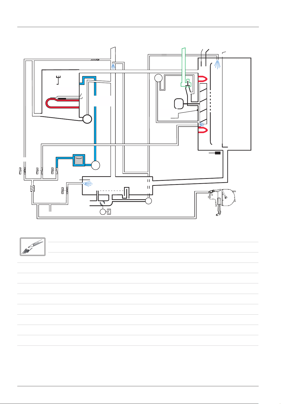
Basic principle SCC_WE
B1
Solenoid filling
Y1
S11
Steam element
Steam generator
Solenoid
moistening
Y3
Solenoid
quenching
Water supply
S2
Level
electrode
Thermocouple
steam generator
Self Clean (SC) pump
Solenoid
Care
Y4
Y2
Check valve
B5
F3
Care
B2
Drain
Safety
thermostat
steam generator
M4
M12
Care pump
Thermocouple
quenching
Venting pipe
S12
M7
Emergency drain
Drain valve
Differential pressure
sensor
P1
Clima valve
Fan motor
Thermocouple humidity
B4
Quenching box
M6
Thermocouple cabinet
Y5
M1
Hot air
element
Door contact switch
Safety thermostat cabinet
F4
Core probe
Air baffle
S3
Hand shower roll guide
B3.1 - 3.6
Cabinet
V02 en, SCC_WE - 4 -
Page 5
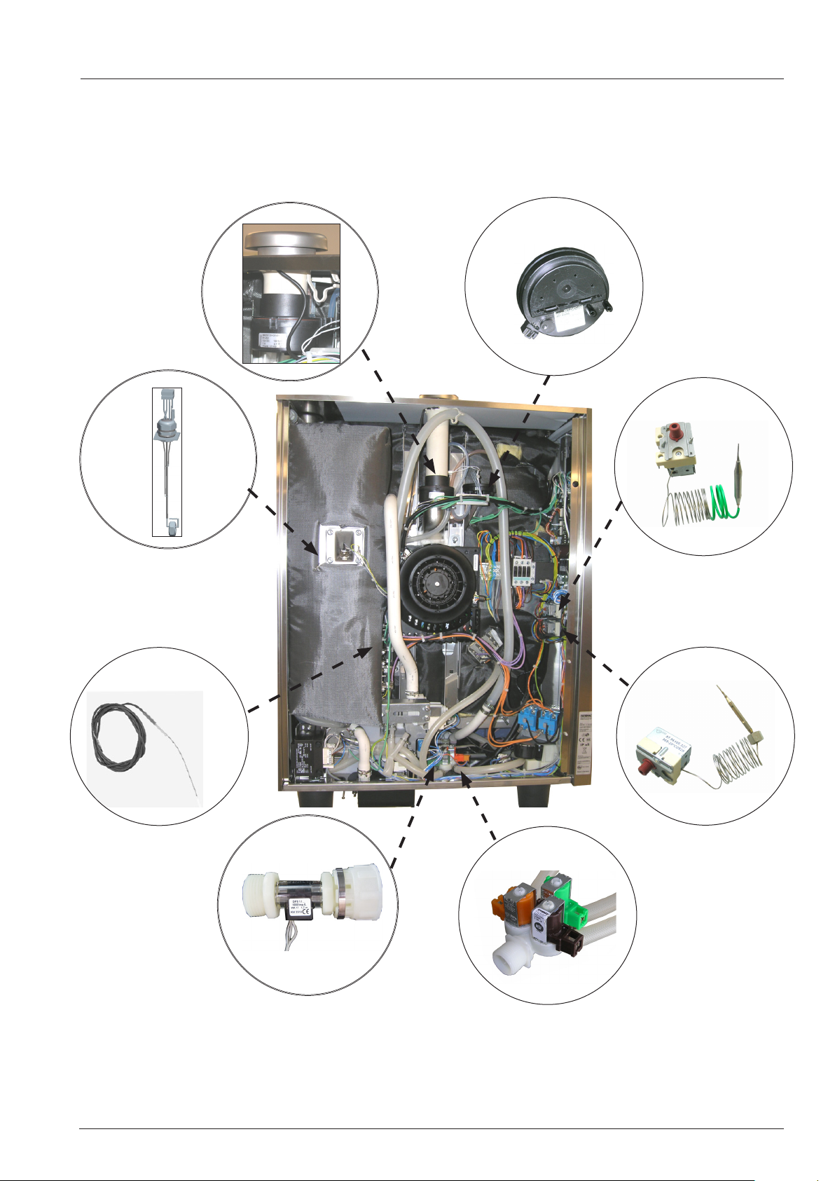
Parts location
Solenoid humidity (Y5)
Differential pressure sensor (P1)
safety thermostat
steam generator
(F3)
level electrode S2
Thermocouple steam
generator (B5)
safety thermostat
cabinet (F4)
CDS (S11)
triple solenoid
Y1 lling - Green
Y3 moistening - Brown
Y4 Care valve - Orange
- 5 - V02 en, SCC_WE
Page 6
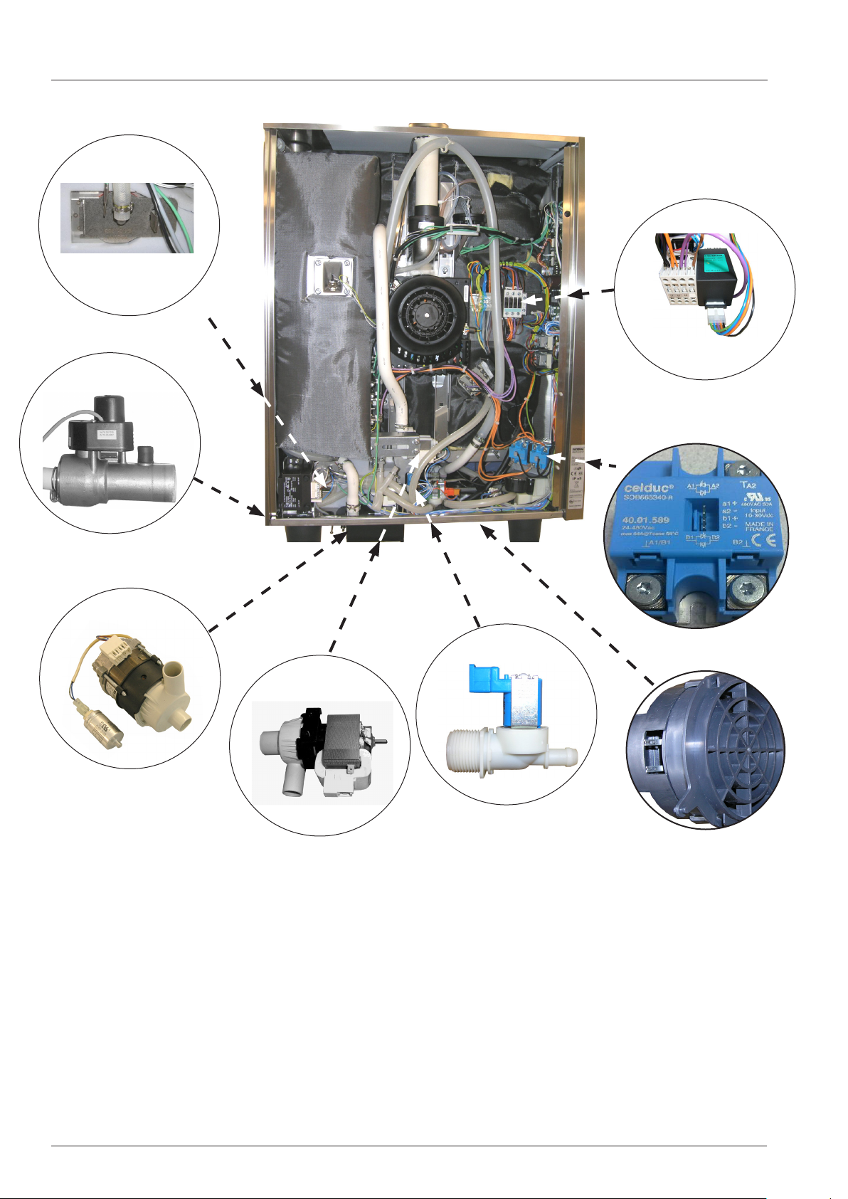
Parts location
Quenching nozzle and
Thermocouple B2
Drain valve
(M7 and S12)
Main contactor (K1)
Noise lter (Z1)
SSR (V1-)
CleanJet Pump
(M6)
SC Pump
(M4)
Solenoid Y2
quenching
Loud speaker T2
V02 en, SCC_WE - 6 -
Page 7
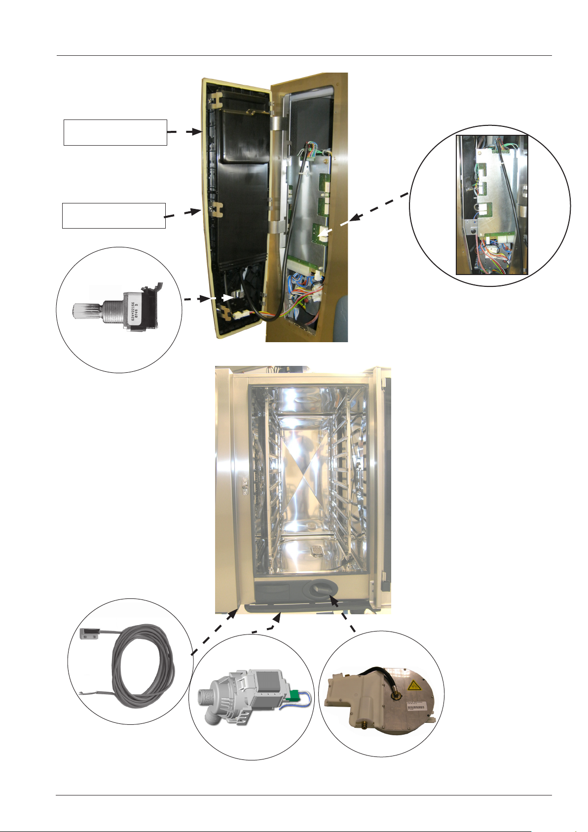
Parts location
Interface PCB (A1)
TFT Display
Puls generator
(S6)
CPU (A2)
Door contact
switch (S3)
Care Pump
(M12)
- 7 - V02 en, SCC_WE
Hand shower roll
guide
Page 8
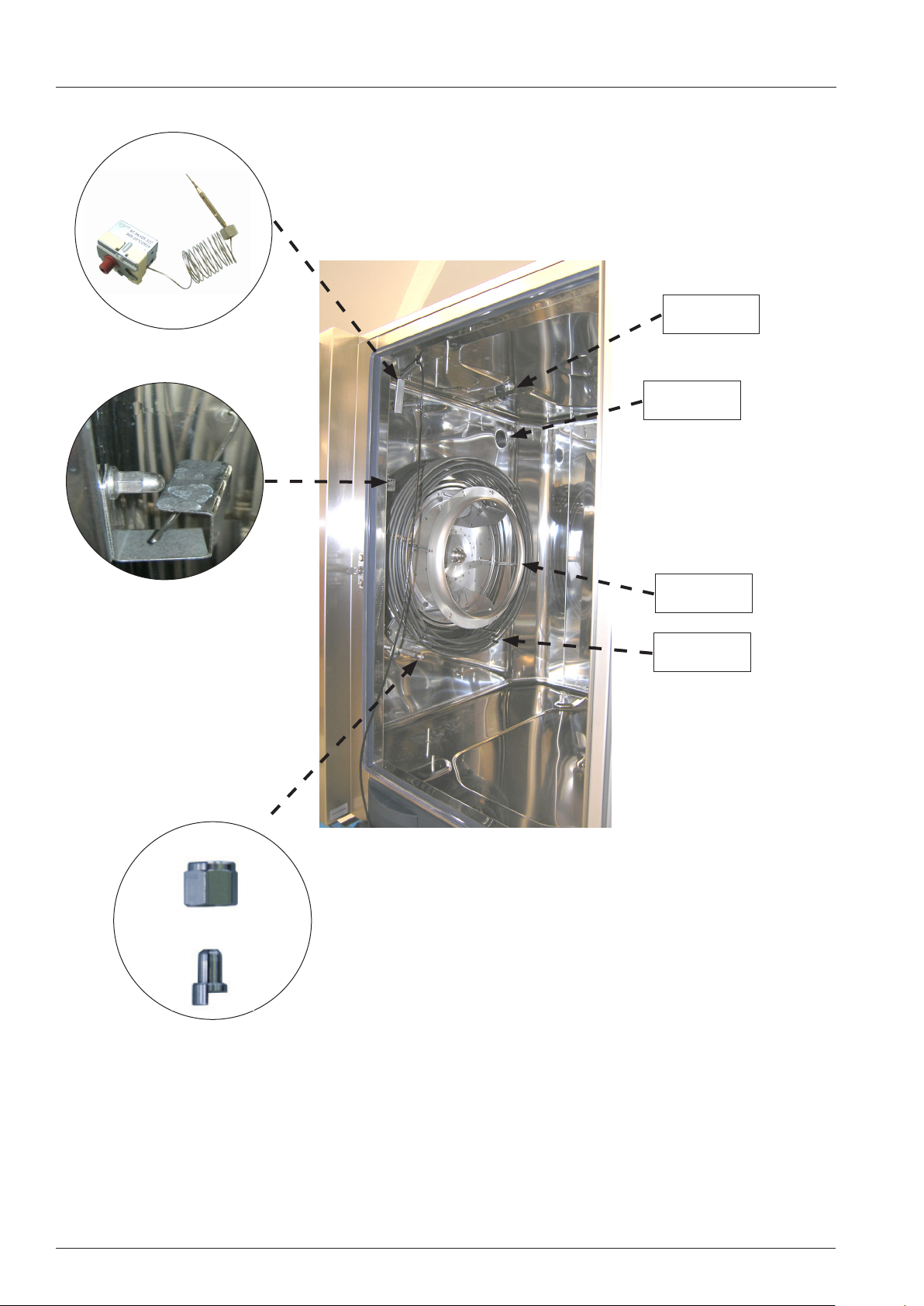
Parts location
Safety thermostat
cabinet (F4)
Cabinet sensor B1
CleanJet
nozzle
Steam inlet
Union nut
Moistening nozzle
Fan wheel
Hot air hea-
ting element
V02 en, SCC_WE - 8 -
Page 9

Changes of the unit
Differences from SCC_WE (Index H) compared with SCC Index G
1. Unit self test after installation; all components are tested for correct function and determination of
boiling point;
2. Steam mode preset to boiling point (no hot air supply), 30-130°C possible (86 - 266°F)
3. New humidity control (Clima valve) for advanced dehumidification
4. New fan motor rotates left - right
5. New PCB and TFT touch display with Ethernet connection
6. Moistening nozzle integrated into hot air heating element flange of electric units
7. Modified cover for quenching box
8. Cooling fan is temperature controlled
9. Cleaning program „Light“ is split into „Light Quick“ duration approximately 1h 05min and
„Light standard“, duration approximately 1h 46min.
10. Operator and Application manuals are available on display;
- 9 - V02 en, SCC_WE
Page 10
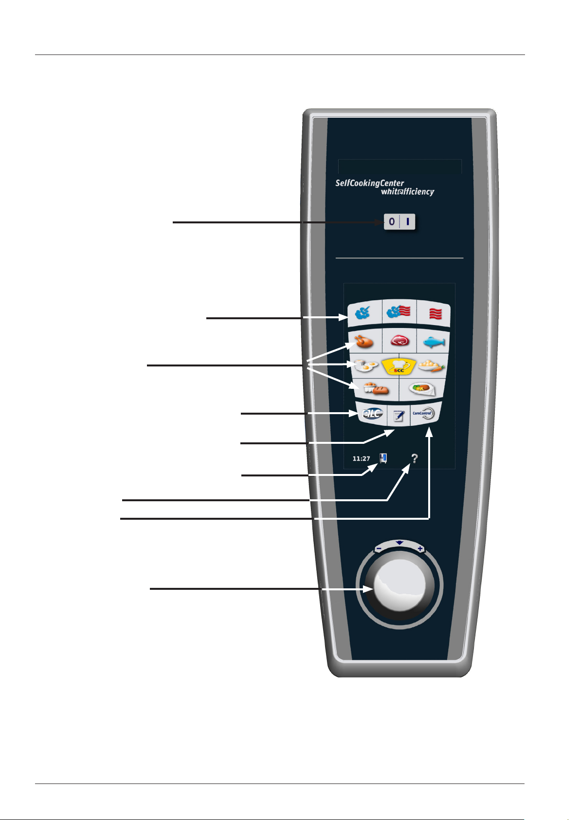
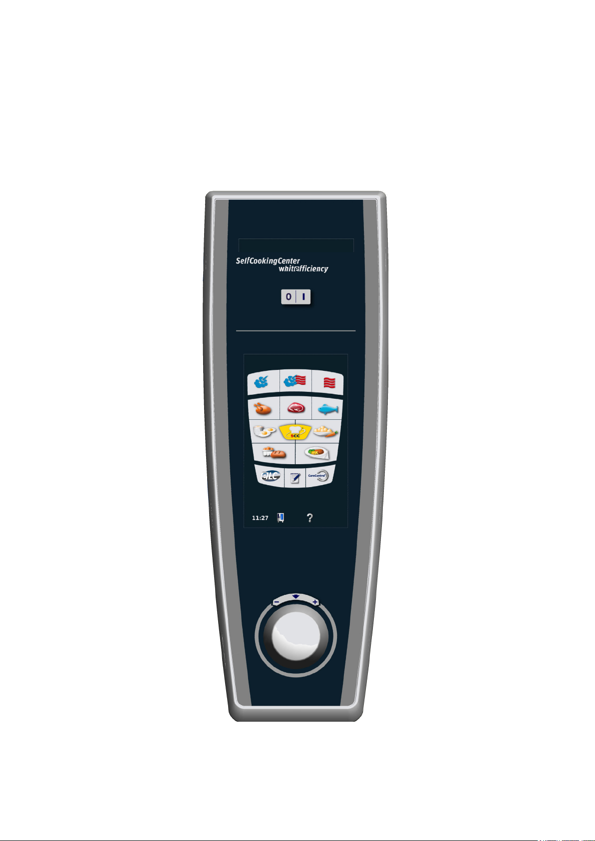
Operator panel SCC_WE
ON/OFF switch
Manual Modes
SCC-Processes
ELC-Key: Activation Efficient Level Control
Program Key: Activation Programming mode
Function Key: Activation personal settings & Service
Help Key
Care Key
Central Dial
V02 en, SCC_WE - 10 -
Page 11
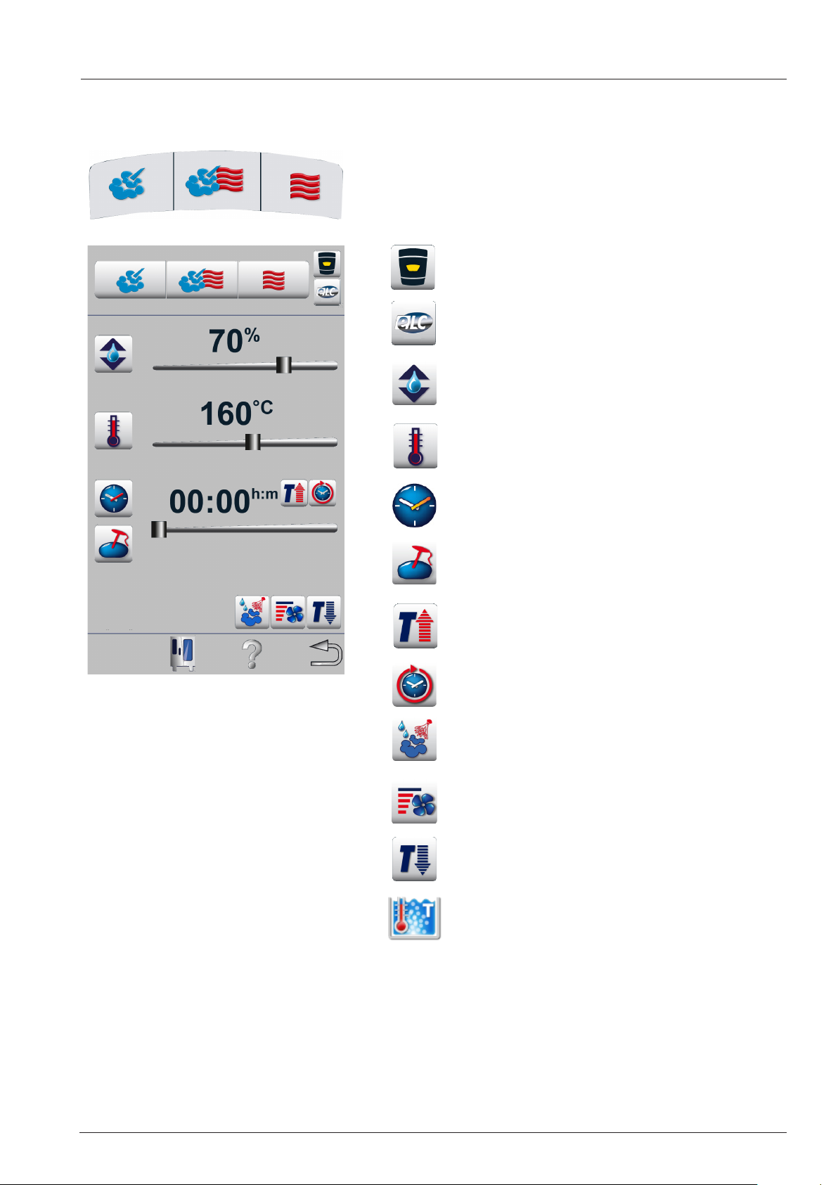
Operator panel SCC_WE: Manual Modes
Home - back to general display
Efficient Level Control
Humidity setting
Temperature setting
Time setting
Core probe setting
Pre heating
Time: continuous
Moistening
Fan wheel speed setting
Cool Down
Steaming at boiling point (no hot air)
- 11 - V02 en, SCC_WE
Page 12
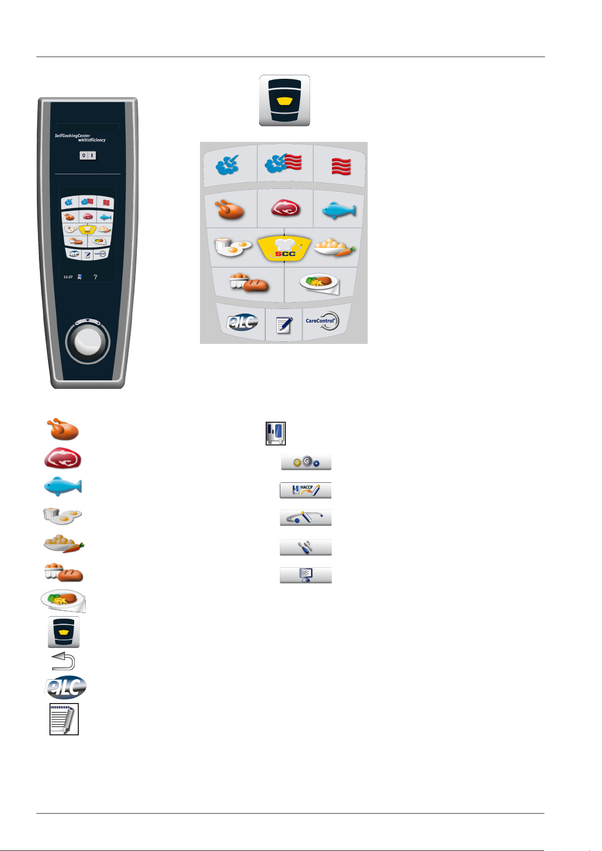
Survey Pictogram
Poultry
Large roast
Fish
Egg dishes / Desserts
Side dishes
Bakery products
Finishing
Home - back to general display
Back to previous level
Efficient Level Control
Function key
Settings
HACCP download
Communication (pictures, USB, IP, Sound)
Service
Display configurator
Record Modus (calibrated products)
Store
V02 en, SCC_WE - 12 -
Page 13
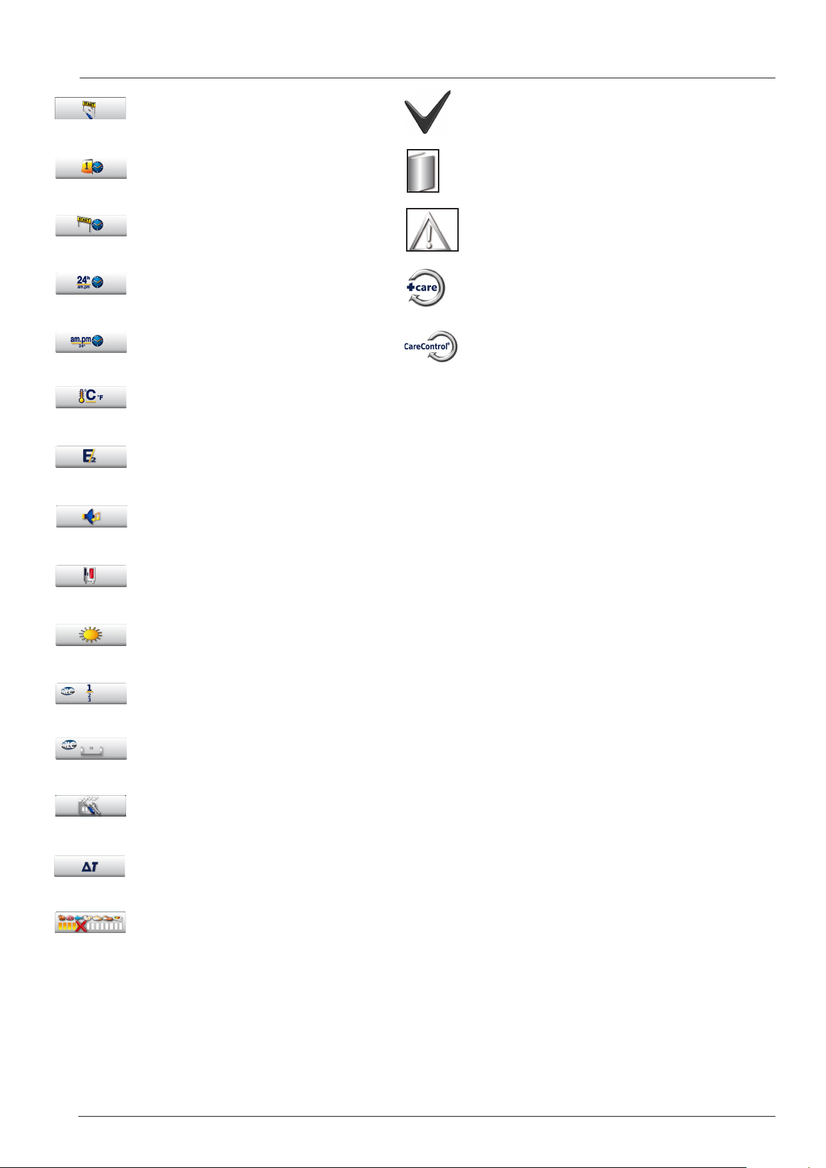
Survey Pictogram
Start Service Level
Date and time
Start time
Time format 24h
Time format am / pm
Temperature setting °C - °F
Half energy
Confirm
Operator and Application Manual
Safety advice
CleanJet +Care
Care Control
Setting ring tones
Show Mode (when in red)
Display brightness
Sequence of levels
Number of levels
Factory settings - english, °C, 24 hours etc
Delta T
Prozess abort key
- 13 - V02 en, SCC_WE
Page 14
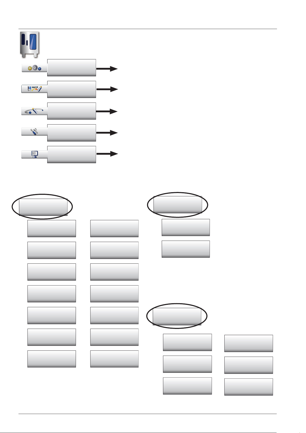
Function Key - Settings - Service - Communication
Function Key
Settings
Settings
HACCP
Communication
Service
Display Configurator
Record modus
Time, Language, °C/°F, Acoustics, Plate weight etc.
Download HACCP Data
Pictures, Ring tones, USB Stick, IP Address
Unit Data, Service package, Hotline numbers, Descaling,
Show Mode
Communication
Date, Time
Start time
Language
°C - °F
Brightness
Number of levels
Plate weight
Bankett
h:m m:s
24h am:pm
Delta T
E/2
Ringing tones
Sequence
of levels
Plate weight
à la carte
USB Stick
Network
Service
Unit Data
Diagnostic
Hotline
Empty Steam
generator
Descaling
(>16%)
Show Mode
V02 en, SCC_WE - 14 -
Page 15

- 15 - V02 en, SCC_WE
Page 16
V
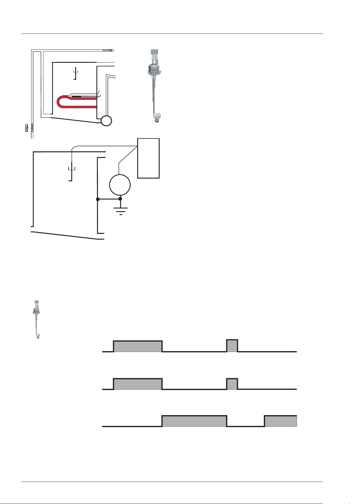
Water level control steam generator SCC_WE
Center level electrode S2 => Ground: 2 - 6V AC:
S2
B5
F3
water level too low
steam heating must switch OFF
solenoid valve filling Y1 ON
M4
Y1
Center level electrode S2 => Ground: 0V AC:
water level reached
steam heating can switch ON
PCB
S2
AC
solenoid valve filling Y1 switched OFF
Level electrode can be measured at X12: 1-4
The level electrode is equipped with two side electrodes to ensure safe water level recognition even
when the center level electrode is scaled. These
side electrodes compensate for the build up of scale.
Permanent water level control;
Maximum continuous steam time: 2 Minutes,
Property of connected water:
Conductivity must be above 50µS/cm;
St.Gen. empty: ca. 2 - 6V AC
St.Gen. full: 0V
SV Filling on 230V
SV Filling off 0V
Heating on 230V
Heating off 0V
Filling SG Max. heating 2 Min. Control Steam heating
V02 en, SCC_WE - 16 -
Page 17
SC (Self Clean) Automatic
During the production of steam, the concentration of minerals inside the steam generator will
increase over time. These minerals settle on the heating elements and heat exchanger as
well as the interior steam generator walls.
In order to reduce this effect the steam generator will be pumped off and ushed regularly depending
on the duration of steam production. This process needs approximately 45 seconds.
After emptying the steam generator it will be lled automatically with fresh water.
There are 4 conditions to start this SC Automatic:
1. Heating time of the steam generator must exceed 60 min.* and
2. the temperature of the thermocouple steam generator must be below 65°C (149°F) and
3. the temperature of the thermocouple interior cabinet must be below 70°C (158°F) and
4. the unit is switched ON.
In case the unit is used permanently the above mentioned temperature conditions
can not be met.
In this case the „forced SC Automatic“ applies as follows:
1. The heating time of the steam generator reaches twice the set duration*, e.g. 120 min. and
2. the unit door is open for longer than 30 seconds
* The marked values can be changed in unit specific ranges using the diagnostic program.
After completion of the SC-Automatic the accumulated steam heating time is re-set to zero.
SC-Automatic does not replace the need for descaling and/or installing water treatment filter
- 17 - V02 en, SCC_WE
Page 18
SCC_WE Electric (Index H): Basic principle
B1
B3.1 - 3.6
F4
P1
M4
M6
Y1
Y2
Y3
B2
M1
S2
M7
S12
B4
B5
F3
S3
Y4
S11
M12
Care
Y5
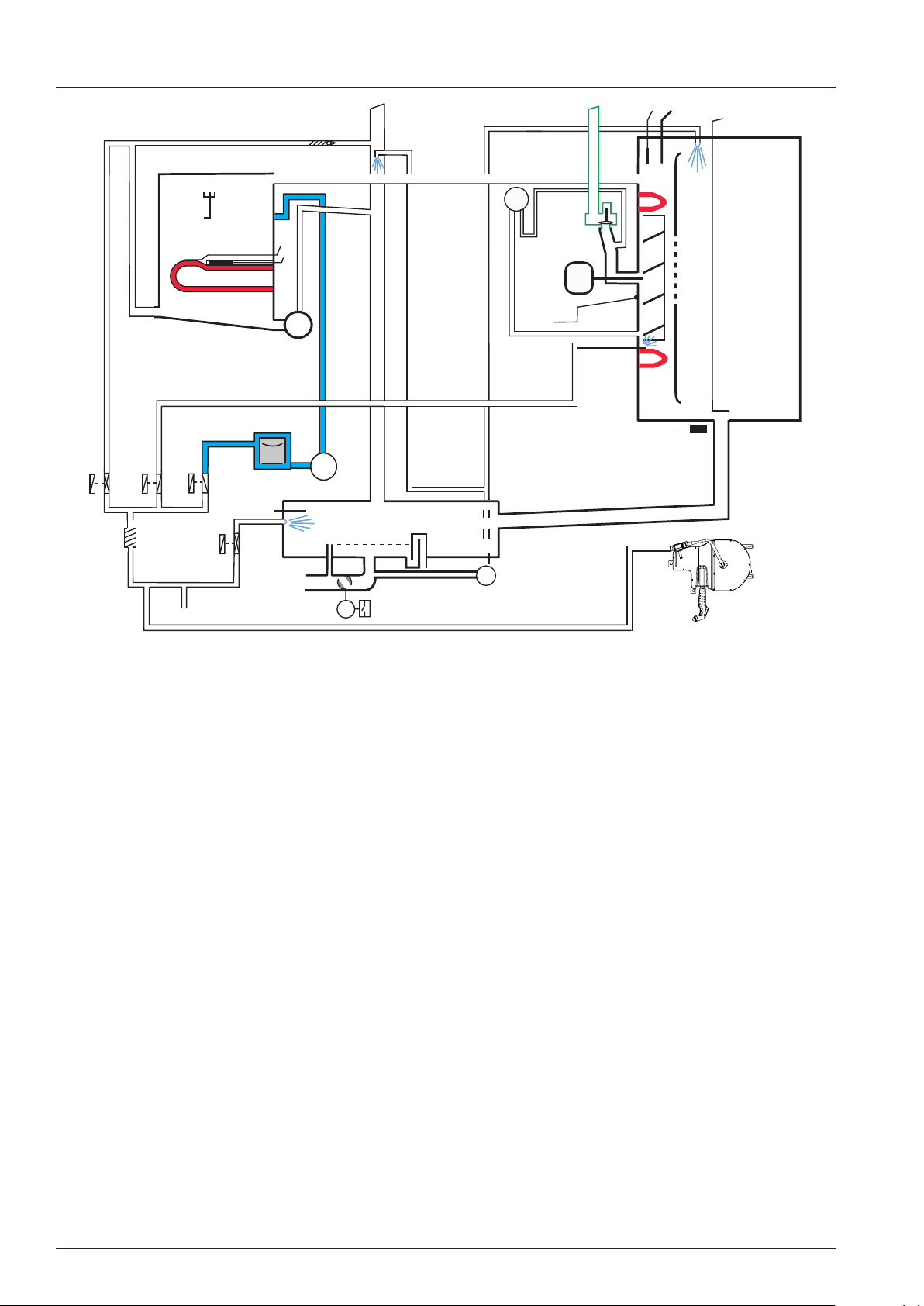
B1 Thermocouple interior cabinet
B2 Thermocouple quenching
B3.1-B3.6 Thermocouples core temperature
B4 Thermocouple humidity
B5 Thermocouple steam generator (preheat, 180°C (356°F) max)
F3 Safety thermostat steam generator 160°C (320°F)
F4 Safety thermostat interior cabinet 360°C (680°F)
M1 Fan motor (Floor unit: top)
M4 SC-pump
M6 CleanJet pump
M7 Motor drain valve / ball valve
M12 Care pump
S2 Level electrode
S3 Door reed switch
S11 CDS sensor
S12 Micro switch drain valve
P1 Differential Pressure sensor humidity
Y1 Solenoid valve filling
Y2 Solenoid valve quenching
Y3 Solenoid valve moistening
Y4 Solenoid valve Care
Y5 Solenoid valve Clima
SCC 201/202 only:
M2 Fan motor bottom with jumper ( Floor units only)
V02 en, SCC_WE - 18 -
Page 19
Manual modes SCC_WE / Boiling point recognition
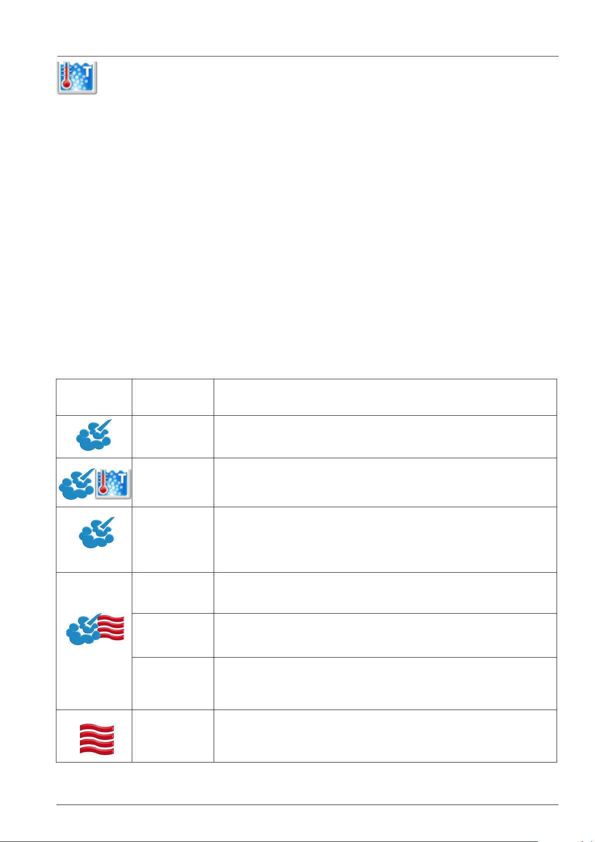
Steam mode in relation to boiling point recognition
During self test (after initial installation) the unit will determine the installation altitude by water boiling
point recognition.
As the boiling temperature declines with increasing altitude above sea level, the water boiling point
determines the installation altitude.
During self test the steam production will be active until the quenching sensor B2 reaches 70°C
(158°F). At this time the pcb will memorise the temperature measured by the interior cabinet sensor B1
as the boiling point temperature at the actual point of installation.
To run a manual cooking mode the following steps must be taken:
1. Cooking mode is selected.
2. Time or core temperature is selected.
3. Cabinet door is closed (door contact).
4. Fan motor is running (speed signal via bus).
5. In wet modes (Steam, Combination) the steam generator must be filled with water (level electrode)
6. In wet modes (Steam, Combination) the steam generator will be preheated
(thermocouple steam generator)
Mode
Temperature
range
30° (87°) up to
boiling point
at boiling point
above boiling
point up to
130°(266°)
30° (87°) up to
boiling point
above boiling
point up to
300°(572°)
30 - 300°C
(86 - 572°F)
Responsible sensor
Cabinet sensor B1 controls steam heating
- Humidity setting not possible
Cabinet sensor B1 controls steam heating
- Humidity setting not possible
Humidity control (P1, M1 rpm and B4) controls steam heating,
Cabinet sensor B1 controls Hot air heating at 50%, (only
possible when humidity is above 70%)
- Humidity setting not possible
Cabinet sensor B1 controls Hot air heating up to set temp.;
Cabinet sensor B1 controls steam heating
Cabinet sensor B1 controls Hot air heating up to set temp.;
Humidity control (P1, M1 rpm and B4) controls steam heating,
Alternating supply of steam and hot air depending on the reached
temperature and humidity.
- Humidity setting is possible
30 - 300°C
(86 - 572°F)
Cabinet sensor B1 controls Hot air heating
- Humidity setting is possible (humidity from food only)
Quenching controlled by B2 at 80°C (176°F) Wet, 90°C (194°F) in Hot Air
- 19 - V02 en, SCC_WE
Page 20
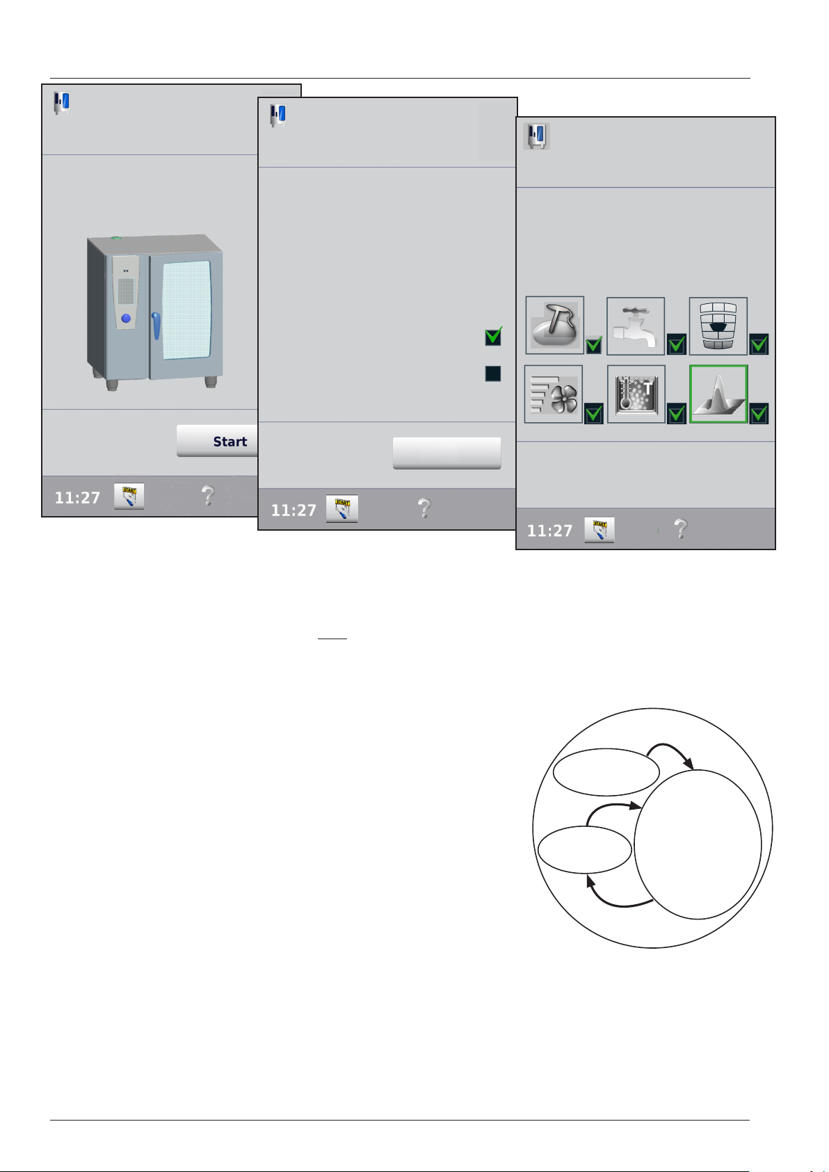
Selftest
Selfttest
Your SCC will carry out an automatic
self test and adjust itself perfectly to
the set-up conditions and the altitude.
Next
Selfttest
Your SCC will carry out an automatic
self test and adjust itself perfectly to
the set-up conditions and the altitude.
To determine the optimum number of
cleaner and rinse aid tablets, please specify
whether the unit is connected to normal
water or soft water. Please press the appropriate button
Unit is connected to soft water
(up to 8,75° e)
Unit is connected to normal water
(over 8,75° e)
Selfttest
Your SCC will carry out an automatic
self test and adjust itself perfectly to
the set-up conditions and the altitude.
Softwater:
7°dH, 12,5°F, 8,7°E, 125ppm, 1,25 mmol/l
Self test
Note: Gas units: In case the unit was NOT delivered with the correct gas type configuration, it must be converted prior of starting the self test. Please refer to gas manual!
SCC_WE and CM_P units will run a automatic Self Test routine after installation.
This Self test will start under the condition, that the tempearture of B1,
B2 and B4 are below 40°C (104°F).
Additionally 1 at and closed GN container (max 20mm) shall be inserted into the cabinet with the opening facing down at a height center to
Component test
the fan wheel. (201 - 202: 2 fan wheels = 2x GN containers)
The self test comprises a component test, calibration and determination of the boiling point
After the component test (S2, M4, Y1-Y4, CDS) the calibration will start
Boiling point
calculation
with the offset setting on P1 before the unit will determine the pressure
values for all fan speeds and directions in cold and dry condiition.
During step 200 the boiling point will be determined and stored.
This is followed by P1 calculating the pressure values for all fan speeds and
directions in steam and later combination mode 170°C (338°F).
Should at a later point in time the unit be reinstalled at a altitude more than 300m different to the original installation height, a new self test should be initialized in order to determine the new boiling point.
Such re-initialization can be be done in Basic settings, self test.
Selftest
Calibration
step 200
Calibration:
During a manual calibration only the P1 pressure values for cold (<40°C), steam (at boiling point) and combination (170°C) are calculated.
There will be NO determination of a new boiling point.
V02 en, SCC_WE - 20 -
Page 21
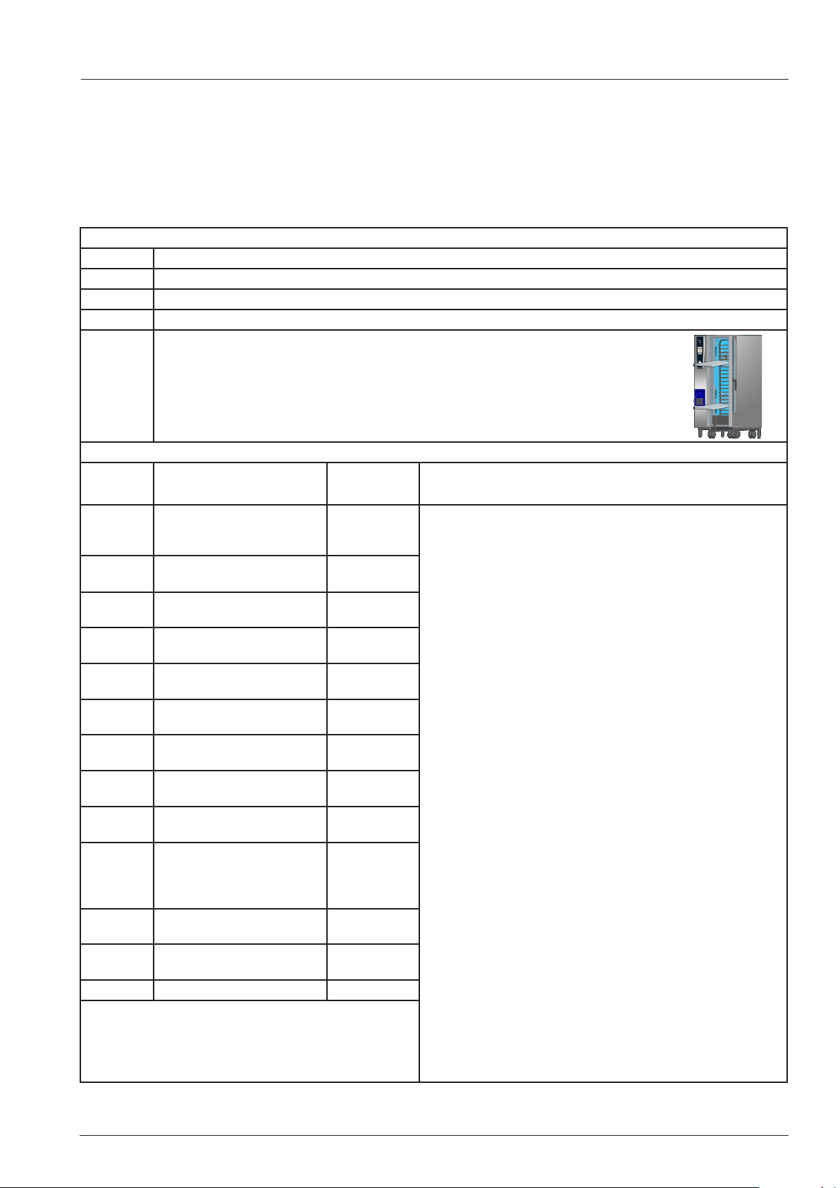
Selftest
During the self test the individual component groups are indicated ticked off one by one.
IIn case an error number is displayed switch the unit OFF and ON again to access Service level.
If the door contact, thermocouple interior cabinet, bus cable to motor or ignition box is defective, the selftest will
be interupted
Note: During Self Test it is always possible to access the Service diagnostic mode!
Pre condition before Self test and Calibration
temperature of cooking cabinet sensor B1 is below 40°C (102°F)
temperature of quenching sensor B2 is below 40°C (102°F)
temperature of humidity sensor B4 is below 40°C (102°F)
door contact closed
heating: OFF
fan motor: OFF
left side panel closed, interior cabinet clean, if possible dry;
to achieve best calibration values insert a closed 20mm GN container
with opening facing down onto the rail closest to the center of the fan wheel
(201-202: 2 motors - 2x GN container)
Step Function possible error
message
0 ready fo calibration Any indicated error relates to the corresponding malibration
10 checking calibration
conditions
20 Measuring Offset P1 with
fan motor not turning
100 - 115 pressure measurement cold
table unit 61 - 102
100 - 131 pressure measurement cold
floor unit 201 - 202
200 steam heating up to boiling
point without fan motor
202 steam heating with fan
motor
210 - 225 pressure measurement
steam table unit 61 - 102
210 - 241 pressure measurement
steamfloor unit 201 - 202
300 heating of cabinet to
193°C (380°F)
followed by 60 sec. to 170°C
(338°F) steady condition
301 - 316 pressure measurement
combi table unit 61 - 102
301 - 332 pressure measurement
combi floor unit 201 - 202
999 calibration sucessfull
10
200
e.g. 302
reason for error - remedy
step.
e.g. error 10 will be indicated, when the condition for calibrations is not given.
Reason: B1, B2 or B4 is above 40°C (104°F)
16 steps for each fan motor, (32 steps with floor models), e.g.
100: running fan motor at constant speed „1“
101: store P1 value at this given speed
e.g. error 200 is indicated, when the steam heating will not
reach the necessary 70°C (158°F) to detremine the boiling
point in the allocated time.
Reason: e.g. SSR (energy optimising) or gas burner is not
activated etc.
e.g. error 302 is indicated, if sensor P1 does not give any or
any valid value at this time.
Reason: P1 defective or hoses to P1 blocked by water.
These errors are indicated during the respective calibration
step is running.
After solving the problem the Selftest must be started again.
- 21 - V02 en, SCC_WE
Page 22
Humidity control SCC_WE
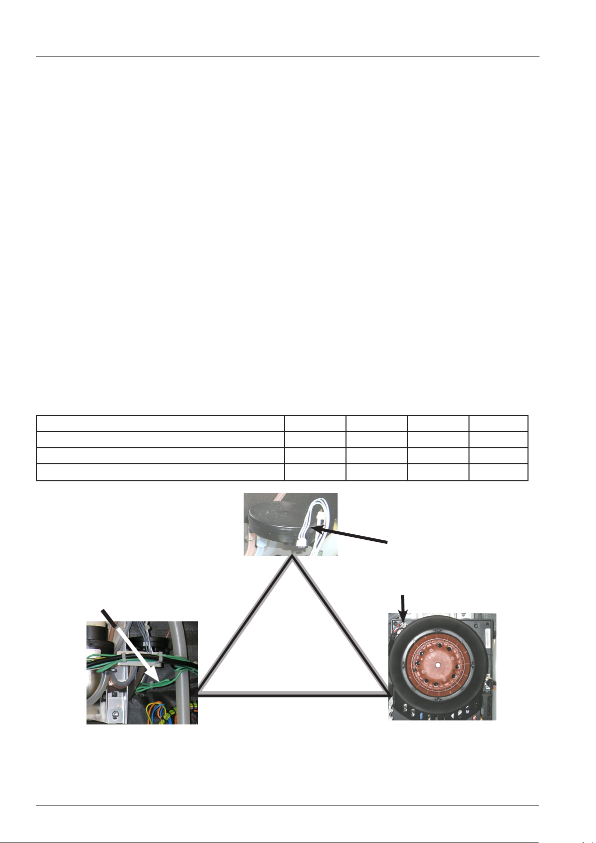
In order to measure the humidity inside the interior cabinet the following pysical principle is used:
When the fan wheel is turning, the rear fins create a differential pressure on pressure sensor p1 via the
connecting hoses (inner and outer connection).
The pressure sensor P1 is supplied with 12V DC. When the fan wheel is at a stand still, the offset voltage is between 0,45 - 0,55V DC.
The differential pressure is dependent on:
1. The speed of the fan wheel
2. The temperature in the cabinet
3. The amount of humidity in the cabinet
The following rules apply:
The output voltage of P1 is higher when the fan wheel turns faster.
The output voltage of P1 is higher when the cabinet temperature is lower.
The output voltage of P1 is higher when the humidity in the cabinet is lower.
This differential pressure is converted into a dc voltage for processing by the pcb.
Sample: SCC_WE 101E
NOTE: The given values are only average values and shall only demonstrate the relationship of pressure values P1 to change in speed, temperature and humidity.
500 rpm 1000 rpm 1450 rpm 1550 rpm
Cold and dry 1,1V 2,2V 2,9V 3,1V
Warm and humid - Steam 100°C (212°F) 0,7V 1,7V 2,0V 2,2V
Hot and humid - Combination 180°C ( 0,6V 1,5V 1,7V 1,9V
Differential pressure sensor P1
Thermocouple B4
Humidity
Humidity control
Bus signal
Motor rpm
V02 en, SCC_WE - 22 -
Page 23
Humidity control SCC_WE
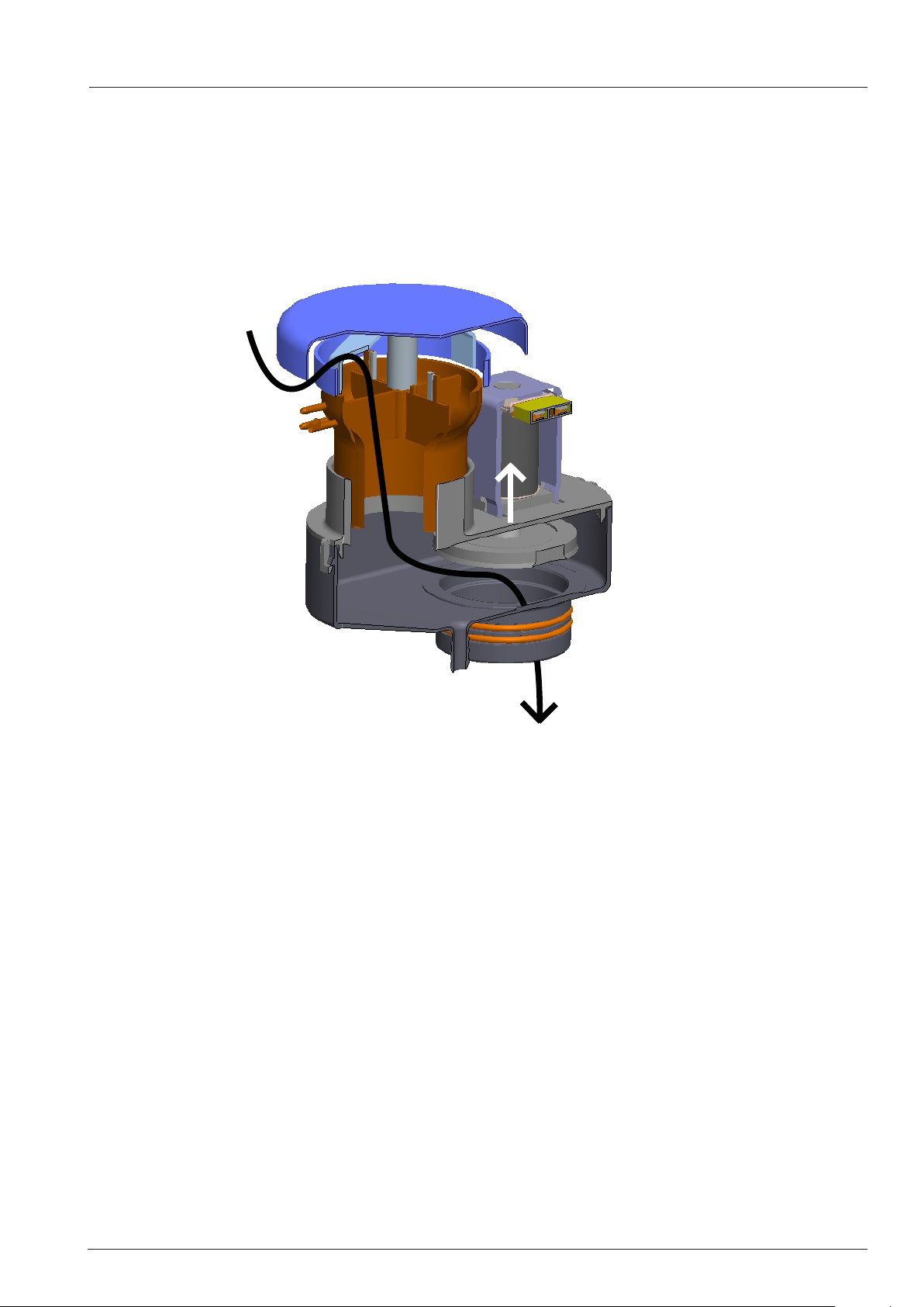
If the measured humidity value is too high, the clima valve Y5 will be activated and the closing disk will
be lifted. The negative pressure behind the fan wheel will cause dry air from the kitchen be sucked into
the cabinet. The humid air will be displaced and pushed through the cabinet drain into the quenching
chamber.
This Clima valve also functions as the safety relief valve.
Cross section of the clima valve:
Y5
Emergency humidity control:
In case the differential pressure sensor P1 is defective (no signal), the steam generator will be activated by time control automatically to a humidity level of 60%.
At the same time error „Service 36“ will be shown.
Should the signal of P1 be out of the standard range (invalid signal), humidity will be controlled by the
quenching sensor.
At the same time error „Service 37“ will be shown.
- 23 - V02 en, SCC_WE
Page 24
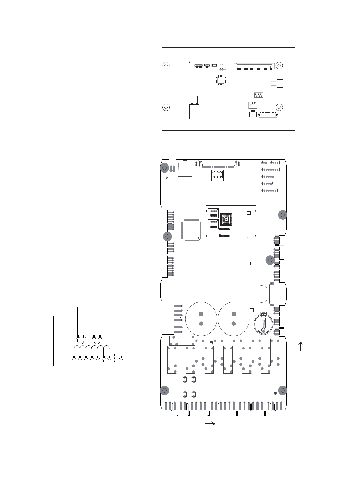
SCC_WE CPU
X150
X152
X151
X155
X153
X158
X154X102
X7
X10
K8
X18
K2
K1
K5
X19
X75
K4
K3
K10
K9
X15
X27
X26
G3
X29
X60
+
X23
X20
F1
F2
X21
K6
K7
K11
K12
X14
+
X13
X30
X12
X1
X16
X6
X4
X5
X2
X3
X51
X107
D15
X25
X11
X24
X106
X8
LED V10
LED V68
LED3
F2
2AT
F1
2AT
A1
A2
11,5V
*
T1
F1
2AT
250
?
230
240
220
18V
?
208
?
200
F2
5AT
N
0
1
pin counting 1
V02 en, SCC_WE - 24 -
Page 25

SCC_WE CPU - Terminal connection - LED Code
Interface PCB A1
X7 Power input to ON/OFF switch
X10 Central dial
X102 Touch
X150
X151
X152
X153 Data cable CPU (X107)
X154 Data cable TFT
X155
X158
Main PCB A2
X1 Pressure sensor P1 - 12V DC
X2 Thermocouple B3.1 - 3.6 core probe
X3 Thermocouple B1 cabinet
X4 Thermocouple B2 quenching
X5 Thermocouple B4 humidity
X6 Thermocouple B5 steam generator
X8 Loud speaker T2 - 12V AC
X11 Solenoid Y5 Clima - 12V DC
X12 Level electrode S2 - 12V AC 600Hz
X13 Cabinet light - 11.5V AC
X14 Power supply from transformer T1: - 11.5V AC, 18V AC
X15 CDS Sensor - 12V DC
X16
X18 SC Pump M4, Cleanjet Pump M6
X19 Solenoid Y1, Y2, Y3
X20 Energy optimising (Sicotronic) - link on 2-4
X21 230V Power input
X23 UltraVent without Bus (USA only)
X24 SSR - 12V DC
X25 Drain valve M7, Micro switch S12 - 12V DC
X26
X27 Door contact S3 - 12V DC
X29
X30
X51 Bus cable
X54 USB connection
X60 SD card slot
X75 cooling fan M5, Care Pump M12, Solenoid valve Y4
X106 Ethernet connection
X107 Data cable Interface PCB (X153)
F1 2A slow 230V power input X21
F2 2A slow 230V power input X21
LED Code CPU:
LED V10: Internal power supply 3,3V processor ok
if V10 off and V68 ok - change PCB
LED V68: 18V power supply from T1 ok
if V68 off - check connection, change transformer T1
- 25 - V02 en, SCC_WE
Page 26
SD card - Changing PCB, new SD card
ONLY remove the SD card from the pcb, when the pcb must be replaced!
The SD card shall NOT be connected to any windows based reader or Computer! Doing so
will damage the data structure on the SD card and your unit will no longer function!
The SD card on port X60 contains all unit specific information like energy type, unit size etc.
The SD card is unit specific and shall NOT be transferred from one unit to another!
Service part pcb’s are sent without SD card. Should you need to replace an original pcb by
a service part pcb, remove the SD card from the old pcb and insert it into the new pcb. The
unit will not function if the SD card is not inserted.
This SD card is specially formatted and configured for use in the SCC_WE unit.
You can not replace it by a locally purchased SD card.
V02 en, SCC_WE - 26 -
Page 27
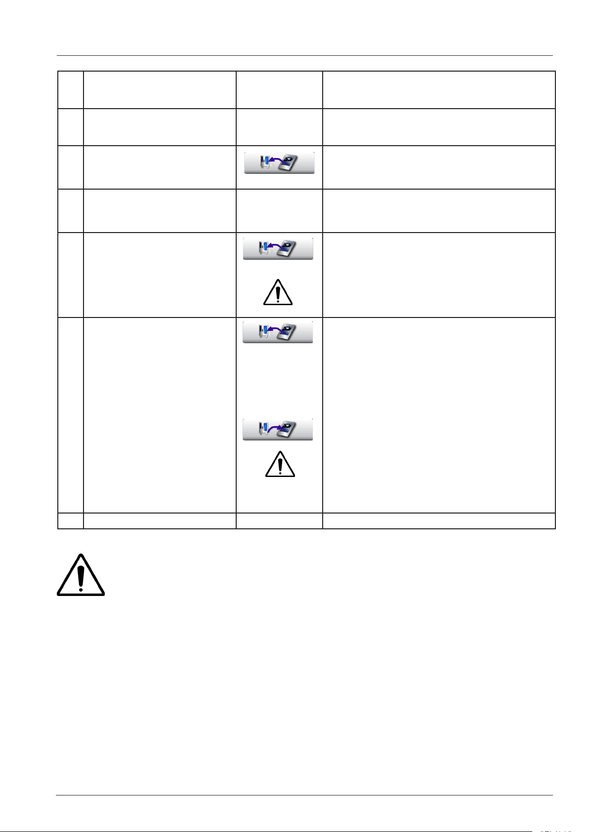
1 Software update Only possible when SD card is properly
inserted
2 PCB New - No SD card in-
serted
3 PCB new - Old SD card
(standard service call)
4 PCB old - New SD card
(Service 19.1)
5 PCB new - SD card from
other unit
(only in case of emergency,
e.g from unit from shown
room, when no SD card is
available as a service part)
6 a) SD card old - PCB from
other unit
(only in case of emergency,
e.g from unit from shown
room, when no PCB is
available as a service part)
Unit will not function
Upload icon key is shown, When pressing the
icon for 10 seconds, data are copied from SD
card to pcb
Data are copied automatically from pcb to SD
card.
Upload icon key is shown, When pressing
respective key for 10 seconds, data are copied
from SD card to pcb
Upload icon and download icon keys are
shown,
Display: Please select for recovery:
PCB was replaced (a)
b) PCB old - SD card from
other unit
(only in case of emergency,
e.g from unit from shown
SD card was replaced (b)
When pressing respective key for 10 seconds,
data are copied from pcb to SD card or vice
versa.
room, when no SD card is
available as a service part)
NOTE: Emergency only!
A SD card from another unit can ONLY be used, when this unit is of the same size and
energy (electric or gas)!
After using a new SD card (Case 5 and 6 (SD - card to unit) the Selftest must be re-activated in Basic Setting > Selftest.
- 27 - V02 en, SCC_WE
Page 28
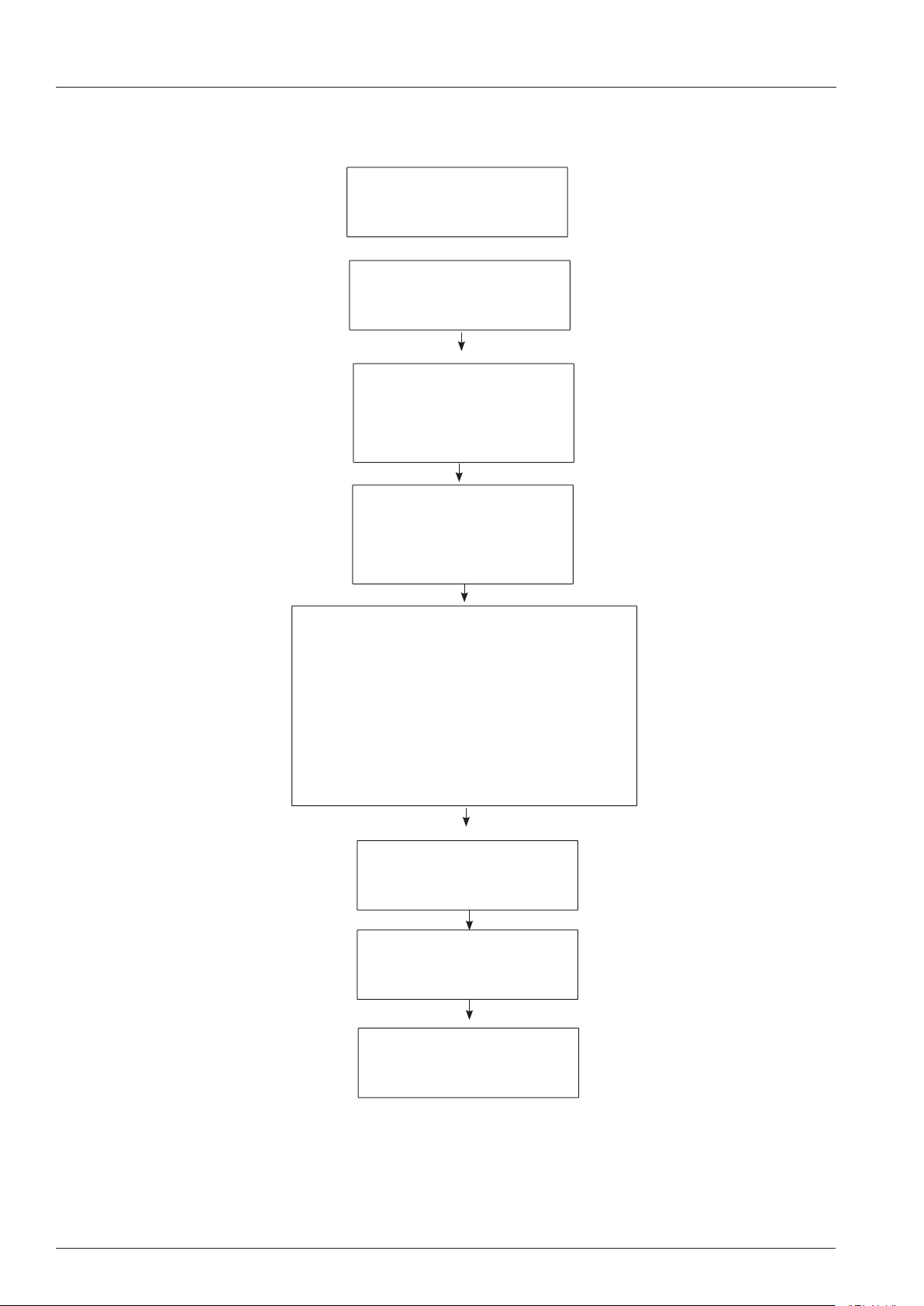
Fault tree Changing PCB SCC_WE
Isolate unit from power supply
(Disconnect control fuses F1, F2)
Removed SD card for usage in
Remove faulty PCB
Changing pcb
(pcb defective)
new PCB.
Replace pcb
Insert SD card from old PCB into new PCB;
In order to avoid Service 16 or 17 connect white USB
stick with latest software to USB interface before
re-inserting the control fuses.
(Software update is only possible when SD card is
properly inserted into PCB.)
Reconnect unit to power supply
(reconnect control fuses) and
switch unit ON
Software update to latest version
Only disconnect Software update
stick when basic SCC display is
shown.
V02 en, SCC_WE - 28 -
Page 29
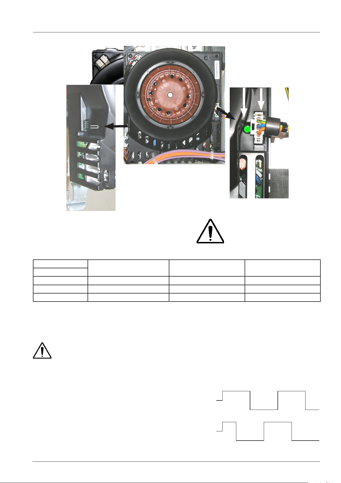
Fan motor SCC_WE Line
Bus
LED
100 - 240V
On floor units with 2 motors the bottom
motor carries a jumper for bus recognition. This jumper is part of the wiring
harness.
Only when the motor
is connected to mains
supply the green LED will
show and the bus signal
can be processed.
Voltage L1-L2-L3 Motor 40.03.378 - Rotor black
100 - 250V - 550W
3(N)AC 400V - 415V 61 -101 - 201 62 -102 - 202
3AC 200V - 240V 61 -101 - 201 62 -102 - 202
3AC 400V - 480V 61 - 202
Motor 40.03.513 - Rotor brown
200 - 250V - 700W
Motor 40.03.514 - Rotor brown
400 - 480V - 700W
NOTE: Gas units 62, 102 and 202 for countries with voltage 3AC200-240V, USA / Japan etc:
Gas units 62, 102 and 202 must be connected to L1 - L2, because the fan motor
40.03.513
is running on
200 - 250V only.
When changing the fan motor, a new motor shaft gasket must always be used!
There are 4 different fan speeds. It is possible that the motor will reduce speed independently to avoid
energy transfer by the rotating fan wheel.
The fan motor rotates clockwise - anticlockwise with a
120 sec 120 sec
120 second interval.
On floor units the bottom motor (with jumper) has a
60 second time lead in changing direction to the upper motor.
60 sec
120 sec
120 sec
Blink code LED: Please refer to error messages!
120 sec
- 29 - V02 en, SCC_WE
120 sec
Page 30
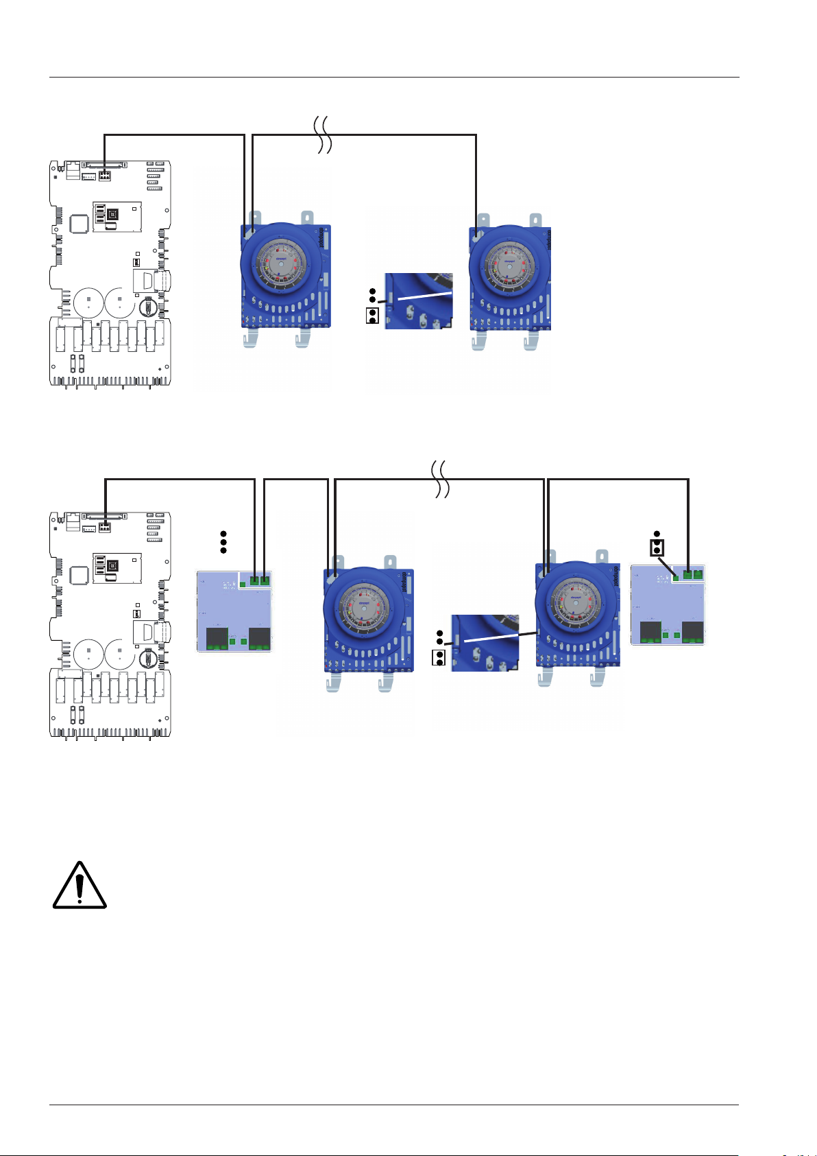
Bus connection
Electric units:
X51
61-102 E
201-202 E
D15
+
K12
K7
K6
K11
K8
F2
F1
Gas units
:
X51
D15
LED3
LED1
34
21
ON
LED2
+
G3
K9
K10
K2
K3
K5
K1
K4
Bottom motor
61-102 G
LED3
LED1
34
21
ON
201-202 G
LED2
+
+
K12
K7
K6
K11
K8
F2
F1
G3
K9
K10
K2
K3
K5
K1
K4
Bottom motor and bottom ignition box
The bus system is equipped with a 6-pol Mini-Fit plug system.
In the bus system the individual components have individual addresses. Each address only exists once
in a unit.
The duplicated components in a floor unit, Fan motor bottom and Ignition box bottom are
identified with a jumper on the component. This jumper is part of the control harnes.
The main pcb sends the action command via the bus cable.
Additionally the pcb receives information from the individual components via the same bus ( e.g. rpm).
The connecting sequence for the components on the bus is not important and can be chosen freely.
V02 en, SCC_WE - 30 -
Page 31
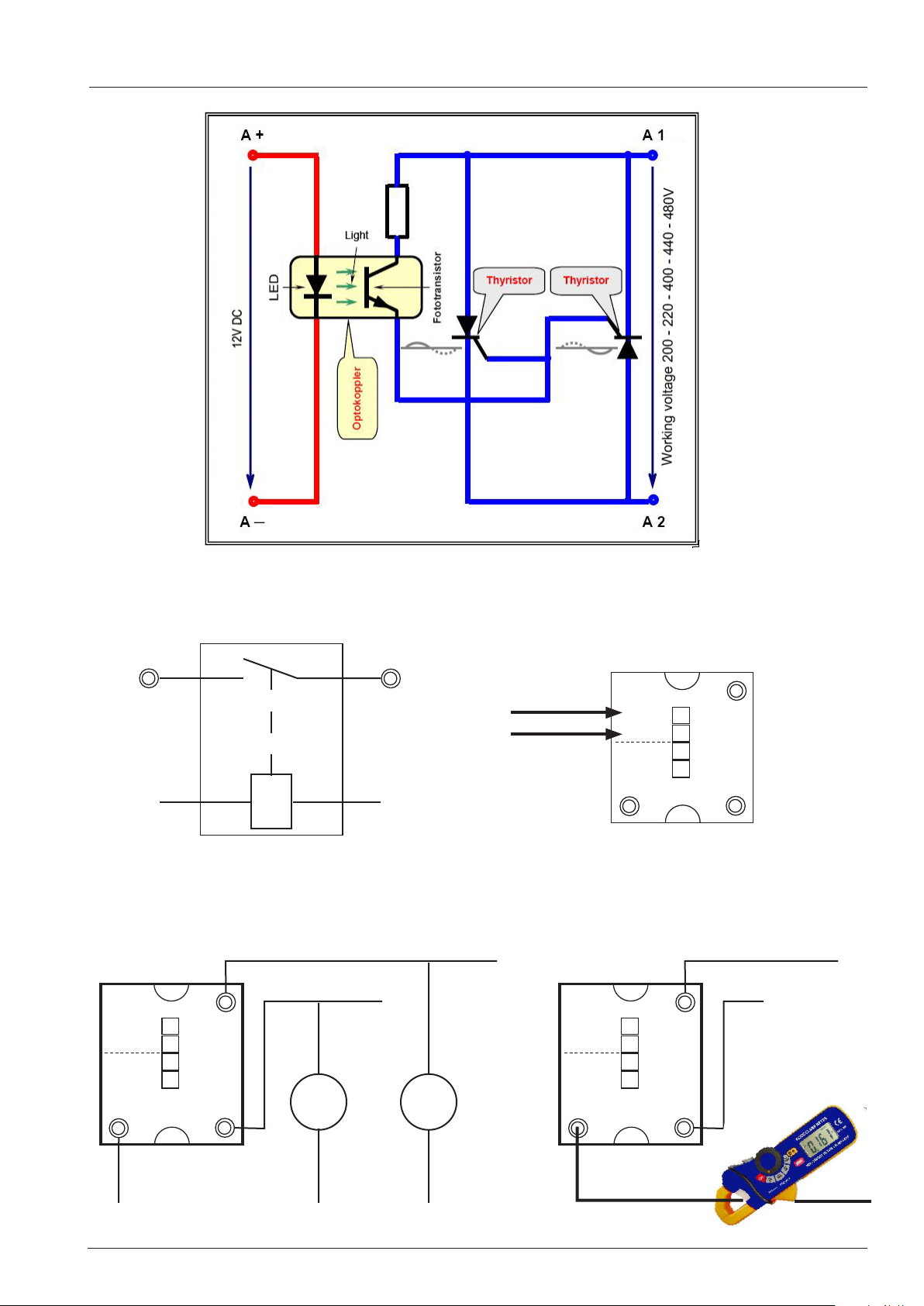
SolidStateRelay (SSR) internal design / Test
Contactor with 12V DC coil SSR with 12V DC control
A1/B1
12V DC
SSR Test: Unit is switched ON and cabinet door is open
L1 - L2 = 400V
+
-
+
-
A1/B1
B
A
B2
A2
A2
0V DC
Volt Volt
12V DC
0V DC
A1/B1
A1/B1 - A2 Steam / Dampf
A1/B1 - B2 Hot Air / Heißluft
+
-
+
-
A1/B1
+
-
+
-
A
B
A
B
A2
B2
A2
B2
0 Amp = ok
400V = ok 400V = ok
- 31 - V02 en, SCC_WE
Page 32
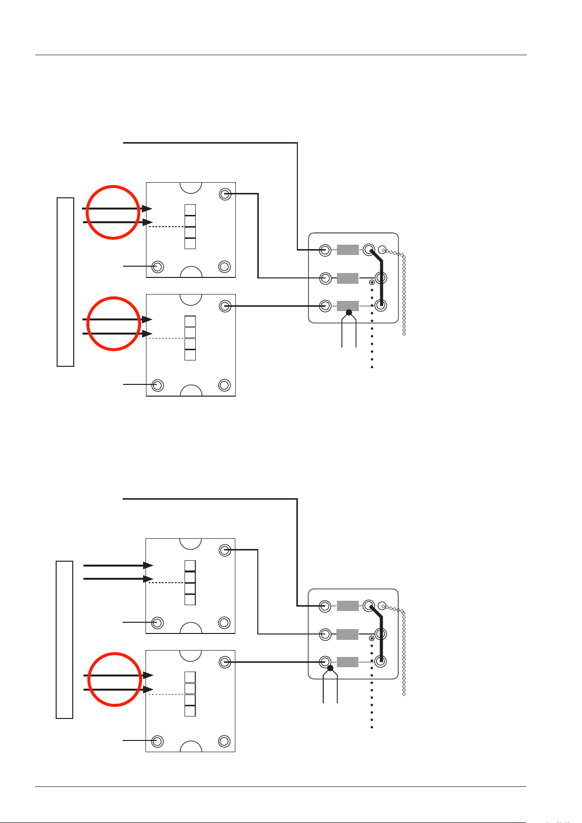
SSR 100% - 50% power at 3NAC/400V
Control of SSR steam element at 100% energy demand
Star connection 3(N)AC 400-480V
L3
Violet
A1/B1 - A2 Steam / Dampf
A1/B1 - B2 Hot Air / Heißluft
12V DC
0V DC
+
-
+
-
A1/B1
P
L2
A2
A
B
B2
Orange
C
B
12V DC
0V DC
Steam generator
safety thermostat 160°C
+
-
+
Thermocouple B5
-
A1/B1
A2
A
B
B2
Black
B5
L1
Control of SSR steam element at 50% energy demand
Star connection 3(N)AC 400-480V
L3
A1/B1 - A2 Steam / Dampf
A1/B1 - B2 Hot Air / Heißluft
0V DC
0V DC
P
L2
A1/B1
+
-
+
-
A
B
Violet
A2
B2
Orange
C
B
12V DC
0V DC
Steam generator
safety thermostat 160°C
+
-
+
-
Thermocouple B5
A1/B1
A2
A
B
B2
Black
B5
L1
V02 en, SCC_WE - 32 -
Page 33
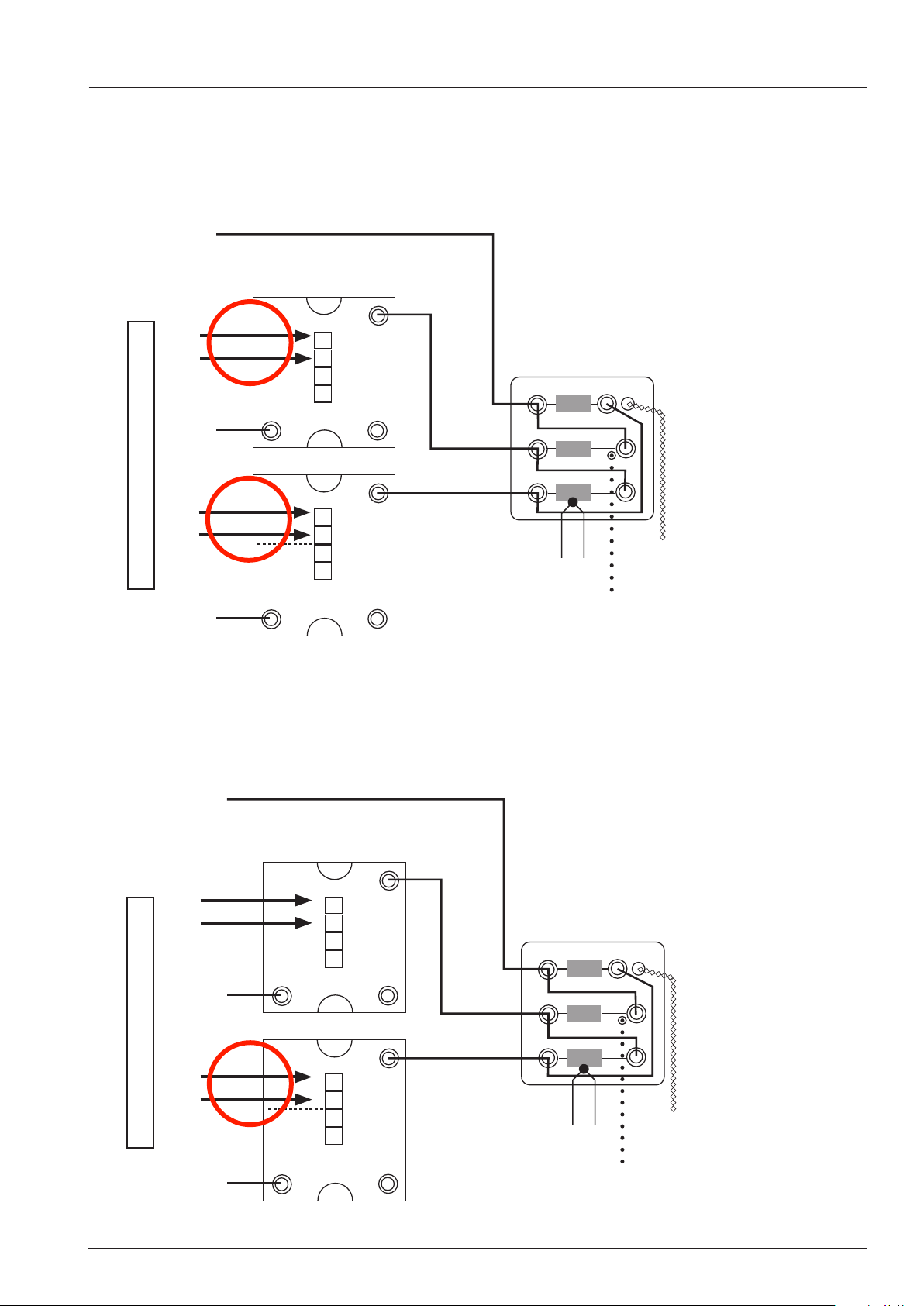
SSR 100% - 50% power at 3AC 200-240V
Control of SSR steam element at 100% energy demand
Delta connection 3AC 200-240V
L3
Violet
A1/B1 - A2 Steam / Dampf
A1/B1 - B2 Hot Air / Heißluft
12V DC
0V DC
+
-
+
-
A1/B1
P
L2
A2
A
B
B2
Orange
C
B
12V DC
Steam generator
0V DC
safety thermostat 160°C
+
-
+
-
Thermocouple B5
A1/B1
A2
A
B
B2
Black
B5
L1
Control of SSR steam element at 50% energy demand
Delta connection 3AC 200-240V
L3
A1/B1 - A2 Steam / Dampf
A1/B1 - B2 Hot Air / Heißluft
0V DC
0V DC
+
-
+
-
A1/B1
P
L2
A2
A
B
B2
Violet
Orange
C
B
12V DC
Steam generator
0V DC
safety thermostat 160°C
+
-
+
-
Thermocouple B5
A1/B1
A2
A
B
B2
Black
B5
L1
- 33 - V02 en, SCC_WE
Page 34
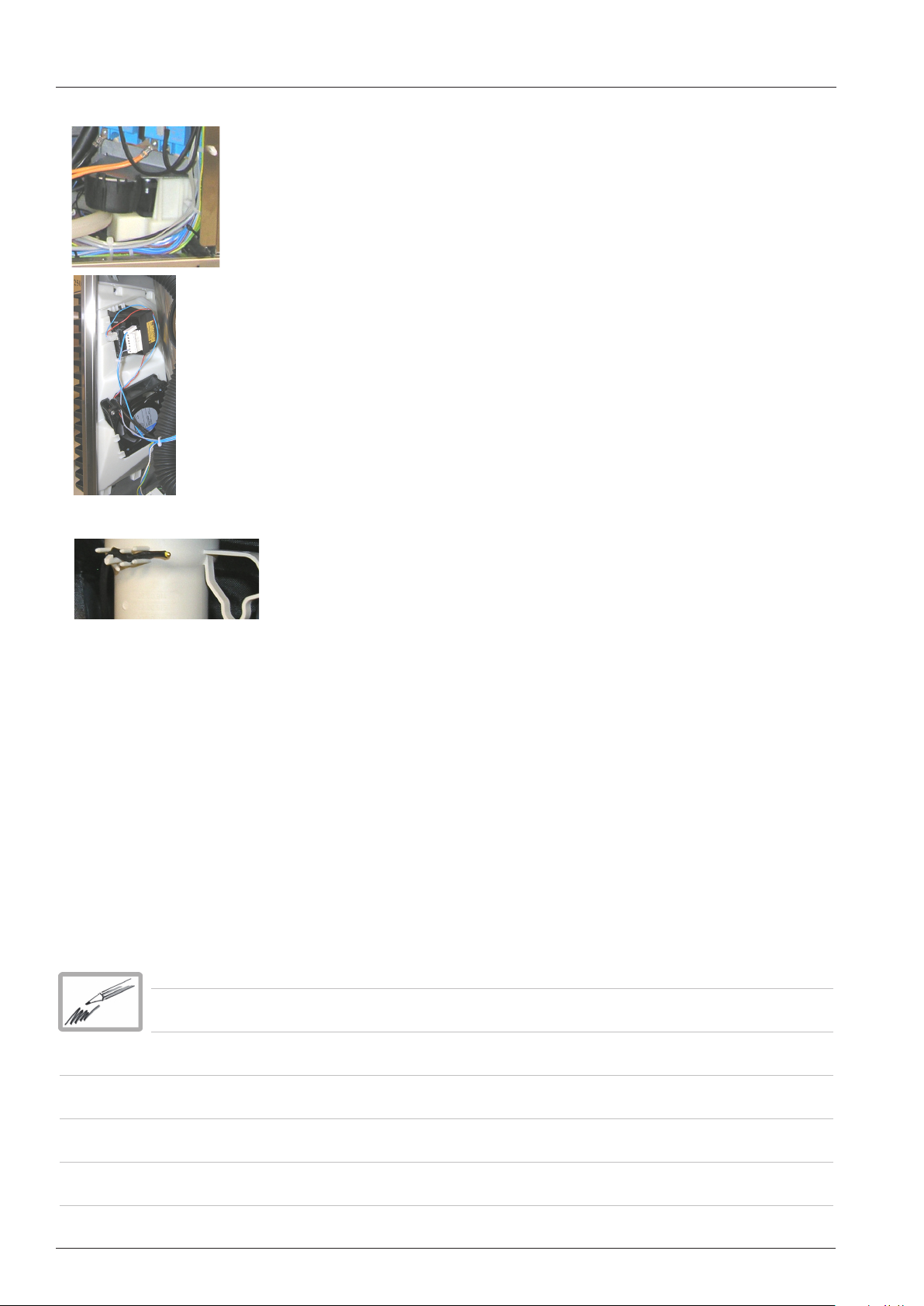
Control of cooling fan
The supply air cooling fan for units 61 - 102 behind the control panel is
controlled by a converter 230V AC - 24V DC.
The air filter under the control panel can be replaced by simply unlocking
it from the base frame.
The cooling air is discharged through the bottom of the unit.
The supply air cooling fan 201-202 on the rear left back panel is controlled
by a transformer pri. 230V AC, sek. 12V DC.
The air filter can only be changed after dislodging the protection cover
and sliding it to the right side.
The cooling air is discharged through the top left side of the rear panel.
Both supply air cooling fans are equipped with a temperature sensor
(NTC). This sensor measures the temperature at the position of the clima
valve Y5. The speed of the cooling fan increases with increasing temperature.
This sensor can not be changed separately.
The DC (supply air) cooling fan always runs when either of the following conditions are given:
B4 Temperature is above 130°C (266°F) or the CPU temperature is above 60°C (140°F) or any cooking
process is selected.
Additional 230V cooling fans distribute the cooling air in the electrical cabinet and cool the SSRs.
If the pcb reaches a temperature of 65°C (149°F) - depending on unit type- , “Change air filter” will be
displayed. If a temperature of 80°C (176°F) is reached, any running cooking mode or program will be
terminated and error “Service 29” is displayed.
V02 en, SCC_WE - 34 -
Page 35
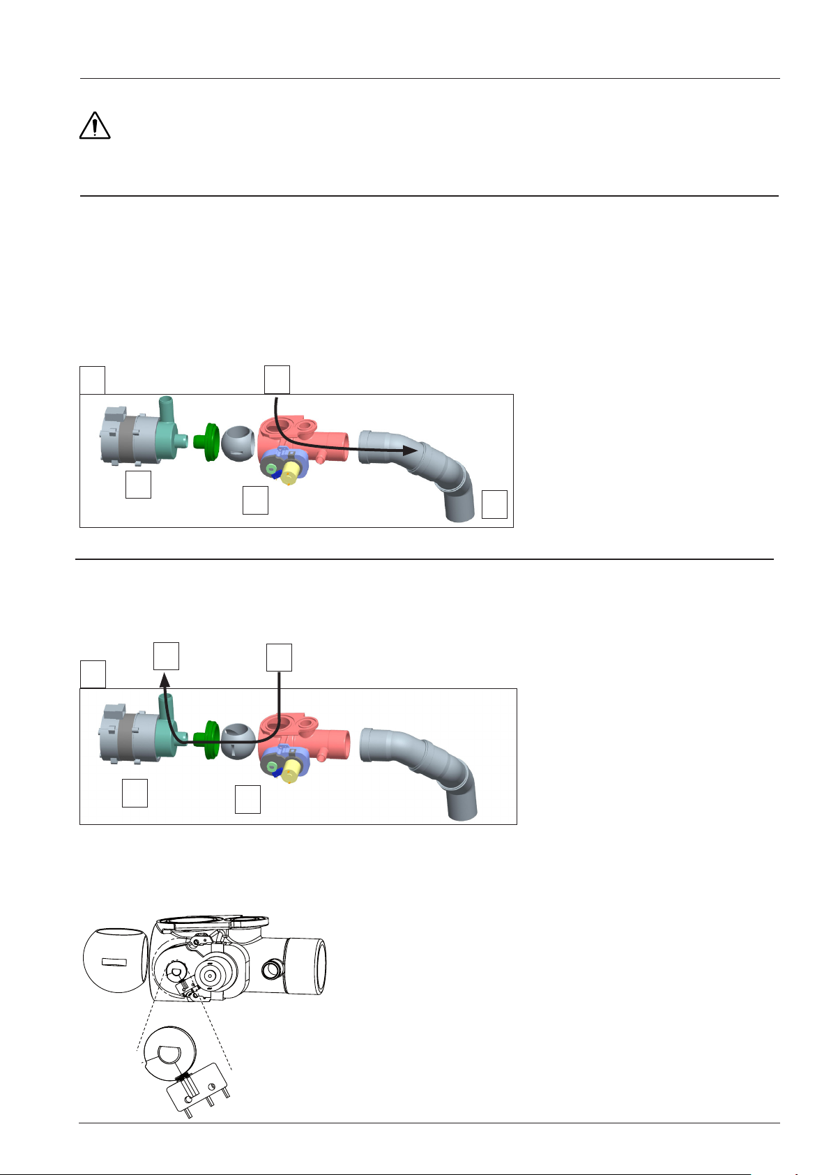
Control of drain valve
1
0
When switching on the SCC unit the drain valve automatically starts to initialise, this means it
tries to find the correct end position. This end position is the open position of the ball valve (position for cooking).
If this doesn‘t work, „Service 26“ will be indicated
(see also Basic Setting, t0 and t1, 1/4 and 3/4 turn)
A: Position for cooking
1. Drain valve with motor and limit switch
2. CleanJet Pump
3. Waste water from quenching box
4. CleanJet solution from quenching box
5. Drain of the unit
6. CleanJet solution to cooking cabinet
A
3
2
1
B: Only during CleanJet and Care in certain process steps the drain valve will be closed
(position CleanJet and Care)
6
4
5
B
2
In function test it is possible to rotate the drain valve manually clockwise or anti clockwise. This
can be necessary if the drain valve is jammed.
- 35 - V02 en, SCC_WE
1
The drain valve is in open position, when the micro
switch S12 changes from 0 to 1 when opening in
function mode.
The drain valve is in closed position, when the micro switch S12 changes from 0 to 1 when closing in
function mode.
Page 36
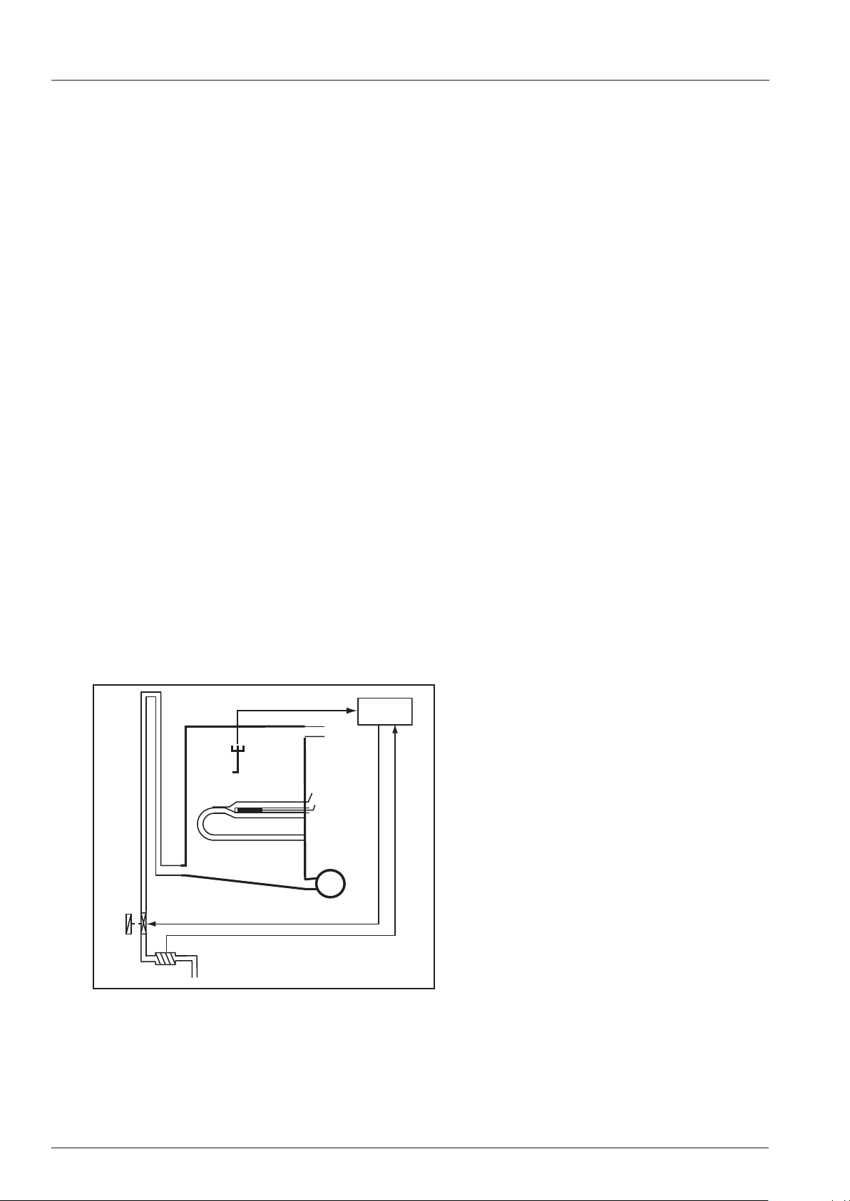
CDS
1.Basics
During steam production the concentration of minerals in water of the steam generator increases.
These minerals deposit in the steam generator and build up scale.
The build up of scale is influenced by the local water hardness and the individual usage of the
unit. The SCC unit continuously calculates the scale amount inside the steam generator.
This value is also used for calculating the number of indicated rinse tabs in CareControl.
2. Function description
At the end of the SC-automatic the steam generator will be filled. Solenoid valve Y1 opens and
water flows into the steam generator via the CDS sensor. During this filling phase S11 (CDS Sensor) creates pulses (1000 Pulses = 1l). When the water reaches the level electrode S2, the filling
will be stopped and the measured number of pulses are stored. The unit specific nominal filling
volume is stored in the CPU and will be compared with the actual filling volume (calculated from
the pulses).
The higher the difference between nominal- and actual filling volume, the more scale has built
up in the steam generator and therefore also the number of indicated bars in the Care display
increases.
When cleaning the unit regularly as requested, using the „CARE“ tabs the built up of scale in
the steam generator will be avoided and the CDS pulses remain constant.
CPU
S2
B5
F3
M4
Y1
S11
V02 en, SCC_WE - 36 -
Page 37
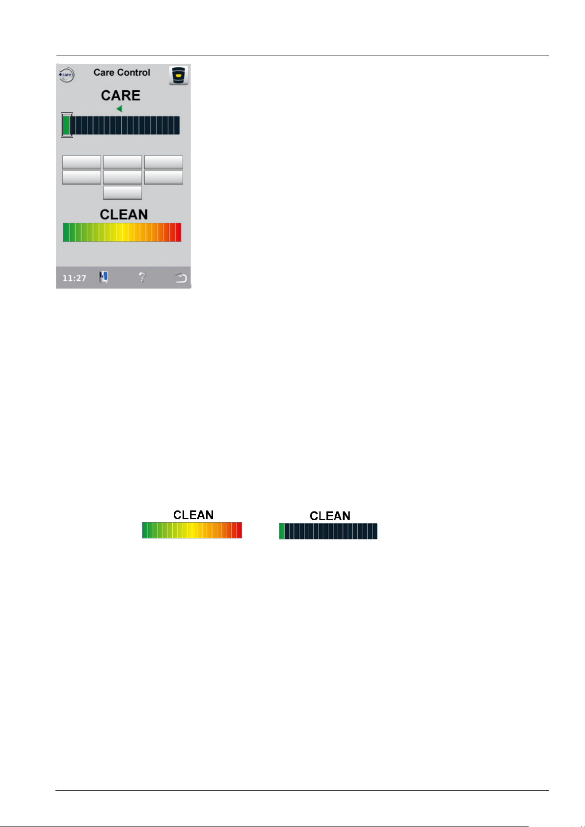
CareControl
The condition of the indication depends on:
a: the use of the unit
b: the cleaning behaviour of the customer
c: the degree of scale in the steam generator (see information
CDS).
Display Care
1: very good care - only one green bar visible.
2: medium care - yellow bars are visible
3: neglected care - red bars are visible
The request for Clean+Care has been neglected several times.
Only regular cleaning will reduce the display to one green bar again.
Display Clean
Actual dirt status
1: Only green bars visible - no cleaning necessary
2: Yellow bars visible - CleanJet request will show soon
3: red bars visible - Cleaning urgently required
CleanJet request is dependent on the usage pattern of the unit:
- SCC processes
- manual modes
- cooking programs
- duration
- temperatures
Using any of the Cleanjet programs: Quick, Save, Medium or Strong will reset the bars of the Display
Clean to 1 green bar (starting with software version 05-00-09).
CleanJet +Care can only be started when the cabinet temperature is below 50°C (122°F).
- 37 - V02 en, SCC_WE
Page 38

Function during CleanJet+Care
Sequence of Cleanjet Program Light, Medium, Strong
Component test
1. SC pump is activated until level electrode senses low water.
2. Y1 filling solenoid is activated (control by CDS)
3. Y3 moistening solenoid is activated (control by CDS)
4. Y4 Care solenoid is activated (control by CDS)
5. Y1-Y3-Y4: all solenoid valves are switched off, CDS shall not send any pulses.
CleanJet Phase
6. M7 drain valve closes
7. Y3 moistening solenoid brings water into the quenching box (CDS controlled)
(In case the moistening nozzle is blocked water is brought either by quenching solenoid Y2
(time based) or pumped from the steam generator into the quenching box (time based)
- depending on CJ step)
8. M6 Cleanjet pump pumps water through the cabinet (water flow is detected by amp draw of
motor)
9. M7 drain valve opens and dirty water is released.
(steps 6 - 9 are repeated dependent on cleanjet program light, medium or strong)
Care Phase
10. Y4 Care solenoid fills care container twice with water. The water with the dissolved care
chemical is pumped each time into the steam generator with the care pump M12.
11. M7 drain valve closes.
12. Y1 filling solenoid fills the steam generator with water up to the level electrode.
13. M4 SC pump is activated for a few seconds to pump some of the content of the steam
generator into the quenching box.
14. Y1 filling solenoid refills the steam generator higher than the level electrode.
15. Y3 moistening solenoid tops up the quenching box.
16. SSR - water in the steam generator is preheated up to 80°C (176°F)
17. M6 Cleanjet pump pumps water (rinse) through the cabinet.
18. M7 drain valve opens and water is released.
19. M4 SC pump empties steam generator.
20. Steam generator is flushed several times, cabinet will be steamed for a few minutes.
V02 en, SCC_WE - 38 -
Page 39
CleanJet: Error messages - Abort program
Depending on real steam production time or when the scale deposit inside the steam generator is
below 4%, only a small number of Care Tabs is indicated and steps 12, 14, 16 and 19 are skipped (no
descaling of steam generator, shorter CleanJet+Care process). The entire content of the steam gen-The entire content of the steam generator is pumped into the quenching box.
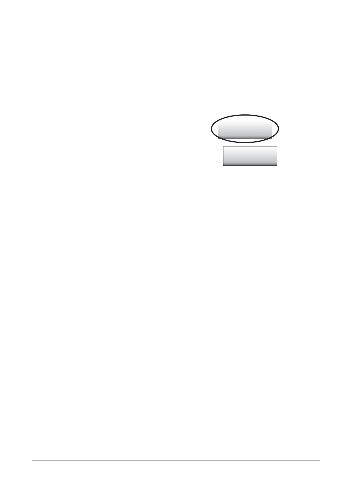
Above 4% scale the Descaling tab (starting of descaling program)
will be shown under Service.
The customer will be informed that soon a descaling
will be needed. This information can be quitted.
Reaching 16% the customer will be informed that descaling
is urgently needed. This information will be active for 2 minutes
Service
Descaling
Possible error messages during CleanJet +Care
Problem Cancel error indication by:
Step 1: Service 10 SC pump Follow fault tree
Step 2: Low water Y1, water tap Solve reason for low water
indication (water tap etc)
Step 3: Service 41 Y3, moistening blocked (CDS) Rinse without tabs
Step 4: Service 42 Y4, care valve blocked (CDS) Rinse program
Step 5: Service 43 Y1, Y3, Y4 valve leaking (CDS) Rinse program
Step 12: Service 40 Care pump, Care hose Rinse program
Step 13: Service 110 SC pump, level electrode Abort program
Step 14: Service 120 Care pump, level electrode Abort program
Step 15: Service 44 Steam heating (B1) Rinse program
An interrupt of the CleanJet processes is possible.
The duration of the following interrupt program is approximately 27 minutes.
The cabinet will be flushed with CleanJet pump M6. Tthe steam generator will be filled with the Care
valve Y4. Then the steam generator will be emptied with SC Pump M4 and then overfilled with the
solenoid valve filling Y1. Now the steam generator will be emptied once again with SC Pump M4 and
then refilled. Finally there is a short steam phase (neutralisation of the steam generator).
CleanJet interrupt program
Should a running CleanJet program be interrupted by power failure or the unit has intentionally been
switched off, an ABORT program of approx. 27min must be started to bring the unit back into safe
operation mode. This ABORT program can not be shortened or aborted again but must be completed
successfully.
- 39 - V02 en, SCC_WE
Page 40
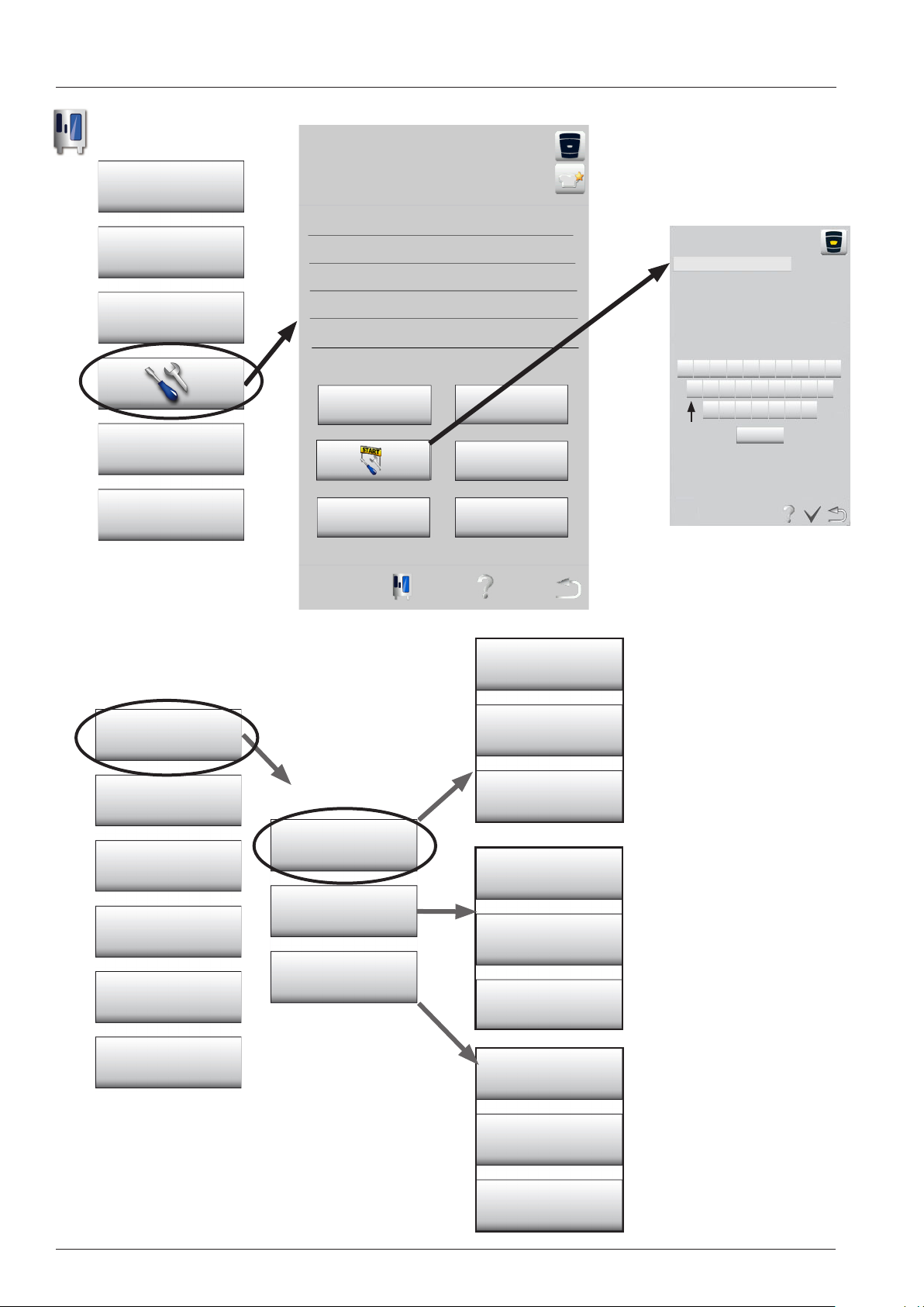
Diagnose - Real Time Data - Start
Function key
Settings
Actual service messages
HACCP
Communication
enter password
Service
Display Configurator
Service Mode
Diagnostic
Basic Settings
Unit data empty
Steam generator
descaling (>16%)
Hotline Show mode
Diagnostic
Water, Cleanjet,
Sensors
Clima
Motor, Switch
Q W E R T Z U I O P
A S D F G H J K L
Y X C V B N M
UK _+123 Äöüß
Real Time Data:
In Real Time Data all sensors
and actuators are checked for
their actual values.
Real Time Data
Function Test
Running Times
Calibration
Service History
V02 en, SCC_WE - 40 -
Components
Modes
Heating
Service error history
Gas error history
Top ign. box
Gas error history
Bottom ign. box
Running times
In Running Times all times of
actuators, cooking modes and
switches are recorded.
Service Error History
In Service Error History the
error codes are listed with their
time of rst, last and quantity
of occurance.
Page 41
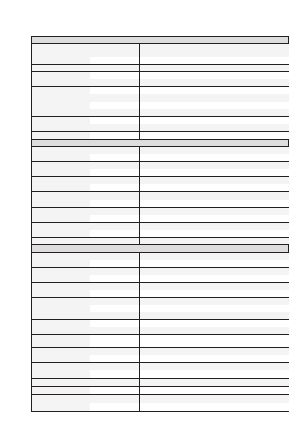
Diagnose - Real Time Data - Content
Real time data - Sensors
Act. Temperature Max Tempera-
ture
Cabinet B1
Quenching B2
Humidity B4
Steam Generator B5
Core Temp B3-1 (tip)
Core Temp B3-2
Core Temp B3-3
Core Temp B3-4
Core Temp B3-5
Core Temp B3-6 (shaft)
Temperature PCB
Real time data - Clima
Status Dry Wet combi
Clima Status RPM 1L 500 rpm Dry X Pa Wet X Pa Combi X Pa
Clima Status RPM 1R 500 rpm Dry X Pa Wet X Pa Combi X Pa
Clima Status RPM 2L 1000 rpm Dry X Pa Wet X Pa Combi X Pa
Clima Status RPM 2R 1000 rpm Dry X Pa Wet X Pa Combi X Pa
Clima Status RPM 3L 1450 rpm Dry X Pa Wet X Pa Combi X Pa
Clima Status RPM 3R 1450 rpm Dry X Pa Wet X Pa Combi X Pa
Clima Status RPM 4L 1550 rpm Dry X Pa Wet X Pa Combi X Pa
Clima Status RPM 4R 1550 rpm Dry X Pa Wet X Pa Combi X Pa
Clima valve Y5 "open" or "closed"
Clima Out P1 x.x Volt
Clima Humidity x %
Acvcepted Tolerance
Time max temperature reached
Real time data - Water, CleanJet / Care, Motor / Switch
Status Status Status Status
Filling solenoid Y1 "on" or "off"
Quenching solenoid Y2 "on" or "off"
Moistening solenoid Y3 "on" or "off"
CDS Sensor S11 1000
Level Electrode S2 "water" or "no water"
SC-Automatic Actual X min Run time X sec. Set time X min
Volume Steam generator Norm X l Fill X l Calccheck X l
SC-pump „puls“ or „continuous“
CleanJet Pump M6 "on" or "off"
Drain valve motor M7 "on" or "off"
Micro switch drain valve
S12
Care pump M12 "on" or "off"
Solenoid valve care Y4 "on" or "off"
Door Contact S3 "open" or "closed"
Motor Table/Floor M1 L/R X 1/Min
Motor Floor M2 L/R X 1/Min
Hot air 0% or 50% or 100% GAS: X uA
Steam 0% or 50% or 100% GAS: X uA
0 or 1
- 41 - V02 en, SCC_WE
Page 42
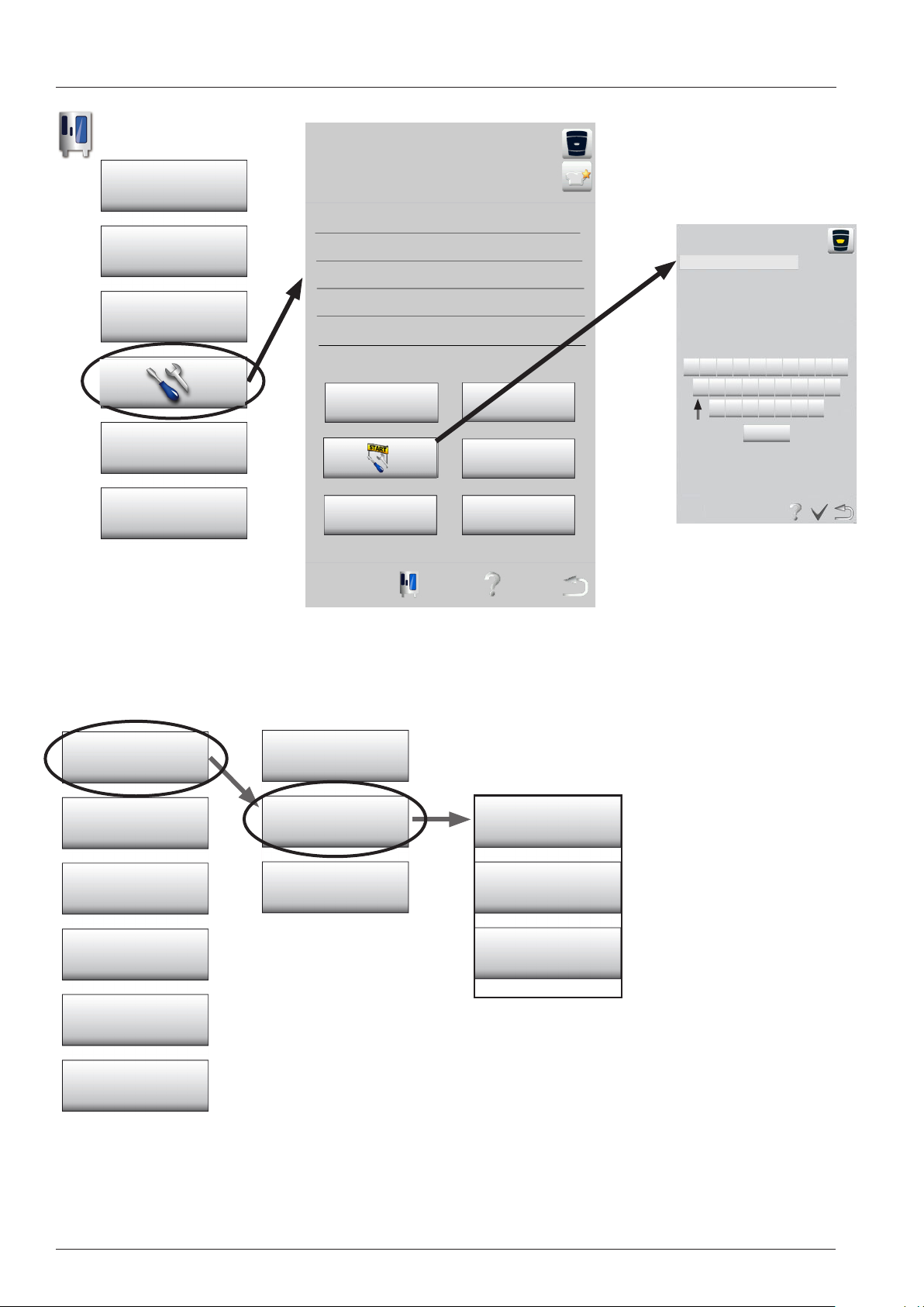
Diagnose - Running times - Start
Function key
Settings
Actual service messages
HACCP
Communication
Service
Display Configurator
Unit data empty
Steam generator
descaling (>16%)
Hotline Show mode
enter password
Q W E R T Z U I O P
A S D F G H J K L
Y X C V B N M
UK _+123 Äöüß
Service Mode
Diagnostic
Basic Settings
Function Test
Calibration
Diagnostic
Real Time Data
Running Times
Service History
Components
Modes
Heating
Running times
In Running Times all times
of actuators, cooking modes
and switches are recorded.
V02 en, SCC_WE - 42 -
Page 43
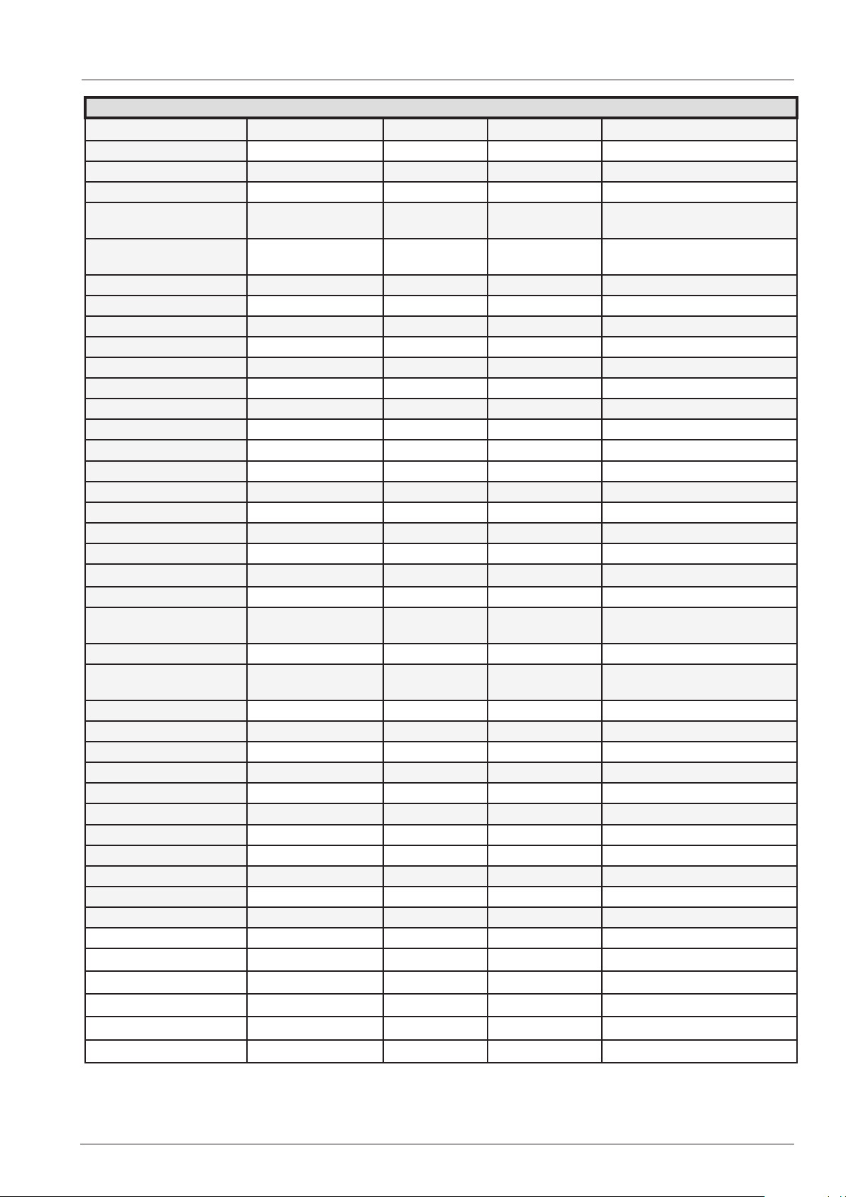
Diagnose - Running times - Content
Running times
Components Running times
Door openings S3 Reset XXXX
Ball valve openings S12 Reset XXXX
Solenoid valve filling Y1 Reset XXXX min
Solenoid valve quenching Y2Reset XXXX min
Solenoid valve moistening Y3Reset XXXX min
Solenoid valve care Y4 Reset XXXX min
Clima valve Y5 Reset XXXX
SC pump M4 Reset XXXX min
CleanJet Pump M6 Reset XXXX min
Ball valve motor M7 Reset XXXX min
Care Pump M12 Reset XXXX min
Emergency controler Reset XXXX
Modes Running times
Steam mode XXXX hrs
Hot air mode XXXX hrs
Combi steam mode XXXX hrs
Vario steam mode XXXX hrs
Finishing mode XXXX hrs
Cleanjet "rinse without
tabs"
CleanJet "rinse" XXXX hrs
CleanJet "Interim
cleaning"
CleanJet „Quick“
CleanJet "Save" XXXX hrs
CleanJet "Medium" XXXX hrs
CleanJet "Strong" XXXX hrs
Cool down XXXX hrs
Total running time unit XXXX hrs
Heating Running times
Steam heating time Reset XXXX hrs
Hot air heating time Reset XXXX hrs
XXXX hrs
XXXX hrs
- 43 - V02 en, SCC_WE
Page 44
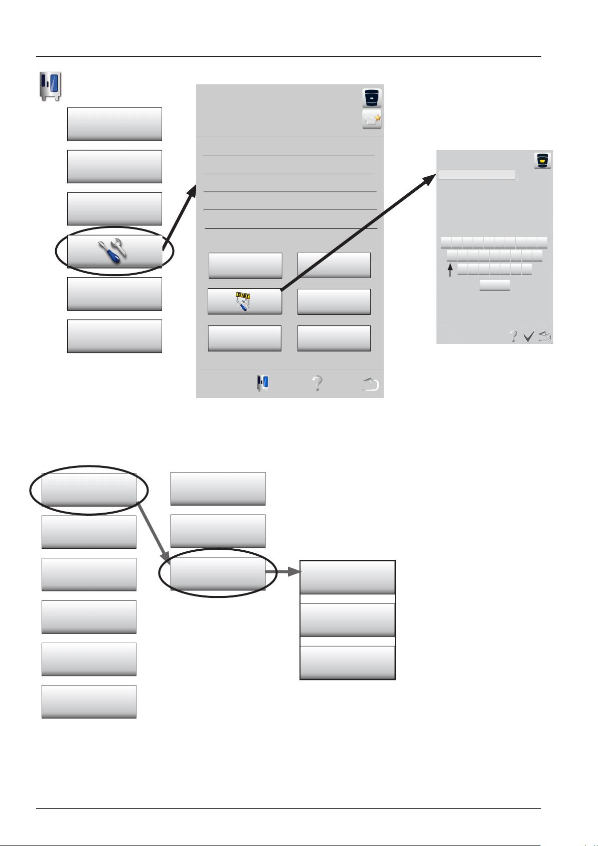
Diagnose - Service error history - Start
Function key
Settings
Actual service messages
HACCP
Communication
enter password
Service
Display Configurator
Service Mode
Diagnostic
Basic Settings
Unit data empty
Steam generator
descaling (>16%)
Hotline Show mode
Diagnostic
Real Time Data
Running Times
Q W E R T Z U I O P
A S D F G H J K L
Y X C V B N M
UK _+123 Äöüß
Function Test
Calibration
Service History
V02 en, SCC_WE - 44 -
Service error history
Gas error history
Top ign. box
Gas error history
Bottom ign. box
Service Error History
In Service Error History the
error codes are listed with
their time of rst, last and
quantity of occurance.
Page 45
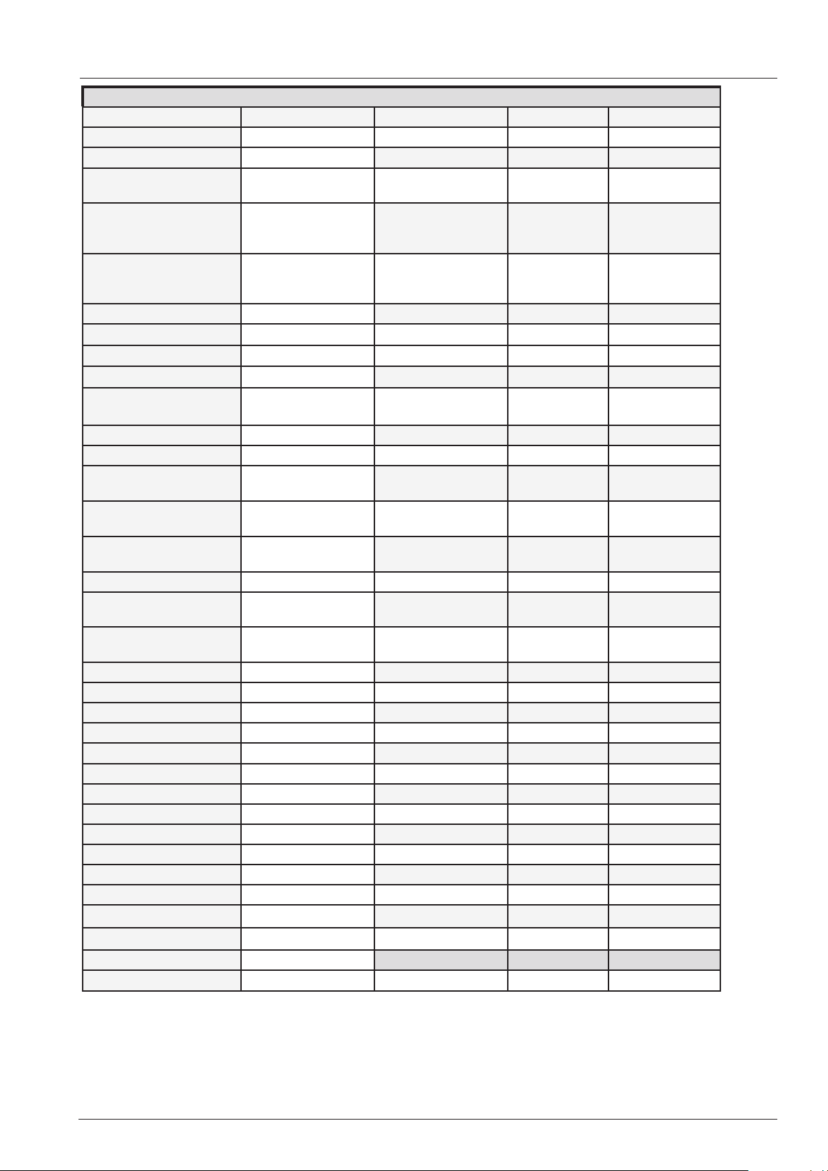
Diagnose - Service error history - Content
SCC Service Error History first appearence counter last appearance
Service 10
Service 11
Service 12
Service 13
Service 14
Service 16
Service 17
Service 18
Service 19.1
Service 20
Service 23
Service 24
Service 25
Service 26
Service 27
Service 28
Service 29
Service 30
Service 31
Service 32
Service 33
Service 34
Service 35
Service 36
Service 37
Service 40
Service 41
Service 42
Service 43
Service 44
Service 60
Service 63
Service 110
Service 120
SC pump
CDS sensor
CDS sensor without
signal
Steam generator is
not refilled during
steam mode
Level electrode
doesn`t recognise
water;
Software structure
SD card
SD card
SD card.
Thermocouple
defective
SSR Steam
SSR Hot air
No water flow detected during CleanJet
Drain valve
permanently closed
Drain valve doesn‘t
close
Thermocouple B5 a
PCB temperature
above 85°C (185°F)
Emergancy humidity
control
Core probe faulty
Ignition box faulty
Ignition box faulty
Bus signal
Ultravent
P1 defective
P1 out of range
Care pump
Moistening valve
Care valve
Y1, Y3 or Y4 dleaking
steam heating
ignition box
selftest without water;
SC Pumpe
Level electrode
hr:min:sec dd:mm:yyyy X times time and date
hr:min:sec dd:mm:yyyy X times time and date
hr:min:sec dd:mm:yyyy X times time and date
hr:min:sec dd:mm:yyyy X times time and date
hr:min:sec dd:mm:yyyy X times time and date
hr:min:sec dd:mm:yyyy X times time and date
hr:min:sec dd:mm:yyyy X times time and date
hr:min:sec dd:mm:yyyy X times time and date
hr:min:sec dd:mm:yyyy X times time and date
hr:min:sec dd:mm:yyyy X times time and date
hr:min:sec dd:mm:yyyy X times time and date
hr:min:sec dd:mm:yyyy X times time and date
hr:min:sec dd:mm:yyyy X times time and date
hr:min:sec dd:mm:yyyy X times time and date
hr:min:sec dd:mm:yyyy X times time and date
hr:min:sec dd:mm:yyyy X times time and date
hr:min:sec dd:mm:yyyy X times time and date
hr:min:sec dd:mm:yyyy X times time and date
hr:min:sec dd:mm:yyyy X times time and date
hr:min:sec dd:mm:yyyy X times time and date
hr:min:sec dd:mm:yyyy X times time and date
hr:min:sec dd:mm:yyyy X times time and date
hr:min:sec dd:mm:yyyy X times time and date
hr:min:sec dd:mm:yyyy X times time and date
hr:min:sec dd:mm:yyyy X times time and date
hr:min:sec dd:mm:yyyy X times time and date
hr:min:sec dd:mm:yyyy X times time and date
hr:min:sec dd:mm:yyyy X times time and date
hr:min:sec dd:mm:yyyy X times time and date
hr:min:sec dd:mm:yyyy X times time and date
hr:min:sec dd:mm:yyyy X times time and date
hr:min:sec dd:mm:yyyy X times time and date
first appearence counter last appearance
hr:min:sec dd:mm:yyyy X times time and date
- 45 - V02 en, SCC_WE
Page 46
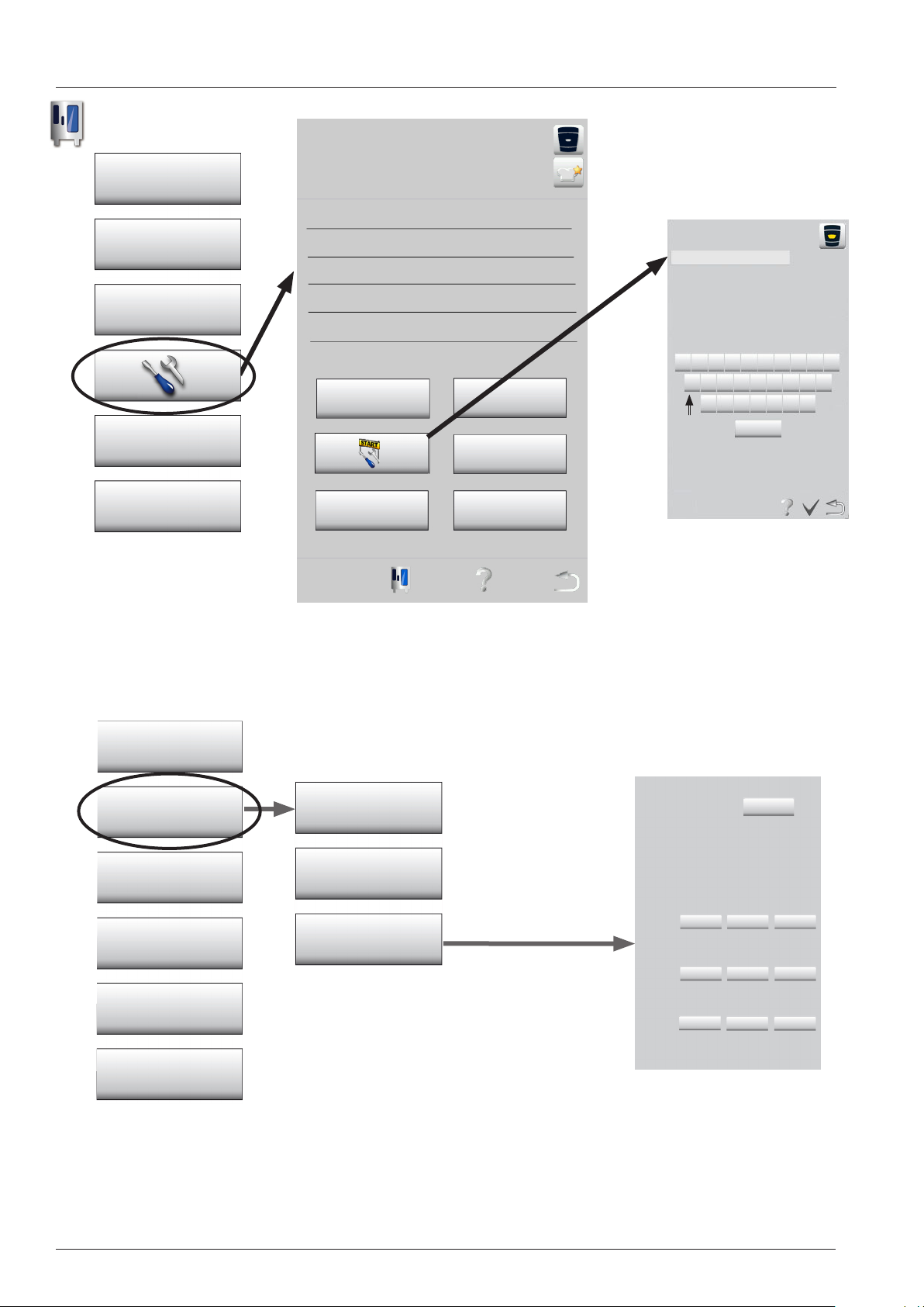
Basic settings - Start
Function key
Settings
HACCP
Communication
Actual service messages
enter password
Service
Display Configurator
Service Mode
Diagnostic
Basic Settings
Function Test
Calibration
Unit data empty
Steam generator
descaling (>16%)
Hotline Show mode
Basic Settings
Water
General settings
Ultravent
Self test
Telefon
Gassystem
Basic Settings:
In Basic Settings all unit specific data
according to unit size, energy and
connections are set.
Q W E R T Z U I O P
A S D F G H J K L
Y X C V B N M
UK _+123 Äöüß
Training manual Gas
Gas: G20
RPM Correction 600m(ST) 500m(P1)
Ultravent: Yes / no
Gas blower settings:
Steam: Start Min Max
rpm 2500 1800 5800
default 2500 1800 5800
C02 screw: 4,8mm CO2 min: 8.7% CO2 max: 9.4%
Hot Air top: Start Min Max
rpm 4000 1900 6100
default 4000 1900 6100
C02 screw: 5,5mm CO2 min: 8.6% CO2 max: 9.4%
Hot Air bottom: Start Min Max
rpm
default
C02 screw:
In order to store any changes made
the unit must be switched off and on
again.
V02 en, SCC_WE - 46 -
Page 47
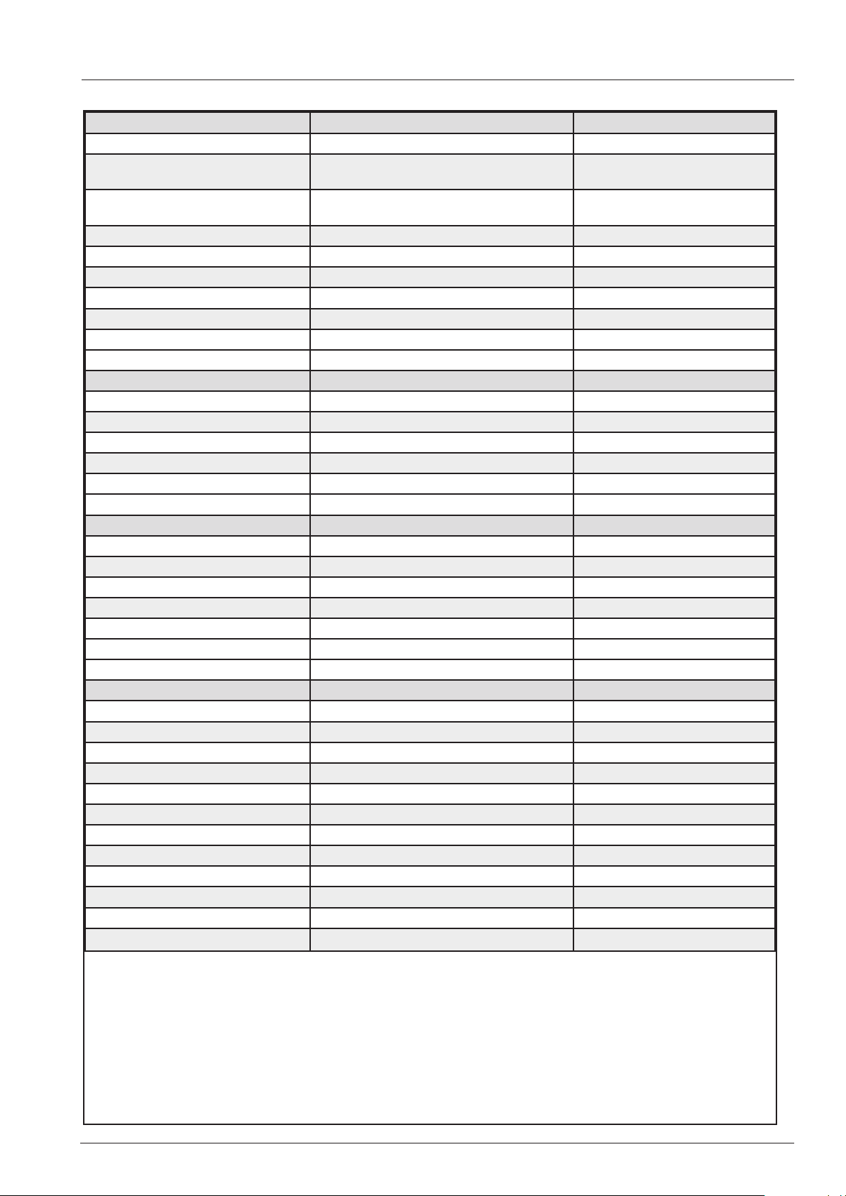
Basic settings - Content
Water Status Factory Setting, Detected values
CDS sensor 1000 1000
Volume steam generator new after
manual descaling
Volume steam generator new after
steam generator replacement
SC pump: set pump duration X sec
SC pump: mode Continuous oder Puls
SC pump: set interval time X min
Quenching temperature hot air XX°C
Quenching temperature steam XX°C
Cleanjet / Care
Drain valve Start t1 XX s, t2 xx s
Steam corrosion control "on" oder "off"
Softwater „on“ oder „off“
Care Control Reset
XX l
XX l
Phone numbers, UltraVent, Selftest
Service Phone Setting edit
Chef line phone setting edit
Deactivate UltraVent deact
Selftest off
Deactivate interior light on - off
Gassystem Data
Gas type Nat. H
RPM Correction Selftest - P1 cold - Factory value
Ultravent on / off
Gasblower speed steam Start rpm XXXX (factory XXXX)
Gasblower speed steam Min rpm XXXX (factory XXXX)
Gasblower speed steam Max rpm XXXX (factory XXXX)
Gasblower speed hot air top Start rpm XXXX (factory XXXX)
Gasblower speed hot air top Min rpm XXXX (factory XXXX)
Gasblower speed hot air top Max rpm XXXX (factory XXXX)
Gasblower speed hot air bottom Start rpm XXXX (factory XXXX)
Gasblower speed hot air bottom Min rpm XXXX (factory XXXX)
Gasblower speed hot air bottom Max rpm XXXX (factory XXXX)
- 47 - V02 en, SCC_WE
Page 48
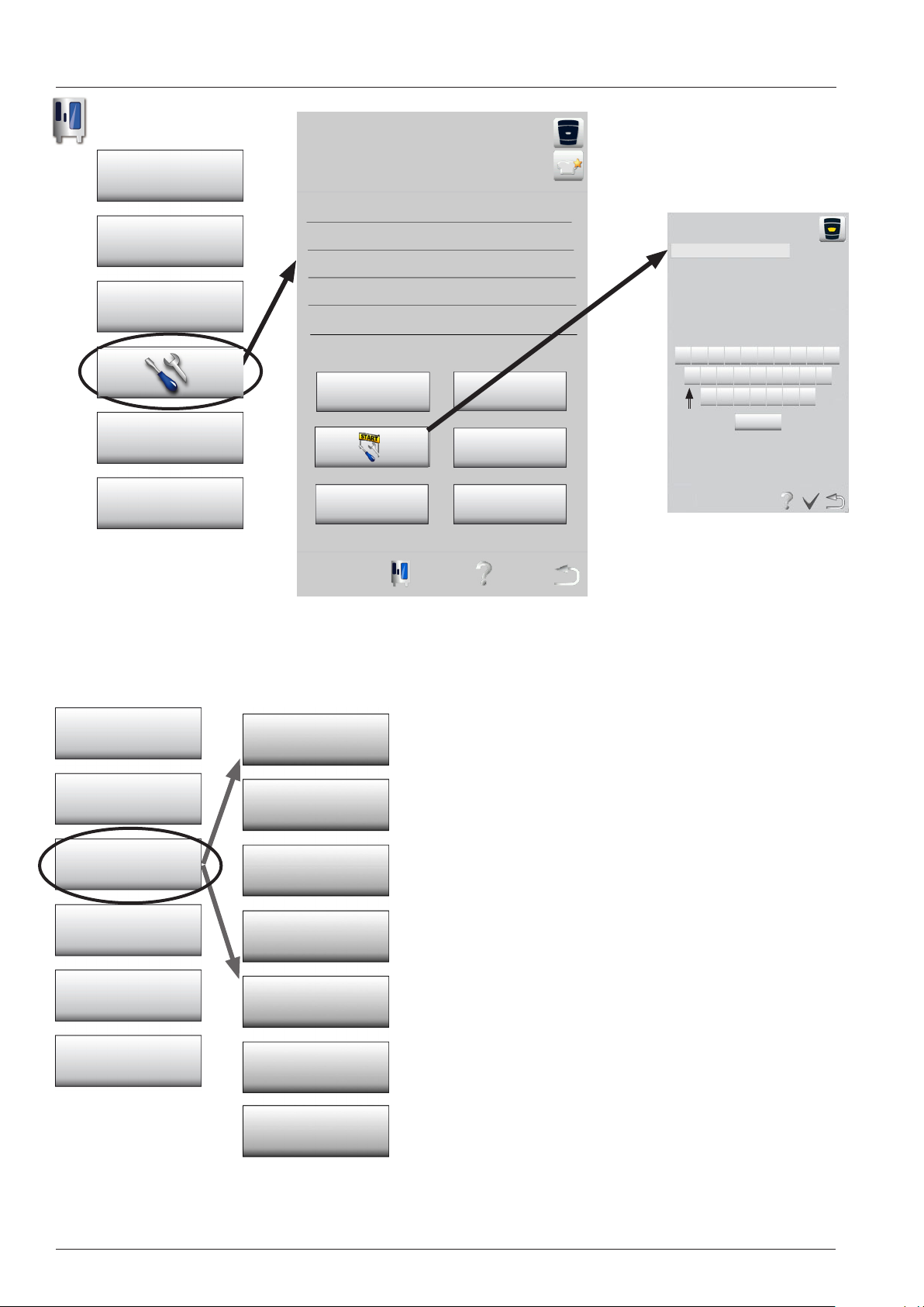
Function test - Start
Function key
Settings
HACCP
Communication
Actual service messages
enter password
Service
Display Configurator
Service Mode
Diagnostic
Basic Settings
Unit data empty
Steam generator
descaling (>16%)
Hotline Show mode
Function Test
Heating / Motor
Water
Q W E R T Z U I O P
A S D F G H J K L
Y X C V B N M
UK _+123 Äöüß
In function test all components can be operated individually
to test function and electrical connections.
Heating / Motor
All heating elements, fan motor
Water / CleanJet
Solenoid valves, pumps
Function Test
Calibration
Motor
Cleanjet
Components
Components
Clima valve, Display, loudspeaker
Gas Burner
Flue Gas Analysis
Ignition box, Gas valve, Gas blower, Burner
Flue Gas Analysis
Control of gas burner at specified load setting for 4 minutes
max.
Please relate to Training Manual Gas.
V02 en, SCC_WE - 48 -
Page 49
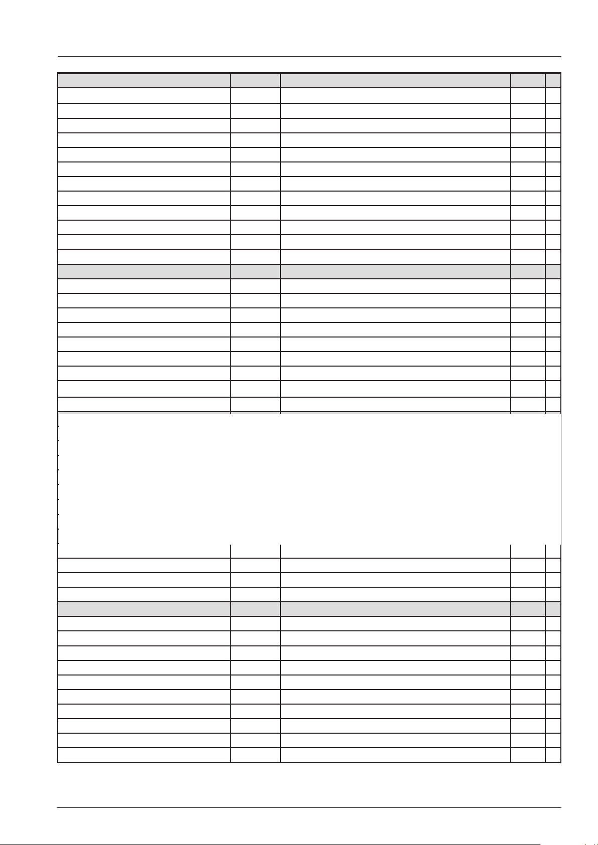
Function test - Content
Heating/Motor Status Values
Steam 50% 0 or 1 B5 = X°C Start
Steam 100% 0 or 1 B5 = X°C Start
Hot air 50% 0 or 1 B1 = X°C Start
Hot air 100% 0 or 1 B1 = X°C Start
Fan Motor top Speed 1R Actual Speed X rpm Start
Fan Motor top Speed 1L Actual Speed X rpm Start
Fan Motor top Speed 3R Actual Speed X rpm Start
Fan Motor top Speed 3L Actual Speed X rpm Start
Fan Motor bottom Speed 1R Actual Speed X rpm Start
Fan Motor bottom Speed 1L Actual Speed X rpm Start
Fan Motor bottom Speed 3R Actual Speed X rpm Start
Fan Motor bottom Speed 3L Actual Speed X rpm Start
Water/CleanJet Status Values
Solenoid valve filling Y1 0 or 1 Level electrode S2: water or low water Start
SC Pump M4 0 or 1 Level electrode S2: water or low water Start
Solenoid valve quenching Y2 0 or 1 B2 = X°C Start
Solenoid valve moistening Y3 0 or 1 Start
Care valve Y4 + Pump M12 0 or 1 Level electrode S2: water or low water Start
Cleanjet Pump M6 0 or 1 Start
Drain valve motor M7 direction1 0 or 1 End switch S12: 0 or 1 Start
Drain valve motor M7 direction2 0 or 1 End switch S12: 0 or 2 Start
Functional Group Test (open)
The following functional groups can be started: a sucessfull sequence will generate „OK“
Care
CleanJet
Steam generator management
Humidity control
Selftest
Components Status
Loudspeaker T2 0 or 1 Start
Interior light 0 or 1 Start
Display test Start
Ultravent 0 or 1 Start
Gas Burner Status Values
Gas steam blower Max 0 or 1 CO2: XX% Flame current: XX uA RPM:XXXX Start
Gas steam blower Start 0 or 1 CO2: XX% Flame current: XX uA RPM:XXXX Start
Gas steam blower Min 0 or 1 CO2: XX% Flame current: XX uA RPM:XXXX Start
Gas hot air blower top Max 0 or 1 CO2: XX% Flame current: XX uA RPM:XXXX Start
Gas hot air blower top Start 0 or 1 CO2: XX% Flame current: XX uA RPM:XXXX Start
Gas hot air blower top Min 0 or 1 CO2: XX% Flame current: XX uA RPM:XXXX Start
Gas hot air blower bottom Max 0 or 1 CO2: XX% Flame current: XX uA RPM:XXXX Start
Gas hot air blower bottom Start 0 or 1 CO2: XX% Flame current: XX uA RPM:XXXX Start
Gas hot air blower bottom Min 0 or 1 CO2: XX% Flame current: XX uA RPM:XXXX Start
- 49 - V02 en, SCC_WE
Page 50
Calibration - Start
Function key
Settings
HACCP
Communication
Actual service messages
enter password
Service
Display Configurator
Service Modus
Diagnostic
Basic Settings
Function Test
Calibration
Q W E R T Z U I O P
Unit data empty
Steam generator
descaling (>16%)
Hotline Show mode
A S D F G H J K L
Y X C V B N M
UK _+123 Äöüß
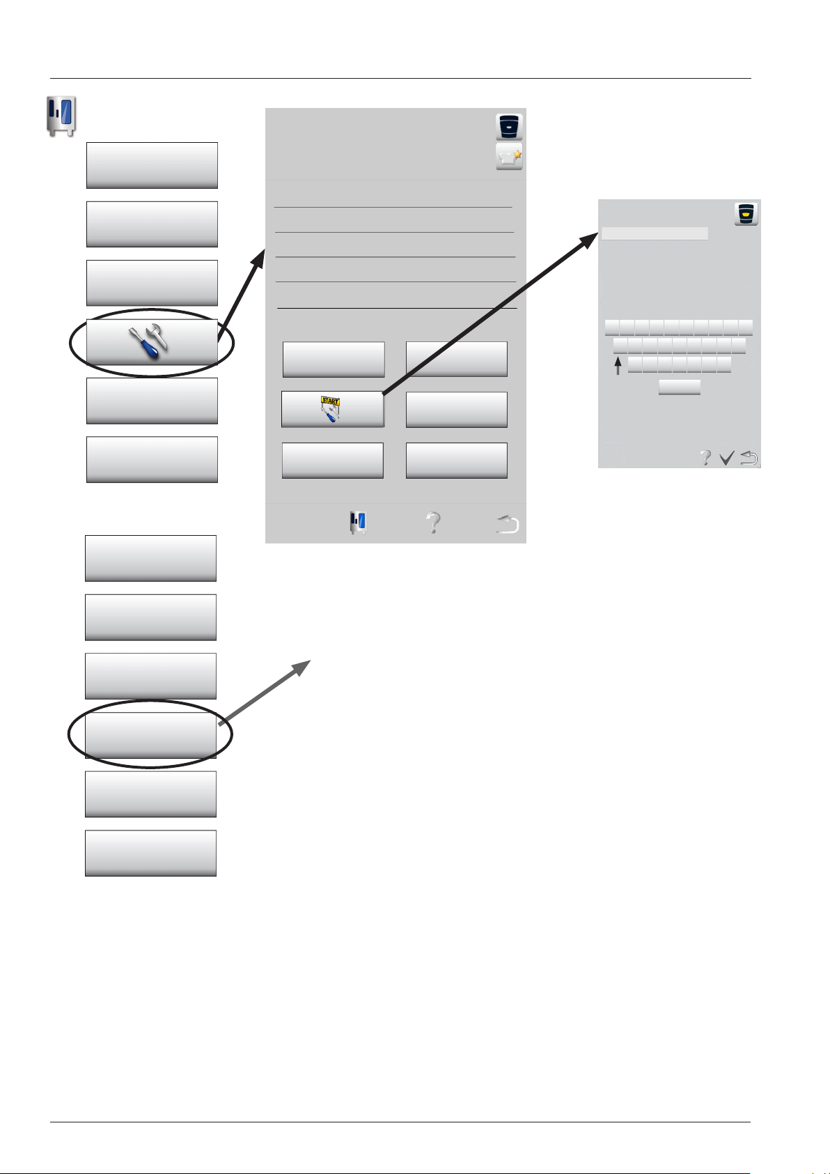
Calibration:
Different food items cook best at their specific humidity level and
specific temperature.
Vegetables are steamed, but roast is cooked at a specific humidity and mostly above 100°C (212°F)
To be able to achieve this task the unit must have stored specific
pressure values for cold and dry (40°C / 104°F), 100% steam
and combination e.g. 170°C / 338°F.
This basic information is evaluated during „selftest“ after installation or during manual calibration and stored on the PCB and SD
Card.
Manual calibration has to be done when any of the below listed service work has been carried out:
1. removing of fan wheel / motor
2. changing thermocouple B4
3. changing differential pressure sensor P1
4. installation of a Ultravent or extraction hood on top of the unit
5. installation as the lower unit of a Combi Duo after selftest as a single unit
V02 en, SCC_WE - 50 -
Page 51
Calibration - Sequence
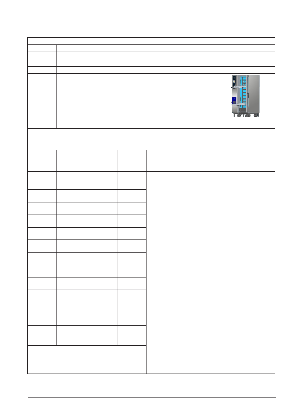
Pre condition before calibration
temperature of cooking cabinet sensor B1 is below 40°C (102°F)
temperature of quenching sensor B2 is below 40°C (102°F)
temperature of humidity sensor B4 is below 40°C (102°F)
door contact closed
heating: OFF
fan motor: OFF
left side panel closed, interior cabinet clean, if possible dry;
to achieve best calibration values insert a closed 20mm GN container
with opening facing down onto the rail closest to the center of the fan wheel
(201-202: 2 motors - 2x GN container)
Step Function possible
error
message
0 ready fo calibration Any indicated error relates to the corresponding malibration
10 checking calibration
conditions
20 Measuring Offset P1 with
fan motor not turning
100 - 115 pressure measurement cold
table unit 61 - 102
100 - 131 pressure measurement cold
floor unit 201 - 202
200 steam heating up to boiling
point without fan motor
202 steam heating with fan
motor
210 - 225 pressure measurement
steam table unit 61 - 102
210 - 241 pressure measurement
steamfloor unit 201 - 202
300 heating of cabinet to
193°C (380°F)
followed by 60 sec. to 170°C
(338°F) steady condition
301 - 316 pressure measurement
combi table unit 61 - 102
301 - 332 pressure measurement
combi floor unit 201 - 202
999 calibration sucessfull
10
200
e.g. 302
reason for error - remedy
step.
e.g. error 10 will be indicated, when the condition for calibrations is not given.
Reason: B1, B2 or B4 is above 40°C (104°F)
16 steps for each fan motor, (32 steps with floor models), e.g.
100: running fan motor at constant speed „1“
101: store P1 value at this given speed
e.g. error 200 is indicated, when the steam heating will not
reach the necessary 70°C (158°F) to detremine the boiling
point in the allocated time.
Reason: e.g. SSR (energy optimising) or gas burner is not
activated etc.
e.g. error 302 is indicated, if sensor P1 does not give any or
any valid value at this time.
Reason: P1 defective or hoses to P1 blocked by water.
These errors are indicated during the respective calibration
step is running.
After solving the problem the Selftest must be started again.
- 51 - V02 en, SCC_WE
Page 52

V02 en, SCC_WE - 52 -
Page 53
Setting Show mode - error analysis
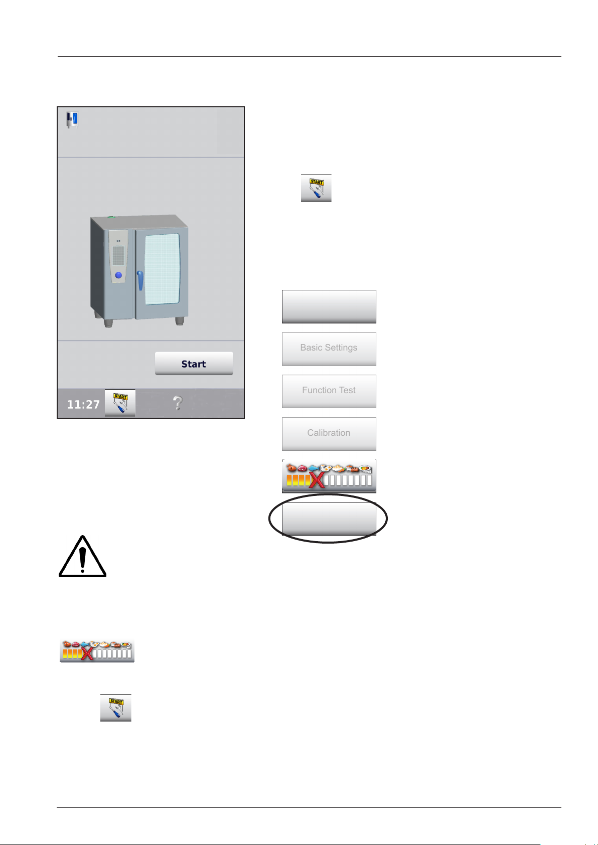
Software version from 05-00-07:
In case the unit shall be connected as a show room unit
Selfttest
(exhibition), it must be converted prior of starting the self
test.
Your SCC will carry out an automatic
self test and adjust itself perfectly to
the set-up conditions and the altitude.
In the first Sleft test display press Service
Start key
Enter password TECLEVEL
Diagnostic
Basic Settings
Function Test
Calibration
1. Press „ Process abort“ key
(all service keys will show again)
Show mode
2. Press show mode 10 seconds
3. Switch unit off and on again
In case only diagnostic mode is shown after entering the password the unit was in a running process
prior entering into service level.
Only at this same time the process abort key is shown.
Press process abort key. Now all components of Service Level are shown.
NOTE: Any running process will be terminated automatically!
In case a service error is indicated, e.g. Service 34, the service start key is indicated
at the same time.
The technician can always enter Diagnostic level via the service start key and
password.
- 53 - V02 en, SCC_WE
Page 54
Error message Service 1 - 25
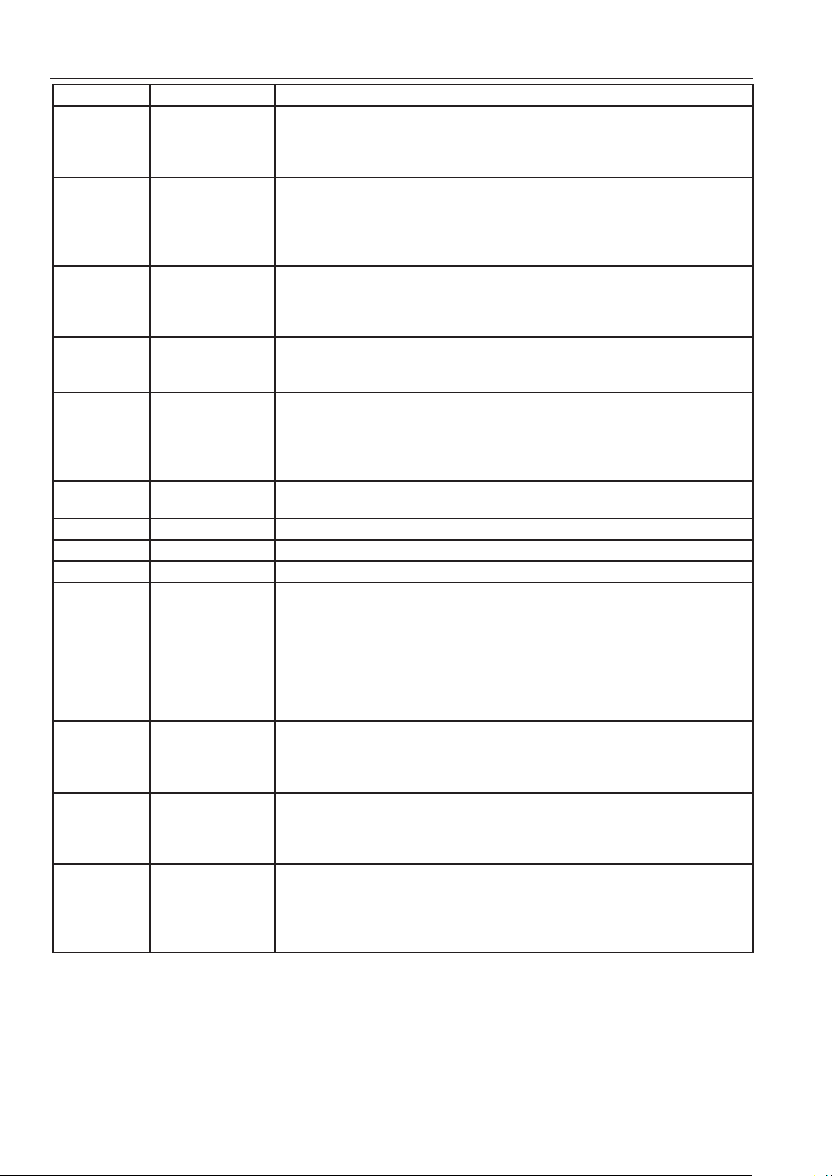
Display Definition Reason and remedy
Service 10 SC pump
Service 11 CDS sensor
Service 12 CDS sensor wit-
hout signal
Service 13 Steam generator
is not refilled during steam mode
Service 14 Level electrode
doesn`t recognise
water;
Service 16 Software structure New software data structure for SD card is older than existing data
Service 17 SD card not initialised
Service 18 SD card SD card defective
Service 19.1 SD card. SD card not inserted
Service 20 -x- Thermocouple
defective
Unit in emergancy mode, call
service;
Display 30 sec. after switch on
Display can be cancelled
SC-Automatic without function, water level always high
check SC pump and drain hose SC pump.
Display 30 sec. after switch on
Display can be cancelled
Water level o.k.
CDS sensor sends too many pulses
Check level electrode and water path to steam generator for leakage
Display 30 sec. after switch on
Display can be cancelled
Level electrode o.k.
no signal from CDS Sensor (blocked?), low water pressure
Steam generator is not refilled during steam mode => foced filling
check 0-1 signal of level electrode to PCB
Appears for 30 sec. after switch ON
Display can be cancelled by touch
Level electrode no water sensing
CDS sensor measured enough pulses;
Possible reasons: water conductivity too low, osmosis water treatment
structure on SD card.
No function when thermocoule B1 defective.
1=cabinet B1
2=quenching B2
4= humidity B4
8= steam generator B5
(e.g. 20.12 = B4 + B5)
Service 23 SSR Steam
short circuit
Service 24 SSR Hot air
short circuit
Service 25 No water flow
detected during
CleanJet
- Display at once when: Temp. B5 rises above 100°C (212°F) for 60sec.
without energy demand
- Intermittent buzzer 30 sec
- Unit without function
- Display at once when: Temp. B1 rises by 100°C (appox. 210°F) without
energy demand
- Intermittent buzzer 30 sec
- Unit without function
- Display can be cancelled
- Remove container from cabinet
- during CleanJet+Care the fan motor does not an increase in power demand when water hits the fan wheel. - check water pressure, water supply,
moisteneing valve and nozzle and CDS sensor.
V02 en, SCC_WE - 54 -
Page 55
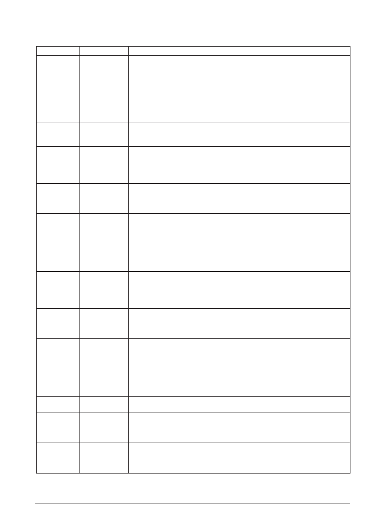
Error message Service 26 - 37
Display Definition Reason and remedy
Service 26 Drain valve
permanently
closed
Service 27 Drain valve
doesn‘t close
during initialisation
Service 28 Thermocoup-
le B5 above
180°C (356°F)
Service 29 PCB tempe-
rature above
85°C (185°F)
Service 30 Unit running in
emergancy
humidity control
Service 31.xx
buzzer
soundsca
20x / 5 Sec
Service
32.0-1-2
Service 33.1-2Ignition box
Service 34.xx Bus signal - Indication in case of bus signal problems
Service 35 Connect
Service 36 Differential
Service 37 Differential
Core probe
faulty
Ignition box
faulty
faulty
Ultravent
pressure sensor P1 defective
pressure sensor P1 no in
expected range
- Appears on time when CleanJet is selected
- Cooking not possible - drain closed
- Micro switch drain valve in permanent closed position
- Replace drain valve assembly
- Appears for 30 sec. after switch ON
- Display can be cancelled switch
- drain valve in permanent open position, CleanJet not possible
- Check micro switch drain valve
- Start rinse (abort) program
- Appears if temperature at thermocouple steam generator B5 is
above 180°C (356°F)
- Indication goes off when temperature below 110°C (230°F)
- Appears on time after switch ON until temperature is low again
- Temperature PCB above 85°C
- Check air filter, cooling fan and control panel gasket
- Check for external heat sources
- check air escape openings
- Appears for 30 sec. after switch ON
- Display can be cancelled
- Humidity control out of function
- Humidity emergency control active since more than 1 hour
-
Display 30 sec. after switch on
-
Display can be cancelled
- Combination of faults possible i.e.: 10 -->2+8)
- 1: shaft probe 2- 5th probe (close to shaft)
- 4: 4th probe 8: 3rd probe
- 16: 2nd probe 32: 1st probe in tip
- Internal Ignition box error is existing longer than 30 sec.
Change ignition box
- 0: Ignition box top
- 1: Ignition box bottom
- 2: Both Ignition boxes
- Appears after 3x Reset command without positive result
- 1: Ignition box top,
- 2: Ignition box bottom
- Check ignition wire, ignition box gas valve and gas supply.
- Main pcb can not communicate with the following parts
- Combination of faults possible i.e.: 10 -->2+8
- 1: Motor top - 2: Motor bottom
- 4: Ignition module top - 8: Ignition module bottom
- Check bus cable plug and cable for connection and damage
- when installed as a gas unit B13 (with exhaust through chimney)
check safety thermostat in draft diverter (Service 34.4, 34.8 or 34.12)
Bus signal can not be processed; Connect UV to mains power,
no signal output
Differential pressure sensor P1 no in expected range, check connection of
hoses.
- 55 - V02 en, SCC_WE
Page 56
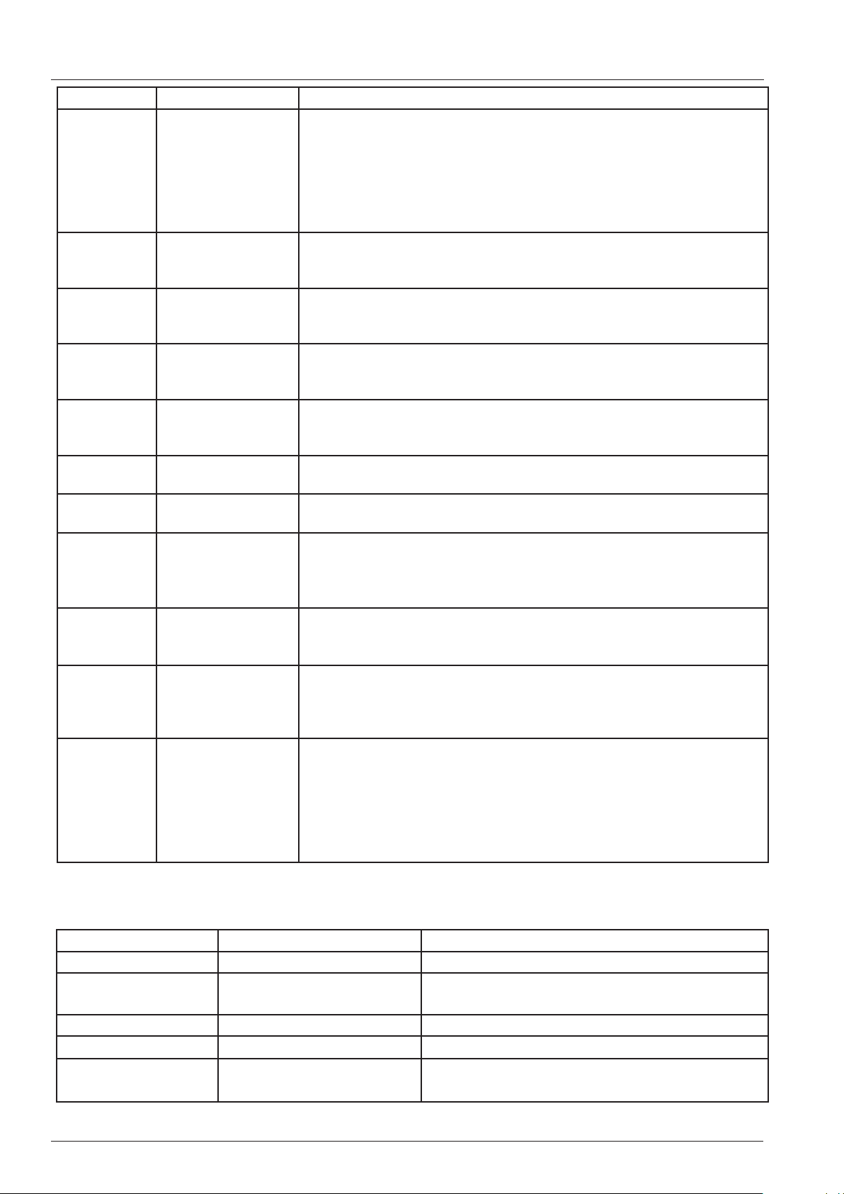
Error message Service 40 - 120, blink code motor
Display Definition Reason and remedy
Service 40 Care pump doesn`t
fill enough into
steam
generator
Service 41 Moistening without
function
Service 42 Care function not
possible, solenoid
Y4 defective
Service 43 Y1, Y3 or Y4 do not
close
Service 44 No steam hea-
ting during
Cleanjet+Care
Service 55 Blink code motor top see below
Care pump faulty or does not fill enough care solution into steam generator;
- After filling of the care solution into the steam generator the CDS sensor sends too many pulses until the level electrode recognises water.
Check if the hose from the care pump outlet is not kinked;
- Cleanjet finishes without care phase;
- Reset error by successful completing rinse program;
- Solenoid valve Y3 defective or moistening valve blocked; CDS does not
send any pulses;
- Reset error by successful completing rinse program;
- Solenoid Y4 Care defective or hose to care container blocked or
kinked; CDS does not send any pulses;
- Reset error by successful completing rinse program;
- CDS sensor sends always pulses; Solenoid Y1, Y3 or Y4 is passing
water
- Reset error by successful completing ABORT program;
- No temperature raise above 60°C recognised by B1 during steaming
time while being in Cleanjet phase
- Reset error by successful completing ABORT program;
Service 56 Blink code motor
bottom
Service 60 Initialisation of igniti-
on box incorrect
Wrong rpm information for gas blower
Service 63
Service 110 SC Pumpe not
Service 120 Level electrode
The error messages can be seen under Diagnostic, Service history.
Unit had done a selftest without water;
working while care
solution is inside
steam generator.
without signal while
care solution is
inside steam generator.
see below
Switch unit off and on again,
run SD Repair program
Cool down uinit, make sure B1, B2 and B4 is below 40°C,
In basi settings - Selftest set Selftest to ON and switch unit off and on
again. Run Selftest
- Malfunction of SC pump during the time when Care solution was inside
the steam generator,
- Reset error by successful completing ABORT program;
- After operating care pump M12 (filling care solution into steam generator) and topping up with water the level electrode does not recognise
water;
- Care Pump M12 or level electrode defective;
- Display only after twice starting filling solenoid Y1 yet no water is detected;
- Reset error by successful completing ABORT program;
Blink code Motor Reason Remedy
1x Starting error contact Rational, change motor
2x, 4x, 5x, 7x, 9x, 11x,
12x
3x, 6x, volatge error check voltage supply, change motor
8x possible starting error check fan wheel for distortion, change motor
10x only with 3AC motor
V02 en, SCC_WE - 56 -
Motor defective change motor
phase is missing
40.03.514
Page 57
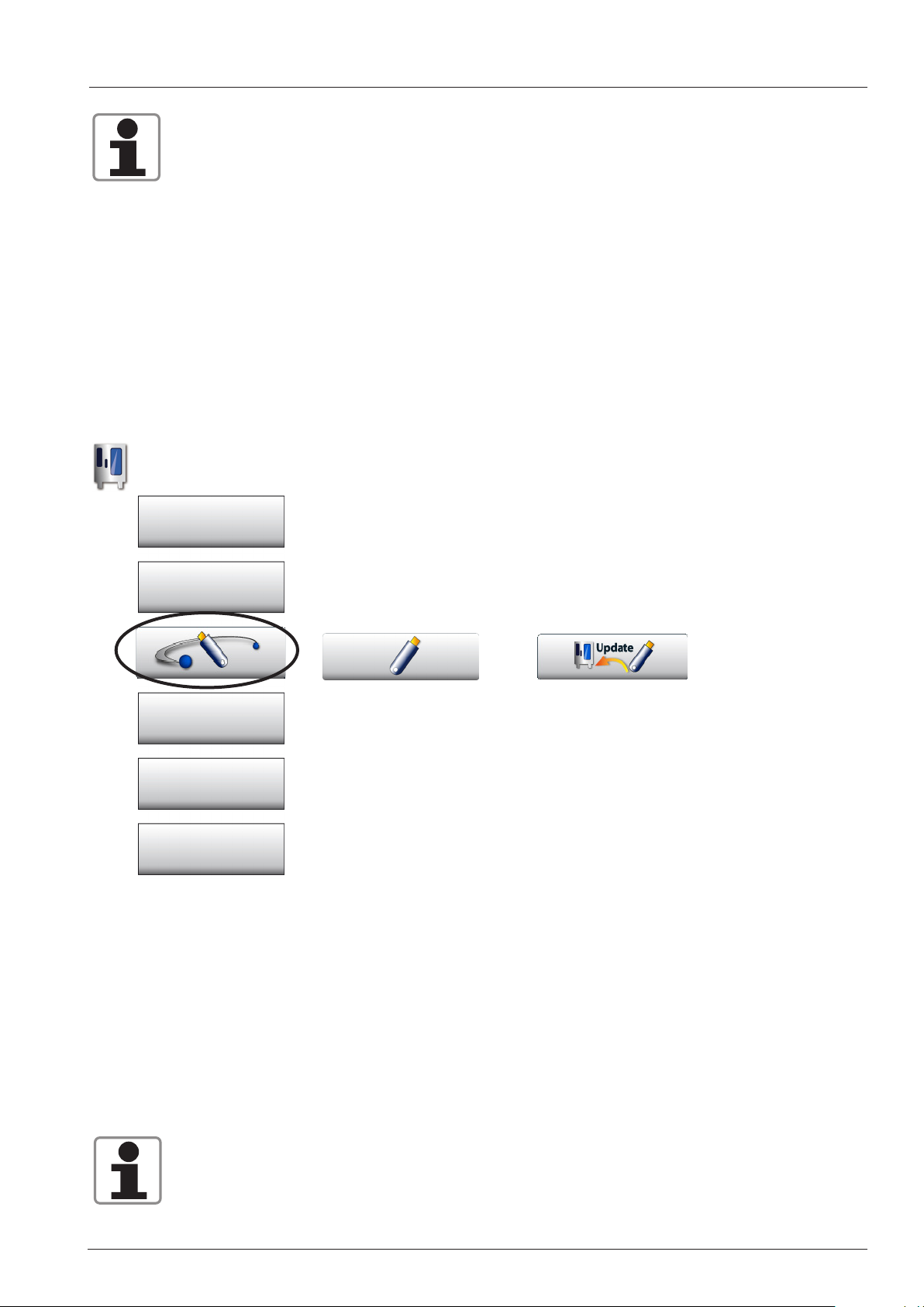
SCC Software update
Only use the Original Rational USB Stick for Software update of SCC_WE units.
(Note: Most of the standard USB sticks can not be used for software update.)
The Rational USB Stick can be ordered with service part number: 87.01.084.
Software can only be updated to a higher version.
NOTE: The duration of a complete software update can last up to 10 miunutes!!
Please follow below instructions!
Software update can be done by the customer as follows::
Connect the USB stick with the USB interface at the bottom left hand corner of the control panel.
Funktionstaste
Settings
HACCP
Service
Display configuration
For standard update proceed as follows:
1. Switch unit on
2. Wait unitl the user interface is shown on the display.
3. Connect the USB stick with the latest software version with the USB interface at the bottom
left hand corner of the control panel.
Press the key Communication, USB and update.
4. Switch unit off and on again.
The unit will display „Update“
Only remove the USB stick after the display has changed again to the standard SCC display.
Please always make sure your customer has the latest software version on his appliance.
- 57 - V02 en, SCC_WE
Page 58
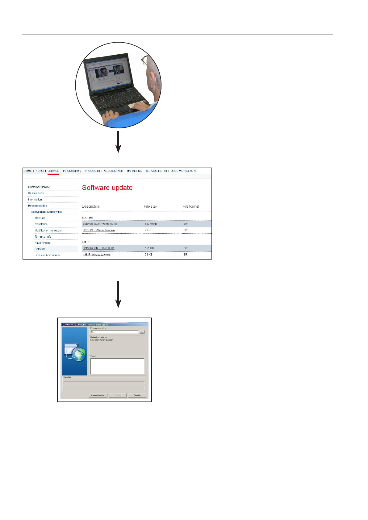
SCC Software update
with Login
Service Web Site: https://portal.rational-online.com
Internet connection
Download Software.zip file
Download SCC Webupdate .exe
Unzip downloaded Software to whiteRATIONAL-USB stick.
Stick format: FAT32
The stick shall not contain any other
data!
Whe new software becomes available
software can be updated on
RATIONAL USB by using
UPDATE SCC_WE.exe file without
login to service web site.
V02 en, SCC_WE - 58 -
Update unit with RATIONAL USB stick.
Page 59

- 59 - V02 en, SCC_WE
Page 60
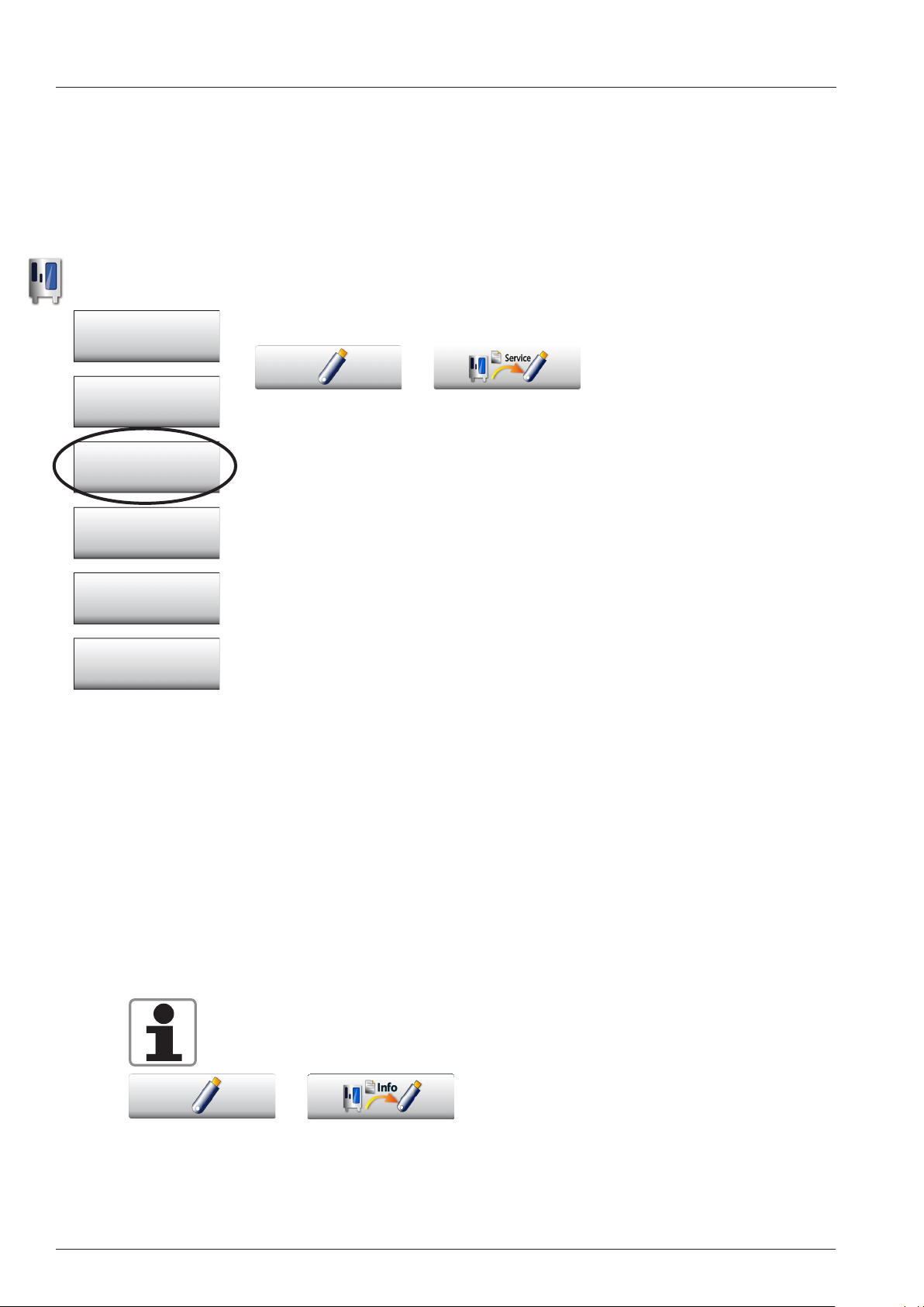
Download of service data
With this function all actual valid service data of the diagnose program can be downloaded onto a
stick. This can be done during an active process or also if the unit is in standby (unit must be switched
on). To get all data the download should be done during an active process.
The maximum number of download‘s on one SCC is 4 times within one our.
Connect USB Stick to unit interface. If the stick is recognised it will be
shown as a blue stick symbol right of the download key.
Funktionstaste
Touch key. During the Download-process the colour of the stick chan-
Einstellungen
HACCP
Kommunikation
Service
Display Konfigurator
ges from blue to red and on the key in the symbol running lines are
visible.
The following data can be found on the stick after connecting it to a PC:
On the stick the folder „log“ can be found.
RAG_xx_yy_SERVICE.txt.
xx: Serial number
yy: Date of Download
The file contains the service datas which are appropriate at the moment
of the download.
The file RAG_xx_yy_SERVICE.txt is partitioned into the following block‘s:
- Common Information
- Basic settings
- Diagnostic Real time data
- Diagnostic-Service History-SCC
- Diagnostic-Service History-Gas
- Diagnostic-Running times
In case your service call is subject to an unknown error and / or the error is sub ject to application problems please always download also the HACCP data!
With the INFO download key complex unit data can be downloaded. These data can only be
evaluated by Rational. The data time range for the download can be selected.
V02 en, SCC_WE - 60 -
Page 61

Download of unit service data
Common Information
------------------
Date and Time.................: 20120515092835
Startup Date and Time.........: undef
Unit type.....................: SCC_62
Energy type...................: E
Unit Serial number............: E62SH12022208034
Software version..............: SCC-05-00-10
Script version................:
SW-update Date and Time.......: undef
CPU-Board Revision............: 0506
CPU-Board Serial number.......: 25233859
CPU-Board Manufacturing date..: 2011-05-19 17:57:58
Burner Control 0 SW-version...:
Burner Control 1 SW-version...:
Language......................: german
Basic Settings
--------------
Drain Valve time0......................................: 8.7 s
Drain Valve time1......................................: 26.1 s
Gas type...............................................: 0
.......................................................:
Diagnostic-Real Time Data-Sensors act max lim Time Stamp dim
-------------------------------------------------------------------------------
Cabinet B1.............................: 26.46 307.85 350 C
Quenching B2...........................: 21.40 95.18 300 C
.......................................:
Temperature PCB........................: 35.34 81.11 80 20120514130736 C
RAG_E62SH12022208034_20120515092833_service
Diagnostic-Real Time Data-Clima Status Dry Wet Combi dim__
-------------------------------------------------------------------------------
Clima Status 1-L.......................: 50066444.6882813.0194368.20 Pa
Clima Status 1-R.......................: 50063631.5785711.5992154.87 Pa
.......................................:
Clima Flap Y5..........................: CLOSE
Clima Output P1........................: 0.00 V
Clima Humidity.........................: 4.00 %
Diagnostic-Water, CJ/Care Motor/Switch Status Status Status dim__
-----------------------------------------------------------------------
Filling solenoid Y1....................: OFF
Volume Steam Generator (Norm Fill Calc): 5.48 5.57 4.38 l
CleanJet Pump M6........................: OFF
Door Contact S3........................: OFF
.......................................:
Diagnostic-Service History-SCC First time Quantity Last time
-------------------------------------------------------------------------------
Service 10.............................: 20111210215318 5 20120418135651
Service 34.............................: 20111213084631 5 20120423131943
.......................................:
Diagnostic-Service History-Gas Top-Box First time Quantity Last time
-------------------------------------------------------------------------------
14.....................................: 20120210145254 3 20120516135457
Diagnostic-Running Times-Components Value dim__
---------------------------------------------------------
Door Opening S3........................: 585
Ball Valve Openings S12................: 1381
.......................................:
Diagnostic-Running Times-Modes Value dim__
---------------------------------------------------------
Hot Air Mode...........................: 192 h
- 61 - V02 en, SCC_WE
Page 62

Download of gas error data
Gas Error Logger Burner Control 0
Indication of the last 14 gas-failures, generated by ignition box top)
Gas Error Logger Burner Control 1
Indication of the last 14 gas-failures,
Indication of ignition box error messages (1-32 is shown to the operator as „Reset“):
1 Hot air or Steam no gas, gas valve or electrode defective
14 Hot air gas valve control, change ignition box
19 Hot air no ame because ame current is too low
check burner setting, ame current, ignition cable and plug
20 Hot air wrong or no rpm signal from gas blower
check gas blower, power supply gas blower and control harness
of gas blower
22 Hot air no ame after 5 ignition sequences
no gas, gas valve or electrode defective
24 Steam gas valve control, change ignition box
29 Steam no ame because ame current is too low
check burner setting, ame current, ignition cable and plug
30 Steam wrong or no rpm signal from gas blower
check gas blower, power supply gas blower and control harness
of gas blower
32 Steam no ame after 5 ignition sequences
no gas, gas valve or electrode defective
generated by ignition box
bottom)
Possible failure in case of „Service 32“
33, 36 Change ignition box
35 Check frequency of main
38 CPU does not send any or correct rpm signal to ignition box; Switch unit off and
on or run repair program for SD Card (SCC_WE) or EEPROM (CM_P)
39 Hot air Check burner setting, ignition electrode and distance,
and ame current
40 Hot air Check ignition cable
42 Steam Check burner setting, ignition electrode and distance,
and ame current
43 Steam Check ignition cable
Is shown on display „Change polarity“
34 Change polarity of mains
All other numbers (2-14, 21, 23, 25-28, 31): change ignition box
V02 en, SCC_WE - 62 -
Page 63

- 63 - V02 en, SCC_WE
Page 64
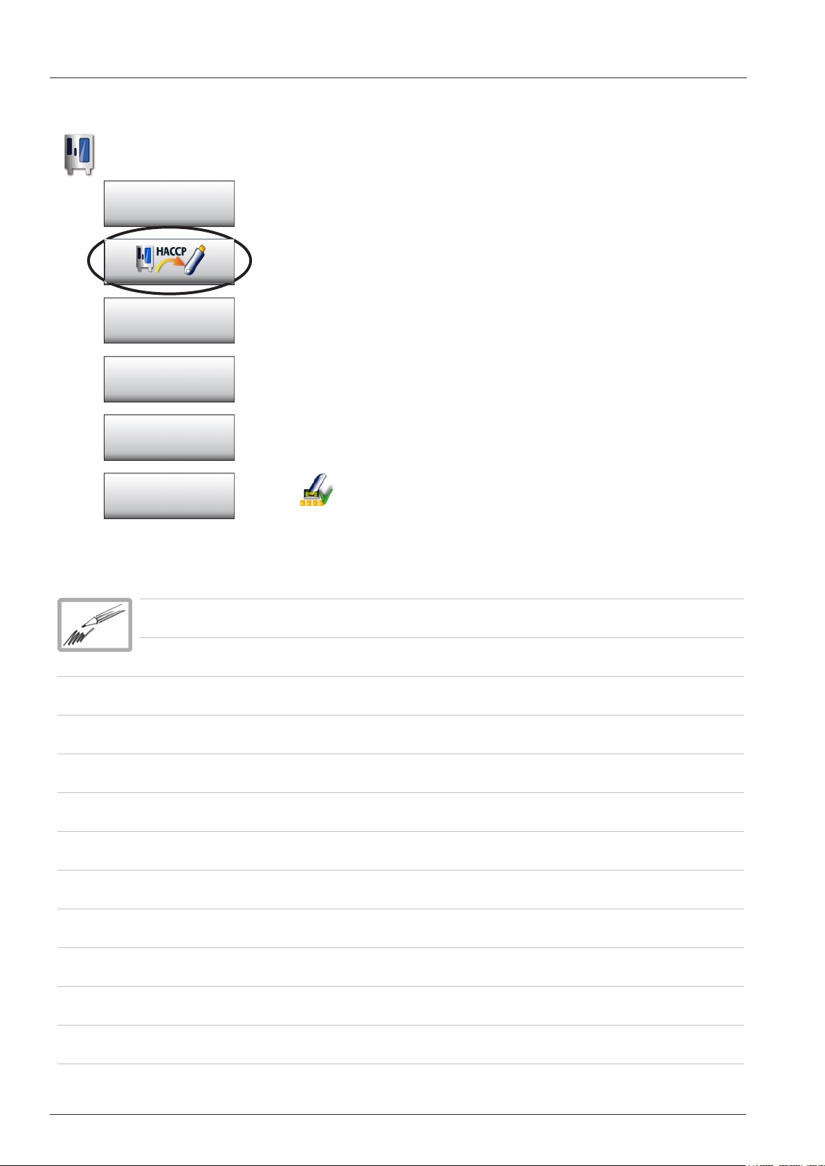
Download of HACCP Data
Function key
Basic Settings
Comunication
Service
Display configurator
HACCP Data will be available for approximately 10 days when the
unit is used for 16 hours daily.
Should the daily usage be less than that the storage time will be
extended accordingly.
Normally HACCP data can be downloaded onto any commercial
USB memory stick.
- connect USB stick to unit interface
- select desired download period
- press download button
When the green tick mark shows on the writing symbol the download is finished.
V02 en, SCC_WE - 64 -
Page 65

Format of HACCP Data
HACCP-Data are shown in the following format:
*** H A C C P ***
;
; Ch-nr. >>210<< = batch number
(number of stored cooking processes)
; Type >>SCC_61<< = unit type
; Serial nr.>>E61SH11092534567<< = Serial number of the unit
; Version >>SCC - (s/o/C)<< = Software version of the unit
(„C“ indicates, delay of CleanJet request is activated
Only chain units:
„s“ or „o“ shows unit ran on
(s) Supervisor- or (o) Operator mode.)
; Time >>2011.09.20 12:27:26<< =
; Progr. >>Roast<< = Program name
(manual mode was used, if „>><<“ appears )
; #1 : Gartemp. / cabinet temp.
; #2 : Kerntemp. Soll / core temp. target
; #3 : Kerntemp / core temp.
; #4 : Zeit (Std:Min:Sek) / time (h:min:sec)
; #5 : Temp. Einheit / temp. unit
; #6 : Energie Opt. / energy opt.
; #7 : Energie 1/2 / energy 1/2
; #1 #2 #3 #4 #5 #6 #7
; Mode HOT AIR 000:00:00 = used cooking mode
29 - 32 000:00:00 C - ; Mode COMBI 000:00:04
29 - 32 000:00:04 C - ; Mode HOT AIR 000:00:07
29 - 32 000:00:07 C - 29 - 32 000:00:11 C - ; end = End of cooking process
Starting date and time of the cooking process
B) Additional indications:
Progr. >>SCC - Universal Roast<< = Indication of selected SCC process
Progr. >>SCC - ~ pork<< = Copied SCC process with new name
Door opened or Door closed = during cooking process
Start (power failed) = Power failure longer than 15 minutes
end (HOME) = Process terminated with Home key
end (RETURN) = Process terminated with arrow back key
end (ERROR) = Process terminated because of error
start ELC = ELC Process started
restart (POWER) = restart after switching off or power fail
end = Process finished
- 65 - V02 en, SCC_WE
Page 66
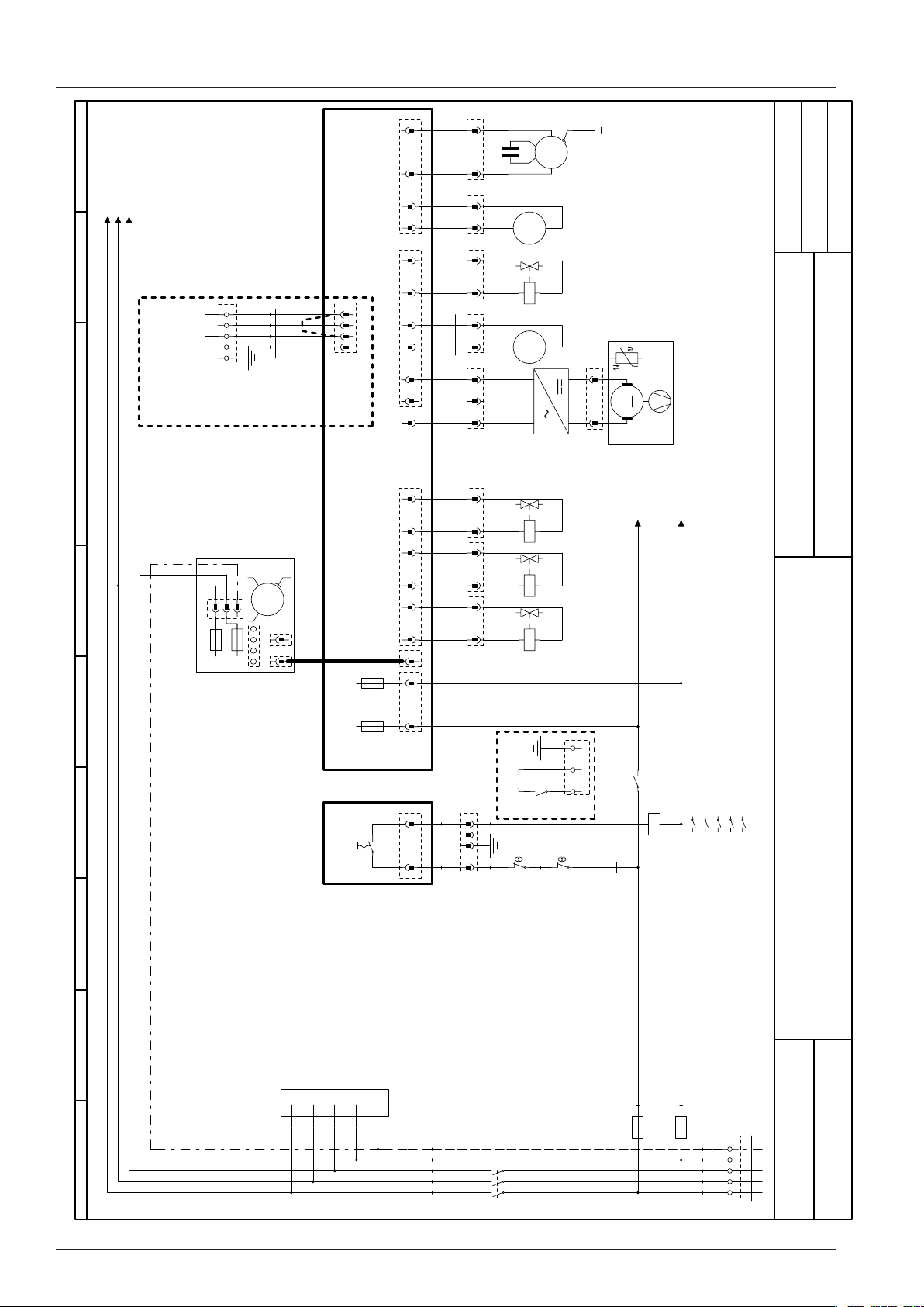
Circuit diagram 101 Power 3NAC 400-415V
0123456789
33
44
K1:1 / 2.00
K1:3 / 2.00
K1:5 / 2.00
44
33
22
11
X20:3 Gerät EIN
X20:4 Heizungsanforderung
ohne Option
Brücke 2-4
w/o option
Link 2-4
Option
Sicotronic system
3
2
1
N
PE
X0:PE
X0:N
X0:1 Eingang Sicotronic
X0:2 Gerät EIN
X0:3 Heizungsanforderung
X.0
3
2
1
BU
.
W32
X20:1 Nullleiter
X20:2 Eingang Sicotronic
22
11
X18
66
11
55
22
X20
33
44
X75
N
22
BU
11
XM6
WH
22
BU
11
XM4
WH
22
BU
11
XY4
OG
11
BU
22
XM12
BN
W30
11
GY
22
33
XG1
BU
1
SCHD
.
C1
~
M
PE
~
M
M6
M4
A1
A2
Erstellt von
Created by
Datum
05.10.2011
Date
Blatt
Page
Y4
~
M
M12
L1
N
2
G1
22
-
M
11
+
M5
XM5
SCC WE 101E
XM1
M1-F1
M1
33
66
22
55
33
22
M1-F2
6,3A
~
11
M
6,3A
BUS
A2
S1
11
44
X19
22
X21
X7.2
11
22
11
2AT
A2-F2
2AT
A2-F1
A1
22
BU
XY3
11
A1
WH
22
BU
XY2
11
WH
22
BU
XY1
11
WH
Y3
Y2
A2
A1
A2
A1
A2
Y1
BU
BN
2
.
PEX0 1
N/O
K1
Option Pot.-freier Kontakt
Option pot.-free contact
22
BKRD
33 44
XS1
11
1
2F41
BNGYRDBN
2
F3
W17
K1
K1:13 / 3.00
K1:A2 / 3.00
1314
N/O
.00
.00
.00
.03
.03
A1
A2
12
34
56
K1
13 14
3NAC400 V 50/60 Hz
MODUL 1
Leistung/Power
W31
Z1
L1
L2
L3
N
PE
YE/GNYE/GN
BUBU
VTVT
OGOG
BKBK
0
V02 en, SCC_WE - 66 -
1Version
BN
BU
76-00441
F1 6,3A
F2 6,3A
5
6
3
4
1
2
N/O
K1
PE X0
N
L3
L2
L1
W0
Page 67
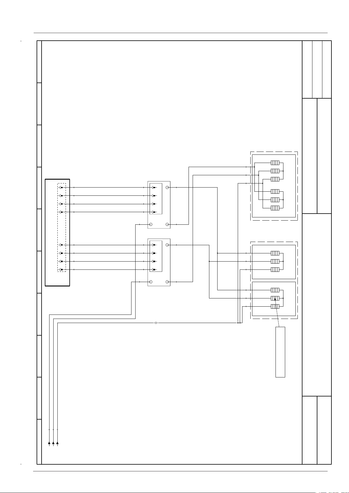
Circuit diagram 101 Heating 3NAC 400-415V
0123456789
A2
D2+
D2-
HL1+
HL1-
D1+
D1-
HL2+
HL2-
55
GYGYOG
66
OGOG
77
RDRD
88
BNBN
11
WHWHBK
22
OGOGOG
33
RDRDBK
44
BNBNVT
X24
11
A2
22
(D2)
A- A+
33
XV2
44
B- B+
XV1
A1/B1
11
22
33
44
A1/B1
L3X00
(HL1)
B2
A2
(D1)
A- A+
B- B+
(HL2)
B2
OGOG
V2
BKBK
V1
2
SCHD
05.10.2011
Erstellt von
Created by
Datum
Date
Blatt
Page
11
OG
BK
VT
12
7
8
SCC WE 101E
3NAC400 V 50/60 Hz
3
4
9
10
HL1/HL2
5
1
18kW(6x3kW)
6
2
R4
6
5
4
3
1
D1/D2
9kW(3x3kW)
2
R2
6
OG
BK
VT
5
4
3
1
D1/D2
9kW(3x3kW)
2
R1
MODUL 2
Heizung/Heating
Therm ocouple steam generator
Therm oelement Dampfgenerator
VT
BK
OG
1.08 / K1:1
1.08 / K1:3
1.08 / K1:5
0
- 67 - V02 en, SCC_WE
1Version
76-00441
Page 68
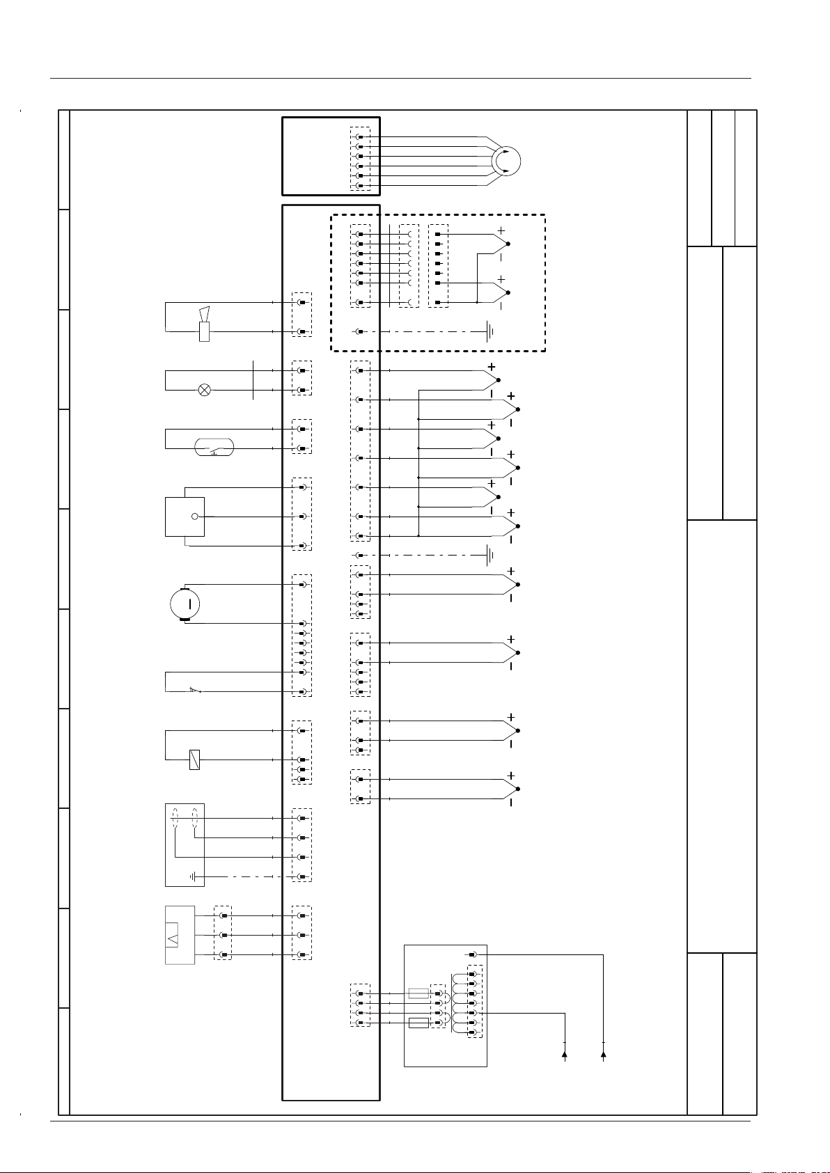
Circuit diagram 101 Sensor
9876543210
A1
BK
BNYE/GN
BUYE
BN
W11
WH
WH
WH
WH
GY
WH
WH
YE/GN
S11
M7
S2
T2
H1
S3
IN
GND
HALL
Signal
-+
M
S12
Y5
3
66
SCHD
05.10.2011
22 33 44 55
11
X10
1
11
22
.
33
.
44
.
55
.
66
.
22
11
X8
22
11
X13
22
11
X27
33
22
11
X15
88
66 77
44 55
33
22
11
X25
44
33
22
11
X11
11
22
33
44
X12
.
77
Option Thermoelement Sousvide
Option Thermocouple Sousvide
.
X2
W23
11
.
22
OG
.
33
GN
.
44
BU
.
55
BN
.
66
BK
.
77
X2
X6
X5
X4
X3
WH
.
11
GN
22
WH
44 33
11
GN
22
WH
33
44
55
11
GN
22
WH
33
11
GN
22
WH
1
2
2
3
3
4
4
5
5
6
6
7
7
X2.0
X2.1
YE/GN
S6
B7
B3
B5
B4
B2
B1
Erstellt von
Created by
Datum
Date
SCC WE 101E
MODUL 3
Sensoren/Sensors
Blatt
3NAC400 V 50/60 Hz
Page
33
P
P1
22
SignalIN GND
11
XP1
33
GY
22
GY
11
GY
X1
T1-F2
44
33
22
11
X14
5AT
WH
WH
GY
GY
2AT
T1-F1
T1
A2
0
V02 en, SCC_WE - 68 -
N
0
.
200V
.
208V
1
3
.
.
220V
2
4
.
18V
230V
5
3
.
.
240V
4
6
.
11,5V
250V
7 2 1
SXT1
PXT1
BN
BU
1.06 / K1:13
1.06 / K1:A2
1Version
76-00441
Page 69
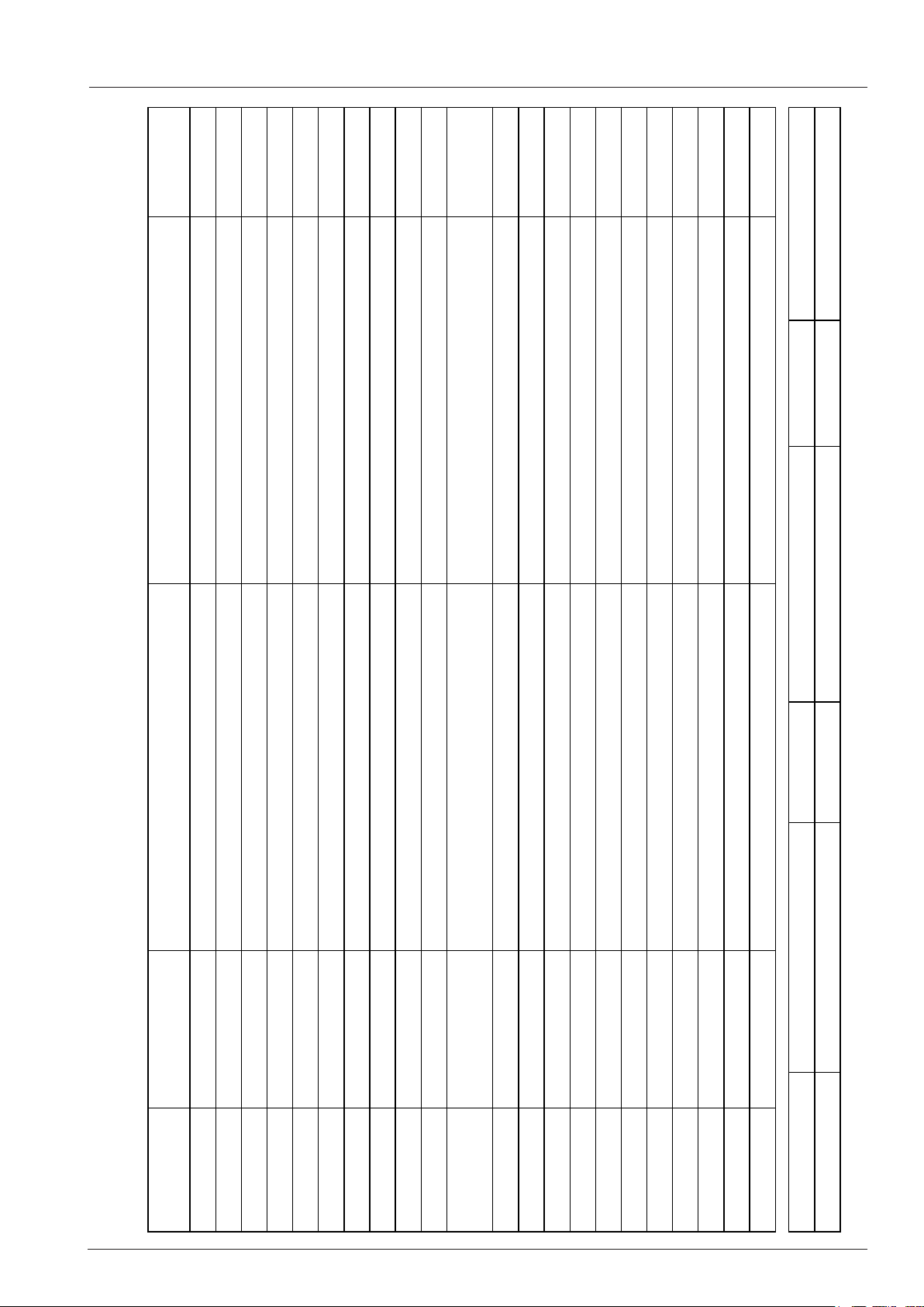
Circuit diagram Bill of material
Module
Modul
Modul 1
Item description
Artikelbezeichnung
Safety thermostat steam generator Gas: 157°C/
314°F Elec.: 183°C/360°F
Seite 1 von 2
F Elek.:183°C/360°F
Artikelnr.
Item number
Änderungsdatum 30.08.2011 Name SCC WE 101E Dokument-Nr. 78-00722
Positionsliste
Bill of material
Name
Name
-A1 42.00.081 Interface Platine Interface PCB Modul 1
-A2 42.00.160 CPU SCC WE CPU SCC WE Modul 1
-A2-F1/F2 3019.0120 Sicherung A2 - 2AT Fuse A2 - 2AT Modul 1
-A2-F3 3019.0312 Sicherung A2 - 8AT Fuse A2 - 8AT Modul 3
-B1 40.04.096 Thermoelement Garraum Thermocouple interior cabinet Modul 3
-B2 54.01.148 Thermoelement Ablöschung Thermocouple quenching Modul 3
-B3 40.01.604 Thermoelement Kerntemperatur Thermocouple core sensor Modul 3
-B4 40.00.290 Thermoelement Feuchte Thermocouple humidity Modul 3
-B5 40.04.106 Thermoelement Dampfgenerator Thermocouple steam generator Modul 3
-F1/F2 4001.0224 Steuersicherung Control fuse Modul 1
-F3 40.01.329 Sicherheitstemperaturbegrenzer Gas:157°C/314°
-F4 40.01.482 Sicherheitstemperaturbegrenzer 360°C/680°F Safety thermostat interior cabinet 360°C/680°F Modul 1
-G1 40.03.257 Gleichrichter Kühllüfter DC converter cooling fan Modul 1
-H1 3024.0201 Garraumbeleuchtung Interior cabinet light Modul 3
-K1 40.03.696 Hauptschütz Main contactor Modul 1
-M1 40.03.378 Lüftermotor Fan motor Modul 1
-M12 56.00.451 Pumpe Pflegemittel Care pump Modul 1
-M4 44.00.207 SC-Pumpe SC-pump Modul 1
-M5 40.03.428 Kühllüfter Cooling fan Modul 1
-M6 56.00.185 CleanJet Pumpe SCC WE CleanJet pump SCC WE Modul 1
-M7 54.00.357 Kugelhahn Ablauf Drain valve Modul 3
-P1 3017.1011 Differenzdrucksensor Differential pressure sensor Modul 3
Erzeuger ADT Spannung 3NAC400 V 50/60 Hz Version 1
- 69 - V02 en, SCC_WE
Page 70
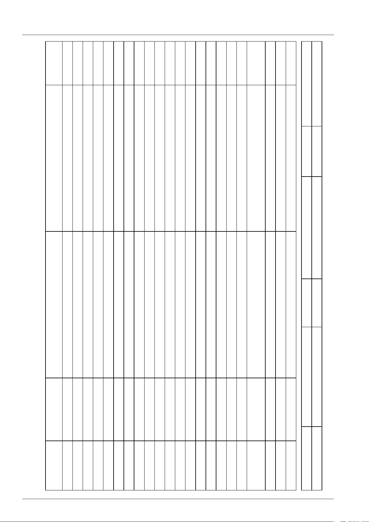
Circuit diagram Bill of material
Module
Modul
Modul 1
Item description
Artikelbezeichnung
Y1: Solenoid valve filling / SCC WE Y3:
moistening / Y4: care
Seite 2 von 2
Beschwadung / Y4: Pflegemittel
Artikelnr.
Item number
Name
Name
-R1 44.01.333 Dampfheizkörper Heating element steam Modul 2
-R2 44.01.337 Dampfheizkörper Heating element steam Modul 2
-R4 40.03.294 Heißluftheizkörper Heating element hot air Modul 2
-S1 TEXT Ein/Aus Schalter ON/OFF switch Modul 1
-S11 50.01.523 CDS-Sensor CDS-sensor Modul 3
-S2 44.01.407 Niveauelektrode Water level electrode Modul 3
-S3 40.00.335 Türkontaktschalter Door contact switch Modul 3
-S6 40.00.404 Zentrales Einstellrad Central dial Modul 3
-T1 40.03.348 Steuertrafo Control transformer Modul 3
-T1-F1 3019.0120 Sicherung Steuertrafo T1 2AT Fuse control transformer T1 2AT Modul 3
-T1-F2 3019.0126 Sicherung Steuertrafo T1 5AT Fuse control transformer T1 5AT Modul 3
Positionsliste
Bill of material
-T2 40.04.034 SCC WE: Lautsprecher / CMP: Alarmsummer SCC WE: Speaker / CMP: Buzzer Modul 3
V02 en, SCC_WE - 70 -
-V1-V12 40.01.589 Leistungshalbleiter Solid state relais Modul 2
-W0 8801.0136 Anschlusskabel Cable: power supply Modul 1
-W11 40.03.531 Kabel: Garraumbeleuchtung Cable: interior cabinet light Modul 3
-W17 40.03.446 Kabel: Steuerstamm Cable: control harness Modul 1
-W30 40.02.965 Kabel: Adapterkabel Pumpe Pflegemittel 61-102 Cable: adapter care pump 61-102 Modul 1
-W31 40.03.467 Kabel: Ein/Aus Schalter Cable: ON/OFF switch Modul 1
Änderungsdatum 30.08.2011 Name SCC WE 101E Dokument-Nr. 78-00722
-Y1/Y3/Y4 50.01.050 Y1: Magnetventil Füllen / SCC WE Y3:
-Y2 50.01.146 Magnetventil Ablöschung Solenoid valve quenching Modul 1
-Y5 22.00.725 Klimaventil Clima valve Modul 3
-Z1 40.02.424 Entstörfilter/Varistor Electronic noise filter Modul 1
Erzeuger ADT Spannung 3NAC400 V 50/60 Hz Version 1
Page 71
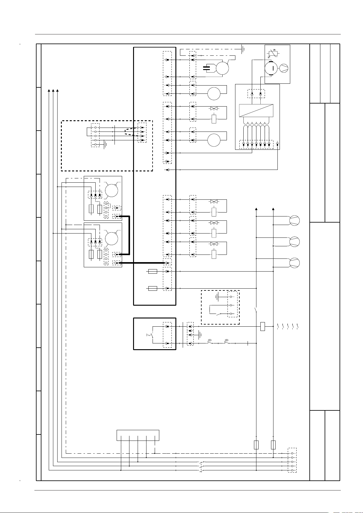
0123456789
Circuit diagram 202 Power 3NAC 400-415V
33
44
K1:1 / 2.00
K1:3 / 2.00
K1:5 / 2.00
44
33
22
11
X20:3 Gerät EIN
X20:4 Heizungsanforderung
ohne Option
Brücke 2-4
w/o option
Link 2-4
BUS
BUS
Option
Sicotronic system
3
2
1
N
PE
X0:PE
X0:N
X0:1 Eingang Sicotronic
X0:2 Gerät EIN
X0:3 Heizungsanforderung
33
22
XM2
M2-F1
6,3A
M2
33
22
XM1
M1-F1
6,3A
M1
X.0
M2-F2
M1-F2
3
2
1
BU
.
W32
X20:1 Nullleiter
X20:2 Eingang Sicotronic
~
M
11
6,3A
~
11
M
6,3A
A2
S1
22
11
X18
66
11
55
22
X20
44 33
X75
N
33
66
22
55
11
44
X19
22
X21
X7.2
11
22
11
2AT
A2-F2
2AT
A2-F1
A1
55
22
BU
11
XM6
WH
22
BU
11
XM4
WH
22
BU
11
XY4
OG
11
BU
22
XM12
BN
GY
BU
22
BU
XY3
11
WH
22
BU
XY2
11
WH
22
BU
XY1
11
WH
BU
BN
22
BKRD
33 44
XS1
11
BNGYRDBN
W31
1
YE/GN
PE
SCHD
05.10.2011
.
C1
~
M
M6
M
M5
22
M4
Y4
M12
~
M
A1
A2
T4
~
M
PXT4
SXT4
12V
-
230V
240V
250V
7766554433
220V
11
0V
208V
200V
22
Erstellt von
Created by
Datum
Date
Blatt
Page
~
0V
11
N
SCC WE 202E
3NAC400 V 50/60 Hz
K1:13 / 3.00
A1
A2
Y3
A1
A2
Y2
A1
A2
Y1
PE
.
K1
N/O
K1
Option Pot.-freier Kontakt
Option pot.-free contact
1
2F41
W17
2
F3
K1:A2 / 3.00
~
M
1
A2 A1
M14
~
M
1
A2 A1
M13
~
M
1
A2 A1
M11
1314
N/O
.00
.00
.00
.03
A1
A2
12
K1
34
56
13 14
.03
MODUL 1
Leistung/Power
Z1
L1
L2
L3
N
PE
YE/GNYE/GN
BUBU
VTVT
OGOG
BKBK
5
6
3
4
1
2
N/O
K1
0
F1 6,3A
BN
BU
F2 6,3A
PE X0
N
L3
L2
L1
- 71 - V02 en, SCC_WE
1V ersion
76-00446
Page 72
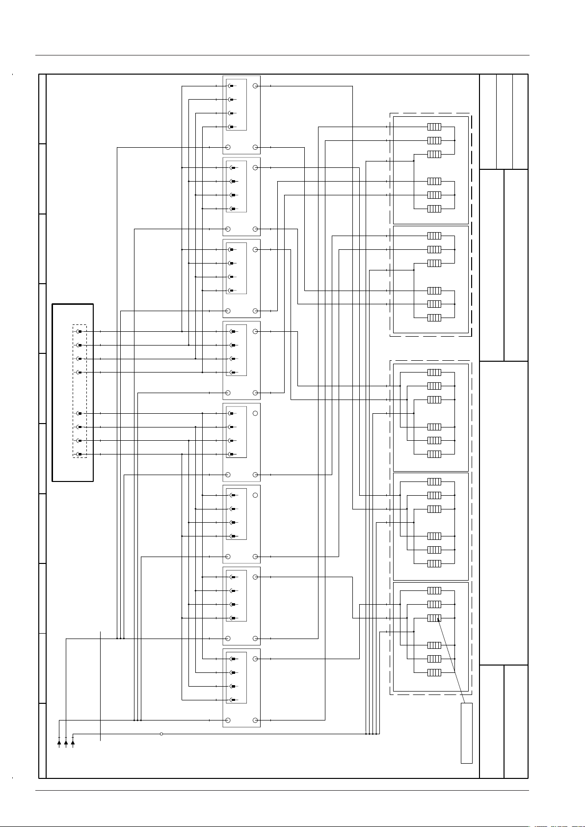
0123456789
Circuit diagram 202 Heating 3NAC 400-415V
11
GYOG
22
OG
33
RD
XV8
44
BNOG
OGGY
V8
GYBK
OGGY
RDBN
XV7
BN
BKBN
V7
11
GYOGBK
22
OG
33
RD
XV6
44
BNGY
OGGY
V6
XV5
BKBN
V5
11
22
33
XV4
44
OGOG
A2
D2+
D2-
HL1+
HL1-
D1+
D1-
HL2+
HL2-
55
GYGYBK
66
OGOG
77
RDRD
88
BNBN
11
WHWHVT
22
OGOG
33
RDRD
44
BNBN
X24
V4
WHBK
OGOG
RDVT
XV3
BN
BKBK
V3
WHOG
OG
RDBK
XV2
BNOG
OGOG
V2
WHBK
OG
RD
XV1
BN
VT
BK
OG
L3X00
W16
1.08 / K1:1
1.08 / K1:3
1.08 / K1:5
BKBK
V1
A1/B1
11
22
33
44
A1/B1
A1/B1
11
22
33
44
A1/B1
A1/B1
11
22
33
44
A1/B1
11
22
33
44
A1/B1
11
22
33
44
A1/B1
2
A2
(D2)
A- A+
11
7
3
unten
9
5
1
11
7
3
oben
9
5
1
8
12
4
unten
6
10
2
8
12
4
mitte
6
10
2
8
12
4
oben
6
10
2
down
top
down
middle
top
12
8
4
10
6
2
12
8
4
10
6
2
7
11
3
D2
5
9
1
7
11
3
D2
5
9
1
7
11
3
D1
5
9
1
B- B+
(HL1)
BK
B2
A2
VT
(D2)
A- A+
B- B+
(HL1)
B2
R5
OG
A2
(D2)
A- A+
B- B+
(HL1)
VT
BN
B2
A2
(D2)
A- A+
B- B+
(HL1)
B2
R4
BK
OG
A2
(D1)
A- A+
B- B+
(HL2)
R3
B2
A2
(D1)
A- A+
B- B+
(HL2)
B2
A2
(D1)
A- A+
B- B+
(HL2)
R2
VT
B2
A2
(D1)
A- A+
HL2
33kW(6x5,5kW)
HL1
HL2
33kW(6x5,5kW)
HL1
SCHD
05.10.2011
Erstellt von
Created by
Datum
Date
Blatt
Page
.
.
SCC WE 202E
3NAC400 V 50/60 Hz
18kW(6x3kW)
.
18kW(6x3kW)
18kW(6x3kW)
MODUL 2
Heizung/Heating
.
1V ersion
R1
B- B+
(HL2)
B2
Thermoelement Dampfgenerator
0
76-00446
Thermocouple steam generator
V02 en, SCC_WE - 72 -
Page 73
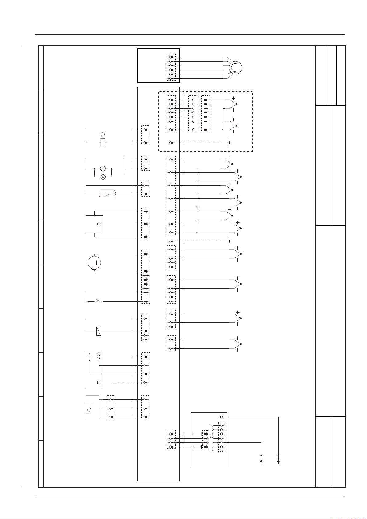
Circuit diagram 202 Sensor
9876543210
BK
BNYE/GN
BUYE
BN
W11
WH
WH
WH
WH
GY
WH
WH
YE/GN
S11
S2
M7
T2
H1
H2
S3
IN
GND
HALL
Signal
-+
M
S12
Y5
A1
3
66
SCHD
05.10.2011
22 33 44 55
11
X10
1
11
22
.
33
.
44
.
55
.
66
.
22
11
X8
22
11
X13
22
11
X27
33
22
11
X15
88
77
66
55
44
33
22
11
X25
44
33
22
11
X11
11
22
33
44
X12
.
77
Option Thermoelement Sousvide
Option Thermocouple Sousvide
.
X2
W23
11
.
22
OG
.
33
GN
.
44
BU
.
55
BN
.
66
BK
.
77
WH
.
X2
11
GN
22
WH
33
44
X6
11
GN
22
WH
33
44
55
X5
11
GN
22
WH
33
X4
11
GN
22
X3
WH
1
2
2
3
3
4
4
5
5
6
6
7
7
X2.0
X2.1
YE/GN
S6
B7
B3
B5
B4
B2
B1
Erstellt von
Created by
Datum
Date
SCC WE 202E
MODUL 3
Sensoren/Sensors
Blatt
3NAC400 V 50/60 Hz
Page
33
P
P1
22
SignalIN GND
11
XP1
33
GY
22
GY
11
GY
X1
T1-F2
44
33
22
11
X14
5AT
WH
WH
GY
GY
2AT
T1-F1
N
0
1
.
200V
2
.
208V
1
3
.
.
220V
2
4
.
18V
230V
5
3
.
.
240V
4
6
.
11,5V
250V
7
SXT1
PXT1
BU
BN
1Ver sion
76-00446
T1
A2
1.06 / K1:13
0
1.06 / K1:A2
- 73 - V02 en, SCC_WE
Page 74
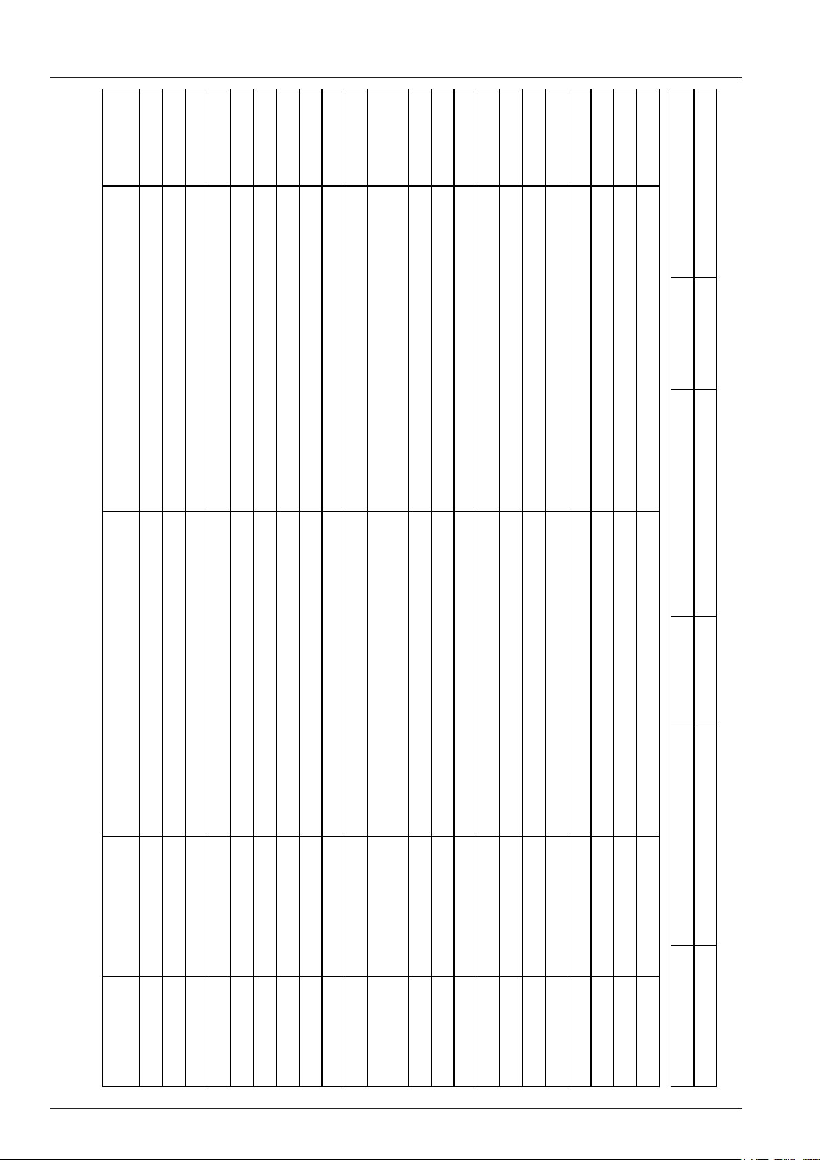
Circuit diagram Bill of material
Module
Modul
Modul 1
Item description
Artikelbezeichnung
Safety thermostat steam generator Gas: 157°C/
314°F Elec.: 183°C/360°F
Seite 1 von 3
F Elek.:183°C/360°F
Artikelnr.
Item number
Name
Name
-A1 42.00.081 Interface Platine Interface PCB Modul 1
-A2 42.00.160 CPU SCC WE CPU SCC WE Modul 1
-A2-F1/F2 3019.0120 Sicherung A2 - 2AT Fuse A2 - 2AT Modul 1
-A2-F3 3019.0312 Sicherung A2 - 8AT Fuse A2 - 8AT Modul 3
-B1 40.03.528 Thermoelement Garraum Thermocouple interior cabinet Modul 3
-B2 54.01.254 Thermoelement Ablöschung Thermocouple quenching Modul 3
-B3 40.02.101 Thermoelement Kerntemperatur Thermocouple core sensor Modul 3
-B4 40.00.399 Thermoelement Feuchte Thermocouple humidity Modul 3
-B5 40.04.107 Thermoelement Dampfgenerator Thermocouple steam generator Modul 3
-F1/F2 4001.0224 Steuersicherung Control fuse Modul 1
Positionsliste
Bill of material
-F3 40.01.329 Sicherheitstemperaturbegrenzer Gas:157°C/314°
V02 en, SCC_WE - 74 -
-F4 40.01.482 Sicherheitstemperaturbegrenzer 360°C/680°F Safety thermostat interior cabinet 360°C/680°F Modul 1
-H1 3024.0201 Garraumbeleuchtung Interior cabinet light Modul 3
-H2 3024.0201 Garraumbeleuchtung Interior cabinet light Modul 3
-K1 40.03.666 Hauptschütz Main contactor Modul 1
-M1 40.03.513 Lüftermotor Fan motor Modul 1
-M11 40.03.425 Kühllüfter Cooling fan Modul 1
-M12 56.00.460 Pumpe Pflegemittel Care pump Modul 1
-M13 40.03.425 Kühllüfter Cooling fan Modul 1
-M14 40.03.425 Kühllüfter Cooling fan Modul 1
-M2 40.03.513 Lüftermotor 201/202 (unten) Fan motor 201/202 (bottom) Modul 1
-M4 44.00.207 SC-Pumpe SC-pump Modul 1
Änderungsdatum 30.08.2011 Name SCC WE 202E Dokument-Nr. 78-00725
Erzeuger ADT Spannung 3NAC400 V 50/60 Hz Version 1
Page 75
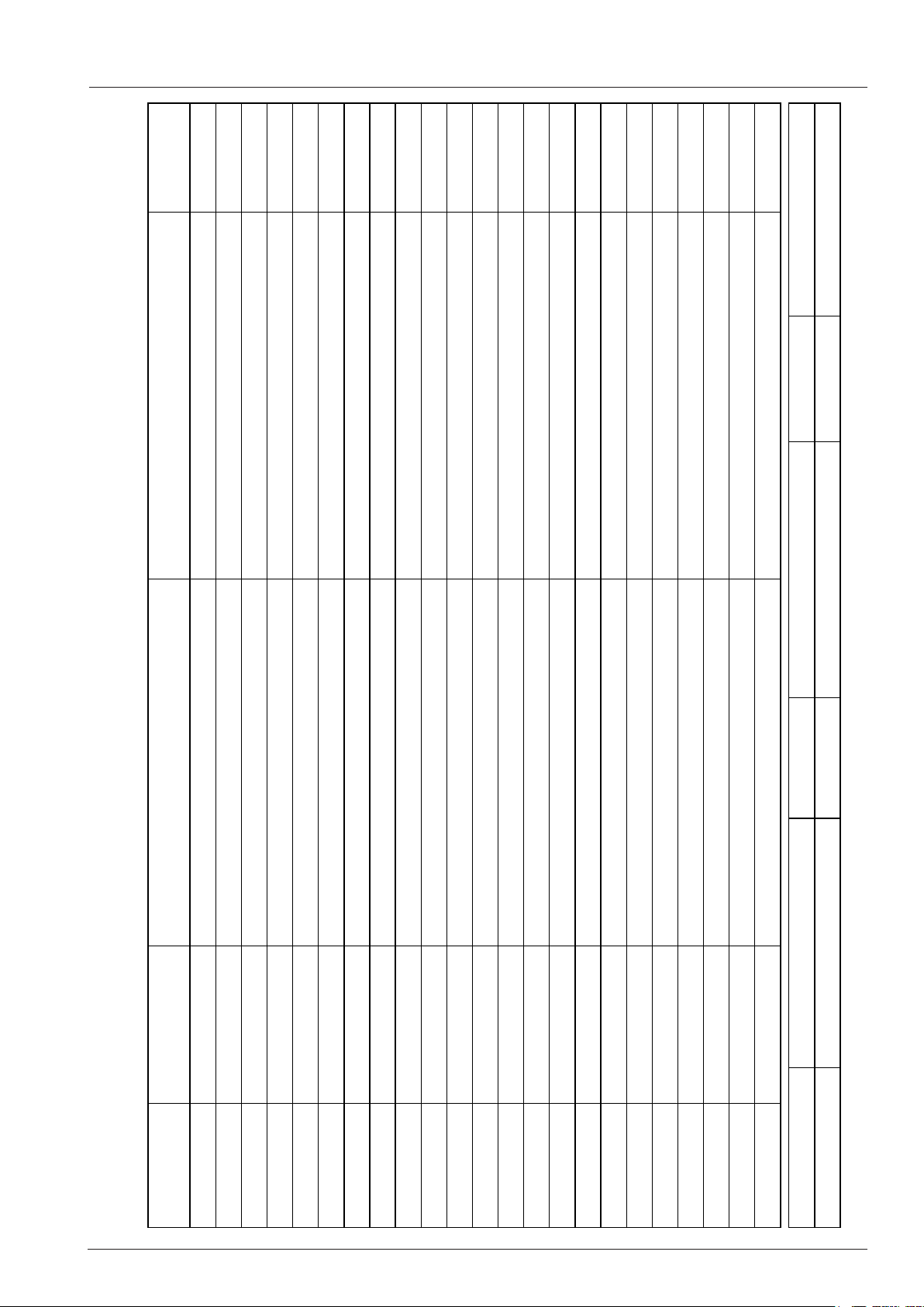
Circuit diagram Bill of material
Module
Modul
Item description
Artikelbezeichnung
Seite 2 von 3
Artikelnr.
Item number
Änderungsdatum 30.08.2011 Name SCC WE 202E Dokument-Nr. 78-00725
Positionsliste
Bill of material
Name
Name
-M5 40.03.948 Kühllüfter Cooling fan Modul 1
-M6 56.00.186 CleanJet Pumpe SCC WE CleanJet pump SCC WE Modul 1
-M7 54.01.291 Kugelhahn Ablauf Drain valve Modul 3
-P1 3017.1011 Differenzdrucksensor Differential pressure sensor Modul 3
-R1 44.01.336 Dampfheizkörper Heating element steam Modul 2
-R2 44.01.340 Dampfheizkörper Heating element steam Modul 2
-R3 44.01.340 Dampfheizkörper Heating element steam Modul 2
-R4 40.03.300 Heißluftheizkörper Heating element hot air Modul 2
-R5 40.03.300 Heißluftheizkörper Heating element hot air Modul 2
-S1 TEXT Ein/Aus Schalter ON/OFF switch Modul 1
-S11 50.01.195 CDS-Sensor CDS-sensor Modul 3
-S2 44.01.408 Niveauelektrode Water level electrode Modul 3
-S3 40.00.454 Türkontaktschalter Door contact switch Modul 3
-S6 40.00.404 Zentrales Einstellrad Central dial Modul 3
-T1 40.03.348 Steuertrafo Control transformer Modul 3
-T1-F1 3019.0120 Sicherung Steuertrafo T1 2AT Fuse control transformer T1 2AT Modul 3
-T1-F2 3019.0126 Sicherung Steuertrafo T1 5AT Fuse control transformer T1 5AT Modul 3
-T2 40.03.989 SCC WE: Lautsprecher / CMP: Alarmsummer SCC WE: Speaker / CMP: Buzzer Modul 3
-T4 40.03.772 Trafo Kühllüfter 201/202 Transformer cooling fan 201/202 Modul 1
-V1-V12 40.01.589 Leistungshalbleiter Solid state relais Modul 2
-W11 40.03.532 Kabel: Garraumbeleuchtung Cable: interior cabinet light Modul 3
-W16 40.03.978 Kabel: Klemmen/Hauptschütz/SSR Cable: terminal/main contactor/SSR Modul 2
-W17 40.03.450 Kabel: Steuerstamm Cable: control harness Modul 1
Erzeuger ADT Spannung 3NAC400 V 50/60 Hz Version 1
- 75 - V02 en, SCC_WE
Page 76

RTS Contact Germany
Fax: +49 (0)8191-327397
e-mail: [email protected]
web: https://portal.rational-online.com
Service Parts:
Fax: +49 (0)8191-327408
e-mail: [email protected]
Chef Line:
Phone: +49 (0)8191-327300
© 2011 Rational Technical Services. All rights reserved.
Please note that any technical information concerning Rational products
must NOT be forwarded to any third party.
80.51.113 - V02 en -SCC - RTS/Sc 02/2012
 Loading...