

Page 1
-1-
Training Manual
Diagnostic and Troubleshooting
SCC Line
SelfCooking Center - Combi Master
Edition 11-2006
Page 2
-2-
Training Manual
Diagnostic and Troubleshooting
SCC Line
Edition 11-2006
General hints:
Isolate the appliance from mains supply
before opening the appliance
When working with chemicals, i.e. aggressive cleaning materials
always wear protective clothing, goggles and gloves!
After maintenance / repair the appliance must be checked for electric safety
in accordance with your national, state and local requirements!
Whenever working on any gas component like:Gas valve, gas blower
and / or changing connected type of gas a detailed
fl ue gas analysis MUST be done using adequate
CO and CO2 measuring equipment!
This shall ONLY be done by trained technicians!
Always check appliance for possible gas leakages!
Part 1: Topic: CM technique Page:
1. CM Overlay
2. CM Principle
3. CM Water level control
4. CM Steam control
5. CM Key code
6. CM PCB
7. CM Main fan Motor
8. CM Sequence of events
9. CM Service level
10. CM Diagnostic
11. CM Running times
12. CM Basic settings
13. CM Function test
14. CM Error history
15. CM Failure code
16. CM Gas principle
17. CM Gas components
18. CM Burner sequence of events
19. CM Gas Conversion
20. CM Gas changing installation altitude
21. CM Gas Flue gas analysis
22. CM Gas adjustment table
23. CM Gas Changing gas blower speed
04
05
06
07
08 - 09
10
11
12 - 16
17
18
19
20 - 21
22 - 23
24
25
26
27
28
29
30
31 - 32
33
34
Page 3

-3-
Part 2: Topic: SCC Technique Page:
1. SCC Overlay
2. SCC Self Cooking Control until software 01-07-12
3. SCC Combi Steamer mode until software 01-07-12
4. SCC Self Cooking Control since software 02-01-01
5. SCC Combi Steamer mode since software 02-01-01
6. SCC Programming, CleanJet
4. SCC Principle
5. SCC Operator PCB; LED code;
6. SCC I/O PCB; LED Code
7. SCC Main fan Motor; LED code
7. SCC Sequence of events (cooking modes)
8. SCC Service level
9. SCC Diagnostic mode overview
10. SCC Diagnostic mode
11. SCC Running times overview
12. SCC Running times
13. SCC Basic settings overview
14. SCC Basic settings
15. SCC Function test overview
16. SCC Function test
17. SCC Overview Service messages / intermittent buzzer code
17. SCC Service messages
18. SCC Calibration
19. SCC Drain valve
20. SCC Gas principle
21. SCC Gas technique
22. SCC Burner sequence of events
23. SCC Gas conversion
24. SCC Gas adjustment of installation altitude
25. SCC Flue gas analysis
26. SCC Gas adjustment table
27. SCC Gas changing gas blower speed
Part 3: Topic: Common topics SCC and CM Page:
1. Software fl ashing SCC
2.
SCC Fault tree „pcb/EEPROM changing; software update“
3. Software fl ashing CM
5. CM Fault tree „Changing pcb/EEPROM, Fault E1“
6.
CM fl ashing via PC
7. Electrical descaling pump
8. Installation Checklist
9. Preventative maintenance list
10. Water Info
Part 4: Fault list SCC and CM
1. Index
2. Fault list SCC
3. Fault list CM
Part 5: Circuit diagram (Training version 3NAC 400V)
SCC - CM Reference sheet
35
36
37
38
39
40
42
44
45
46
48 - 53
54
56
57 - 59
60
61 - 62
64
65 - 67
68
69 - 70
72
73 - 74
76 - 77
78
80
82
83
84
85
86 - 87
88
89
91
92
93 - 94
95
96
98 - 99
100 - 103
104 - 106
108
110
111 - 121
122 - 127
Page 4
-4-
S
C
M
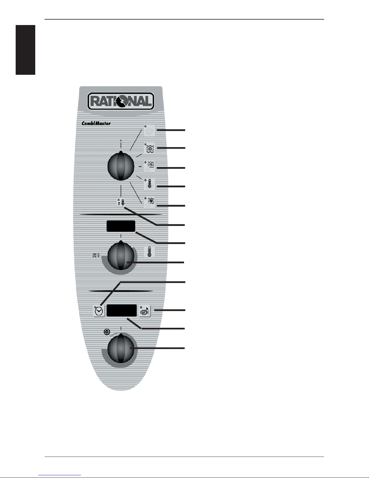
Steam
Hot Air
Combi Steam
Low Temperature Steam
Finishing
Cool Down
Cabinet temperature display
Cabinet temperature setting
Timer
Core temperature
Time - Core temperature display
Time - Core temperature setting
CM Technique from 04 - 2004
Page 5
-5-
S
C
M
B1
B3
F4
M4
Y1
Y2
B2
M1
S2
B5
F3
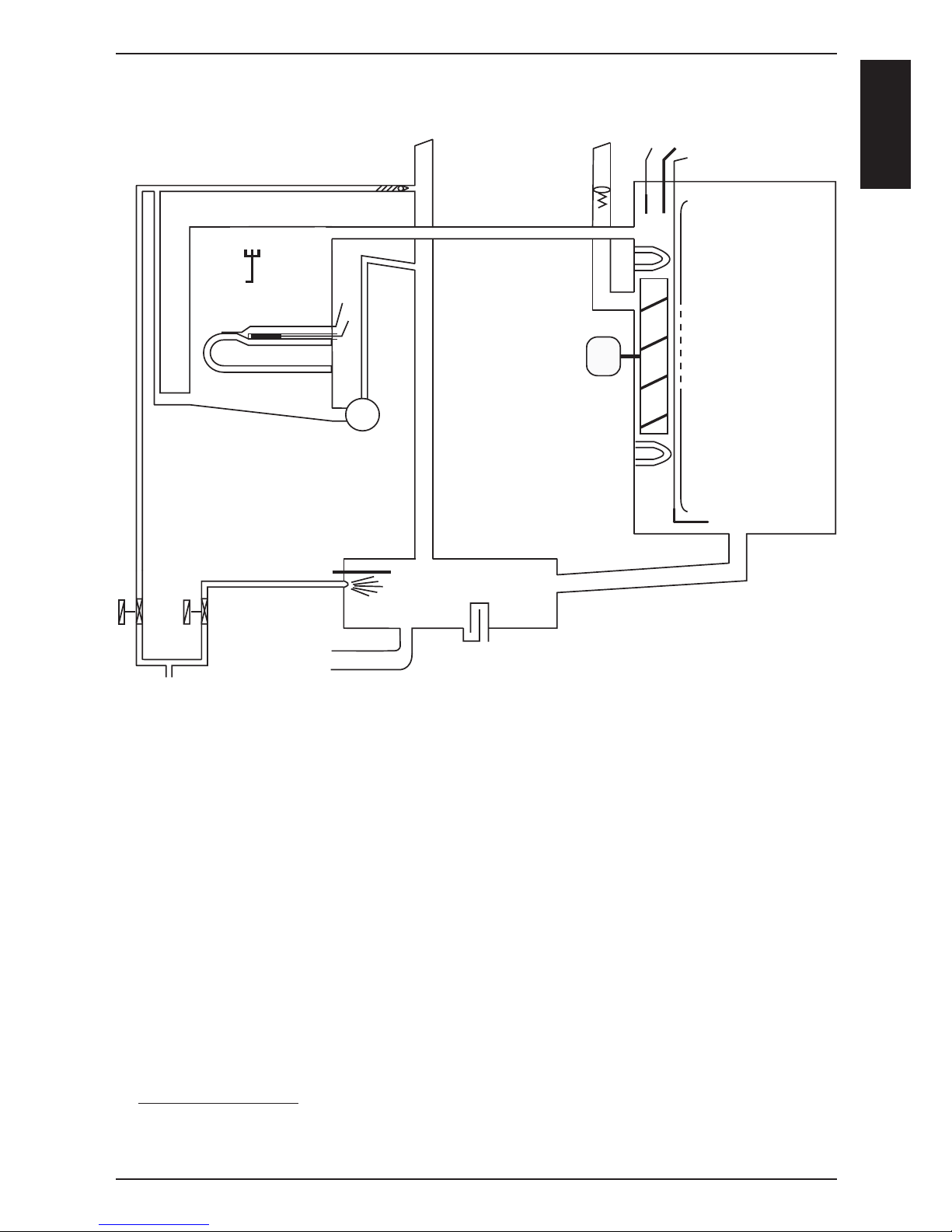
CM Technique from 04 - 2004
B1 Thermocouple cabinet
B2 Thermocouple quenching / Steam control
B3 Thermocouple core temperature
B5 Thermocouple steam generator (preheating, 180°C (356°F) max)
F3 Safety temperature limiter steam generator 160°C
F4 Safety temperature limiter cabinet 360°C
Y1 Solenoid valve fi lling
Y2 Solenoid valve quenching
M1 Fan motor (without jumper)
M4 SC-pump
S2 Level electrode
CM 201/202 only:
M2 Fan motor top (with jumper)
Page 6

-6-
S
C
M
Water level control Steam Generator
V
AC
S2
M4
Y1
Y2
B2
S2
B5
F3
Center S2 ==> Ground: 2 - 6V AC: water level too low
steam heating must switch OFF
solenoid valve fi lling Y1 ON
Center S2 ==> Ground: 0V AC: water level reached
steam heating can switch ON
solenoid valve fi lling Y1 switched OFF
Every 2 minutes steam elements will switch off for water level control
Notes:
X12
Page 7
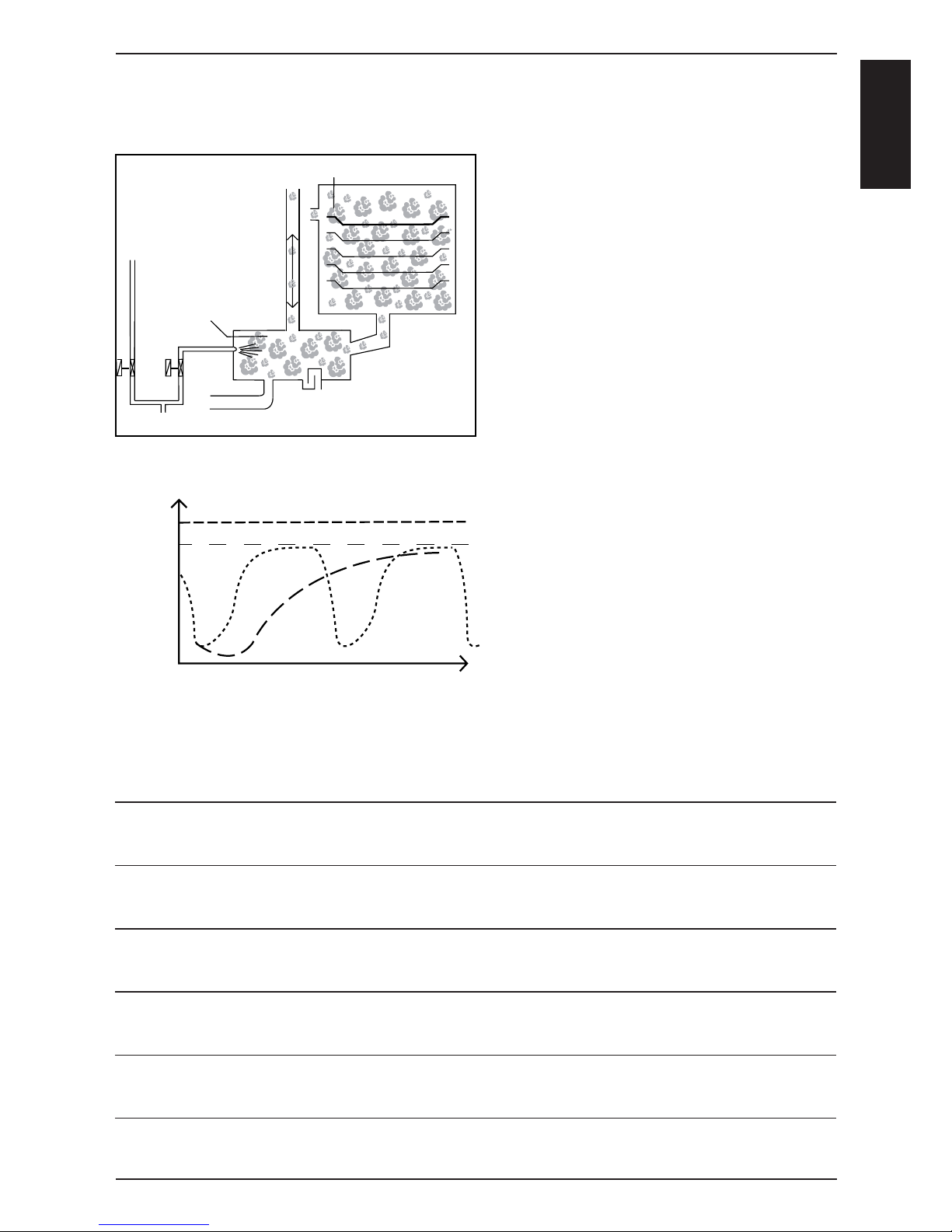
-7-
S
C
M
Y1
Y2
B2
B1
°C / °F
t (sec)
B2 - 2
B2 - 1
B1 - 100°C(212°F)
70°C
(158°F)
1. Filling of interior cabinet based on time
and temperature control of B1 cabinet sensor
2. After steam saturation inside cabinet
steam will also fi ll quenching chamber
3. Depending on the frequency of temperature raise of the quenching sensor B2 the
duration of the next steam supply is
calculated.
B2-1: B2 temperature with partial load
B2-2: B2 temperature with full load
4. The amount of steam inside the cabinet is
directly depending on the temperature
variation of quenching sensor B2.
Steam Control CM from 04 - 2004
Intelligent steam control via quenching sensor
Notes:
Page 8
-8-
S
C
M
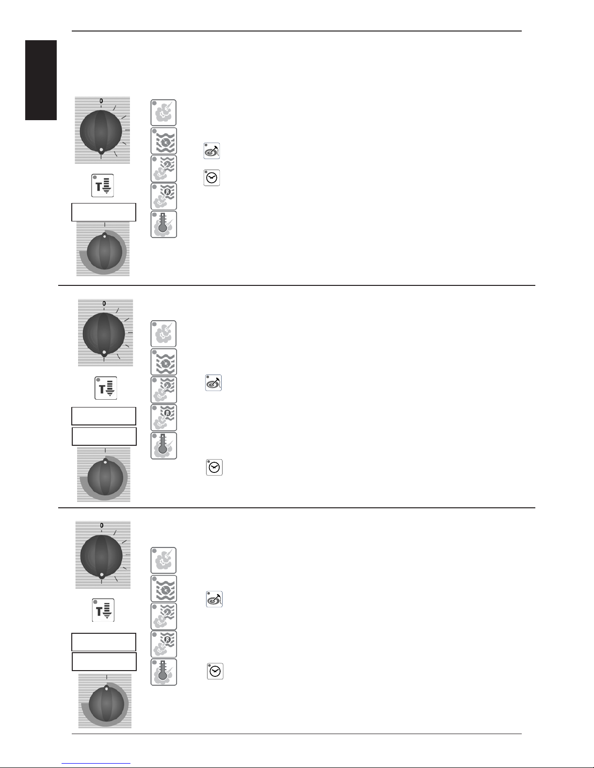
Key code CM from 04 - 2004
CLEn
CLEn
CLEn
SC
CALC
A) Cool down cabinet below 60°C
B) Spray inside cabinet with Rational cleaner
C) Close cabinet door
D) Select „Cool Down
E) Press core temperature key for 10 sec.
F) „CLEn“ will show in cabinet temperature display
G) Press timer key 1x; Cleaning program starts automatically
(open cabinet door and rinse interior cabinet after
40 min.)
Close door again. Since Software version C1-06-05
a 10 min step hot air will follow to dry the interior cabinet.)
H) After end of program, leave cabinet door open over night.
This should be done after each installation to verify free drain connection and before disconnection the unit for storage.
A) Open cabinet door
B) Select „Cool Down“
C) Press core temperature key for 10 sec.
D) „CLEn“ will be shown in cabinet temperature display
E) Select „SC“ with temperature dial
F) Close water tap
G) Press timer key 1x and remain on „Cool Down“ position for
about 45 sec.
A) Open cabinet door
B) Select „Cool Down“
C) Press core temperature key for 10 sec.
D) „CLEn“ will be shown in cabinet temperature display
E) Select „CALC“ with temperature dial
F) Press timer key 1x and follow procedure of the
decalcifi cation instruction. (See user manual CM).
1. Cleaning program
2. Empty steam generator
3. Select descaling program
Page 9

-9-
S
C
M
100°C
212°F
A) Select any mode
C) Press timer and core temperature key
simultaneously for 10 sec. until ==>
D) Display changes from °C to °F or vice versa
E) Release both keys
Key code CM from 04 - 2004
Notes:
4. Changing temperature display from °C to °F
Page 10
-10-
S
C
M
X7
X19
X20
F1 F2
Transformer
0,1 AT
2 AT
1
1
X7
X19
X20
X18
X23
X31
RS 485
X8
X12
X26
X27
X32X24
X30
RS 232
X63
X3X4X6
X2
X50
2 AT
1
2
3
4
on
off
1
1
1
1
1
1
1
F6.1
F6.1
2 AT
2 AT
X16
X16
F6
F6
42.00.004
42.00.047
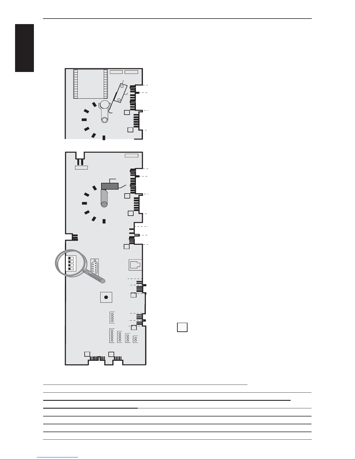
X2 B3 Core temperature
X3 B1 Interior cabinet
X4 B2 Quenching / Steam control
X6 B5 Steam generator
X7 ON - OFF switch
X8 Buzzer
X12 Level electrode
X 16 power supply from transformer (42.00.047)
X18 SC - pump
X19 Solenoid valves
X20 Energy optimising / Sicotronic
X23 Vent hood (signal door open / closed)
X24 SSR
X26 SSR pulsing (USA version only)
X27 Door contact switch
X30 Serial interface (RS232)
X31 BUS interface
X32 Timer / Core Temp. Potentiometer
X50 external EEPROM
X63 Not used
Counting sequence
Notes: Since February 2006 PCB 42.00.004 is replaced by 42.00.047.
(Conversion kit: 87.00.139, pls. see Technical info 04-06)
The transformer on the new PCB 42.00.047 is no more existing and replaced by
external transformer 40.00.227
CM PCB (42.00.004) from 04-2004
1
CM PCB (42.00.047) from 02-2006 (without transformer)
Temperature
potentiometer
Page 11
-11-
S
C
M
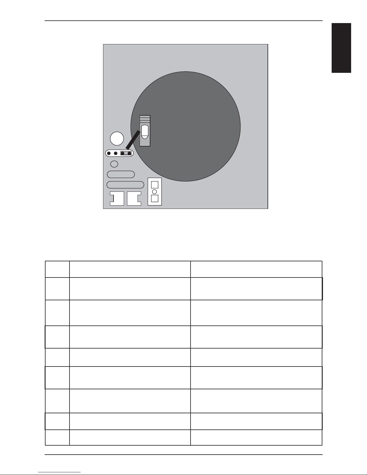
Motor for CM 40.00.274
Jumper 40.01.581 is used on fl oor model 201 and 202 for top position motor only!
Jumper is not used on models 61 - 102 with one motor only! (Service 34 will be shown!)
LED
Jumper
Reason
1x Motor doesn’t start, no changing
signal from hallsensor
2x Voltage too low on motor pcb
3x Voltage too high on motor pcb
4x rpm measurement defective
5x Motor pcb temperature >105°C
6x Supply voltage <80V
7x Motor pcb defective
8x Motor pcb defective
LED code fan motor SCC and CM from 04/2004
Remedy
Check for motor blockage or change motor.
Check supply voltage or
change motor.
Check supply voltage or
change motor.
Change motor.
Check cooling system (cooling fan, air
intake fi lter), otherwise change motor
Check power supply
(F1-F2)
Change motor.
Change motor.
Page 12
-12-
S
C
M
Mode: Steam 100°C (212°F)
Temp. preset, not adjustable
Function Step
Select Steam mode
Select time or core temperature
Close cabinet door
Check water level inside
steam generator
Preheat steam generator,
if B5 is below 85°C (185°F);
Timer starts after successful preheating
Steam supply up to steam saturation
inside cabinet
Hot Air supply (only 50%) when set
temperature (100°C/212°F) can not be
reached in time by Steam alone
Quenching (set to 70°C/158°F)
Responsible sensor
Reed switch S3
Level electrode S2 inside Steam Generator
Thermocouple B5 inside
Steam Generator
Logic on PCB
Quenching sensor B2
(Steam control)
Cabinet sensor B1
Quenching sensor B2
Signal
Door open: 12VDC X27:(1-2)
Door closed: 0VDC X27:(1-2)
X12:(1-4) > 2VAC => no water
X12:(1-4) ~ 0VAC => water
SSR active: 12VDC X24:(1-2)+(5-6)
SSR not act: 0VDC X24:(1-2)+(5-6)
Gas units: Bus signal
SSR active: 12VDC X24:(1-2)+(5-6)
SSR not act.: 0VDC X24:(1-2)+(5-6)
Gas units: Bus signal
SSR active: 12VDC X24:(7-8)
SSR not act.: 0VDC X24:(7-8)
Gas units: Bus signal
B2 above set Temp.: Y2 active
B2 below set Temp.: Y2 not active
Remark
Solenoid Y1 energizes when
no water, 230VAC, X19:(1-3)
Heating off,
if B5 > 180°C (356°F)
Blinking dot in timer
Steam saturation is calculated
by quenching duration and rate
Decision of Hot Air supply by
PCB logic
Y2 active: 230VAC X19:(2-4)
Y2 not act.: 0VAC X19:(2-4)
1
2
3
4
5
6
7
8
9
Page 13
-13-
S
C
M
Mode: Low temperature steam
Temp. range
30-99°C (86-210°F)
Function Step
Select vario steam mode
(Temp. setting 30-99°C (86-210°F))
Select time or core temperature
Close cabinet door
Check water level inside
steam generator
Preheat steam generator,
if B5 is below 85°C (185°F);
Timer starts after successful preheating
Steam supply until set temperature
inside cabinet is reached
Hot Air supply (only 50%) when set
temperature can not be reached
in time by Steam alone
Quenching (set to 70°C/158°F)
Responsible sensor
Reed switch S3
Level electrode S2 inside Steam Generator
Thermocouple B5 inside
Steam Generator
Logic on PCB
Cabinet sensor B1
Cabinet sensor B1
Thermocouple B2
Signal
Door open: 12VDC X27:(1-2)
Door closed: 0VDC X27:(1-2)
X12:(1-4) > 2VAC => no water
X12:(1-4) ~ 0VAC => water
SSR active: 12VDC X24:(1-2)+(5-6)
SSR not act: 0VDC X24:(1-2)+(5-6)
Gas units: Bus signal
SSR active: 12VDC X24:(1-2)+(5-6)
SSR not act.: 0VDC X24:(1-2)+(5-6)
Gas units: Bus signal
SSR active: 12VDC X24:(7-8)
SSR not act.: 0VDC X24:(7-8)
Gas units: Bus signal
B2 above set Temp.: Y2 active
B2 below set Temp.: Y2 not active
Remark
Solenoid Y1 energizes when no
water, 230VAC, X19:(1-3)
Heating off,
if B5 > 180°C (356°F)
Blinking dot in timer
Blinking dot in timer display
Decision of Hot Air supply by
PCB logic
Y2 active: 230VAC X19:(2-4)
Y2 not act.: 0VAC X19:(2-4)
1
2
3
4
5
6
7
8
9
Note:
Below 100°C (212°F) fan at lowest speed when no energy required for longer than 2 minutes.
Page 14
-14-
S
C
M
Mode: Combination
Temp. range
30-300°C (86-572°F)
Function Step
Select Combination mode
(Temp. 30-300°C (86-572°F))
Select time or core temperature
Close cabinet door
Check water level inside
steam generator
Preheat steam generator,
if B5 is below 85°C (185°F);
Timer starts after successful preheating
Hot Air supply until set temperature
inside cabinet.
Hot air has priority
Steam supply up to steam saturation
inside cabinet
Quenching (set to 70°C/158°F)
Responsible sensor
Reed switch S3
Level electrode S2 inside Steam Generator
Thermocouple B5 inside
Steam Generator
Logic on PCB
Cabinet sensor B1
Quenching sensor B2
(Steam control)
Quenching sensor B2
Signal
Door open: 12VDC X27:(1-2)
Door closed: 0VDC X27:(1-2)
X12:(1-4) > 2VAC => no water
X12:(1-4) ~ 0VAC => water
SSR active: 12VDC X24:(1-2)+(5-6)
SSR not act: 0VDC X24:(1-2)+(5-6)
Gas units: Bus signal
SSR active: 12VDC X24:(7-8)
SSR not act.: 0VDC X24:(7-8)
Gas units: Bus signal
SSR active: 12VDC X24:(1-2)+(5-6)
SSR not act.: 0VDC X24:(1-2)+(5-6)
Gas units: Bus signal
B2 above set Temp.: Y2 active
B2 below set Temp.: Y2 not active
Remark
Solenoid Y1 energizes when
no water, 230VAC, X19:(1-3)
Heating off,
if B5 > 180°C (356°F)
Blinking dot in timer
Hot air supply active, until
set temperature is reached
Steam saturation is calculated
by quenching duration and rate
Y2 active: 230VAC X19:(2-4)
Y2 not act.: 0VAC X19:(2-4)
1
2
3
4
5
6
7
8
9
Note:
Below 100°C (212°F) fan at lowest speed when no energy required for longer than 2 minutes.
Page 15
-15-
S
C
M
Mode: Finishing
Temp. range
30-300°C (86-572°F)
Function Step
Select Finishing
(Recom. Temp. 100-140°C (212-284°F))
Select time or core temperature
Close cabinet door
Check water level inside
steam generator
Preheat steam generator,
if B5 is below 85°C (185°F);
Timer starts after successful preheating
Hot Air supply
Electric units: 12 sec on - 6 sec off
Gas units: 30 sec on - 15 sec off
Steam supply
Electric units: 6 sec on - 12 sec off
Gas units: 15 sec on - 30 sec off
Quenching (set to 70°C/158°F)
Responsible sensor
Reed switch S3
Level electrode S2 inside Steam Generator
Thermocouple B5 inside
Steam Generator
Logic on PCB
Cabinet sensor B1
Quenching sensor B2
(Steam Control)
Quenching sensor B2
Signal
Door open: 12VDC X27:(1-2)
Door closed: 0VDC X27:(1-2)
X12:(1-4) > 2VAC => no water
X12:(1-4) ~ 0VAC => water
SSR active: 12VDC X24:(1-2)+(5-6)
SSR not act: 0VDC X24:(1-2)+(5-6)
Gas units: Bus signal
SSR active: 12VDC X24:(7-8)
SSR not act.: 0VDC X24:(7-8)
Gas units: Bus signal
SSR active: 12VDC X24:(1-2)+(5-6)
SSR not act.: 0VDC X24:(1-2)+(5-6)
Gas units: Bus signal
B2 above set Temp.: Y2 active
B2 below set Temp.: Y2 not active
Remark
Solenoid Y1 energizes when no
water, 230VAC, X19:(1-3)
Heating off,
if B5 > 180°C (356°F)
Blinking dot in timer
Hot air supply active, until
set temperature is reached
Steam saturation is calculated
by quenching duration and rate
Y2 active: 230VAC X19:(2-4)
Y2 not act.: 0VAC X19:(2-4)
1
2
3
4
5
6
7
8
9
NOTE: For initial heating of cabinet => alternately energy supply of Hot Air and Steam (Electric 12/6 sec, Gas 30/15 sec)
F
Note:
Below 100°C (212°F) fan at lowest speed when no energy required for longer than 2 minutes.
Page 16
-16-
S
C
M
Mode: Hot Air
Temp. range
30-300°C (86-572°F)
Function Step
Select Hot Air
(Temp. 30-300°C (86-572°F))
Select time or core temperature
Close cabinet door
Timer starts at once
Hot Air supply until set temperature
inside cabinet is reached
Quenching (set to 90°C/194°F)
Responsible sensor
Reed switch S3
Logic on PCB
Cabinet sensor B1
Quenching sensor B2
Signal
Door open: 12VDC X27:(1-2)
Door closed: 0VDC X27:(1-2)
SSR active: 12VDC X24:(7-8)+(3-4)
SSR not act.: 0VDC X24:(7-8)+(3-4)
B2 above set Temp.: Y2 active
B2 below set Temp.: Y2 not active
Remark
Blinking dot in timer display
Y2 active: 230VAC, X19:(2-4)
Y2 not act.: 0VAC, X19:(2-4)
1
2
3
4
5
6
Note:
Below 100°C (212°F) fan at lowest speed when no energy required for longer than 2 minutes.
Page 17
-17-
S
C
M
X7
X19
X20
F1 F2
Transformer
0,1 AT
2 AT
1
1
X7
X19
X20
X18
X23
X31
RS 485
X8
X12
X26
X27
X32X24
X30
RS 232
X63
X3X4X6
X2
X50
2 AT
1
2
3
4
on
off
1
1
1
1
1
1
1
F6.1
F6.1
2 AT
2 AT
X16
X16
F6
F6
42.00.004
42.00.047
1
2
3
4
on
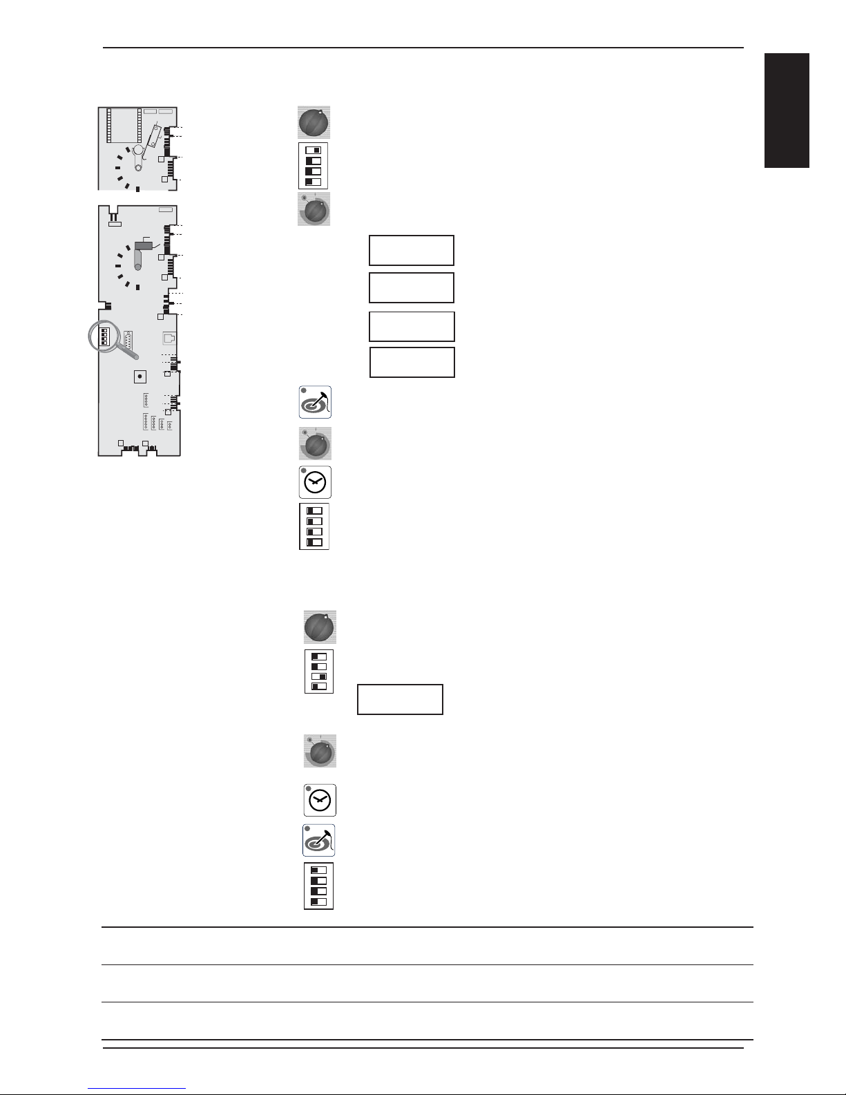
Switch unit ON
On operator PCB set DIP switch 1 to „ON“ position
Select service package with timer dial:
Diagnostic Program
Error code history
Running times
Basic settings
Activate with core temperature key the desired service package
Select with timer dial the desired step
Activate selected step by pressing timer key
To de-activate service package set DIP switch 1 to „OFF“ position
.
Switch unit ON
On operator PCB set DIP switch 3 to „ON“ position
First step of function test is displayed
Select desired step of function test with timer dial
Activate selected step by pressing timer key
Activate selected step with core temperature key
To de-activate function test set DIP switch 3 to „OFF“ position.
A)
B)
C)
D)
E)
F)
G)
A)
B)
C)
D)
E)
F)
G)
dP
SE
rt
1
2
3
4
on
Function Test
Service level CM from 04 - 2004
F1
1
2
3
4
on
1
2
3
4
on
Notes:
Er
Page 18
-18-
S
C
M
Description
Software Version
B1 Cabinet sensor
B2 Quenching sensor
B3 Core sensor
B5 Steam generator sensor
PCB temperature
S3 Door contact
S2 Water level steam
generator
Steam elements
0 - off; 1 - 50%; 2 - 100%
Hot Air elements
0 - off; 1 - 50%; 2 - 100%
Speed fan motor top
Speed fan motor bottom
Energy optimising
(Sicotronic)
SSR pulsing (US version)
Unit size and type
Flame Current Steam
Flame Current Hot Air top
Flame Current Hot Air bottom
dP #
dP 1
dP 2
dP 3
dP 4
dP 5
dP 6
dP 7
dP 8
dP 9
dP 10
dP 11
dP 12
dP 13
dP 14
dP 15
dP 16
dP 17
dP 18
Connector
X 3
X 4
X 2
X 6
X27:(1-2)
X12:(1-4) S2
X19:(1-3) Y1
BUS
BUS
X 20
X 26
Cabinet display
Software
version: C - 1 -
actual value
actual value
actual valuet
actual value
actual value
S3: 1 - 0
Temp. B5
Temp. B1
Set rpm
Set rpm
61 - 202
Timer display
Software
Version:06.05
max value
max value
max value
max value
max value
1 - 0
Y1: 1 - 0
0 - 1 - 2
0 - 1 - 2
actual rpm
actual rpm
1 - 0
1 - 0
ELE - GAS
x.x µA
*
x.x µA*
x.x µA
*
Comment
Reset by pressing
for 5 sec.
Reset by pressing
for 5 sec.
Reset by pressing
for 5 sec.
Reset by pressing
for 5 sec.
Reset by pressing
for 5 sec.
USA version only
since SW Version:
C1-06-05 (fl ame current)
since SW Version:
C1-06-05 (fl ame current)
since SW Version:
C1-06-05 (fl ame current)
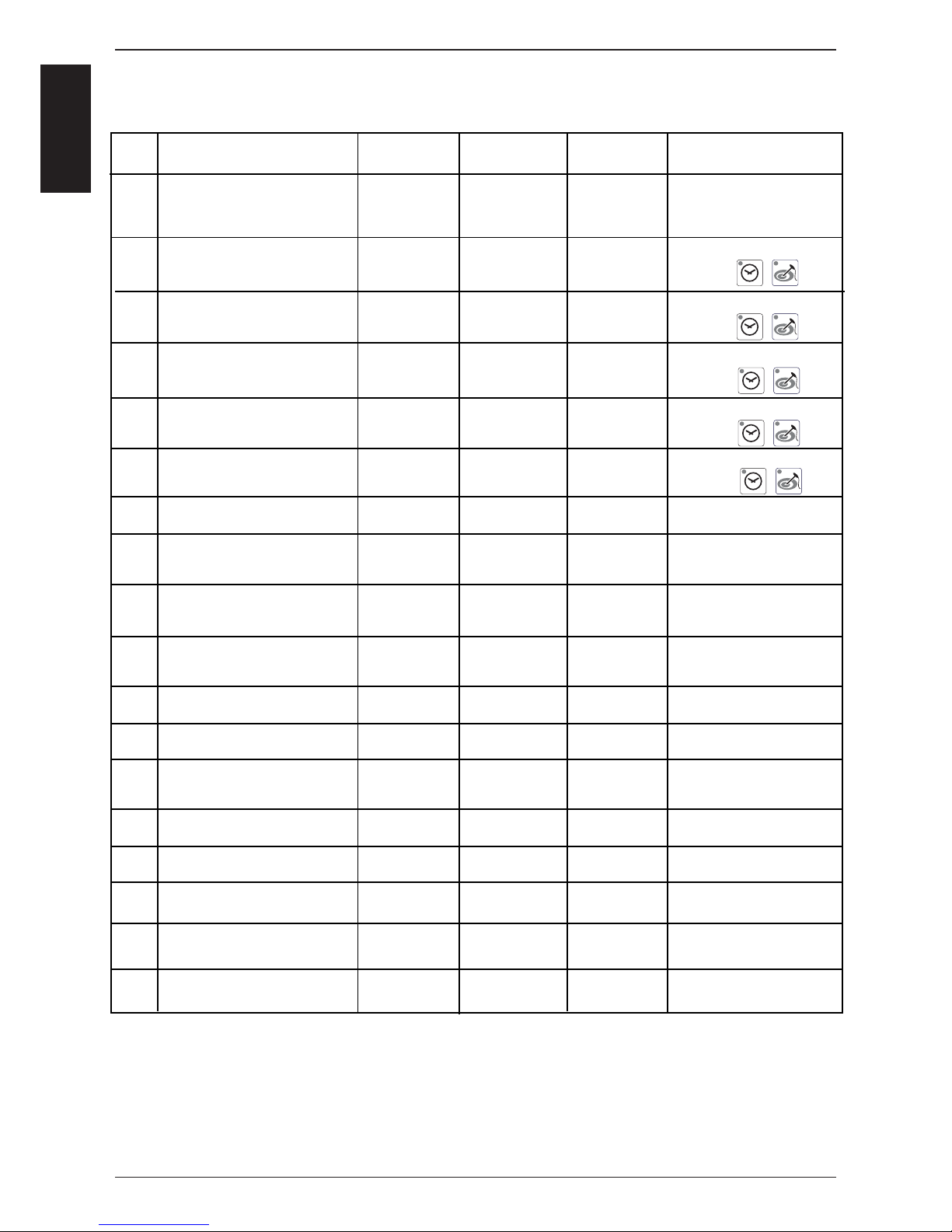
Service level: dP -- Diagnostic Program
+
*
With SW Version C1-06-05 the fl ame current will show as 20-24µA
(This value must be divided by 4 to get the correct fl ame current e. g. 22:4 = 5,5µA.)
Starting with SW version C1-07-01 the actual fl ame current is shown .
+
+
+
+
Page 19
-19-
S
C
M
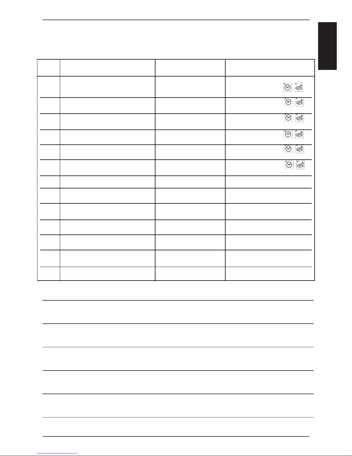
Service Level: rt -- Running Time
rt #
rt 1
rt 2
rt 3
rt 4
rt 5
rt 6
rt 7
rt 8
rt 9
rt 10
rt 11
rt 12
rt 13
Description
Total S3 door openings
Total time Y1 valve fi lling
Total time Y2 valve quenching
Total time M4 SC-pump
Total time steam heating time
Total time hot air heating time
Total time steam mode
Total time hot air mode
Total time combination mode
Total time vario steam mode
Total time fi nishing mode
Total time cleaning program
Total running time unit
Timer display: 1-999
Temp. display: >1000
number
min
min
min
hrs
hrs
hrs
hrs
hrs
hrs
hrs
hrs
hrs
Comment
Reset by pressing
for 5 sec.
Reset by pressing
for 5 sec.
Reset by pressing
for 5 sec.
Reset by pressing
for 5 sec.
Reset by pressing
for 5 sec.
Reset by pressing
for 5 sec.
Can not be reset
Can not be reset
Can not be reset
Can not be reset
Can not be reset
Can not be reset
Can not be reset
+
+
+
+
+
+
Notes:
Page 20
-20-
S
C
M
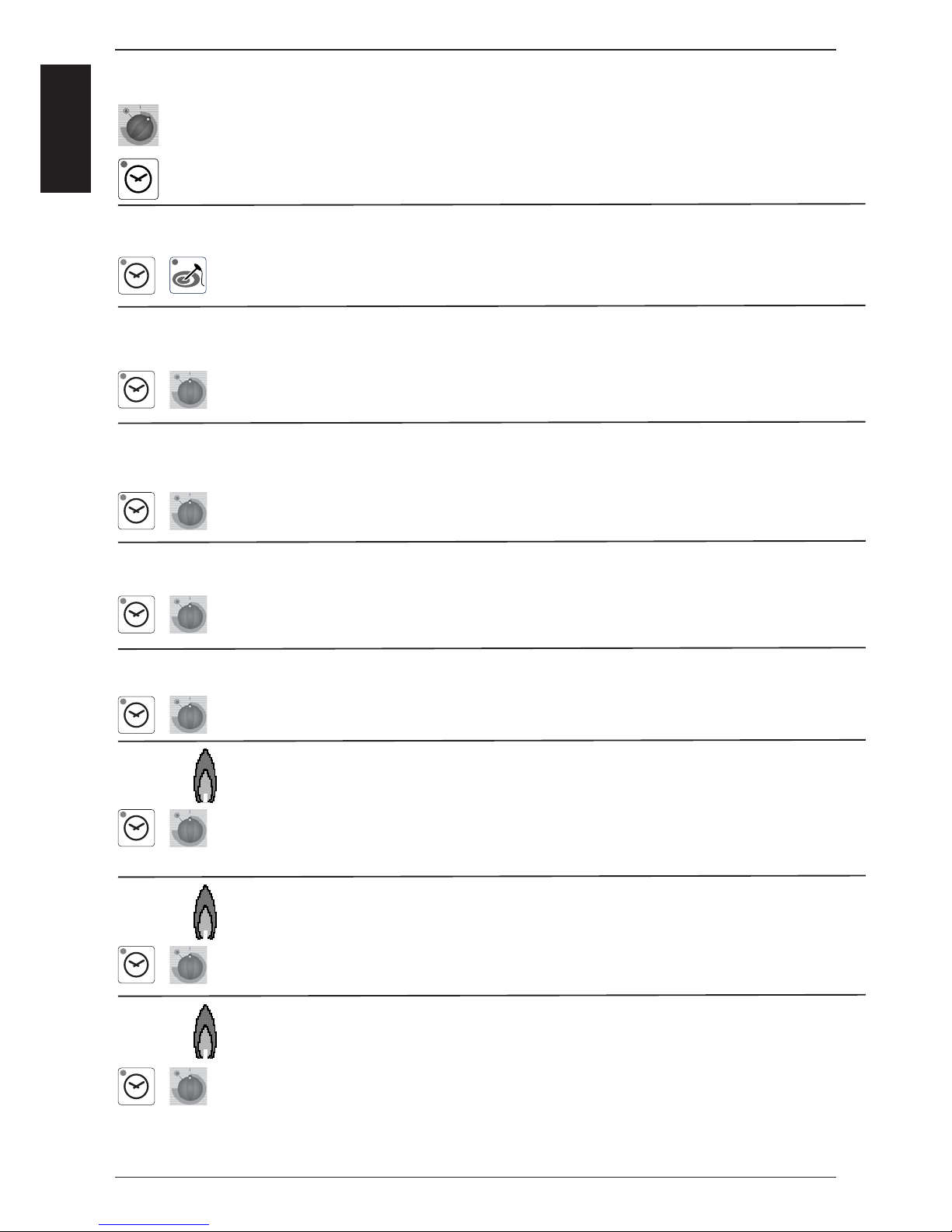
Service level: SE -- Basic settings
Select desired step with timer dial
(fan motor and heating elements are automatically OFF)
Activate selected step with timer key
Steam heating time since last SC-Automatic
Press time and core key simultaneously for 5 seconds to set steam heating time to
preset steam heating time plus 1 minute ==> test function for SC-Automatic
Preset Steam heating time until SC-Automatic
(default 45min)
Press time key and adjust preset steam heating time from 20 - 120 minutes with
timer dial
Flushing time SC-Automatik
(default 45 seconds)
Press time key and adjust fl ushing time of SC-automatik from 30 - 90 seconds with
timer dial
Operation steam generator pump
(oFF - continous or on - pulsing)
Press time key and select „on“ or „oFF“ with timer dial
Show mode (on - oFF) SHO
Press time key and select „on“ or „oFF“ in with timer dial
Setting new gas type (G20, G25, G30, G31, 13A)
Press time key, keep it pressed and select new gas type with timer dial
Confi rm new gas type by pressing core temperature key once
NOTE: After changing gas type a waste gas analysis must be carried out in the function test. Corresponding gas blower speed is automatically adjusted
Presetting of CO2 screw on gas valve after gas type modifi cation / changing gas valve
Press time key, keep it pressed and select with timer dial “ST“ for steam, “HA1“ for
hot air top or “HA2“ for hot air bottom (only 201/202) with timer dial;
Average lenght in mm of CO2 screw on gas valve is shown on timer display
Adjustment of installation altitude above sea level (since SW C1-06-05)
-500- -1m, 0-999m, 1000-1499m, 1500-1999m, 2000-2499m, 2500-2499m, 30003499m, 3500-3499m, 4000-4499m, 4500-4499m
Press time key, keep it pressed and select installaton altitude in 500m steps by timer
dial. Confi rm altitude setting by pressing simultaneously core temperature key once.
SE 1
SE 2
+
SE 3
SE 4
SE 5
SE 6
SE 7
SE 8
+
+
+
+
+
+
Page 21

-21-
S
C
M
Adjusting speed of blower motor steam (+/ -10%)
(After blower speed adjustment the original rpm is shown in the temp. display, the
changed rpm is shown in the time display)
Press time key, keep it pressed and adjust displayed rpm with timer dial
SE9 = MIN rpm; SE10 = Start rpm; SE11 = MAX rpm
Always check CO
2
values of MAX rpm and MIN rpm in function test
Adjusting speed of blower motor hot air top (+/ -10%)
(After blower speed adjustment the original rpm is shown in the temp. display, the
changed rpm is shown in the time display)
Press time key, keep it pressed and adjust displayed rpm with timer dial
SE12 = MIN rpm; SE13 = Start rpm; SE14 = MAX rpm
Always check CO2 values of MAX rpm and MIN rpm in function test
Adjusting speed of blower motor hot air bottom (+/ -10%)
(After blower speed adjustment the original rpm is shown in the temp. display, the
changed rpm is shown in the time display)
Press time key, keep it pressed and adjust displayed rpm with timer dial
SE15 = MIN rpm; SE16 = Start rpm; SE17 = MAX rpm
Always check CO2 values of MAX rpm and MIN rpm in function test
SE 9,10,11
+
SE 12,13,14
+
SE 15,16,17
+
Notes:
Service Level: SE -- Basic settings
Page 22
-22-
S
C
M
Function Connection
I/O PCB
Cabinet
Display
Time
Display
Comment
F1 Steam 50%, Electric unit X24:(1-2) actual temp.
B5 steam generator
1 / 0 Gas:
no function
F2 Steam 100%, Electric unit X24:(1-2)+(5-6) actual temp.
B5 steam generator
1 / 0 Gas:
no function
F3 Hot Air 50%, Electric unit X24:(7-8) actual temp.
B1 cabinet
1 / 0 Gas:
no function
F4 Hot Air 100%, Electric unit X24:(7-8)+(3-4) actual temp.
B1 cabinet
1 / 0 Gas:
no function
F5 Steam, Gas unit BUS actual temp.
B5 steam
generator
1 / 0 Electric:
no function
F6 Hot Air Top, Gas unit BUS actual temp.
B1 cabinet
1 / 0 Electric:
no function
F7 Hot Air Bottom, Gas unit BUS actual temp.
B1 cabinet
1 / 0 Electric:
no function
F8 Bottom Motor MAX speed BUS Set rpm Act. rpm
F9 Bottom Motor MIN speed BUS Set rpm Act. rpm
F10 Top Motor MAX speed BUS Set rpm Act. rpm
F11 Top Motor MIN speed BUS Set rpm Act. rpm
F12 Solenoid valve quenching X19:(2-4) actual temp.
B2 quenchingY21 / 0
F13 Solenoid valve fi lling X19:(1-3) Level electrode
S2, 1 / 0
Y1
1 / 0
F14 Steam generator pump X18:(1-2) M4
X12:(1-4) S2
Level electrode
S2, 1 / 0
M4
1 / 0
F15 Buzzer 1 / 0
F16 All Displays / LED
F17 Relais Vent hood
UltraVent
(door open/close)
X 23: (1-2-3) 1 / 0
F18 no function
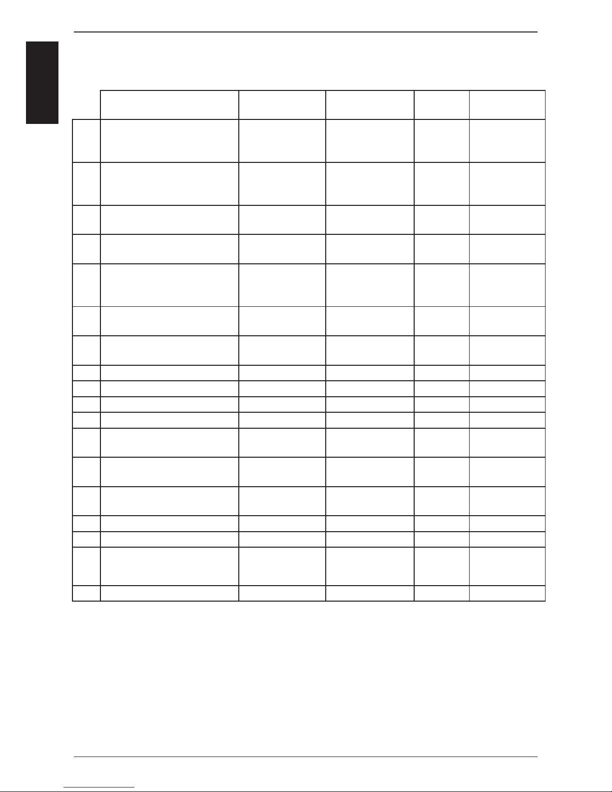
Service level: F -- Function test
NOTE: In Function test components are NOT protected against overload!
Page 23

-23-
S
C
M
Service level: F -- Function test
NOTE: In Function test components are NOT protected against overload!
Connection
I/O PCB
BUS
BUS
BUS
BUS
BUS
BUS
BUS
BUS
BUS
Cabinet
Dispaly
Actual blower
rpm
Actual blower
rpm
Actual blower
rpm
Actual blower
rpm
Actual blower
rpm
Actual blower
rpm
Actual blower
rpm
Actual blower
rpm
Actual blower
rpm
Time
Display
Set CO
2
value
Set CO2
value
Set CO2
value
Set CO2
value
Set CO2
value
Set CO2
value
Comment
Check CO
2
value only
Adjust CO2 value
with CO2 screw
on gas valve
Check CO2
value only
Adjust CO2 value
with CO2 screw
on gas valve
Check CO2
value only
Adjust CO2 value
with CO2 screw
on gas valve
F #
F19
F20
F21
F22
F23
F24
F25
F26
F27
Function
Steam blower motor
MIN rpm
Steam blower motor
Start rpm
Steam blower motor
MAX rpm
Hot air blower motor, top
MIN rpm
Hot air blower motor, top
Start rpm
Hot air blower motor, top
MAX rpm
Hot air blower motor,
bottom, MIN rpm
Hot air blower motor,
bottom, Start rpm
Hot air blower motor,
bottom, MAX rpm
Notes:
Page 24
-24-
S
C
M
Since software version C1-07-01 the last 10 error messages are shown.
Er When Timer key is pressed the error code will be displayed, i.e.
Er1 3 B1 Cabinet sensor defective
Er2 14 Y1 Filling solenoid defective
Er3
--
--
Er10
Since software version C1-07-01 the last 16 gas error messages are shown
in addition to the general error messages (gas units only!)
GE11 20 No rpm signal
GE12 32 No fl ame after 5 ignition sequences
GE13
--
-GE25
GE26
Indication of ignition box error messages (1-32 is shown to the operator as „rES“):
1 Hot air or Steam no gas, gas valve or electrode defective
14 Hot air gas valve controll, change ignition box
19 Hot air no fl ame because fl ame current is too low
check burner setting, fl ame current, ignition cable and plug
20 Hot air wrong or no rpm signal from gas blower
check gas blower, power supply gas blower and control harness of gas blower
22 Hot air no fl ame after 5 ignition sequences
no gas, gas valve or electrode defective
24 Steam gas valve controll, change ignition box
29 Steam no fl ame because fl ame current is too low
check burner setting, fl ame current, ignition cable and plug
30 Steam wrong or no rpm signal from gas blower
check gas blower, power supply gas blower and control harness of gas blower
32 Steam no fl ame after 5 ignition sequences
no gas, gas valve or electrode defective
Possible failure in case of „E21“
33, 36 Change ignition box
35 Check frequency of main
39 Hot air Check burner setting, ignition electrode and distance,and fl ame current
40 Hot air Check ignition cable
42 Steam Check burner setting, ignition electrode and distance,and fl ame current
43 Steam Check ignition cable
Is shown on display „CHnG PoL“
34 Change polarity of mains
All other numbers (2-13, 15-18, 21, 23, 25-28, 31): change ignition box
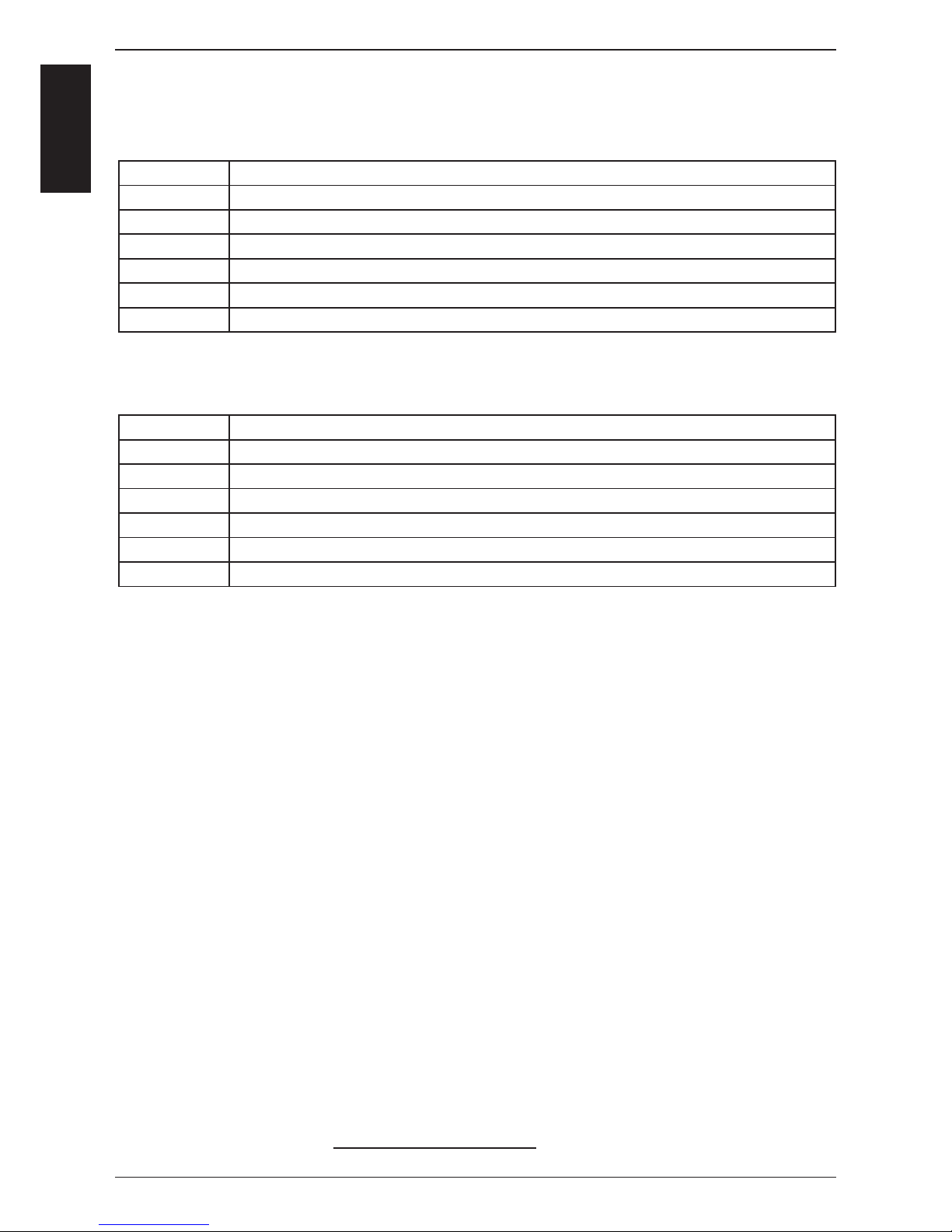
Service Level: ER -- Error code history
Page 25
-25-
S
C
M
Int. cab.
display
H2o
CHnG
Timer
display
E1
E2
E3
E4
E5
E6
E7
E8
E9
E10
E11
E12
E 12
E13
E14
E15
E16
E17
E18
E19
E20
E21
E22
E23
E24
Timer
display
OPEn
PoL
Int. cab.
display
(E -press
core temp.
key)
1 St
1 Co
2 St
2 Co
1_
2_
1xx
2xx
3xx
1xx
2xx
3xx
Failure explanation
H2O open
Change Polarity
Part concerned
external EEPROM
Timeout of external
power optimising system
(Sicotronic)
B1 Interior cabinet sensor
B2 Quenching sensor
B3 Core sensor
B5 Sensor steam generator
Thermocouple on PCB
Poti interior cabinet
Poti timer/core temperature
External EEPROM
Mode switch
Fan motor 1 (bottom)
Fan motor 1 (bottom)
Fan motor 2 (top)
Fan motor 2 (top)
M4 SC-pump
Solenoid valve fi lling Y1
PCB temperature
Steam generator
Steam generator
Interior cabinet temp.
free
Ignition box 1
Ignition box 2
Ignition box 1 Steam
Ignition box 1 Hot air
Ignition box 2 Hot air
Ignition box 1 Steam
Ignition box 1 Hot air
Ignition box 2 Hot air
free
EEPROM
Description
Lack of water / open water tap
Phase / Neutral (only gas units)
Description
Not initialised
Heating blocked by the extern. energyoptimising system for longer 2 min.
Sensor broken
Sensor broken
Sensor broken
Sensor broken
Sensor broken
Defective
Defective
Defective
After 5 sec switching on the unit, a
cooking mode couldn‘t be identifi ed
St = Status (probably Motor defect)
Co = Communication,(Bus failure)
St = Status (probably Motor defect)
Co = Communication,(Bus failure)
Mal function
Mal function
above 85°C (185°F)
Temperature B5 above
180°C (356°F)
Temperature B5 below -5°C (23°F)
Temperature B1 above 340°C (644°F)
Ignition box does not reply, Bus failure
Ignition box does not reply, Bus failure
Ignition box defective (change box)
Ignition box defective (change box)
Ignition box defective (change box)
Testing of ignition and monitoring
necessary
Testing of ignition and monitoring
necessary
Testing of ignition and monitoring
necessary
Actual data structure of the EEPROM
does not match with the software; flash
pcb first
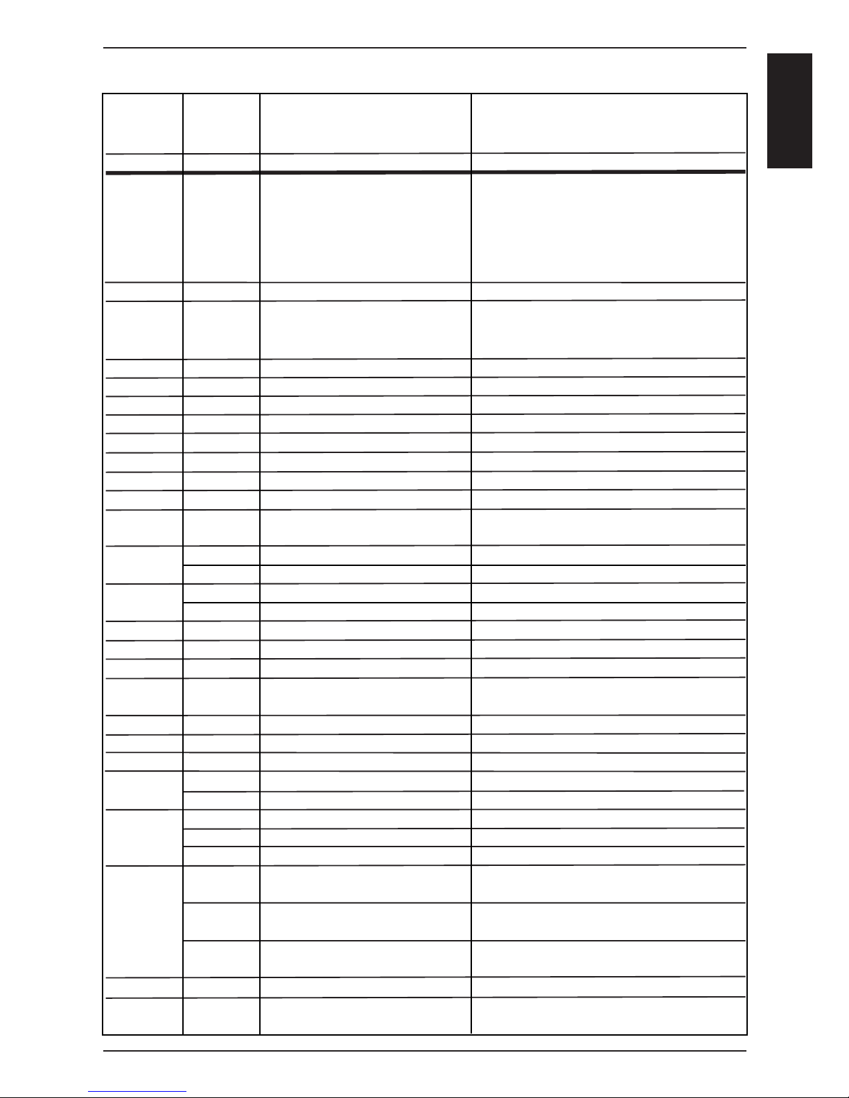
Failure Codes CM from 04-2004
Page 26
-26-
S
C
M
S2
B1
B3
F4
M4
Y1
Y2
B2
M1
B5
F3
M8
M9
Y11
Y12
A5
B11
B12
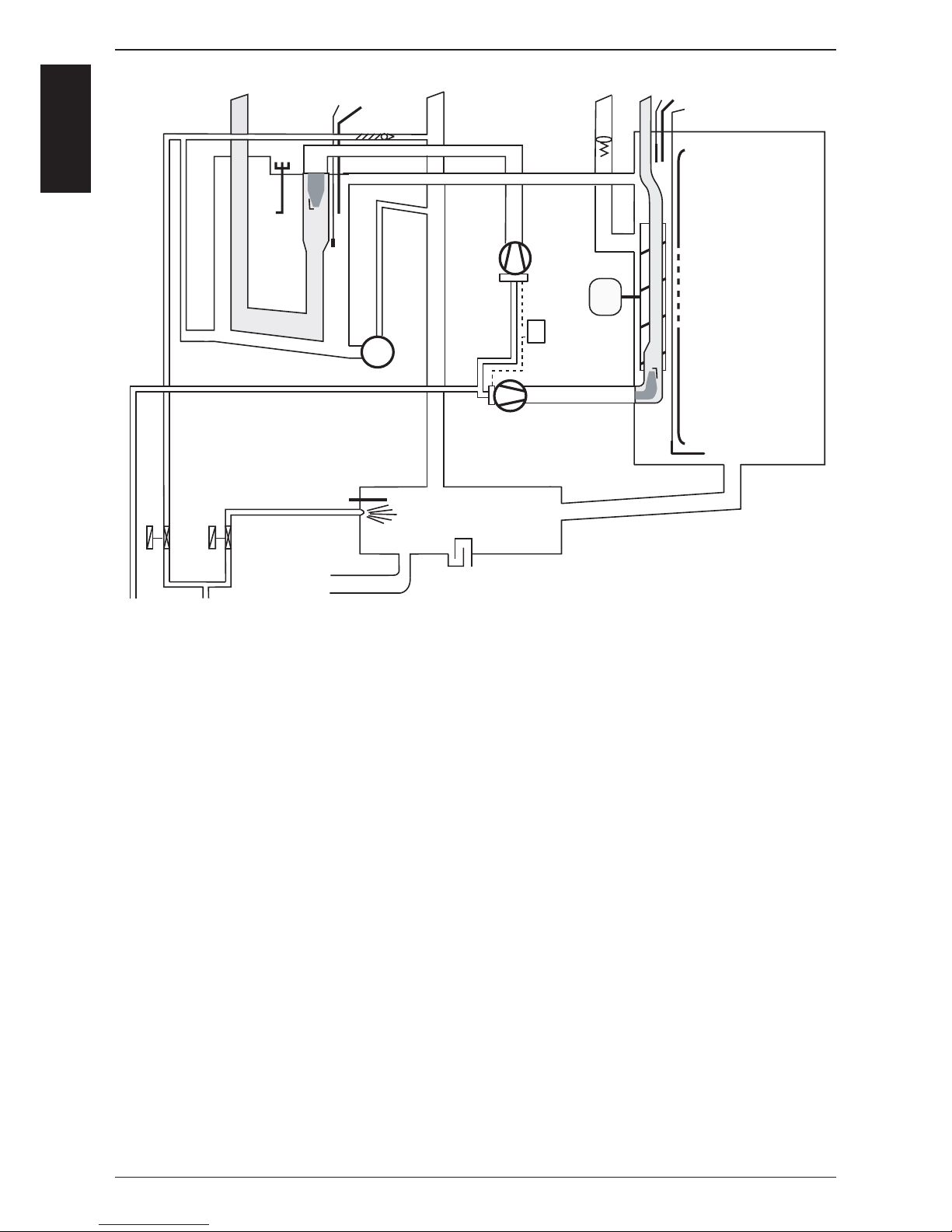
CM Gas from 04 - 2004
A5 Ignition module (Steam and Hot Air) (without jumper)
B1 Thermocouple interior cabinet
B2 Thermocouple quenching / Steam control
B3 Thermocouple core temperature
B5 Thermocouple steam generator
B11 Ignition/monitoring electrode steam
B12 Ignition/monitoring electrode hot air
F3 Safety thermostat steam generator 135°C
F4 Safety thermostat interior cabinet 360°C
M1 Fan motor
M4 SC-pump
M8 Gas blower motor hot air
M9 Gas blower motor steam
Y1 Solenoid valve fi lling
Y2 Solenoid valve quenching
Y11 Gas valve steam
Y12 Gas valve hot air
S2 Level electrode
Only fl oor units 201 - 202
A6 Ignition module hot air bottom (with jumper)
M2 Fan motor top (with jumper)
M10 Gas blower motor hot air bottom
Y13 Gas valve hot air bottom
B13 Ignition/monitoring electrode hot air bottom
Page 27

-27-
S
C
M
Identifi cation of the different gas burners / Gas blowers:
CM 201 - 202
CM 61 - 62 - 101 - 102
Steam Blower
(ignition box fi tted)
Hot Air blower top
(ignition box not fi tted)
Hot Air blower bottom
(ignition box fi tted)
Ignition box of Hot Air Blower, Bottom (201-202):
Jumper must ONLY be set
on Ignition Box for
Hot Air Blower Bottom
(201 - 202)
Gas valve components
Measuring test point for
gas fl ow pressure
Gas supply
Compensation hose
CO
2
Srew
Basic info about CM Gas from 04-2004
Ignition box
Page 28
-28-
S
C
M
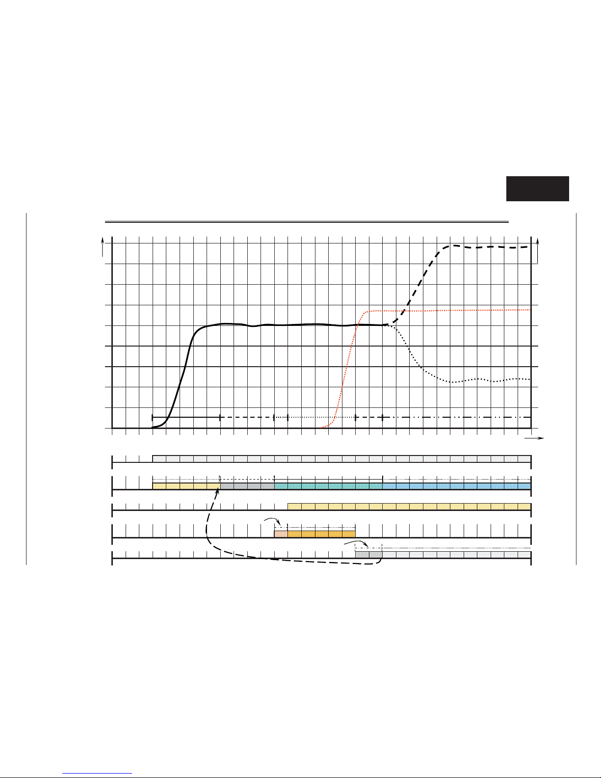
Sequence of events of Steam / Hot Air Burner (SCC as well as CM)
If no flame detected => new ignition sequence. After 5th ignition without success => RESET
16 2419 2017 1810 11 14 15
Speed of burner blower motor in U/min
21 22 23 26 27678901 45
8
4
3
2
1
2512 13
F l a m e c u r r e n t in µA
Time 2 3
7
6
5
Flame monitoring
Energise Solenoids: Black coils ca 205V DC / orange coils ca 108V DC
Ignition box gets heat demand over the BUS cable
Ignition, ca 20KV
Burner blower motor
Gas valve
Heat demand
Start - pre purge
about. 4-5 sec
Pre purge, 4 sec
RPM monitored
Blower runs with Start RPM
RPM monitoring by ignition box
Blower runs with Max or Min RPM
RPM monitoring by ignition box
Flame monitoring within. 2 sec
C
continuous flame control
Start RPM
Max RPM
Min RPM
sec
RPM
Igniti
on,5 secPre ignition, 1sec
Start up Pre purge
Pre ignition
Ignition Burner running
Flame
control
µA
Flame current
Page 29
-29-
S
C
M
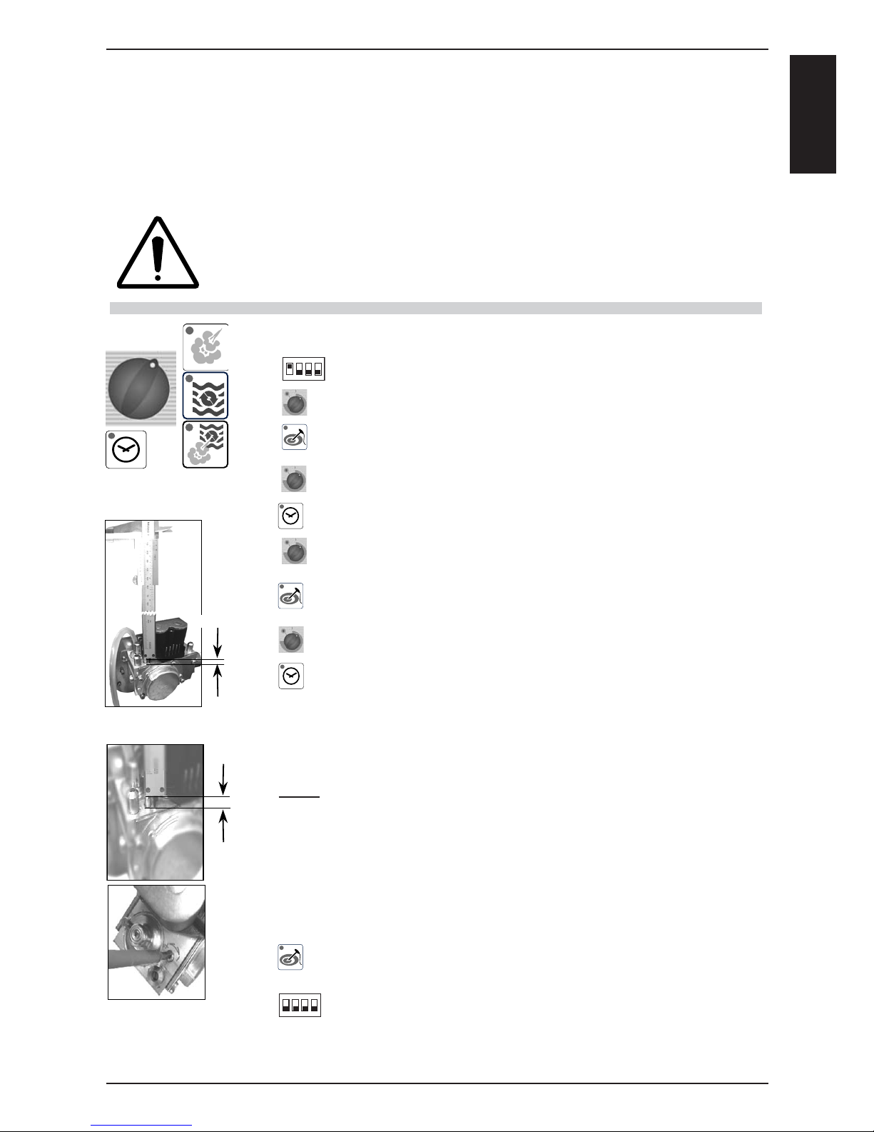
Check Gas Type / Gas Conversion: CM Gas from 04-2004
Select any mode and cooking time
Open control panel
Set DIP switch 1 on PCB to „ON“ position
With timer dial select: „SE“ = Settings:
Activate „Settings“ by pressing core temperature key;
display changes to „SE1“
With timer dial select: SE6
Activate position SE6 with timer key (keep key pressed)
Select new gas type with timer dial:
G20=Nat Gas H, G25=Nat Gas L, G30=3BP, G31=3P, 13A=Nat. Gas Japan
Confi rm new gas type with core temperature key
(now timer key can be released)
With timer dial select: SE7
Activate position SE7 with timer key (keep key pressed)
Keeping the timer key pressed the average length of the CO
2
screw is indicated.
„St“ Steam, „HA1“ Hot air top, HA2“ Hot air bottom
Select the corresponding value with the timer dial (keep timer key pressed).
Note: Setting this screw to the given length shall ONLY bring the unit into wor-
king condition with the newly supplied gas.
This does NOT replace fl ue gas analysis or make the fl ue gas analysis obsolete!
Set the CO2 screw according the values of timer display or according
the table “Values for burner adjustments“ (! ! ! Set all CO2 screws ! ! !)
If the mm setting of CO2 screw is too high, turn CO2 screw fi rst 2 turns clockwise
and then to the requested length (Screw adjustment tolerance)
De-activate selected package “SE“ by pressing core temperature key
To exit service program set DIP switch 1 to „OFF“ position
Check / Set Installation Altitude in Basic settings
Perform fl ue gas analysis in function test at F21, F24, F27
as well as the check of CO2 values at F19, F22, F25
A)
B)
C)
D)
E)
F)
G)
H)
I)
J)
K)
L)
M)
N)
O)
P)
1
234
on
1
234
on
x,x mm
x,x mm
Whenever working on any gas component like:
Gas valve, gas blower and / or changing connected type of gas, a detailed fl ue gas analysis
MUST be done using adequate CO and CO2 measuring equipment!
This shall ONLY be done by trained technicians!
Always check appliance for possible gas leakages!
Danger:
Changing the gas type of your SelfCooking Center or Combi Master
shall only be done if you have a fl ue gas analyser at hand.
Changing the gas setting only by adjusting the CO2 screw
will result in an unsafe fl ue gas condition,
is dangerous to life and will damage the equipment.
Page 30

-30-
S
C
M
Changing installation altitude: CM gas from 04-2004
SE
A)
B)
C)
D)
E)
F)
G)
H)
I)
J)
K)
L)
M)
N)
6250
Select any mode and cooking time
Open control panel
Set DIP switch 1 on PCB to „ON“ position
With timer dial select: „SE“ = Settings.
Activate „Settings“ by pressing core temperature key; display
changes to „SE1“.
With timer dial select: SE8
Activate position SE8 with timer key and keep it pressed.
While pressing timer key corresponding installation altitude above
sea level can be selected with the timer dial.
Possible altitude selection:
-500 - -1m
0 - 499m
500 - 999m
1000 - 1499m
1500 - 1999m
2000 - 2499m
2500 - 2999m
3000 - 3499m
3500 - 3999m
4000 - 4499m
4500 - 4999m
Confi rm new altitude setting with core temperature key
(Keep timer key pressed)
Release timer and core temperature key
De-activate selected package by pressing core temperature key;
To exit service program set DIP switch 1 to „OFF“ position
To store the new altitude setting the unit must be switched
OFF and ON again.
Perform fl ue gas analysis in function test at F21, F24, F27
as well as the check of CO2 values at F19, F22, F25
1
234
on
1
234
on
Note: The altitude settings of 0-499 and 500-999m are identical.
Therefore resetting of installation altitude needs to be done only when installing
above 1000m (3280ft) or below sea level (i.e. Red Sea)
Page 31
-31-
S
C
M
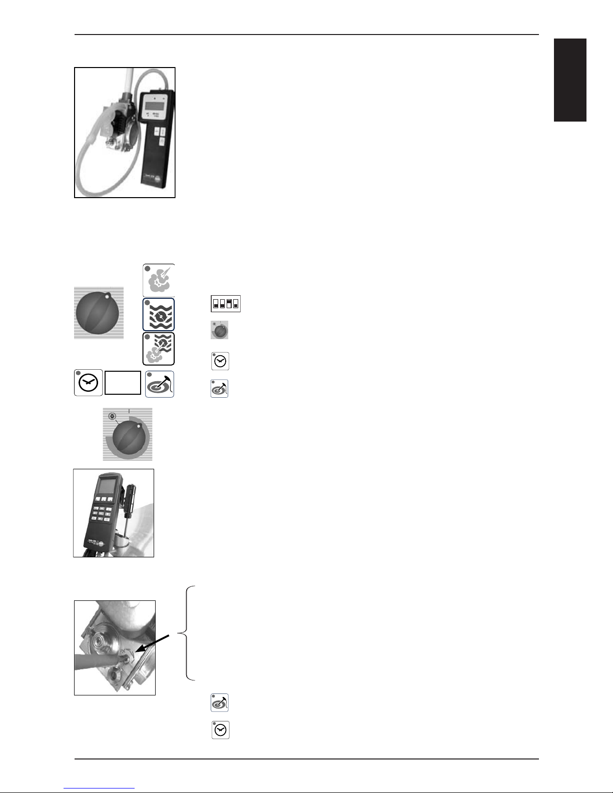
Flue gas analysis: CM gas from 04-2004
Before you carry out a fl ue gas analysis
check input gas fl ow pressure when burner is running
• Switch on unit. Select any mode and cooking time.
Wait till burner works
• Check input gas fl ow pressure
• See correct values of input fl ow pressure on serial plate
• If necessary adjust gas input pressure
F1
A)
B)
C)
D)
E)
F)
G)
H)
I)
J)
K)
Select any mode and cooking time
Open control panel
Set DIP switch 3 on PCB to „ON“ position
„F1“ is shown on timer display. With timer dial select position F21
Enter position F21 „Steam MAX“ with timer key
Activate position F21 with core temperature key;
NOTE: In this position core temp. key is used as a switch and will
automatically deactivate after 4 minutes.
Gas blower rpm is shown in cabinet temp. display.
Specifi c CO2 value is shown on timer display, i.e. 9,5
Place fl ue gas testing nozzle in correct fl ue outlet
Adjust CO2 to given value by turning CO2 screw on gas valve.
You also can fi nd that value on table “Values for burner adjustments“
• If CO2 value is too low => turn CO2 screw
anti clockwise (+ direction),
• If CO2 value is too high => turn CO2 screw fi rst 2 turns clockwise
(- direction), and than slowly anti clockwise (+ direction) till you get the
indicated CO2 value. (Screw adjustment tolerance).
• CO value must be below 300ppm
Press core temperature key. Burner will stop.
Leave position F21 „Steam MAX“ with timer key
Flue gas analysis (F21, F24 und F27) at MAX rpm Checking CO2 (F19, F22 and F25) at MIN rpm
NOTE: Components are NOT protected against overload during function test!
1
234
on
Page 32
-32-
S
C
M
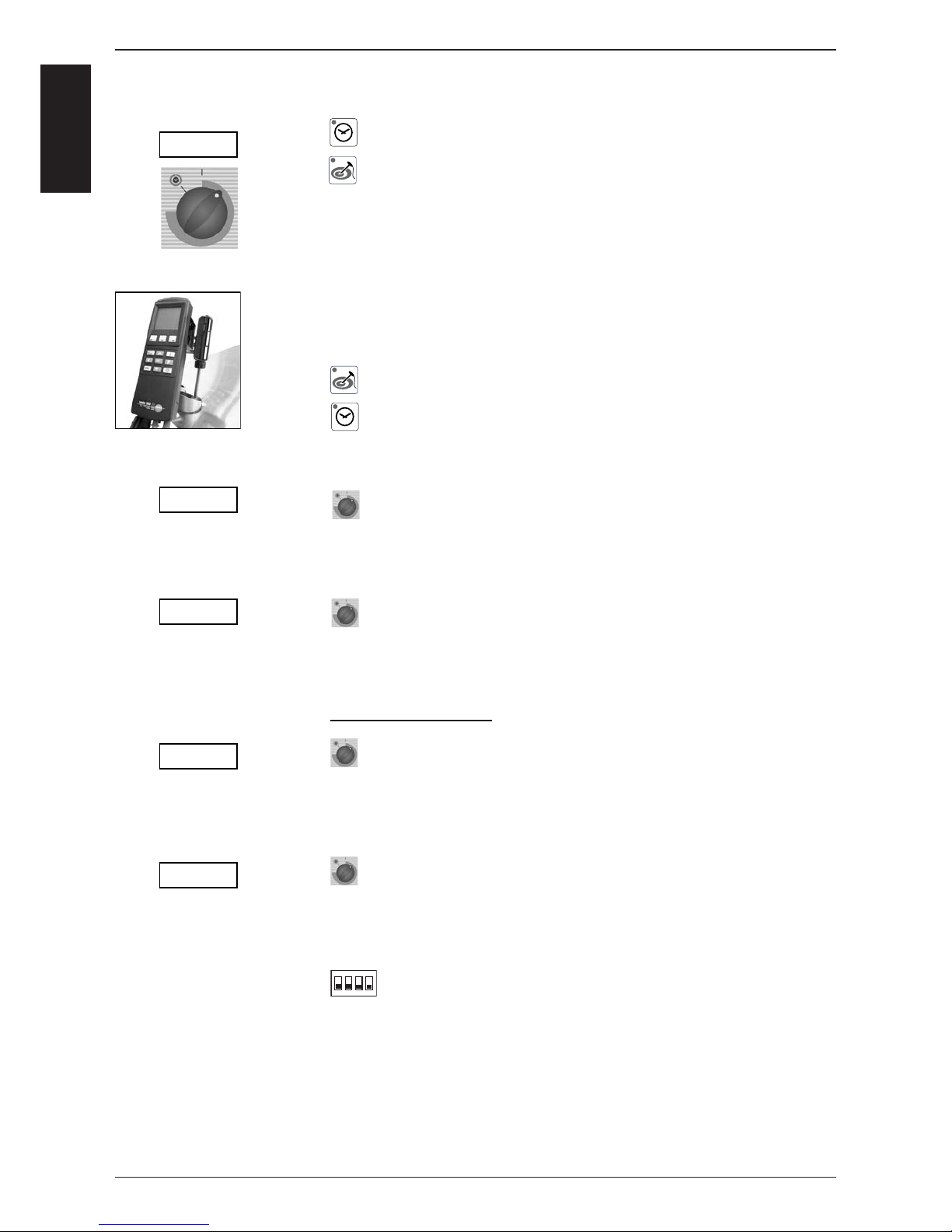
Select position F19 with timer dial and enter „Steam MIN“ with
timer key.
Activate position F19 with core temperature key;
NOTE: in this position core temp. key is used as a switch and will automatically deactivate after 4 minutes.“
Carry out a CO
2
measurement to cross-check CO2 value only.
CO2 value must be equivalent to the values mentioned in table
“Values for burner adjustments“
If CO2 value is out of allowed tolerance
=> Change gas valve
Press core temperature key. Burner will stop.
Leave position F19 „Steam MIN“ with timer key
Select position F24 „Hot air top, MAX“ with timer dial
and repeat steps E - K.
NOTE: Adjust CO2 to given value by turning CO2 screw on gas valve at position F24 „Hot air top, MAX“ only!
Select position F22 „Hot air top, MIN“ with timer dial
and repeat steps L - P
NOTE: Cross-check CO2 value only. If CO2 value is out of allowed tolerance
=> Change gas valve
CM201 and CM202 only:
Select position F27 „Hot air bottom, MAX“ with timer dial
and repeat steps E - K.
NOTE: Adjust CO2 to given value by turning CO2 screw on gas valve at position F27 „Hot air top, MAX“ only!
Select position F25 „Hot Air bottom, MIN“ with timer dial
and repeat steps L - P.
NOTE: Cross-check CO2 value only. If CO2 value is out of allowed tolerance
=> Change gas valve
To exit service program set DIP switch 3 to „OFF“ position
Flue gas analysis: CM gas from 04-2004
1
234
on
L)
M)
N)
O)
P)
Q)
R)
S)
T)
U)
F 19
F 24
F 22
F 27
F 25
Page 33
-33-
S
C
M
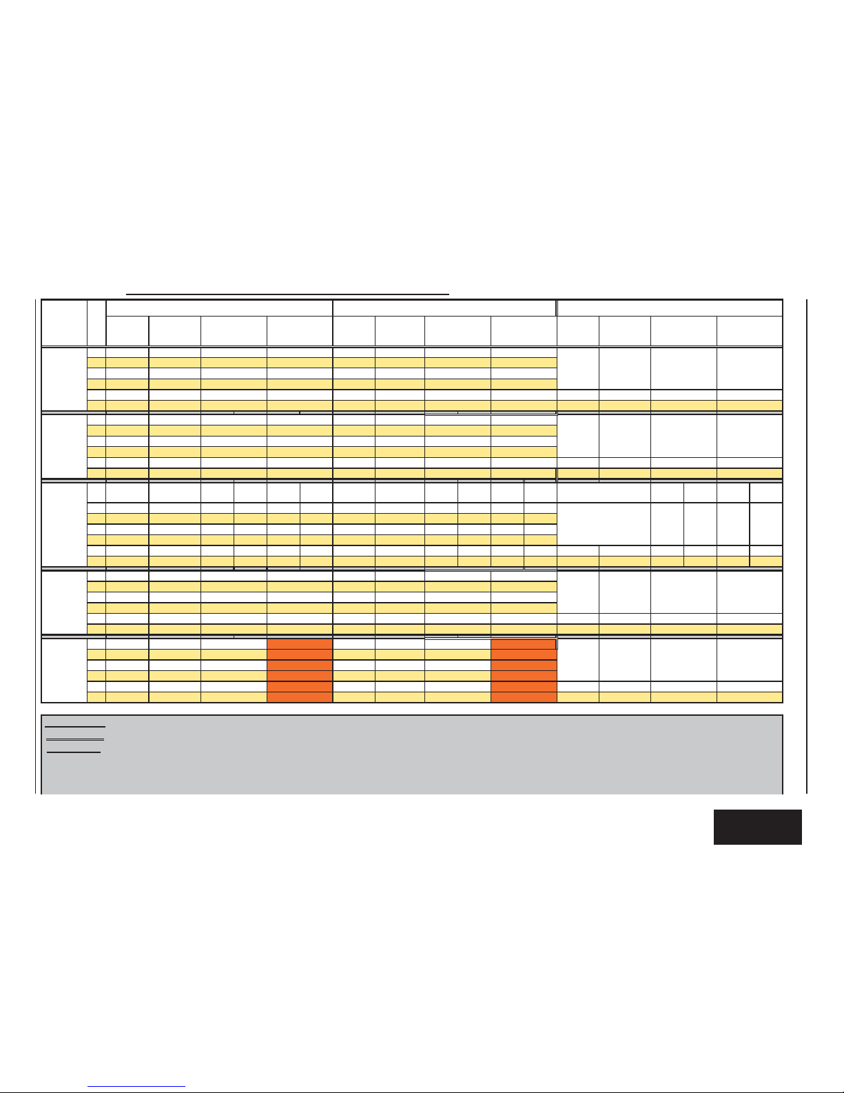
Input gas flow
pressure
Adjustment of
CO
2
- Screw
Input gas flow
pressure
Adjustment of
CO
2
- Screw
Input gas flow
pressure
Adjustment of
CO
2
- Screw
61
18 - 25 mbar
3,9 mm
18 - 25 mbar
3,8 mm
62
18 - 25 mbar 3,4 mm 18 - 25 mbar 3,5 mm
101
18 - 25 mbar 3,3 mm 18 - 25 mbar 3,3 mm
102
18 - 25 mbar 4,1 mm 18 - 25 mbar 3,5 mm
201
18 - 25 mbar 4,1 mm 18 - 25 mbar 3,4 mm 18 - 25 mbar 3,4 mm
202
18 - 25 mbar 4,1 mm 18 - 25 mbar 3,3 mm 18 - 25 mbar 3,3 mm
61
18 - 25 mbar
4,8 mm
18 - 25 mbar
6,0 mm
62
18 - 25 mbar 4,6 mm 18 - 25 mbar 4,7 mm
101
18 - 25 mbar 4,0 mm 18 - 25 mbar 4,3 mm
102
18 - 25 mbar 7,0 mm 18 - 25 mbar 4,5 mm
201
18 - 25 mbar 6,5 mm 18 - 25 mbar 4,2 mm 18 - 25 mbar 4,4 mm
202
18 - 25 mbar 6,5 mm 18 - 25 mbar 4,4 mm 18 - 25 mbar 4,5 mm
3B/P
100%
Butane
3B/P
100%
Butane
3B/P
100%
Butane
3B/P
100%
Butane
3B/P
100%
Butane
3B/P
100%
Butane
61
30 - 57 mbar
2,6 mm
10,4% 11,6% 9.3% 10,6% 30 - 57 mbar
2,5 mm
10,4% 11,6% 9,4% 10,4%
62
30 - 57 mbar 2,4
mm 10,4% 11,6% 8.5% 9,2% 30 - 57 mbar 2,4 mm 10,4% 11,6% 8,1% 9,6%
101
30 - 57 mbar 2,5 mm 10,4% 11,6% 8.4% 9,2% 30 - 57 mbar 2,3 mm 10,4% 11,6% 8,2% 9,6%
102
30 - 57 mbar 2,5 mm 10,4% 11,6% 8.9% 10,1% 30 - 57 mbar 2,4 mm 10,4% 11,6% 9,4% 10,3%
201
30 - 57 mbar
3,1 mm 10,4% 11,6% 8.8% 9,8% 30 - 57 mbar 2,8 mm 10,4% 11,6% 8,8% 9,6%
30 - 57 mbar
2,8 mm 10,4% 11,6% 8,8% 9,6%
202
30 - 57 mbar 2,5 mm 10,4% 11,6% 9.7% 11,0% 30 - 57 mbar 2,3 mm 10,4% 11,6% 9.7% 10,1%
30 - 57 mbar
2,3
mm 10,4% 11,6% 9.7% 10,1%
61
30 - 57 mbar
2,9 mm
30 - 57 mbar
2,5 mm
62
30 - 57 mbar 2,7 mm 30 - 57 mbar 2,5 mm
101
30 - 57 mbar 2,4 mm 30 - 57 mbar 2,7 mm
102
30 - 57 mbar 2,8 mm 30 - 57 mbar 2,6 mm
201
30 - 57 mbar
2,6 mm 30 - 57 mbar 2,4 mm
30 - 57
mbar
2,4 mm
202
30 - 57 mbar 2,3 mm 30 - 57 mbar 2,3 mm
30 - 57 mbar
2,3 mm
61
18 - 25 mbar 4,2 mm 18 - 25 mbar 3,5 mm
62
18 - 25 mbar 3,7 mm 18 - 25 mbar 3,4 mm
101
18 - 25 mbar 3,3 mm 18 - 25 mbar 3,1 mm
102
18 - 25 mbar 3,9 mm 18 - 25
mbar 3,4 mm
201 18 - 25 mbar 3,4 mm
18 - 25 mbar
3,1 mm 18 - 25 mbar 3,3 mm
202
18 - 25 mbar 3,2 mm 18 - 25 mbar 3,1 mm
18 - 25 mbar
3,5 mm
CO2
at "Min" rpm
- 0,2% / + 0,5%
9,0%
10,1%
9,5%
7,8%
8,7%
9,5%
8,2%
8,8%
9,3%
9,3%
11,1%
11,1%
7,8%
8,6%
CO
2
at "MAX" rpm
± 0,2%
CO2
at "Min" rpm
- 0,2% / + 0,5%
9,4%
9,4%
CO
2
at "MAX" rpm
± 0,2%
7,8%
8,7%
8,3%
8,0%
7,7%
9,5%
9,5%
8,4%
8,0%
8,2%
8,5%
8,2%
8,8%
9,5%
9,5%
9,5%
9,5%
11,1%
11,1%
9,1%
10,0%
11,1%
11,1%
11,1%
11,1%
9,8%
9,2%
9,7%
9,9%
9,3%
8,0%
7,7%
7,8%
8,3%
7,8%
8,6%
9,3%
9,3%
9,3%
8,6%
9,1%
9,4%
9,4%
9,4%
9,4%
9,4%
9,4%
9,3%
9,3%
7,8%
8,0%
8,5%
8,4%
9,7%
9,6%
10,7%
8,6%
CO2
at "Min" rpm
- 0,2% / + 0,5%
9,4%
8,9%
9,3%
7,8%
8,0%
9,0%
8,9%
9,5%
CO
2
at "MAX" rpm
± 0,2%
8,0%
7,9%
7,7%
8,4%
8,2%
8,8%
8,2%
7,8%
9,5%
9,5%
9,5%
9,5%
11,1%
11,1%
11,1%
9,5%
9,4%
11,1%
11,1%
11,1%
9,4%
9,5%
9,3%
9,3%
9,4%
9,3%
9,3%
9,3%
How to carry
out a burner
adjustment:
2.) Check the given length of the CO 2 screw. See correct values from table above.
3.) Check gas input flow pressure. See correct values from table above.
Setting of exhaust values only by CO
2 screw adjustment. CO2 = see table above, CO = below 300ppm, if possible below 100ppm.
Carry out the CO
2
"Min" measurement. At CO2"Min" measurement no adjustment necessary on the CO 2 screw => ! ! ! Check only the CO2 values ! ! ! !
Repeat same measurements at "Gas Hot Air Blower Top" and "Gas Hot Air Blower Bottom (201-202)".
1.
)
Check the gas type adjustment at "Basic Settings".
4.) Select "Gas Steam Blower" at "Function Test". Exhaust temperature should be during the "gas flow analysis" above 200°C.
Carr
y
out first a CO2"Max" adjustment.
Natural gas
Japan
(13A)
Natural Gas
Low
(G25)
LPG
3BP
(G30)
LPG
3P
(G31)
Values for burner adjustments of gas units SCC / CM
(valid since March, 2006), entry in "red" => new
Type of gas
SCC - CM
Natural Gas
High
(G20)
Hot Air Burner - Bottom Side (only at 201-202)Steam Burner Hot Air Burner - Top Side
9,4%
9,4%
9,4%
Page 34
-34-
S
C
M
Changing Gas blower speed (MAX, Start, MIN rpm): CM gas from 04-2004
(as from Software C-06-03):
Note: This setting shall ONLY be done by specially trained and
RATIONAL approved technicians.
SE
A)
B)
C)
D)
E)
F)
G)
H)
I)
J)
K)
L)
M)
N)
O)
P)
Q)
6250
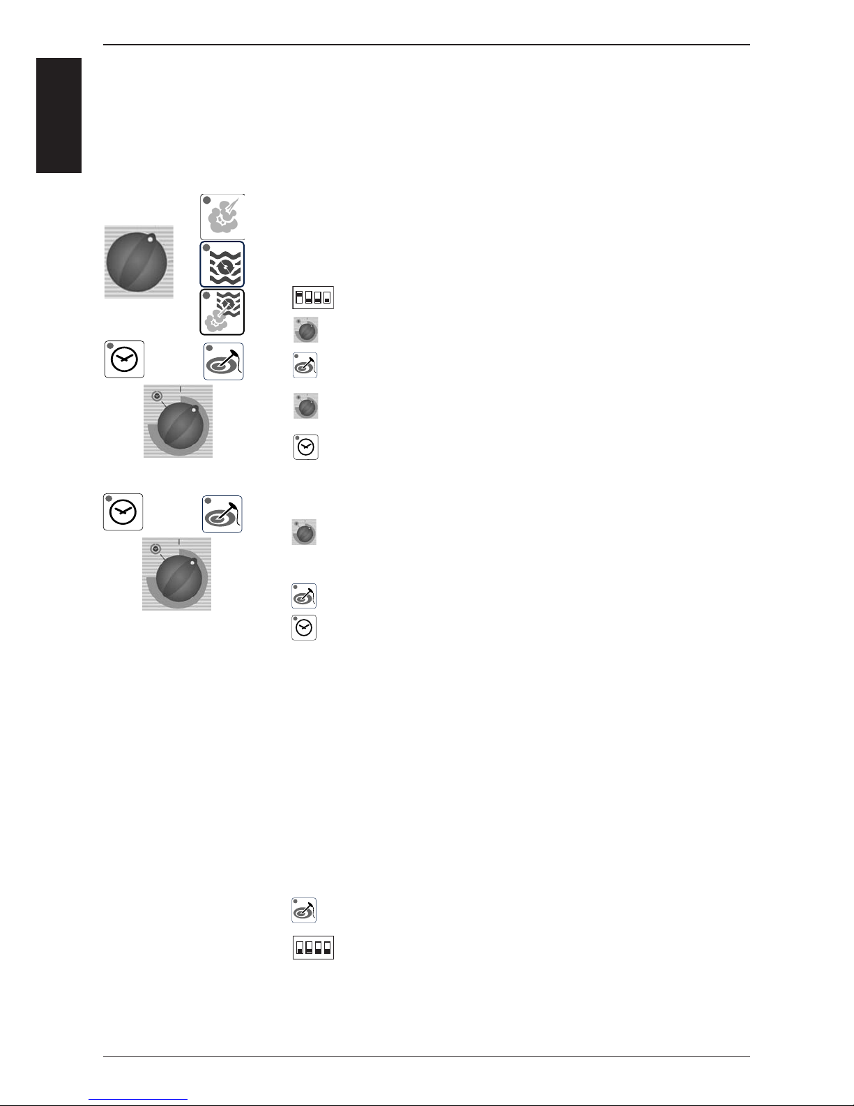
Open cabinet door
Select any mode
Open control panel
Set DIP switch 1 on PCB to „ON“ position
With timer dial select: „SE“ = Settings
Activate „Settings“ by pressing core temperature key; display
changes to „SE1“
With timer dial select: SE9
Activate position SE9 „blower motor steam MIN“ rpm with timer
key
Timer display shows stored value from EEPROM, i.e. 6250
While pressing timer key blower speed can be adjusted with timer
dial by + / -10%
Note: Adjust steps in increments of 60rpm only!
Changed rpm will be shown in timer display.
Confi rm new rpm setting with core temperature key
(keep timer key pressed)
Release timer key
Repeat steps F) - J) at SE10 „blower motor steam Start“ rpm
and at SE11 „blower motor steam MAX“ rpm“
Adjust steps in increments of 60rpm only!
Repeat steps F) - J) at
SE12 „blower motor hot air, top MIN“ rpm,
SE13 „blower motor hot air, top Start“ rpm, and
SE14 „blower motor hot air, top MAX“ rpm.
Adjust steps in increments of 60rpm only!
CM 201 and 202: Repeat steps F) - J) at
SE15 „blower motor hot air, bottom MIN“ rpm,
SE16 „blower motor hot air, bottom Start“ rpm, and
SE17 „blower motor hot air, bottom MAX“ rpm.
Adjust steps in increments of 60rpm only!
De-activate selected package by pressing core temperature key;
To exit service program set DIP switch 1 to „OFF“ position
To store the new blower speed setting the unit must be switched
OFF and ON again.
Perform fl ue gas analysis in function test at F21, F24, F27
as well as the check of CO2 values at F19, F22, F25
1
234
on
1
234
on
Page 35
-35-
S
S
C
C
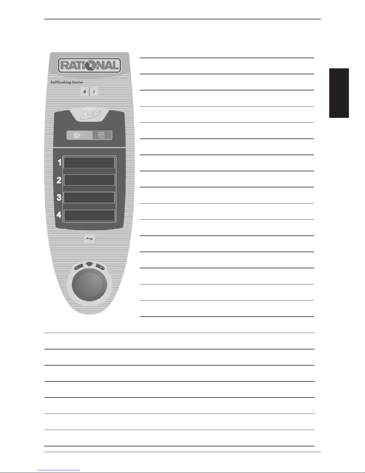
SCC Control Panel
Notes:
Page 36
-36-
S
S
C
C
1
2
3
4
1
2
3
4
1
2
3
4
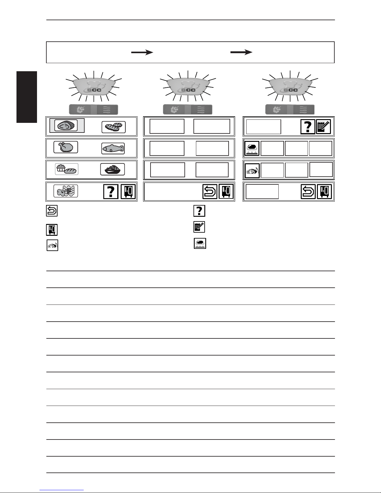
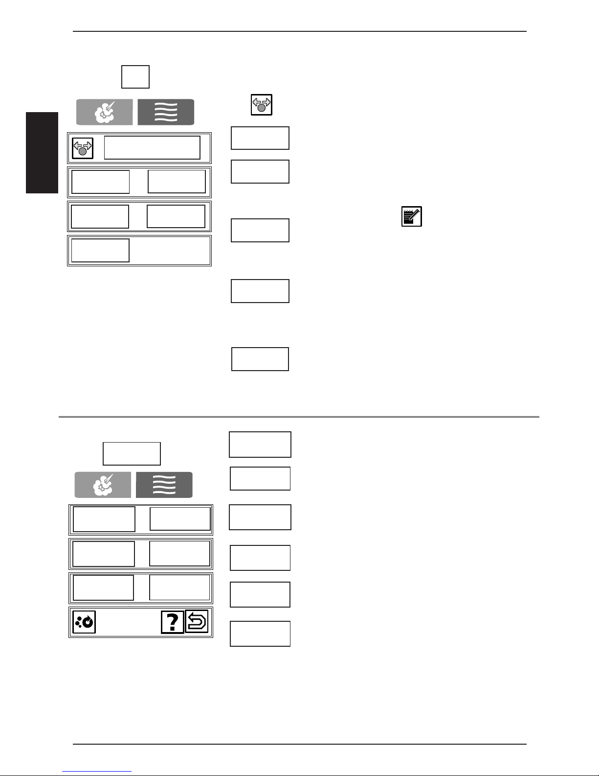
Back to previous level help guide line for selected setting
CleanJet, HACCP, Delta T, E1/2 Store selected setting
Start time, CDS, Descaling, Settings
Selection of core temperature Searing
Notes:
SelfCooking Control
Mode - Level 1
SelfCooking Control
Mode - Level 2
SelfCooking Control
Mode - Level 3
Up to Software version SCC 01-07-12 only!
Universal
roasting
Roasting with
crackling
Soft
roasting
Soft
cooking
Overnight
cooking
Overnight
roasting
Low
Overnight
roasting
rare
well
done
preheat
High
Page 37
-37-
S
S
C
C
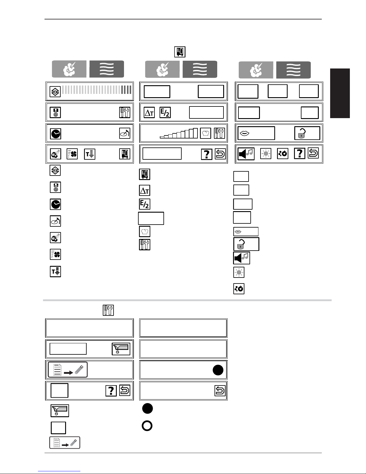
Combi Steamer Mode Functions Settings
1
2
3
4
1
2
3
4
1
2
3
4
0% 10% 20% 30% 40% 50% 60% 70% 80% 90% 100%
200°C
Duration
CDS
CleanJet
HACCP
Start time
Settings
10:24
english
am/pm
24 h
h:m
m:s
08/22/03
22.08.03
°C / °F
Prog
1
2
3
4
1
2
3
4
Service Typ
HACCP
Prog
english
h:m
m:s
am/pm
24 h
08/22/03
22.08.03
°C / °F
Service Info No: E11SE0503200......... Service Info: Display of
pending service faults
Descaling SW: SCC - 01 - 07 - 08
Mod: SCC_101
English
empty steam generator humidity emergency control active
(Door must be open!)
humidity emergency control was active since last switch ON
Display Software version (will not be displayed when in „dry heat mode“)
Download of service data to stick.Set DIP-switch 1 to “on” (=activation of diagnostic program).
Afterwards touch function key and then service key.
Typ
Typ
Setting of Humidity
Setting of cabinet
temperature
Setting of time
Setting of
core temperature
Moistening
Setting of
fan speed
Cool Down
Setting of : time, Date,
time format, °C/°F etc.
Delta -T cooking
1/2 Energy
HACCP Protokol
Telephone Chef-Line
Service
Setting of time format
Setting of time laps
Setting of date format
Setting of °C/°F
Setting of language
default 12345, SU: ttreu
Setting of buzzer sound
Setting of display intensity
Setting of CleanJet prompting
(only active when frame is red)
Info
Info
Up to Software version SCC 01-07-12 only!
Page 38
-38-
S
S
C
C
1
2
3
4
1
2
3
4
1
2
3
4
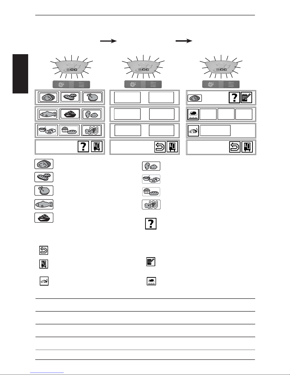
Large roast Potato product
Pan fries Egg dishes/Desserts
Poultry Bakery products
Fish Finishing
Side dishes Help: guide line for selected setting;
practical hints for product to be used
in the respective SCC cooking process
Back to previous level
CleanJet, HACCP, Delta T, E1/2 Store selected setting
Start time, CDS, Descaling, Settings
Selection of core temperature Searing
Notes:
SelfCooking Control
Mode - Level 1
SelfCooking Control
Mode - Level 2
SelfCooking Control
Mode - Level 3
roast braise
roast with
crackling
gentle
roasting
gentle
cooking
medium
62°C
close
door
This display since Software version SCC 02-01-01 only!
overnight
roasting
13:45
overnight
roasting
13:45
Page 39
-39-
S
S
C
C
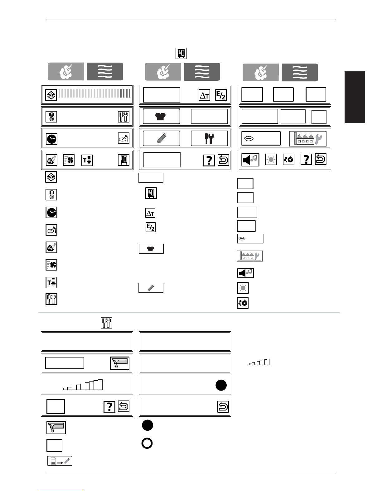
Setting of Humidity
Setting of cabinet
temperature
Setting of time
Setting of
core temperature
Moistening
Setting of fan speed
(lowest level=intermittent)
Cool Down
Service key
(after setting dip switch #1)
Combi Steamer Mode Functions Settings
1
2
3
4
1
2
3
4
1
2
3
4
0% 10% 20% 30% 40% 50% 60% 70% 80% 90% 100%
200°C
Duration
10:24
english
am/pm
24 h
h:m
m:s
1
2
3
4
1
2
3
4
Service Typ
english
h:m
m:s
am/pm
24 h
08/22/03
22.08.03
°C /
°F
Service Info No: E11SE0503200......... Service Info: Display of
pending service faults
Descaling SW: SCC - 01 - 07 - 08 Scale level of steam gen.
Mod: SCC_101
English
empty steam generator humidity emergency control active
(Door must be open!)
humidity emergency control was active since last switch ON
Display Software version (will not be displayed when in „dry heat mode“)
Download of service data to stick.Set DIP-switch 1 to “on” (=activation of diagnostic program).
Afterwards touch function key and then service key.
Typ
Typ
CleanJet programs
Function level
Delta -T cooking
1/2 Energy
Telephone Chef-Line
delete all programs, program lock, buzzer setting,
time setting
Data download (upload):
Customer programs
HACCP
Service data
Setting of time format
Setting of time laps
Setting of date format
Setting of °C/°F
Setting of language
reset to factory setting
english, °C, buzzer perm.,
buzzer,
Setting of buzzer sound
Setting of display intensity
settings
start time
CleanJet
CleanJet
IP
10/22/06
22.10.06
°C /
°F
Info
This display since Software version SCC 02-01-01 only!
CDS
CDS
Page 40
-40-
S
S
C
C
1
2
3
4
1
2
3
4
delete
Prog
new
level
control
copy
change
Clean manual
CleanJet
select program name with central dial
give program name (blank - between _ and @
existing SCC process or program can be
copied and get an index number, i.e. 1; name
can be edited and changed;
Change parameter and / or cooking mode of
program in a non-active program;
confi rm change by:
selected program fl ashes; confi rm delete by
pressing again
1. Give program name
2. Store
3. select mode, temperature, time (in minutes and
seconds) or core temperature,
4. Second program with identical mode and
temperature, but different time can be stored
and selected alternating after pre-heating;
rinse with water only; cabinet will be dried out;
rinse with 1 rinse tab for cleaning after steaming
rinse with 1 cleaner tab for cleaning in between
cooking cycles; no drying of cabinet;
Cleaning of light soiling with drying of cabinet
Cleaning of medium soiling with drying of cabinet
Cleaning of strong soiling with drying of cabinet
Note:
Reduce number of detergent tabs when
too much foam is visible;
Check direction of water jet inside cabinet
when timer is counting up;
new
copy
change
delete
level
control
rinse
without tabs
rinse
interim
cleaning
light
medium
strong
CleanJet
rinse
without tabs
rinse
interim
cleaning
light
medium
strong
Page 41

-41-
S
S
C
C
Notes:
Page 42
-42-
S
S
C
C
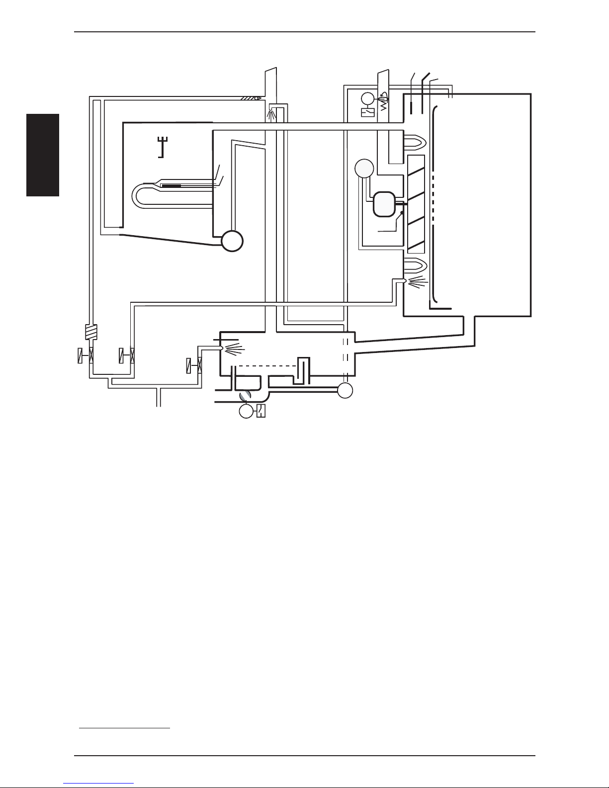
B1
B6
F4
P1
M3
S4
M4
M6
S11
Y
1
Y2
Y3
B2
M1
S2
M7
S12
B4
B5
F3
B1 Thermocouple interior cabinet
B2 Thermocouple quenching
B4 Thermocouple humidity
B5 Thermocouple steam generator (preheat, 180°C (356°F) max)
B6-B11 Thermocouples core temperature
F3 Safety thermostat steam generator 160°C (320°F)
F4 Safety thermostat interior cabinet 360°C (680°F)
Y1 Solenoid valve fi lling
Y2 Solenoid valve quenching
Y3 Solenoid valve moistening
M1 Fan motor bottom
M3 Humidity fl ap motor
M4 SC-pump
M6 CleanJet pump
M7 Motor drain valve / ball valve
S2 Level electrode
S4 Micro switch humidity motor
S11 CDS sensor
S12 Micro switch drain valve
P1 Pressure sensor humidity
SCC 201/202 only:
M2 Fan motor top with jumper (fl oor units only)
SCC Electric from 04-2004
Page 43

-43-
S
S
C
C
Notes:
Page 44
-44-
S
S
C
C
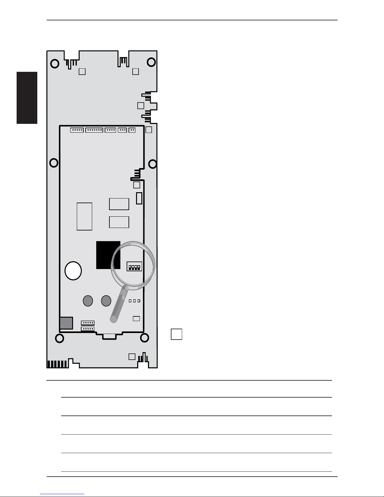
X 7X 8
X 1
X 51
X 54
X 53
X 09
X 10
X 5X 2X 6X 4
X 50
A2 SCC pcb
A3 Add On pcb
X 52
X 2
3V
ON
LED
1 2 3
X 3
RS 232
Battery
X 12
X 11
X7 200 - 240V input to I/0 Switch
X8 Buzzer
X12 Level electrode
X11 Humidity fl ap motor / Micro switch
Add on X1 P1 pressure sensor
Add on X2 B6-11 thermocouples
core temperature
Add on X3 B1 thermocouple interior cabinet
Add on X4 B2 thermocouple quenching
Add on X5 B4 thermocouple humidity
Add on X6 B5 thermocouple steam generator
Add on X50 External EEPROM
Add on X51 BUS interface
and power supply for cpu from I/O pcb
Add on X52 RS232 interface
Add on X53 USB interface (only until November 2005)
Add on X54 USB interface
Add on X09 Central dial
X10 Power suply for display 2,5 - 0 - 2,5V
(X10 indicated as X1 on pcb layout)
X2 Free
Counting sequence
Note: LED code: SCC PCB
Green LED on - ok;
Red LED blinks 1x during re-booting when switching on - ok
Green LED - off: Bus cable defective; CPU defective; I/O pcb or transformer defective
Red LED on: CPU defective
Red LED doesn‘t blink during re-booting when switching on - CPU defective
SCC Operator pcb (42.00.002)
1
1
1
1
11
1
Page 45
-45-
S
S
C
C
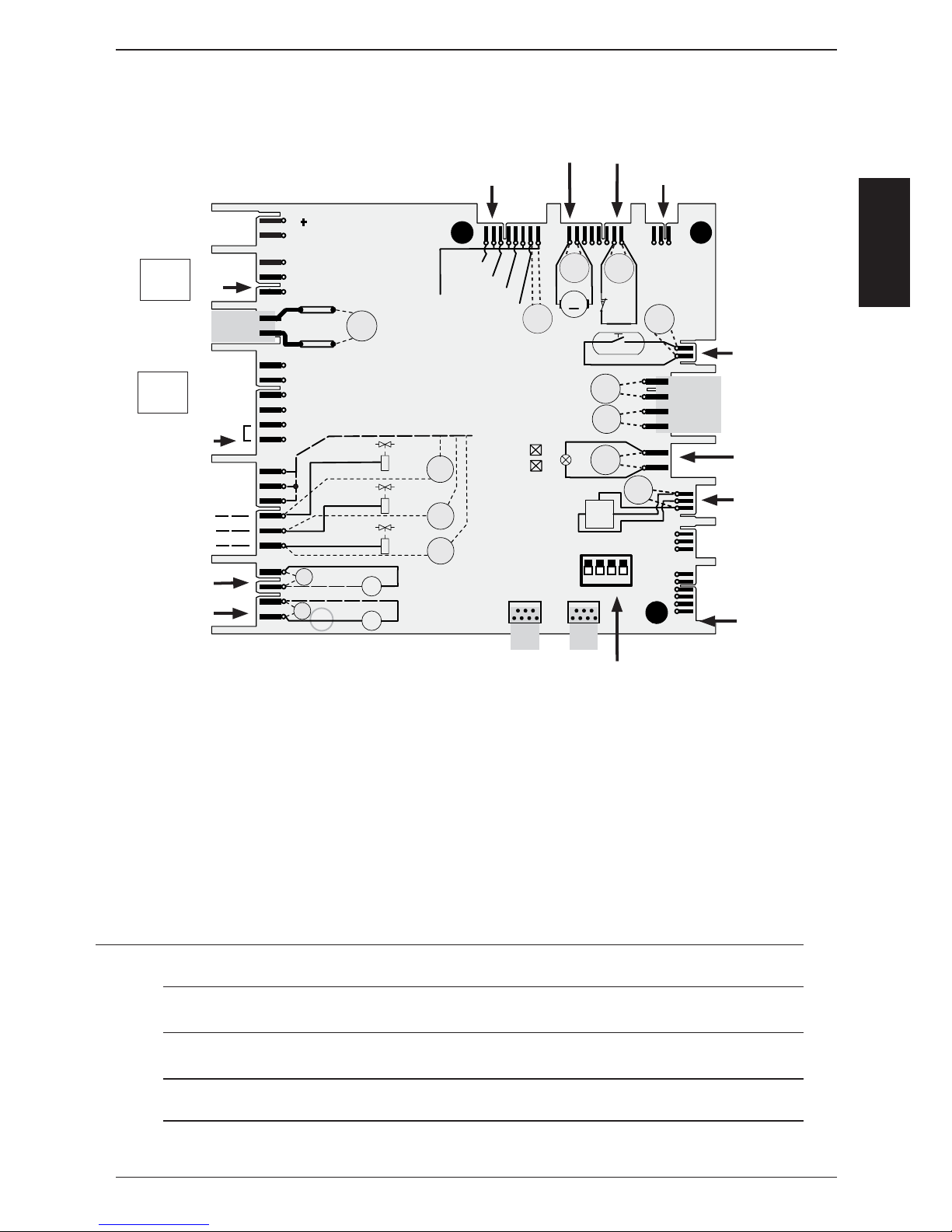
UltraventVent .
230V
input
Energy optimising
Sicotronic
Y1 fi lling
Y2 quenching
Y3 moistening
SC pump
CleanJet pump
Measuring points I/O PCB SCC (40.00.049)
Wires of pcb edge connectors are pointing to component side of pcb!
Motor drain valve Micro switch drain valve
12 V DC SSR
SSR puls (USA version)
all DIP must be OFF
S3
T1
K1:L1
F2: N
230 V
GND
IN
OUT
CDS-HALL
S12
M7
M
+
_
16 V DC
11,5 V AC
Y1
A1
A2
A1
A2
Y3
A1
A2
M4
M
~
M6
M
~
12 V DC
12 V AC
12 V DC
H1
11, 5 V
AC
Y1
230 V
Y2
230 V
Y3
230 V
230 V
230 V
N
BUS
BUS
+ 12V
SSR1: A-
SSR1: B-
SSR2: A-
SSR2: B-
N
Y2
12 V DC
12 V DC
2A T
2A T
LED 1
LED 2
X6.1
X 24.1
X 25.1
X 26.1
X 27.1
X 14.1
X 13.1
X 15.1
X 17.1
X 16.1
X 23.1
X 21.1
X 20.1
X 19.1
X 18.1
ON
1
2
34
Door contact
11,5V - 12V
from Transformer
Cabinet light
CDS sensor
Counting sequence
1: Ultravent connection used for Ultravent without Bus connection only!
2: Energy optimizing plug with link on 5-6 used only on I/O pcb with 6 relais card!
Please refer to Technical Info 16-2005
Note: LED code: I/O PCB
Green LED on - ok;
Yellow LED blinks during re-booting but is off during operation - ok
Yellow LED blinks always: Set DIP switches to OFF position; Bus cable defective;
Green LED off: I/O pcb defective; transformer defective
1
2
Page 46
-46-
S
S
C
C
Motor for SCC / CM
Jumper 40.01.581 is used on fl oor model 201 and 202 for top position motor only!
Jumper is not used on models 61 - 102 with one motor only! (Service 34 will be shown!)
LED
Jumper
Reason
1x Motor doesn’t start, no changing
signal from hallsensor
2x Voltage too low on motor pcb
3x Voltage too high on motor pcb
4x rpm measurement defective
5x Motor pcb temperature >105°C
6x Supply voltage <80V
7x Motor pcb defective
8x Motor pcb defective
LED code fan motor SCC and CM from 04/2004
Remedy
Check for motor blockage or change motor.
Check supply voltage or
change motor.
Check supply voltage or
change motor.
Change motor.
Check cooling system (cooling fan, air
intake fi lter), otherwise change motor
Check power supply
(F1-F2)
Change motor.
Change motor.
Page 47

-47-
S
S
C
C
Notes:
Page 48
-48-
S
S
C
C
Mode: Wet heat (98-103°C (208-218°F),
set temperature)
Function step
Select Wet heat
(Temp 98-103°C (208-218°F))
Select time or core temperature
Close cabinet door
Check water level inside steam
generator
Preheat steam generator,
if B5 is below 85°C (185°F);
Timer starts after successful preheating
Steam production up to saturation in
cabinet
Adding of Hot Air from 70°C (158°F)
possible, if 70% humidity reached
Quenching (set to 70°C/158°F)
Responsible sensor
Reed switch S3
Level electrode S2 inside Steam Generator
Thermocouple B5 inside
Steam Generator
Logic on PCB
Pressure sensor P1
Thermocouple B4
rpm motor via BUS
Cabinet sensor B1
Thermocouple B2
Signal
Door open: 12VDC X27:(1-2)
Door closed: 0VDC X27:(1-2)
X12:(1-4) > 2VAC => no water
X12:(1-4) ~ 0VAC => water
SSR active: 12VDC X24:(1-2)+(5-6)
SSR not active: 0VDC X24:(1-2)+(5-6)
Gas unit: Bus signal
SSR active: 12VDC X24:(1-2)+(5-6)
SSR not active: 0VDC X24:(1-2)+(5-6)
Gas unit: Bus signal
SSR active: 12VDC X24:(7-8)+(3-4)
SSR not active: 0VDC X24:(7-8)+(3-4)
Gas unit: Bus signal
B2 above set Temp.: Y2 active
B2 below set Temp.: Y2 not active
Remark
Solenoid Y1 energizes when
no water, 230VAC, X19:(1-4)
Heating off,
if B5 > 180°C (356°F)
Blinking dot on timer display
Decision of Hot Air supply by
PCB logic
Y2 act.: 230VAC, X19:(2-5)
Y2 not act.: 0VAC, X19:(2-5)
1
2
3
4
5
6
7
8
9
Additional functions possible: 4 Fan speeds (Standard = Level 4), pulsed fan wheel,
½ Energy, HACCP output, ∆T
Note:
Steam heating only active when humidity fl ap (S4) is in closed position!
SCC Units: Sequence of Events
Page 49
-49-
S
S
C
C
Mode: Low temperature steam;
(30-97°C (85-207°F), set temperature)
Function step
Select Wet heat
(Temp 30-97°C (85-207°F)
Select time or core temperature
Close cabinet door
Check water level inside steam
generator
Preheat steam generator,
if B5 is below 85°C (185°F);
Timer starts after successful preheating
Steam supply until set temperature inside cabinet is reached
Adding of Hot Air from 93°C (200°F)
possible (only 50%)
Quenching (set to 70°C/158°F)
Responsible sensor
Reed switch S3
Level electrode S2 inside Steam Generator
Thermocouple B5 inside
Steam Generator
Logic on PCB
Cabinet sensor B1
Cabinet sensor B1
Thermocouple B2
Signal
Door open: 12VDC X27:(1-2)
Door closed: 0VDC X27:(1-2)
X12:(1-4) > 2VAC => no water
X12:(1-4) ~ 0VAC => water
SSR active: 12VDC X24:(1-2)+(5-6)
SSR not active: 0VDC X24:(1-2)+(5-6)
Gas unit: Bus signal
SSR active: 12VDC X24:(1-2)+(5-6)
SSR not active: 0VDC X24:(1-2)+(5-6)
Gas unit: Bus signal
SSR active: 12VDC X24:(7-8)+(3-4)
SSR not active: 0VDC X24:(7-8)+(3-4)
Gas unit: Bus signal
B2 above set Temp.: Y2 active
B2 below set Temp.: Y2 not active
Remark
Solenoid Y1 energizes when no
water, 230VAC, X19:(1-4)
Heating off,
if B5 > 180°C (356°F)
Blinking dot on timer display
Decision of Hot Air supply by
PCB logic
Y2 act.: 230VAC, X19:(2-5)
Y2 not act.: 0VAC, X19:(2-5)
1
2
3
4
5
6
7
8
9
Note:
Steam heating only active when humidity fl ap (S4) is in closed position!
Below 98°C fan at lowest speed when no energy required for longer than 2 minutes.
SCC Units: Sequence of Events
Additional functions possible: 4 Fan speeds (Standard = Level 4), pulsed fan wheel,
½ Energy, HACCP output, ∆T
Page 50
-50-
S
S
C
C
Mode: Forced Steam104-130°C
(219-266°F), set temperature)
Function step
Select Wet heat
(Temp 104-130°C (219-266°F))
Select time or core temperature
Close cabinet door
Check water level inside steam
generator
Preheat steam generator,
if B5 is below 85°C (185°F);
Timer starts after successful preheating
Steam production up to saturation in
cabinet
Adding of Hot Air if 85% humidity
reached
Quenching (set to 70°C/158°F)
Responsible sensor
Reed switch S3
Level electrode S2 inside Steam Generator
Thermocouple B5 inside
Steam Generator
Logic on PCB
Pressure sensor P1
Thermocouple B4
rpm motor via BUS
Cabinet sensor B1
Thermocouple B2
Signal
Door open: 12VDC X27:(1-2)
Door closed: 0VDC X27:(1-2)
X12:(1-4) > 2VAC => no water
X12:(1-4) ~ 0VAC => water
SSR active: 12VDC X24:(1-2)+(5-6)
SSR not active: 0VDC X24:(1-2)+(5-6)
Gas unit: Bus signal
SSR active: 12VDC X24:(1-2)+(5-6)
SSR not active: 0VDC X24:(1-2)+(5-6)
Gas unit: Bus signal
SSR active: 12VDC X24:(7-8)+(3-4)
SSR not active: 0VDC X24:(7-8)+(3-4)
Gas unit: Bus signal
B2 above set Temp.: Y2 active
B2 below set Temp.: Y2 not active
Remark
Solenoid Y1 energizes when no
water, 230VAC, X19:(1-4)
Heating off,
if B5 > 180°C (356°F)
Blinking dot on timer display
Decision of Hot Air supply by
PCB logic
Y2 act.: 230VAC, X19:(2-5)
Y2 not act.: 0VAC, X19:(2-5)
1
2
3
4
5
6
7
8
9
Note:
Steam heating only active when humidity fl ap (S4) is in closed position!
SCC Units: Sequence of Events
Additional functions possible: 4 Fan speeds (Standard = Level 4), pulsed fan wheel,
½ Energy, HACCP output, ∆T
Page 51
-51-
S
S
C
C
Mode: Combi Steam 141-300°C
(286-572°F), set temp.
Function step
Select Wet and Dry heat
(Temp 141-300°C (286-572°F))
Select time or core temperature
Close cabinet door
Check water level inside steam generator
Preheat steam generator,
if B5 is below 85°C (185°F);
Timer starts after successful preheating
Heat up cabinet with Hot Air until set
temperature.
Priority Hot Air
Adding of steam up to set steam saturation
Quenching (set to 70°C/158°F)
Responsible sensor
Reed switch S3
Level electrode S2 inside Steam Generator
Thermocouple B5 inside
Steam Generator
Logic on PCB
Cabinet sensor B1
Pressure sensor P1
Thermocouple B4
rpm motor via BUS
Thermocouple B2
Signal
Door open: 12VDC X27:(1-2)
Door closed: 0VDC X27:(1-2)
X12:(1-4) > 2VAC => no water
X12:(1-4) ~ 0VAC => water
SSR active: 12VDC X24:(1-2)+(5-6)
SSR not active: 0VDC X24:(1-2)+(5-6)
Gas unit: Bus signal
SSR active: 12VDC X24:(7-8)+(3-4)
SSR not active: 0VDC X24:(7-8)+(3-4)
Gas unit: Bus signal
SSR active: 12VDC X24:(1-2)+(5-6)
SSR not active: 0VDC X24:(1-2)+(5-6)
Gas unit: Bus signal
B2 above set Temp.: Y2 active
B2 below set Temp.: Y2 not active
Remark
Solenoid Y1 energizes when
no water, 230VAC, X19:(1-4)
Heating off,
if B5 > 180°C (356°F)
Blinking dot on timer display
Y2 act.: 230VAC, X19:(2-5)
Y2 not act.: 0VAC, X19:(2-5)
1
2
3
4
5
6
7
8
9
Note:
Steam heating only active when humidity fl ap (S4) is in closed position!
SCC Units: Sequence of Events
Additional functions possible: 4 Fan speeds (Standard = Level 4), pulsed fan wheel,
½ Energy, HACCP output, ∆T, manual moistening
Page 52
-52-
S
S
C
C
Mode: Finishing
(30°-140°C (85-284°F), set Temp.
Function step
Select Wet and Dry heat
(Temp. 30-140°C, 85-284°F)
Select time or core temperature
Close cabinet door
Check water level inside steam generator
Preheat steam generator,
if B5 is below 85°C (185°F);
Timer starts after successful preheating
Steam supply up to set humidity
Electric: 8sec on / off
Gas: 20 sec on / off
Hot air supply up to set temperature
Electric: 8 sec on / off
Gas: 20 sec on / off
Quenching (set to 70°C/158°F)
Responsible sensor
Reed switch S3
Level electrode S2 inside Steam Generator
Thermocouple B5 inside
Steam Generator
Logic on PCB
Pressure sensor P1
Thermocouple B4
rpm motor via BUS
Cabinet sensor B1
Thermocouple B2
Signal
Door open: 12VDC X27:(1-2)
Door closed: 0VDC X27:(1-2)
X12:(1-4) > 2VAC => no water
X12:(1-4) ~ 0VAC => water
SSR active: 12VDC X24:(1-2)+(5-6)
SSR not active: 0VDC X24:(1-2)+(5-6)
Gas unit: Bus signal
SSR active: 12VDC X24:(1-2)+(5-6)
SSR not active: 0VDC X24:(1-2)+(5-6)
Gas unit: Bus signal
SSR active: 12VDC X24:(7-8)+(3-4)
SSR not active: 0VDC X24:(7-8)+(3-4)
Gas unit: Bus signal
B2 above set Temp.: Y2 active
B2 below set Temp.: Y2 not active
Remark
Solenoid Y1 energizes when
no water, 230VAC, X19:(1-4)
Heating off,
if B5 > 180°C (356°F)
Blinking dot on timer display
Y2 act.: 230VAC, X19:(2-5)
Y2 not act.: 0VAC, X19:(2-5)
1
2
3
4
5
6
7
8
9
Note:
Steam heating only active when humidity fl ap (S4) is in closed position!
Below 98°C fan at lowest speed when no energy required for longer than 2 minutes.
SCC Units: Sequence of Events
NOTE: For initial heating of cabinet => alternately energy supply of Steam and Hot Air (Electric: 8 seconds each; Gas:20 seconds each)
Additional functions possible: 4 Fan speeds (Standard = Level 4), pulsed fan wheel,
½ Energy, HACCP output, ∆T, manual moistening
Page 53
-53-
S
S
C
C
Mode: Dry heat 30°-300°C
(86-572°F), set Temp.
Function step
Select Dry heat
Temp. 30-300°C (86-572°F)
Select time or core temperature
Close cabinet door
Timer starts counting down
Heat up cabinet with Hot Air until set
temperature
Quenching (set to 90°C/158°F)
Responsible sensor
Reed switch S3
Logic on PCB
Cabinet sensor B1
Thermocouple B2
Signal
Door open: 12VDC X27:(1-2)
Door closed: 0VDC X27:(1-2)
SSR active: 12VDC X24:(7-8)+(3-4)
SSR not active: 0VDC X24:(7-8)+(3-4)
B2 above set Temp.: Y2 active
B2 below set Temp.: Y2 not active
Remark
Blinking dot on timer display
Y2 act.: 230VAC, X19:(2-5)
Y2 not act.: 0VAC, X19:(2-5)
1
2
3
4
5
6
Humidity control permanently checks the humidity coming from the product.
If needed the humidity fl ap is being opened in order to reduce the actual humidity
to the set value.
SCC Electric: Sequence of Events
Additional functions possible: 4 Fan speeds (Standard = Level 4), pulsed fan wheel,
½ Energy, HACCP output, ∆T, manual moistening
Note:
Below 98°C fan at lowest speed when no energy required for longer than 2 minutes.
Page 54
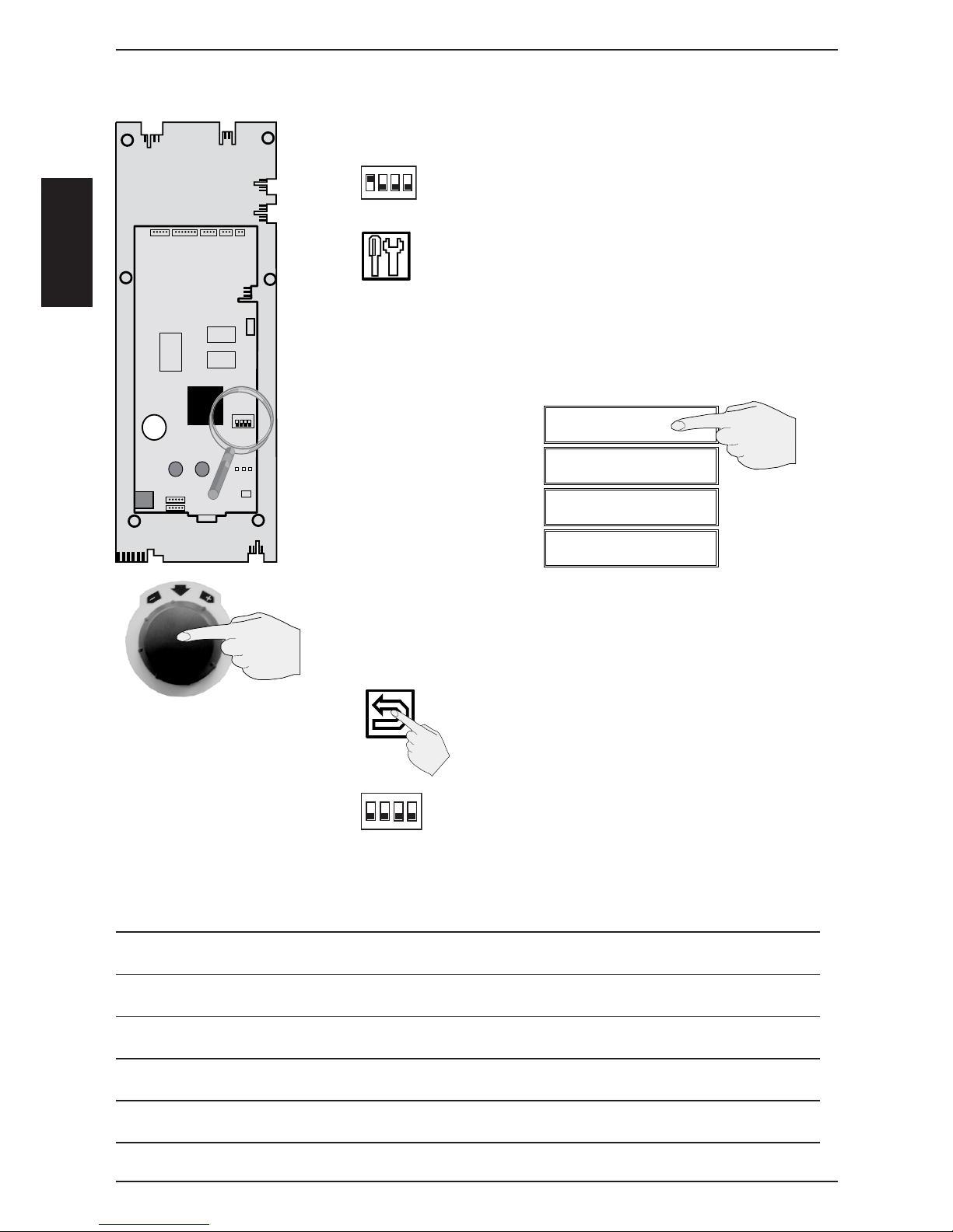
-54-
S
S
C
C
1
2
3
4
Switch on unit
Set DIP 1 on operator PCB to „“ON““ position
Press service key
On the displays the following available
Service - modules will be shown
Window 1 Diagnostic
Window 2 Running Times
Window 3 Basic Settings
Window 4 Function Test
Activate selected service module by push on display or push
on central dial
Deactivate selected service module
by pushing on “return“ symbol
Set DIP 1 on operator PCB to “OFF“ position
to deactivate Service level
Starting with software version 01-07-02 gas related
information is not shown on electric units!
Service level SCC
X 7X 8
X 1
X 51
X 54
X 53
X 09
X 10
X 5X 2X 6X 4
X 50
A2 SCC pcb
A3 Add On pcb
X 52
X 2
3V
ON
LED
1 2 3
X 3
RS 232
Battery
X 12
X 11
A)
B)
C)
D)
E)
F)
G)
1
234
on
1
234
on
Notes:
Page 55

-55-
S
S
C
C
Notes:
Page 56
-56-
S
S
C
C
Diagnostic
Running Times
Basic Settings
Function Test
1 - Diagnostic
Cabinet
B1
130°C 345°C
act max
160°C
32 min
SCC Diagnostic Mode overview
DIAGNOSTIC
1 - Cabinet B1
2 - Quenching B2
3 - Not used
4 - Humidity B4
5 - Steam Generator B5
6-11 - Core Temp B6-11
12 - Temperature
13 - Level Electrode S2
14 - Door Contact S3
15 - Clima
16 - Clima Status
17 - Clima Motor
18 - Hot Air
19 - Steam
20 - SC Automatic
21 - Volume
22 - M6 CleanJet pump
Y2 Quenching solenoid
23 - M7 Drain valve
S12 Micro switch
24 - Service Error History
25 - Gas Error History
1
2
3
4
1
2
3
4
1
2
3
4
Reset
Page 57
-57-
S
S
C
C
SCC Diagnostic Mode
1
2
3
4
1
2
3
4
1
2
3
4
1
2
3
4
1
2
3
4
1
2
3
4
1
2
3
4
1
2
3
4
1
2
3
4
1 - DIAGNOSTIC
Cabinet B1
130°C 345°C
act max“
- Temp. range: -30 - 340°C
(-22 - 644°F)
- 900°C (655°C until SW version
01-07-08) broken thermocouple
or loose plug
- to reset max value press RESET
4 - DIAGNOSTIC
Humidity B4
130°C 345°C
act max“
- Temp. range: -30 - 340°C
(-22 - 644°F)
- 900°C (655°C until SW version
01-07-08) broken thermocouple or
loose plug
- to reset max value press RESET
12 - DIAGNOSTIC
Temperature PCB
130°C 345°C
act max“
- Temp. range: -30 - 85°C (-22 -
185°F)
- to reset max value press RESET
(keep pressed until value is
re-seted)
- above 75°C (167°F) warning
on window #4 => clean air fi lter
-
above 85°C (185°F) => Service 29
3 - DIAGNOSTIC
Not used
B3
900°C 900°C
B3 not used. No function
6 - 11 - DIAGNOSTIC
Core Temp B6 - B11
130°C 305°C
act max“
- Temp. range: -30 - 340°C (-22
- 644°F)
- 900°C (655°C until SW version
01-07-08) broken thermocouple
or loose plug
- to reset max value press RESET
14 - DIAGNOSTIC
Door Contact
S3
1 - 0
1 - door closed
0 - door open
2 - DIAGNOSTIC
Quenching B2
70°C 95°C
act max“
- Temp. range: -30 - 340°C (-22
- 644°F)
- 900°C (655°C until SW version
01-07-08) broken thermocouple or
loose plug
- to reset max value press RESET
5 - DIAGNOSTIC
Steam Generator B5
104°C 115°C
act max“
- Temp. range: -30 - 340°C (-22
- 644°F)
- 900°C (655°C until SW version
01-07-08) broken thermocouple or
loose plug
- to reset max value press RESET
13 - DIAGNOSTIC
Level Electrode S2
S2 1 - 0
Y1 0 - 1
S2 = 1 => Water level reached
S2 = 0 => Water level too low
Y1 = 0 => Filling solenoid not active
Y1 = 1 => Filling solenoid active
Reset
Reset
Reset
Reset Reset
Reset
Reset
Page 58
-58-
S
S
C
C
15 - DIAGNOSTIC
Clima
P1 - B4 - RPM
Default out
0,48V 2,24V
B4 85% rpm
145°C 1850
Default: 0,4-0,55V
At standard speed:
Out ca. 1,3 - 1,6V Combi 200°C
(392°F)
Out ca. 1,5 - 1,9V Steam 100°C
(212°F)
Out ca. 2.5 - 3,0V Hot air 60°C
(140°F)
18 - DIAGNOSTIC
Hot Air
0% 50% 100%
21 - DIAGNOSTIC
Volume
Calc 3,6l
check
Fill Norm
3,2l 4,2l
Window 3: Release volume
Window 4, left side:
Filling volume during last SC-Automatic. As of SW version 01-07-04
the fi lling progress can be observed.
Window 4, right side: nominal fi lling
volume with a clean steam tank
16 - DIAGNOSTIC
Clima Status
Cal speed1 Error
xxxrpm --------
Dry Wet Combi
xxxx xxxx xxxx
- Display of calibration values rela tive to the different motor speeds
and unit size;
- Normal values between
72000-110000
19 - DIAGNOSTIC
Steam
0% 50% 100%
22 - DIAGNOSTIC
M6 CleanJet Pump
Y2 Quenching solenoid
M6 0-1
Y2 0-1
As of SW Version 01-07-04
service mode can be selected
while CleanJet mode is active.
17 - DIAGNOSTIC
Clima Motor
M3 1-0
S4 0-1
No steam production,
when S4 is „0“ => open!
20 - DIAGNOSTIC
SC-Automatic
53min
45sec 60min
Window 3:
- 53min since last SC -automatic
- Pressing Test => time will be set
to set time plus 1 minute
Window 4:
- 45sec: Preset SC-duration (20-90sec)
- 60min: Preset SC-time (20-90min)
23 - DIAGNOSTIC
M7 Drain valve motor
S12 micro switch
M7 0-1
S12 1-0
As of SW Version 01-07-04
service mode can be selected
while CleanJet mode is active.
1
2
3
4
1
2
3
4
1
2
3
4
1
2
3
4
1
2
3
4
1
2
3
4
1
2
3
4
1
2
3
4
1
2
3
4
Test
SCC Diagnostic Mode
Page 59
-59-
S
S
C
C
Notes: Starting with Software version 01-07-09 the entire information of the service level can
be downloaded to memory stick when DIP switch 1 is set to „1“.
1
2
3
4
1
2
3
4
25 - DIAGNOSTIC
Gas error history
Gas 1
0: 09:10.05 9:17 32
- since software version 01-07-09
Indication of the last 16 stored ig
nition box error messages including
date and time.
0= ignition box top
1= ignition box bottom
24 - DIAGNOSTIC
Service error history
i.e. (1) Service 10
- since software version 01-07-09
Indication of the last 10 stored
service error messages
(see Service error message list
page61-62)
Indication of ignition box error messages (1-32 is shown to the operator as „Reset“):
1 Hot air or Steam no gas, gas valve or electrode defective
14 Hot air gas valve controll, change ignition box
19 Hot air no fl ame because fl ame current is too low
check burner setting, fl ame current, ignition cable and plug
20 Hot air wrong or no rpm signal from gas blower
check gas blower, power supply gas blower and control harness
of gas blower
22 Hot air no fl ame after 5 ignition sequences
no gas, gas valve or electrode defective
24 Steam gas valve controll, change ignition box
29 Steam no fl ame because fl ame current is too low
check burner setting, fl ame current, ignition cable and plug
30 Steam wrong or no rpm signal from gas blower
check gas blower, power supply gas blower and control harness
of gas blower
32 Steam no fl ame after 5 ignition sequences
no gas, gas valve or electrode defective
Possible failure in case of „Service 32“
33, 36 Change ignition box
35 Check frequency of main
39 Hot air Check burner setting, ignition electrode and distance,
and fl ame current
40 Hot air Check ignition cable
42 Steam Check burner setting, ignition electrode and distance,
and fl ame current
43 Steam Check ignition cable
Is shown on display „Change polarity“
34 Change polarity of mains
All other numbers (2-13, 15-18, 21, 23, 25-28, 31): change ignition box
SCC Diagnostic Mode
Page 60
-60-
S
S
C
C
Diagnostic
Running Times
Basic Settings
Function Test
1 - Running Times
S3 Door Openings
219
1
2
3
4
1
2
3
4
Running Times
1 - S3 Door openings
2 - S12 Ball valve openings
3 - Y1 Valve fi lling
4 - Y2 Valve quenching
5 - Y3 valve moistening
6 - M4 SC pump
7 - M6 Cleaning pump
8 - M7 Ball valve
9 - Steam heating time
10 - Hot air heating time
11 - Steam mode
12 - Hot air mode
13 - Combi Steam mode
14 - Vario steam mode
15 - Finishing mode
16.1 - 7 - Cleaning program‘s
17 - Cool down
18 - Total running time unit
19 - Emergency Controller
Reset
SCC Running Times overview
Page 61
-61-
S
S
C
C
1
2
3
4
1
2
3
4
1
2
3
4
1
2
3
4
1
2
3
4
1
2
3
4
1
2
3
4
1
2
3
4
1
2
3
4
2 - Running Times
S12 Ball valve openings
238
Quantity counter
Reset possible
5 - Running Times
Y3 valve moistening
48min
Indication in minutes
Reset possible
8 - Running Times
M7 Ball valve
55min
Indication in minutes
Reset possible
1 - Running Times
S3 Door openings
835
Quantity counter
Reset possible
4 - Running Times
Y2 Valve quenching
1460min
Indication in minutes
Reset possible
7 - Running Times
M6 Cleaning pump
315min
Indication in minutes
Reset possible
3 - Running Times
Y1 Valve fi lling
120min
Indication in minutes
Reset possible
6 - Running Times
M4 SC pump
715min
Indication in minutes
Reset possible
9 - Running Times
Steam heating time
4hrs
Indication in complete houres
Reset possible
SCC Running Times
Reset
Reset
Reset
Reset Reset Reset
Reset Reset Reset
Page 62
-62-
S
S
C
C
10 - Running Times
Hot air heating time
4hrs
Indication in complete houres
Reset possible
13 - Running Times
Combi Steam mode
4hrs
Indication in complete houres
Reset NOT possible
16.1-6 - Running Times
Cleaning program
4hrs
Indication in complete houres
Reset NOT possible
16.1 - Rinse w/o tabs
16.2 - Rinse
16.3 - Intermediate Clean
16.4 - Light
16.5 - Medium
16.6 - Strong
1
2
3
4
1
2
3
4
1
2
3
4
1
2
3
4
1
2
3
4
1
2
3
4
1
2
3
4
1
2
3
4
1
2
3
4
1
2
3
4
12 - Running Times
Hot air mode
4hrs
Indication in complete houres
Reset NOT possible
15 - Running Times
Finishing mode
4hrs
Indication in complete houres
Reset NOT possible
18 - Running Times
Total running time unit
4hrs
Indication in complete houres
Reset NOT possible
11 - Running Times
Steam mode
4hrs
Indication in complete houres
Reset NOT possible
14 - Running Times
Vario steam mode
4hrs
Indication in complete houres
Reset NOT possible
17 - Running Times
Cool down
4hrs
Indication in complete houres
Reset NOT possible
19 - Running Times
Emergency Controller
1
Number of active emergency contr.
Reset possible
Reset
Reset
SCC Running Times
Page 63

-63-
S
S
C
C
Notes:
Page 64
-64-
S
S
C
C
Diagnostic
Running Times
Basic Settings
Function Test
Basic Setting
Gas type
NatH - G20
17 - IP address
18 - Subnet mask
19 - Gateway address
20 - <USB> IP address
21 - <USB> Server IP address
22 - <USB> Subnet mask
23 - Plate á la carte
(weight of plate) SW 02-01
24 - Plated banquet
(weight of plate) SW 02-01
Overview Basic Settings
NOTE: To validate changes made, switch unit OFF and ON again!
1
2
3
4
1
2
3
4
Basic Setting
11 - Calibration
1.2 Initialisation
Drain valve - humidity fl ap
2 - Gas type
3 - CO2 screw setting
4 - Installation altitude
5 - Gas blower speed Steam
6 - Gas blower speed Hot Air top
7 - Gas blower speed Hot Air bottom
8 - CDS Sensor
9 - Volume steam generator new
10 - SC Automatic
11 - SC Pump
12 - Show mode
13 - Quench. Temp. Dry Heat
14 - Quench. Temp. Moist Heat
15 - Quench. Temp. OFF
16 1- Service Phone Setting
16 2- ChefLine Phone Setting
Page 65
-65-
S
S
C
C
2 - Basic Setting
Gas type
3B/P - 3P- A12/13 Nat.H - Nat.L
- Confi rm adjustment by touch on
„Store“ icon.
- Corresponding blower speeds are
automatically selected and loaded.
- Unit must be switched off and on
to store new setting!
5 - Basic Setting
Gas blower speed
Steam
rpm Start rpm
xxxx
Min rpm Max rpm
xxxx xxxx
- adjusting speed of blower motor
steam (+/ -10%)
- change setting only in steps of
60 rpm each.
- modifi ed speed will be shown
next to dial icon.
- to store new setting switch unit
off and on again.
8 - Basic Setting
CDS
1000
- Value can be adjusted between
900-1150 pulses/litre
- Confi rm adjustment by touch on
dial icon
1
2
3
4
1 1- Basic Setting
Calibration Start
B1 B4 Step
99°C 95°C 90
P1 RPM Error
1,55V 1550 0
NOTE:
- To prepare unit for calibration run,
see page 64
- When error is shown switch off
and follow Error messages for
repair. Afterwards start calibration
run once again.
3 - Basic Setting
3B/P (G30)
Steam Hot air Top Hot air Bot.
4,3mm 2,8mm 2,9mm
Set CO2 screw
Check CO2
- Set C02 screw after changing
gas type
- Adjust screw to given length.
- After each gas modifi cation a fl ue
gas analysis must be carried out
(CO and CO2 values).
6 - Basic Setting
Gas blower speed
Hot Air Top
rpm Start rpm
xxxx
Min rpm Max rpm
xxxx xxxx
- Adjusting speed of blower motor
hot air top (+/ -10%)
- change setting only in steps of
60 rpm each;
- modifi ed speed will be shown next
to dial icon.
- to store new setting switch unit off
and on again;
1
2
3
4
1.2 - Basic Setting
Drain valve (Dv) Start
Flap (F) Start
Dv (t0) Dv(t1) F-t
8,4s 28,2s 19,4s
- SInce software 01-07-11
- Drain valve or fl ap shall be initialised after indication of Service 26,
27 or 21.
Times shown above are avarage
times.
4 - Basic Setting
Installation Altitude
above sea level
-500-0, 0-499, 500-999
1000-1499,1500-1999 etc
- since software version 01-07-02
- select installation altitude with
dial icon
- after 5 sec. „Store“ icon will show
- to confi rm press „store“ icon and
switch unit off and on again.
- check safe CO2 values.
7 - Basic Setting
Gas blower speed
Hot Air bottom
rpm Start rpm
xxxx
Min rpm Max rpm
xxxx xxxx
- adjusting speed of blower motor
hot air bottom (+/ -10%)
- change setting only in steps of
60 rpm each;
- modifi ed speed will be shown
next to dial icon.
- to store new setting switch unit
off and on again
1
2
3
4
1
2
3
4
1
2
3
4
1
2
3
4
1
2
3
4
1
2
3
4
1
2
3
4
SCC Basic Settings (switch OFF - ON after adjustment)
Page 66
-66-
S
S
C
C
1
2
3
4
1
2
3
4
1
2
3
4
10 - Basic Setting
SC Automatic
45sec (20-90sec)
SC Pump duration
60min (20-120min)
Steam heating time
- Activation by touch on dial icon
- Adjust duration with dial
- Confi rm adjustment by touch on
dial icon
12 - Basic Setting
Show mode
ON - OFF
- Activation by touch on dial icon
- Adjust with dial
- Confi rm adjustment by touch on
dial icon
15 - Basic Setting
Quench. Temp. OFF
120°C (20- 130°C)
248°F (68 - 266°F)
- Press dial icon
- Adjust to new temperature
- Confi rm adjustment by touch on
dial icon
9 - Basic Setting
Volume Steam Generator NEW
Reset After manual
descaling
Reset After changing
steam generator
- since Software version 01-07-02
- Reset
(press „for 5 sec.)
in
window 3 activates SC-automatic
to reset the CDS indication.
- Reset
(press „for 5 sec.)
in
window 4 activates SC-automatic
to get the new reference volume
after steam generator
change
11 - Basic Setting
SC Pump
CONTINUOUS
Puls
- Activation by touch on dial icon
- Adjust with dial
- Confi rm adjustment by touch on
dial icon
14 - Basic Setting
Quench. Temp. Moist Heat
70°C (20- 130°C)
158°F(68 - 266°F)
- Press dial icon
- Adjust to new temperature
- Confi rm adjustment by touch on
dial icon
13 - Basic Setting
Quench. Temp. Dry Heat
90°C (20- 130°C)
194°F (68 - 266°F)
- Setting quenching temperature
- Press dial icon
- Adjust to new temperature
- Confi rm adjustment by touch on
dial icon
16.1 - Basic Setting
Service Phone
08191-327_
0 1 2 3 4 5 6 7 8 9
Delete Store
- Change number and confi rm by
pressing central dial
- „Delete“ erases last entered
number
- Confi rm entry by pressing „Store“
1
2
3
4
1
2
3
4
1
2
3
4
1
2
3
4
1
2
3
4
1
2
3
4
SCC Basic Settings (switch OFF - ON after adjustment)
Page 67
-67-
S
S
C
C
1
2
3
4
1
2
3
4
1
2
3
4
1
2
3
4
1
2
3
4
1
2
3
4
SCC Basic Settings (switch OFF - ON after adjustment)
1
2
3
4
1
2
3
4
1
2
3
4
17 - Basic Setting
IP Address
EDIT
168.65.8.217
- Press „Edit“
- Change number and confi rm by
pressing central dial
- „Delete“ erases last entered
number
- Confi rm entry by pressing „Store“
20 - Basic Setting
<USB> IP Address
EDIT
- Press „Edit“
- Change number and confi rm by
pressing central dial
- „Delete“ erases last entered
number
- Confi rm entry by pressing „Store“
22 - Basic Setting
Plate á la carte
Weight of plate
700-899g
- Press dial icon
- Adjust to correct plate weight
18 - Basic Setting
Subnet mask
EDIT
- Press „Edit“
- Change number and confi rm by
pressing central dial- „Delete“
erases last entered number
- Confi rm entry by pressing „Store“
21 - Basic Setting
<USB> Server IP Address
EDIT
- Press „Edit“- Change number and
confi rm by pressing central dial
- „Delete“ erases last entered
number
- Confi rm entry by pressing „Store“
22 - Basic Setting
Plated banquet
Weight of plate
700-899g
- Press dial icon
- Adjust to correct plate weight
16.2 - Basic Setting
ChefLine Phone
08191-327_
0 1 2 3 4 5 6 7 8 9
Delete Store
- since SW 01-07-11
- Change number and confi rm by
pressing central dial
- „Delete“ erases last entered
number
- Confi rm entry by pressing „Store“
19 - Basic Setting
Gateway address
EDIT
- Press „Edit“
- Change number and confi rm by
pressing central dial
- „Delete“ erases last entered
number
- Confi rm entry by pressing „Store“
22 - Basic Setting
<USB> Subnet Mask
EDIT
- Press „Edit“- Change number and
confi rm by pressing central dial
- „Delete“ erases last entered
number
- Confi rm entry by pressing „Store“
Page 68
-68-
S
S
C
C
Diagnostic
Diagnose
Running Times
Laufzeiten
Basic Settings
Grundeinstellungen
Function Test
Funktionstest
5 - Function Test
Fan Motor top START
Speed 4
1800 rpm
Actual Speed
1800 rpm
19 Display lights
20 Exhaust hood
21 Sicotronic
1
2
3
4
1
2
3
4
Function Test
1 Steam (Dampf) 50%
(Gas - not used)
2 Steam (Dampf) 100%
(Gas - Dampf Burner)
3 Hot Air 50%
(Gas - Burner top)
4 Hot Air 100%
(Gas - Burner bottom)
5 Fan motor top
6 Fan motor bottom
7 Solenoid valve fi llling Y1
8 SC Pump M4
9 Solenoid quenching Y2
10 Solenoid Moistening Y3
11 Humidity fl ap motor M3
12 CleanJet Pump M6
13 Drain Valve Motor M7
14 Gas Steam Blower
15 Gas Hot Air Blower Top
16 Gas Hot Air Blower bottom
17 Buzzer T2
18 Interior Light H1
Overview Function test
Page 69
-69-
S
S
C
C
1
2
3
4
1
2
3
4
1
2
3
4
1
2
3
4
1
2
3
4
1
2
3
4
1
2
3
4
1
2
3
4
1
2
3
4
2 - Function Test
Steam 100%
(Gas: see below)
0 - 1
Temperature B5 103°C
- Electric and gas units:
Steam heating 100%;
- Indication gas units (window 2):
„Steam Gas-Burner“
- Actual temperature of B5
Attention: Parts are not protected
against overload!
5 - Function Test
Fan motor top
Speed 3
1600rpm
actual speed
xxxx
Fan motor top:
- Select RPM with central dial
(default: second highest RPM):
- Typ 61: 500,1100,1550,1650
- Typ 62, 101, 201:
500,1250,1800,1900
- Typ 102, 202:
550,1450,2000,2200
8 - Function Test
SC Pump M4
1 - 0
Level electrode 1 - 0
- Activat. of SC Pump M4
- Level electrode shows 1 =
steam generator fi lled
- Level electrode shows 0 =
steam generator partial fi lled
3 - Function Test
Hot Air 50%
(Gas: see below)
0 - 1
Temperature B1 185°C
- Electric units: Hot air heating 50%;
- Gas units: Hot air heating 100%
- Indication window 2:
Table models: „Hot Air Gas-Burner“
Floor models: „Hot Air Gas-Top Burner“
- Actual temperature of B1
Attention: Parts are not protected
against overload!
6 - Function Test
Fan motor bottom
Speed 4
1900rpm
actual speed
xxxx
Fan motor bottom (only fl oor model):
- Select RPM with central dial
(default: second highest RPM):
- Typ 201:
500,1250,1800,1900
- Typ 202:
550,1450,2000,2200
9 - Function Test
Solenoid quenching Y2
1 - 0
Temperature B2 36°C
- Activation of solenoid valve
quenching Y2
-
Indication of actual temperature B2
(needed for testing quenching
system).
1 - Function Test
Steam 50%
0 - 1
Temperature B5 103°C
- Electric units: Steam heating 50%;
- Gas units: not used
- Actual temperature of B5
Attention: Parts are not protected
against overload!
4 - Function Test
Hot Air 100%
(Gas: see below)
0 - 1
Temperature B1 185°C
- Electric units: Hot air heating 100%
- Only gas fl oor models:
Hot air heating 100%
Indication window 2:
„Hot Air Gas-Bottom Burner“
- Actual temperature of B1
Attention: Parts are not protected
against overload!
7 - Function Test
Solenoid valve fi llling Y1
1 - 0
Level electrode 1 - 0
- Activat. of solenoid valve fi llling Y1
- Level electrode shows 1 =
steam generator fi lled
- Level electrode shows 0 =
steam generator partial fi lled
Start
Start
Start
Start
Start
Start
Function test
Start
Start Start
Page 70
-70-
S
S
C
C
1
2
3
4
1
2
3
4
1
2
3
4
1
2
3
4
1
2
3
4
1
2
3
4
1
2
3
4
10 - Function Test
Solenoid moistening Y3
0 - 1
Activation of solenoid valve
moistening Y3
13 - Function Test
Drain Valve Motor M7
Direction 1 -2
End switch S12 1 - 0
Direction 1: Clockwise
Direction 2: Counter clockwise
14 - Function Test
CO
2
measurement
Gas Steam Blower
Min - Start - Max
CO2 FC rpm
List 5,25µA xxx
Gas blower Steam:
- Reference CO2 values ONLY to
list in training manual
„valid since April, 2005“!
- CO2 adjustment with CO2 screw
on gas valve at Max rpm only.
- CO2 too high:
turn CO2 screw 2 turns clockw.,
than counter clockw. until CO2
value correct;
- CO
2
too low:
- turn CO2 screw counter clockw.
until CO2 value correct;
- check CO2 at Min rpm
- CO value must be always below
300 ppm!
- Flame current should be always
above 3,00 µA, idealy 4,0-5,75 µA
12 - Function Test
CleanJet Pump M6
0 - 1
Activation of CleanJet Pump M6
16 - Function Test
CO
2
measurement
Gas Hot Air Blower Bottom
Min - Start - Max
CO2 FC rpm
List 5,25µA xxx
Gas blower Hot Air bottom
- Reference CO2 values ONLY to
list in training manual
„valid since April, 2005“!
- CO2 adjustment with CO2 screw
on gas valve at Max rpm only.
- CO2 too high:
turn CO2 screw 2 turns clockw.,
than counter clockw. until CO
2
value correct;
- CO2 too low:
- turn CO2 screw counter clockw.
until CO2 value correct;
- check CO2 at Min rpm
- CO value must be always below
300 ppm!
- Flame current should be always
above 3,00 µA, idealy 4,0-5,75 µA
11 - Function Test
Humidity fl ap motor M3
0 - 1
End switch S4 1 - 0
S4 shows 1 = Flap closed
S4 shows 0 = Flap open
15 - Function Test
CO2 measurement
Gas Hot Air Blower Top
Min - Start - Max
CO2 FC rpm
List 5,25µA xxx
Gas blower Hot Air top
- Reference CO2 values ONLY to
list in training manual
„valid since April, 2005“!
- CO2 adjustment with CO2 screw
on gas valve at Max rpm only.
- CO2 too high:
turn CO2 screw 2 turns clockw,
than counter clockw. until CO2
value correct;
- CO
2
too low:
- turn CO2 screw counter clockw.
until CO2 value correct;
- check CO2 at Min rpm
- CO value must be always below
300 ppm!
- Flame current should be always
above 3,00 µA, idealy 4,0-5,75 µA
Start
Start
Start
Start
Start
Start
Start
Function test
Page 71
-71-
S
S
C
C
1
2
3
4
1
2
3
4
1
2
3
4
1
2
3
4
1
2
3
4
18 - Function Test
Interior light
0 - 1
- Activation of interior cabinet light
21 - Function Test
Sicotronic
0 - 1
- Relay on pcb
19 - Function Test
Display light
- Testing of all display lights by
pushing and holding Start key.
The different lights will be activa ted in sequence.
17 - Function Test
Buzzer T2
0 - 1
- Activation of buzzer T2
20 - Function Test
Exhaust hood
0 - 1
- Relay on pcb
Start
Start
Start
Start
Start
Function test
Page 72
-72-
S
S
C
C
Overview Service messages
Service 10 SC pump
Service 11 CDS Sensor
Service 12 CDS Sensor no signal
Service 13 Steam generator
Service 14 Level electrode - Water
Service 15 Free
Service 16 PCB with old sofware
Service 17 EEPROM faulty
Service 18 Free
Service 19 Free
Service 20 Thermocouple B1 Cabinet
Service 21 Micro switch Clima Plus
Service 22 Free
Service 23 SSR steam
Service 24 SSR hot air
Service 25 CleanJet no function - Pump
Service 26 Drain valve closed
Service 27 Drain valve doesn‘t close
Service 28 Steam generator above 180°C
Service 29 PCB temperature
Service 30 Humidity control
Service 31 Core probe
Service 32 Ignition box
Service 33 Ignition, gas supply,
Service 34 Bus signal
Intervall code of intermittent buzzer counted per 5 seconds
(broken thermocouple )
B1 12x per 5 seconds
B2 6x per 5 seconds
B4 5x per 5 seconds
B5 8x per 5 seconds
Core Probe 20x per 5 seconds
Page 73
-73-
S
S
C
C
Service 11
(CDS sensor)
Maintenance needed
-
Appears for 30 sec. after switch ON
-
Display can be cancelled by touch
- Water level o. k.
- Level electrode is working
-
Too many pulses from CDS sensor
- Check electrode or water leaka ge through check valve
Service 14
Maintenance needed
Only hot air manual possible
-
Appears for 30 sec. after switch ON
-
Display can be cancelled by touch
- Level electrode no water sensing
- CDS sensor measured enough
pulses;
- Possible reason osmosis water
treatment
Service 17
(Eeprom not initializised)
Unit without function
- Only active with pcb-SW version
01-07-09
- Data on EEPROM faulty
- New original eeprom needed
Service 21
(Micro switch ClimaPlus)
Maintenance needed
-
Appears for 30 sec. after switch ON
-
Display can be cancelled by touch
- Micro switch ClimaPlus without
function during start routine
- Manual cooking without humidity
control possible
Service 12
(CDS sensor w/o signal)
Maintenance needed
-
Appears for 30 sec. after switch ON
- Display can be cancelled by touch
- Level electrode o.k.
- Check CDS sensor for blockage
(no signal)
Service 15
Not activated
Service 18
Not activated
Service 22
Not activated
1212121
2
1
2
1212121212121
2
Service messages SCC
Service 10
(SC Pump)
Maintenance needed
-
Appears for 30 sec. after switch ON
- Display can be cancelled by touch
- SC-automatic didn‘t pump off
- Check SC-pump
Service 13
Maintenance needed
- Only hot air possible
- No low water signal during last
3x5 minutes of steam production
==> fi lled by auxilliary mode
- Check 0-1 signal from level
electrode to pcb
Service 16
Update pcb software fi rst
Unit without function
-
Appears for 30 sec. after switch ON
- Only active with pcb-SW version
01-07-09 and eeprom version later
than 01-07-09 01-07-09
(Data protection Eeprom)
Service 20
(Thermocouple B1 cabinet)
Unit without function
- Appears on time
- Thermocouple broken or out of
range
- Buzzer sounds 30 seconds
- Unit without function
Page 74
-74-
S
S
C
C
Service messages SCC
121212121
2
1
2
12121212121
2
Service 23
(Short circuit SSR Steam)
No function
Switch unit off
- Since SW 01-07-09 only!
- Display at once when:
Temp. B5 raises above 100°C
(212°F) for 60sec. without energy
demand
- Intermittent buzzer 30 sec
- Unit without function
Service 26
(drain closed)
No function
- Appears on time when CleanJet
is selected
-
Cooking not possible - drain closed
- Micro switch drain valve in perma-
nent closed position
- Replace drain valve assembly
Service 29
(PCB temperature)
Change air fi lter
- Appears on time after switch ON
until temperature is low again
- Temperature PCB above 85°C
- Check air fi lter, cooling fan and
control panel gasket
- Check for external heat sources
Service 32.0-2
(Ignition box)
No function
- since SW version 01-07-09
- Internal Ignition box error is
existing longer than 30 sec.
- 0: Ignition box top
- 1: Ignition box bottom
- 2: Both Ignition boxes
- Change ignition box
Service 24
(Short circuit SSR Hot Air)
No function
Switch unit off
- Since SW 01-07-09 only!
- Display at once when:
Temp. B1 raises starting from
150°C (300°F) to above 200°C
(300°F) without energy demand
- Intermittent buzzer 30 sec
- Unit without function
Service 27
(CleanJet micro switch)
CleanJet No function
-
Appears for 30 sec. after switch ON
- Display can be cancelled switch
- drain valve in permanent open
position, CleanJet not possible
- Check micro switch drain valve
- Start rinse (abort) program
Service 30
(humidity control)
Maintenance needed
-
Appears for 30 sec. after switch ON
- Display can be cancelled
- Humidity control out of function
- Humidity emergency control
active since more than 1 hour
- As of SW version 01_07_04
emergency control is shown with
a dot under item „Mod.“
Service 33.1-2
(4x Reset)
No function
Close gas valve
- Appears after 4x Reset com-
mand without positive result
- 1: Ignition box top,
- 2: Ignition box bottom
- Check ignition wire, ignition box
gas valve and gas supply.
Service 25
(no water circulation)
CleanJet mode no function
Flush cabinet manually
- Appears on time
- Display can be cancelled
- Remove container from cabinet
- CleanJet pump does not deliver
-
Fan motor does not reduce speed
- Check water tap, pump, quen ching solenoid (refi ll function),
quenching nozzle or or CleanJet
pipe for blockage
Service 28
(Steam gen. above 180°C)
Maintenance needed
- Is displayed at „Service Info“
- Appears if temperature at thermo couple steam generator B5 is
above 180°C (300°F)
- Indication goes off when temper ature below 110°C (230°F)
Service 31.xx
(core sensor)
Maintenance needed
-
Appears for 30 sec. after switch ON
- Core sensor defective
- Hex code (Combination i.e.:
31.10 -->2+8)
- 1: shaft probe 2- 5th probe
- 4: 4th probe 8: 3rd probe
- 16: 2nd probe
32: 1st probe in tip
Service 34.xx
(No bus signal)
No function
-
Appears as of SW 01-07-02 when
bus signal problem
- Hex code (Combination i.e.:
34.10 -->2+8)
- 1: I/O PCB
- 2: Motor bottom
- 4: Motor top
- 8: Ignition module top
- 16: Ignition module bottom
- Check bus cable plug and cable
for connection and damage
Page 75

-75-
S
S
C
C
Notes:
The last 10 error messages can be seen in Diagnostic mode 24 „Service error history“
Page 76
-76-
S
S
C
C
Calibration SCC
Step
1
10
In case of „13“ check:
20
(min: 4x20sec;
max: 4x180sec)
In case of „20“ check:
30
(4x 30 sec)
In case of „50“ check:
40
(max. 800 sec)
In case of „11“ check:
50
(40 sec)
Unit status:
Basic conditions o.k?:
Continue with step 10
Measurement:
Offset Diff. pressure sensor P1
• Heating: OFF
• Motor: OFF
• Humidity fl ap: Closed
P1 or 12V power supply to P1
Controlling with all 4 fan speeds:
Steady signal of rpm and pressure
• Heating: OFF
• Motor: ON
• Humidity fl ap: Closed
In diagnostic mode: P1, B4, rpm
Measuring at all 4 fan speeds:
Calibration value: cold cabinet
• Heating: OFF
• Motor: ON
• Humidity fl ap: Closed
Überprüfung im Diagnoseprogramm: P1, B4, rpm
Step 20 and 30 will run 1x for each rpm setting!
Filling cabinet with steam until B2 sensor reaches
80°C (176°F)
• Heating: ON
• Motor: OFF
• Humidity fl ap: Closed
Steam heating elements, SSR, quenching sensor
Stand-by in steam saturation
• Heating: ON
• Motor: ON (lowest speed)
• Humidity fl ap: Closed
Error code
71
13
20
71
50
11
71
none
Reason:
Basic conditions not
met
Offset out of range
Value out of allowable range
Max time of
4x180sec exceded
Calibration value not
in expected range
(logic)
No steam heating
Max time of
4x800sec exceeded
Calibration at the customers site must be done under the following conditions:
Changing the pcb, extrenal EEPROM, B4 humidity sensor, Pressure sensor P1, replacing the
air baffl e or divider plate between the 2 fan motors of a fl oor model, fan motor, detaching of the fan wheel and
installation of the appliance above 1000m (3000ft) above sea level or below sea level (dead sea).
Basic condition Cabinet sensor B1 Quench. sensor Humidity sensor
Temperatures: B1 <40°C B2 <45°C B4 < 40°C
Basic condition Heating: OFF Fan motor: OFF Humidity fl ap: Closed
Hardware: Side panel must be fi tted; Unit must be clean, but may be wet
In order to achieve the best possible calibration values, insert
2 GN-container 20 or 40 mm deep with the opening facing downwards
in 61 and 62 units into rail 2 and 5
in 101 and 102 units into rail 3 and 7
in 201 and 202 units 3 GN container into rail 3, 10 and 17
Page 77
-77-
S
S
C
C
Step
60
(min: 4x20sec; max:
4x180sec)
In case of „20“ check:
70
(4x 30 sec)
In case of „60“ check:
75
(min 80sec
max 1000 sec)
In case of „12“ check:
90
(min 360sec
max 1000 sec)
100
(min: 4x20sec; max:
4x60sec
In case of „20“ check:
110
(4x 30Sec)
Step 90,100 and 110
will run 1x for each
rpm setting!
In case of „70“ check:
900
Unit status:
Controlling with all 4 fan speeds:
• Steam Heating: ON 50%
• Motor: ON
• Humidity fl ap: Closed
In diagnostic mode: P1, B4, rpm
Measuring at all 4 fan speeds:
Calibration value: Steam
• Heating: ON 50%
• Motor: ON
• Humidity fl ap: Closed
In diagnostic mode: P1, B4, rpm
Step 60 and 70 will run 1x for each rpm setting!
Heating of cabinet in combi. to 193°C (380°F)
• Hot air heating: ON
• Steam Heating: ON
(when Hot air off)
• Motor: ON ( max rpm)
• Humidity fl ap: Closed
Hot air elements, SSR, cabinet sensor
Combination 170°C (338°F)
• Hot air heating: ON 50%
• Steam Heating: ON (when Hot air off)
• Motor: ON (max rpm)
• Humidity fl ap: Closed
Controlling with all 4 fan speeds:
Steady signal of rpm and pressure
• Hot air heating: ON 50%
• Steam Heating: ON (when Hot air off)
• Motor: ON (max rpm fi rst)
• Humidity fl ap: Closed
In diagnostic mode: P1, B4, rpm
Measuring at all 4 fan speeds:
Calibration value: Combination
• Hot air heating: ON if needed
• Steam Heating: ON (when Hot air off)
• Motor: ON (max rpm fi rst)
• Humidity fl ap: Closed
In diagnostic mode: P1, B4, rpm
Step 90,100 and 110 will run 1x for each rpm setting!
End – Exit diagnostic program and set DIP 1 to OFF
For immediate data storage switch unit off and on
again!
Error code
20
71
60
12
71
none
20
71
70
Reason:
Value out of
allowable range;
Max time of
4x180sec exceeded
Calibration value
not in expected
range (logic)
No hot air heating
Max time of
1000sec exceeded
Value out of allowable range
Max time of
4x240sec exceeded
Calibration value
not in expected
range (logic)
Status: 01.09.2005
Calibration SCC
Page 78
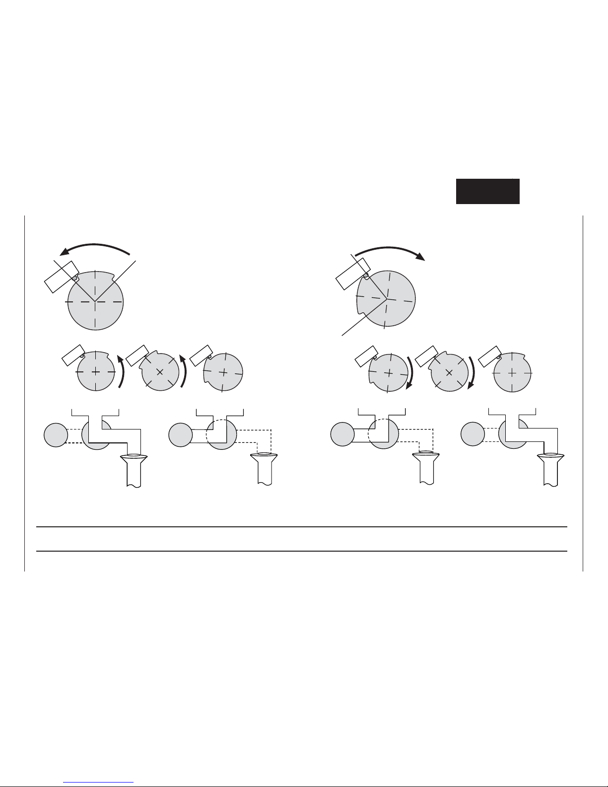
-78-
S
S
C
C
M6
M6
M6
M6
S12
S12
123 456
Control Drain Valve 54.00.357
Notes:
Page 79

-79-
S
S
C
C
Notes:
Page 80
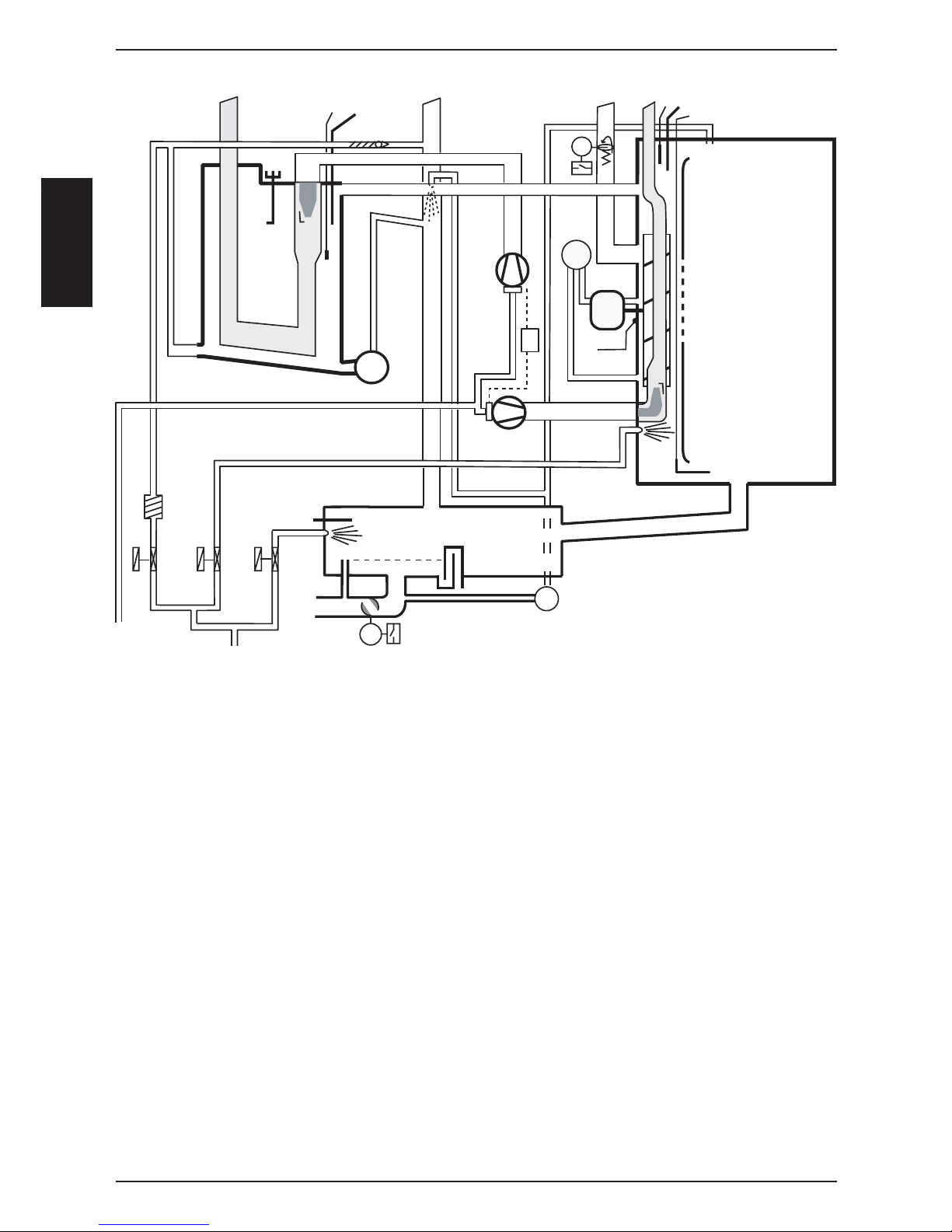
-80-
S
S
C
C
S2
B5
B1
B6
F4
P1
M3
S4
M4
M6
S11
Y1
Y3
Y2
B2
M1
B4
F3
M7
S12
M8
M9
A5
Y12
Y11
B12
B11
A5 Ignition module
B1 Thermocouple interior cabinet
B2 Thermocouple quenching
B4 Thermocouple humidity
B5 Thermocouple steam generator
B6 Thermocouple core temperature
B11 Ignition/monitoring electrode steam
B12 Ignition/monitoring electrode hot air
F3 Safety thermostat steam generator 135°C
F4 Safety thermostat interior cabinet 360°C
Y1 Solenoid valve fi lling
Y2 Solenoid valve quenching
Y3 Solenoid valve moistening
Y11 Gas valve steam
Y12 Gas valve hot air
M1 Fan motor
M3 Humidity motor
M4 SC-pump
M6 CleanJet pump
M7 Drain valve
M8 Gas blower motor hot air
M9 Gas blower motor steam
SCC Gas from 04-2004
S2 Level electrode
S4 Micro switch humidity motor
S11 CDS sensor
S12 Micro switch drain valve
P1 Pressure sensor humidity
Only fl oor untis 201 - 202
A6 Ignition module hot air bottom
(with jumper)
M2 Fan motor top (with jumper)
M10 Gas blower motor hot air bottom
Y13 Gas valve hot air bottom
B13 Ignition/monitoring electrode
hot air bottom
Page 81

-81-
S
S
C
C
Notes:
Page 82
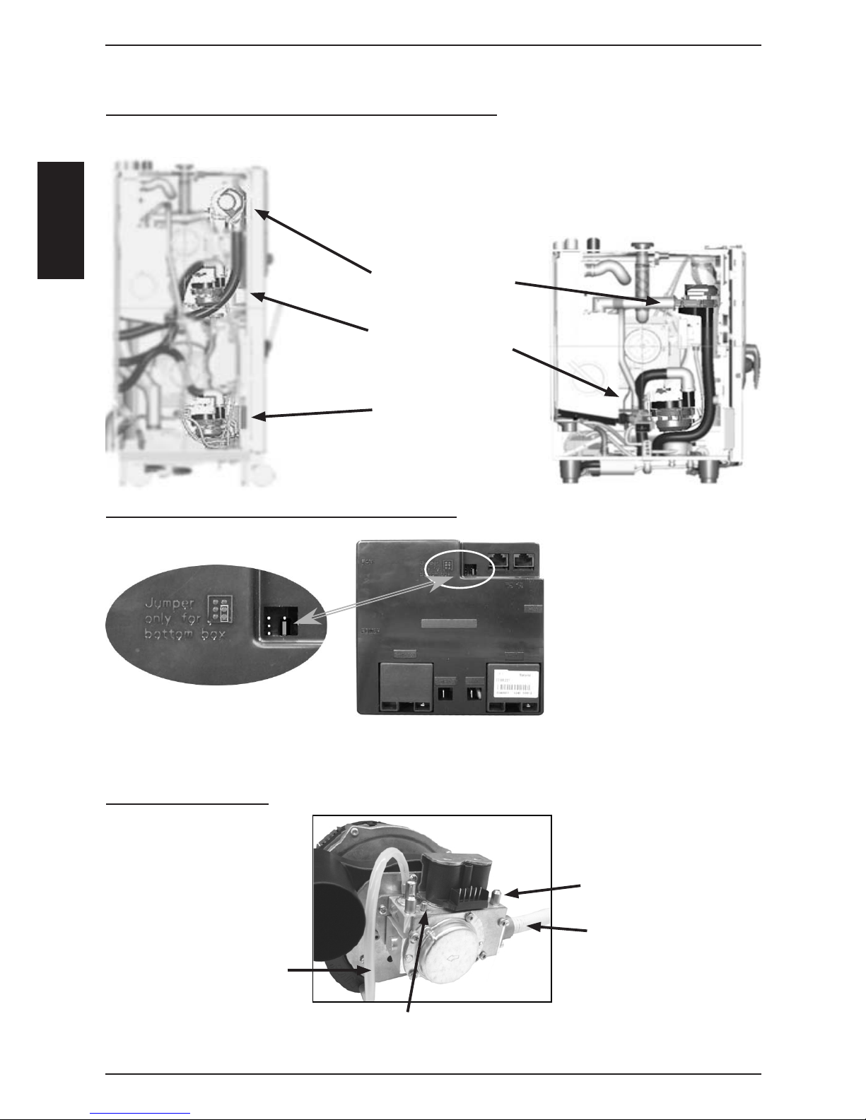
-82-
S
S
C
C
Identifi cation of the different gas burners / Gas blowers:
SCC 201 - 202
SCC 61 - 62 - 101 - 102
Steam Blower
(ignition box fi tted)
Hot Air blower top
(ignition box not fi tted)
Hot Air blower bottom
(ignition box fi tted)
Ignition box of Hot Air Blower, Bottom (201 - 202):
Jumper must ONLY be set
on Ignition Box for
Hot Air Blower Bottom
(201 - 202)
Gas valve components
Measuring test point for
gas fl ow pressure
Gas supply
Compensation hose
CO2 Srew
Basic info about SCC Gas from 04-2004
Ignition box
Page 83
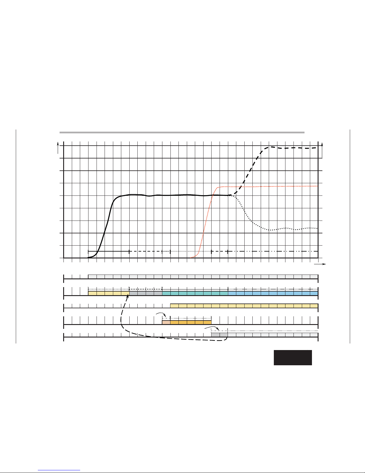
-83-
S
S
C
C
Sequence of events of Steam / Hot Air Burner (SCC as well as CM)
If no flame detected => new ignition sequence. After 5th ignition without success => RESET
16 2419 2017 1810 11 14 15
Speed of burner blower motor in U/min
21 22 23 26 27678901 45
8
4
3
2
1
2512 13
F l a m e c u r r e n t in µA
Time 2 3
7
6
5
Flame monitoring
Energise Solenoids: Black coils ca 205V DC / orange coils ca 108V DC
Ignition box gets heat demand over the BUS cable
Ignition, ca 20KV
Burner blower motor
Gas valve
Heat demand
Start - pre purge
about. 4-5 sec
Pre purge, 4 sec
RPM monitored
Blower runs with Start RPM
RPM monitoring by ignition box
Blower runs with Max or Min RPM
RPM monitoring by ignition box
Flame monitoring within. 2 sec
C
continuous flame control
Start RPM
Max RPM
Min RPM
sec
RPM
Igniti
on,5 secPre ignition, 1sec
Start up Pre purge
Pre ignition
Ignition Burner running
Flame
control
µA
Flame current
Page 84
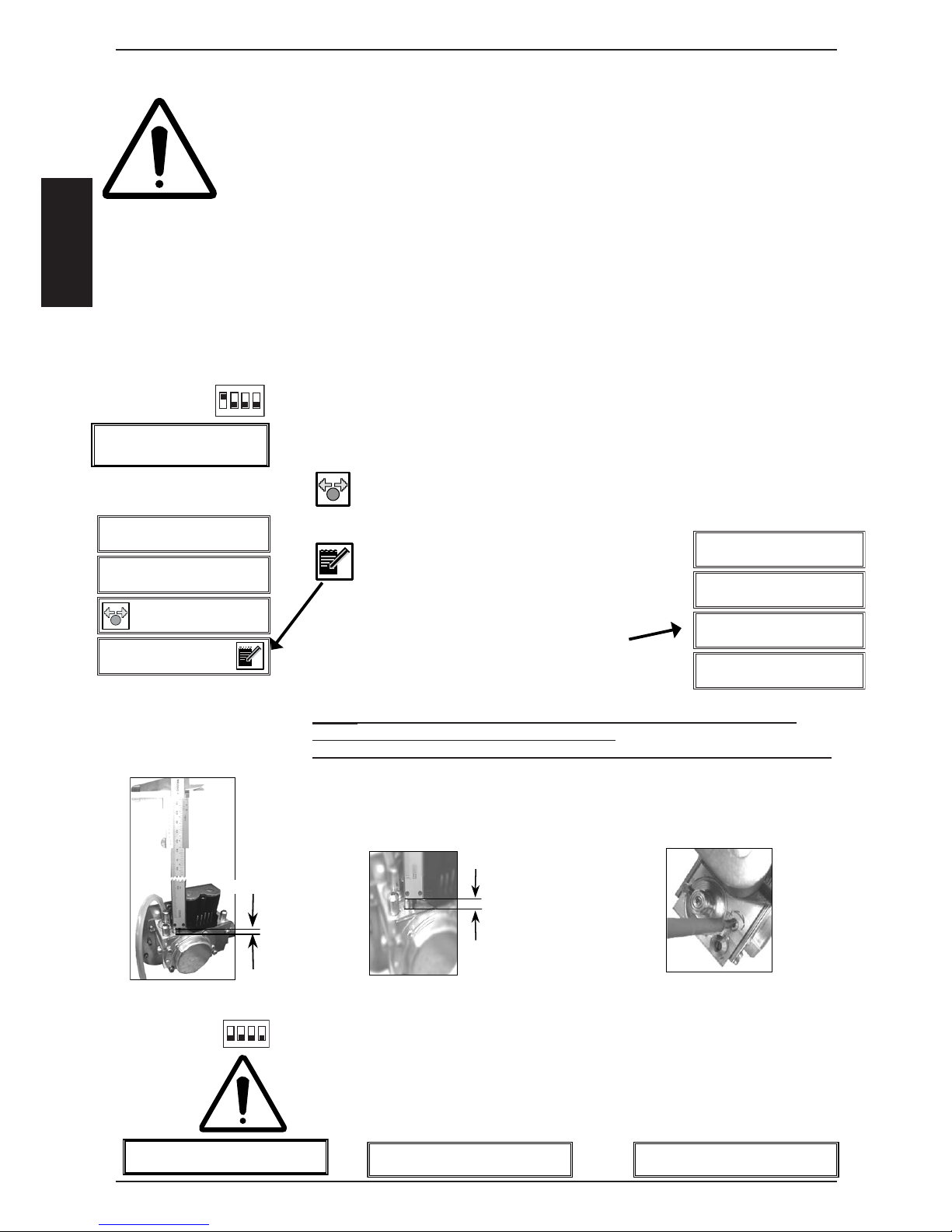
-84-
S
S
C
C
Check Gas Type - Gas conversion : SCC Gas from 04 - 2004
Whenever working on any gas component like:
Gas valve, gas blower and / or changing connected type of gas, a detailed fl ue gas analysis
MUST be done using adequate CO and CO2 measuring equipment!
This shall ONLY be done by trained technicians!
Always check appliance for possible gas leakages!
Danger:
Changing the gas type of your SelfCooking Center or Combi Master shall
only be done if you have a fl ue gas analyser at hand.
Changing the gas setting only by adjusting the CO2 screw will result in an
unsafe fl ue gas condition and is dangerous to life
and will damage the equipment.
Select Basic Settings:
A) • Switch on unit
• Open control panel
• Set DIP switch 1 on PCB to „ON“ position
• Select „Basic Settings
B) At „Basic Settings“ select position „Gas type“
C) Press key and select with the central dial the new gas type
G20=Natural Gas H, G25=Natural Gas L, G30=3BP, G31=3P,
13A=Natural Gas Japan
D) Confi rm new gas setting by pressing
the „Store“ key.
E) Select 3-Basic settings for average CO2 length
setting.
Note: Setting this screw to the given length shall ONLY bring the unit into
working condition with the newly supplied gas.
This does NOT replace fl ue gas analysis or make the fl ue gas analysis obsolete!
F) Set the CO2 screw according the values of the display or according the table
„Values for burner adjustments“(! ! ! Set all CO2 screws ! ! !)
If the mm setting of CO2 screw is too high, turn CO2 screw fi rst 2 turns clockwise
and then to the requested length (Screw adjustment tolerance)
G) Switch unit OFF and ON again to store newly gas type setting!
H) To exit service program set DIP switch 1 to „OFF“ position
I) Perform a complete fl ue gas analysis at Max speed of each burner
at the „Function Test“ ,as well as a cross-check of CO2 at Min speed
of each burner at the „Function Test“
x,x mm
x,x mm
3 - Basic Setting
Nat.H(G20)
Steam Hot Air1 Hot Air 2
4,3mm 2,8mm 2,9mm
Set CO2 screw
Check CO2
Gas Steam Bower
Gas Hot Air Bower Top Gas Hot Air Bower bottom
1
2
3
4
2 - Basic Setting
Gas type
Nat.H(G20)
1
234
on
1
234
on
Gas type
Page 85
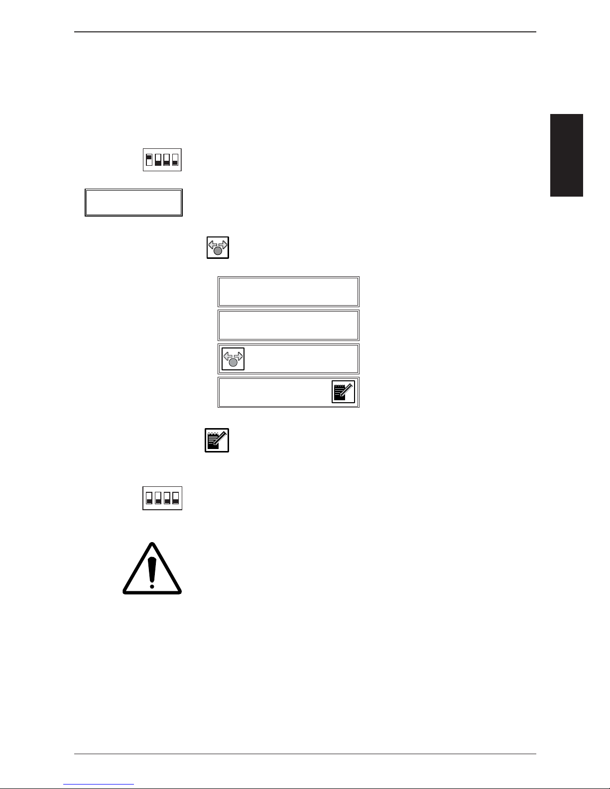
-85-
S
S
C
C
Adjustment of installation altitude above sea level
SCC Gas from 04 - 2004
Note: The altitude settings of 0-499 and 500-999m are identical.
Therefore resetting of installation altitude needs to be done only when installing
above 1000m (3280ft) or below sea level (i.e. Red Sea)
A) - Switch unit ON
- Open control panel
- Set DIP switch 1 on PCB to „ON“ position
B) At Basic Settings select position 4 - Installation altitude
C) Press Dial key and select desired altitude.
D) Confi rm new altitude setting with „Store“ key
E) Switch unit OFF and ON again to store new setting!
F) To exit service program set DIP switch 1 to „OFF“ position
Perform a complete fl ue gas analysis at Max speed of each burner
at the „Function Test“ ,as well as a cross-check of CO2 at Min speed
of each burner at the „Function Test“
1
2
3
4
4 - Basic Setting
Installation Altitude
1000 - 1499
Possible altitude selection:
-500 - -1m
0 - 499m
500 - 999m
1000 - 1499m
1500 - 1999m
2000 - 2499m
2500 - 2999m
3000 - 3499m
3500 - 3999m
4000 - 4499m
4500 - 4999m
1
234
on
1
234
on
Installation Altitude
above sea level
Page 86
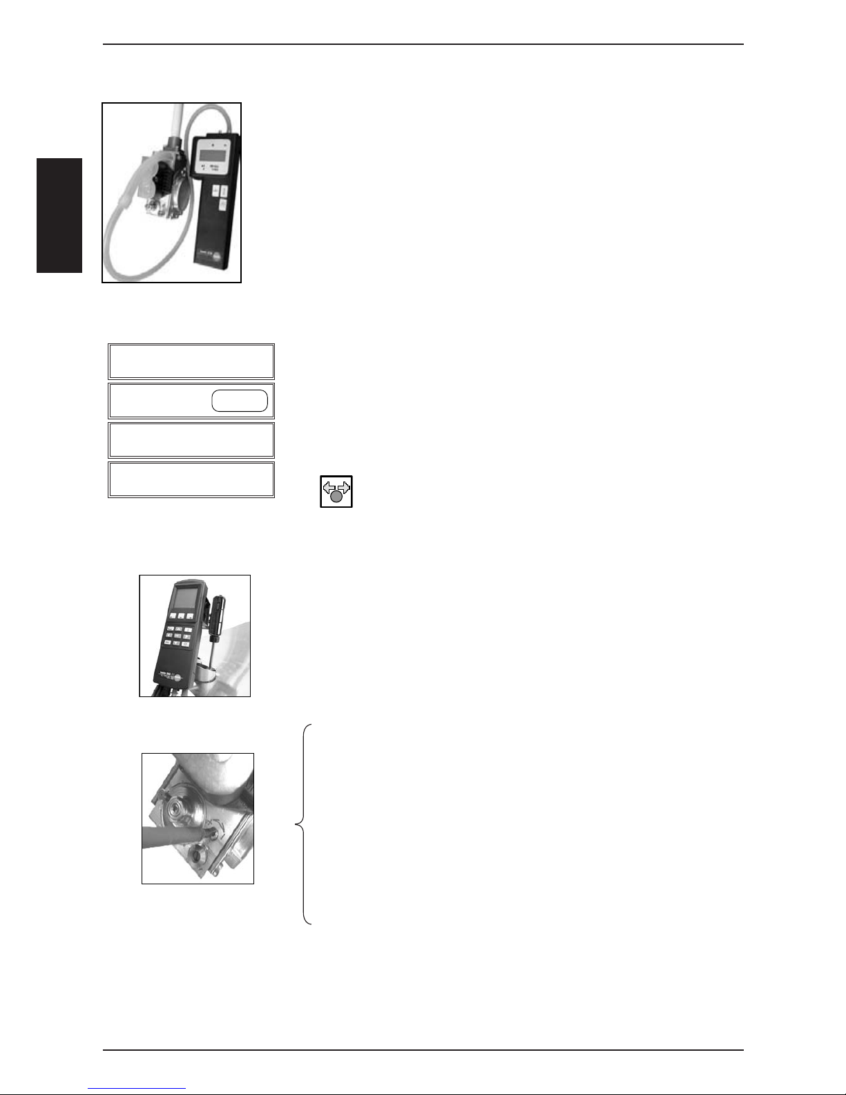
-86-
S
S
C
C
Before you carry out a fl ue gas analysis
check input gas fl ow pressure when burner is running
• Switch on unit. Select any mode and cooking time.
Wait till burner works
• Check input gas fl ow pressure
• See correct values of input fl ow pressure on serial plate
• If necessary adjust gas input pressure
Select „Function Test“:
• Switch on unit
• Open front panel
• Set DIP switch 1 on PCB to „ON“ position
• Select „Function Test“
Select at „FunctionTest“ the position „Gas Steam Burner“
Press key and select „Max“ rpm,
if it‘s not already selected
Activate the burner with the „Start“ key.
Note: Start key is used as a switch and will automatically
deactivate after 4 minutes
Display 4 indicates the desired CO2 value, e.g. 9,2%,
fl ame current, i.e. 5,2µA and the corresponding rpm of the
blower motor.
Place fl ue gas testing nozzle in correct fl ue outlet
„Adjust CO
2
to given value by turning CO2 screw on gas valve.
You also can fi nd that value on table „Values for burner adjustments“
• If CO
2
value is too low => turn CO2 screw
anti clockwise (+ direction),
• If CO2 value is too high => turn CO2 screw
fi rst 2 turns clockwise (- direction), and than slowly
anti clockwise (+ direction) until you get the indicated CO2
value. (Screw adjustment tolerance).
• CO value must be below 300ppm
Press „Stop“ key. Blower will stop.
Flue gas analysis: SCC gas from 04-2004
1
2
3
4
14 - Function Test
Gas Steam Blower Start/Stop
Max
CO2 FC xxx
See list 5,5 rpm
Flue gas analysis at MAX rpm - Cross-check of CO2 at MIN rpm
NOTE: Components are NOT protected against overload during function test!
A)
B)
C)
D)
E)
F)
G)
Page 87
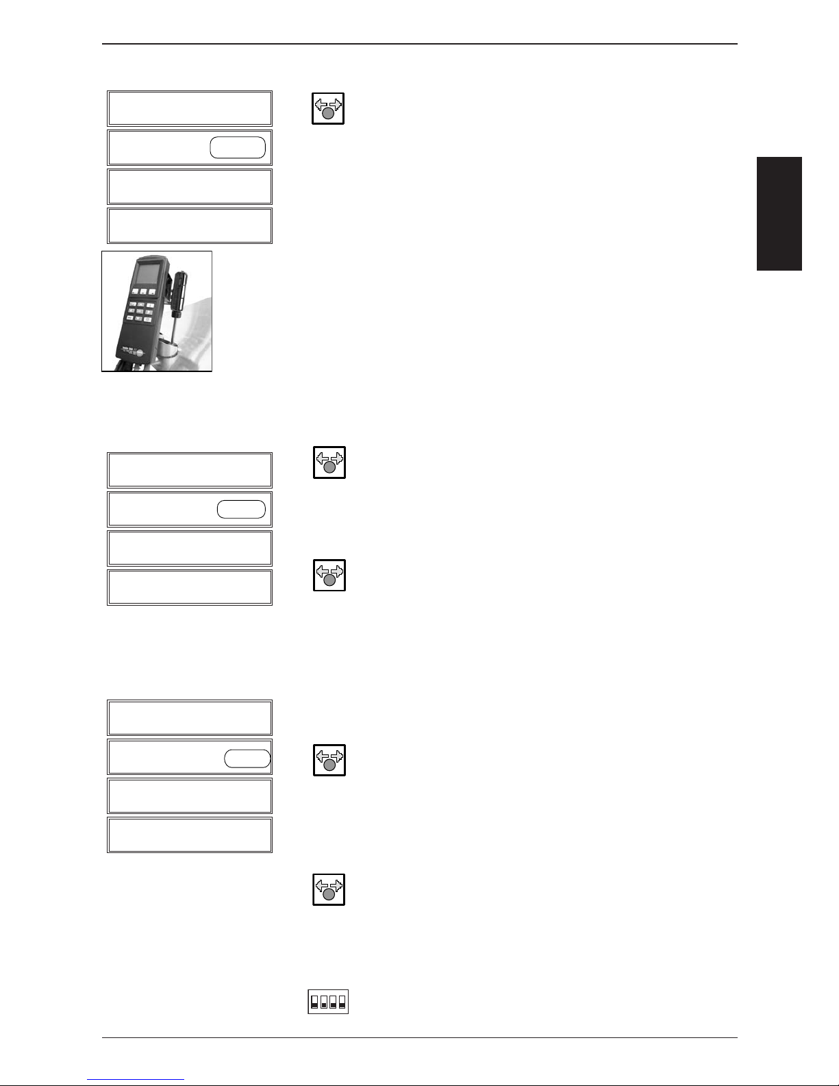
-87-
S
S
C
C
Flue gas analysis: SCC Gas ab 04 - 2004
1
2
3
4
14 - Function Test
Gas Steam Blower Start/Stop
Max
CO2 FC xxx
See list 5,5 rpm
H)
I)
J)
K)
L)
M)
N)
O)
P)
Q)
R)
S)
T)
U)
V)
Press key and select „Min“ speed.
Activate the burner with the „Start“ key.
Note: Start key is used as a switch and will automatically deactivate after 4 minutes
Display 4 indicates the desired CO
2
value, e.g. 9,2%,
fl ame current, i.e. 5,2µA and the corresponding rpm of the
blower motor.
For CO2 values also refer to table
„Values for burner adjustment“ in this manual.
Carry out a CO2 measurement to cross-check CO2 value only.
If CO2 value is out of allowed tolerance
=> Change gas valve
Press „Stop“ key. Blower will stop.
Select position 15 „Gas Hot Air Blower Top“
Press key and select „Max“ rpm,
if it‘s not already selected
Repeat steps D - G at „Max“ blower speed.
NOTE: Adjust CO2 to given value by turning CO2 screw on gas
valve !!
Press Key and select „MIN“ blower speed.
Repeat steps H-K at „MIN“ blower speed.
Carry out a CO2 measurement to cross-check CO2 value only.
If CO2 value is out of allowed tolerance
=> Change gas valve
SCC201 and SCC202 only:
Select position „Gas Hot Air Blower Bottom“
Press key and select „Max“ rpm,
if it‘s not already selected
Repeat steps D - G at „Max“ blower speed.
NOTE: Adjust CO2 to given value by turning CO2 screw on gas
valve !!
Press key and select „Min“ blower speed.
Repeat steps H - K at „Min“ blower speed.
Note: Cross-check CO2 value only. If CO2 value is out of
allowed tolerance => Change gas valve
To exit service program set DIP switch 1 to
„OFF“ position
1
2
3
4
15 - Function Test
Gas Hot Air Blower To p Start/Stop
Max
CO2 FC xxx
See list 5,5 rpm
1
2
3
4
16 - Function Test
Gas Hot Air Blower Bottom Start/Stop
Max
CO2 FC xxx
See list 5,5 rpm
1
234
on
Page 88
-88-
S
S
C
C
Input gas flow
pressure
Adjustment of
CO
2
- Screw
Input gas flow
pressure
Adjustment of
CO
2
- Screw
Input gas flow
pressure
Adjustment of
CO
2
- Screw
61
18 - 25 mbar
3,9 mm
18 - 25 mbar
3,8 mm
62
18 - 25 mbar 3,4 mm 18 - 25 mbar 3,5 mm
101
18 - 25 mbar 3,3 mm 18 - 25 mbar 3,3 mm
102
18 - 25 mbar 4,1 mm 18 - 25 mbar 3,5 mm
201
18 - 25 mbar 4,1 mm 18 - 25 mbar 3,4 mm 18 - 25 mbar 3,4 mm
202
18 - 25 mbar 4,1 mm 18 - 25 mbar 3,3 mm 18 - 25 mbar 3,3 mm
61
18 - 25 mbar
4,8 mm
18 - 25 mbar
6,0 mm
62
18 - 25 mbar 4,6 mm 18 - 25 mbar 4,7 mm
101
18 - 25 mbar 4,0 mm 18 - 25 mbar 4,3 mm
102
18 - 25 mbar 7,0 mm 18 - 25 mbar 4,5 mm
201
18 - 25 mbar 6,5 mm 18 - 25 mbar 4,2 mm 18 - 25 mbar 4,4 mm
202
18 - 25 mbar 6,5 mm 18 - 25 mbar 4,4 mm 18 - 25 mbar 4,5 mm
3B/P
100%
Butane
3B/P
100%
Butane
3B/P
100%
Butane
3B/P
100%
Butane
3B/P
100%
Butane
3B/P
100%
Butane
61
30 - 57 mbar
2,6 mm
10,4% 11,6% 9.3% 10,6% 30 - 57 mbar
2,5 mm
10,4% 11,6% 9,4% 10,4%
62
30 - 57 mbar 2,4
mm 10,4% 11,6% 8.5% 9,2% 30 - 57 mbar 2,4 mm 10,4% 11,6% 8,1% 9,6%
101
30 - 57 mbar 2,5 mm 10,4% 11,6% 8.4% 9,2% 30 - 57 mbar 2,3 mm 10,4% 11,6% 8,2% 9,6%
102
30 - 57 mbar 2,5 mm 10,4% 11,6% 8.9% 10,1% 30 - 57 mbar 2,4 mm 10,4% 11,6% 9,4% 10,3%
201
30 - 57 mbar
3,1 mm 10,4% 11,6% 8.8% 9,8% 30 - 57 mbar 2,8 mm 10,4% 11,6% 8,8% 9,6%
30 - 57 mbar
2,8 mm 10,4% 11,6% 8,8% 9,6%
202
30 - 57 mbar 2,5 mm 10,4% 11,6% 9.7% 11,0% 30 - 57 mbar 2,3 mm 10,4% 11,6% 9.7% 10,1%
30 - 57 mbar
2,3
mm 10,4% 11,6% 9.7% 10,1%
61
30 - 57 mbar
2,9 mm
30 - 57 mbar
2,5 mm
62
30 - 57 mbar 2,7 mm 30 - 57 mbar 2,5 mm
101
30 - 57 mbar 2,4 mm 30 - 57 mbar 2,7 mm
102
30 - 57 mbar 2,8 mm 30 - 57 mbar 2,6 mm
201
30 - 57 mbar
2,6 mm 30 - 57 mbar 2,4 mm
30 - 57
mbar
2,4 mm
202
30 - 57 mbar 2,3 mm 30 - 57 mbar 2,3 mm
30 - 57 mbar
2,3 mm
61
18 - 25 mbar 4,2 mm 18 - 25 mbar 3,5 mm
62
18 - 25 mbar 3,7 mm 18 - 25 mbar 3,4 mm
101
18 - 25 mbar 3,3 mm 18 - 25 mbar 3,1 mm
102
18 - 25 mbar 3,9 mm 18 - 25
mbar 3,4 mm
201 18 - 25 mbar 3,4 mm
18 - 25 mbar
3,1 mm 18 - 25 mbar 3,3 mm
202
18 - 25 mbar 3,2 mm 18 - 25 mbar 3,1 mm
18 - 25 mbar
3,5 mm
CO2
at "Min" rpm
- 0,2% / + 0,5%
9,0%
10,1%
9,5%
7,8%
8,7%
9,5%
8,2%
8,8%
9,3%
9,3%
11,1%
11,1%
7,8%
8,6%
CO
2
at "MAX" rpm
± 0,2%
CO2
at "Min" rpm
- 0,2% / + 0,5%
9,4%
9,4%
CO
2
at "MAX" rpm
± 0,2%
7,8%
8,7%
8,3%
8,0%
7,7%
9,5%
9,5%
8,4%
8,0%
8,2%
8,5%
8,2%
8,8%
9,5%
9,5%
9,5%
9,5%
11,1%
11,1%
9,1%
10,0%
11,1%
11,1%
11,1%
11,1%
9,8%
9,2%
9,7%
9,9%
9,3%
8,0%
7,7%
7,8%
8,3%
7,8%
8,6%
9,3%
9,3%
9,3%
8,6%
9,1%
9,4%
9,4%
9,4%
9,4%
9,4%
9,4%
9,3%
9,3%
7,8%
8,0%
8,5%
8,4%
9,7%
9,6%
10,7%
8,6%
CO2
at "Min" rpm
- 0,2% / + 0,5%
9,4%
8,9%
9,3%
7,8%
8,0%
9,0%
8,9%
9,5%
CO
2
at "MAX" rpm
± 0,2%
8,0%
7,9%
7,7%
8,4%
8,2%
8,8%
8,2%
7,8%
9,5%
9,5%
9,5%
9,5%
11,1%
11,1%
11,1%
9,5%
9,4%
11,1%
11,1%
11,1%
9,4%
9,5%
9,3%
9,3%
9,4%
9,3%
9,3%
9,3%
How to carry
out a burner
adjustment:
2.) Check the given length of the CO2 screw. See correct values from table above.
3.) Check gas input flow pressure. See correct values from table above.
Setting of exhaust values only by CO
2
screw adjustment. CO2 = see table above, CO = below 300ppm, if possible below 100ppm.
Carry out the CO
2
"Min" measurement. At CO2"Min" measurement no adjustment necessary on the CO2 screw => ! ! ! Check only the CO2 values ! ! ! !
Repeat same measurements at "Gas Hot Air Blower Top" and "Gas Hot Air Blower Bottom (201-202)".
1.
)
Check the gas type adjustment at "Basic Settings".
4.) Select "Gas Steam Blower" at "Function Test". Exhaust temperature should be during the "gas flow analysis" above 200°C.
Carr
y
out first a CO2"Max" adjustment.
Natural gas
Japan
(13A)
Natural Gas
Low
(G25)
LPG
3BP
(G30)
LPG
3P
(G31)
Values for burner adjustments of gas units SCC / CM (valid since March, 2006), entry in "red" => new
Type of gas
SCC - CM
Natural Gas
High
(G20)
Hot Air Burner - Bottom Side (only at 201-202)Steam Burner Hot Air Burner - Top Side
9,4%
9,4%
9,4%
Page 89
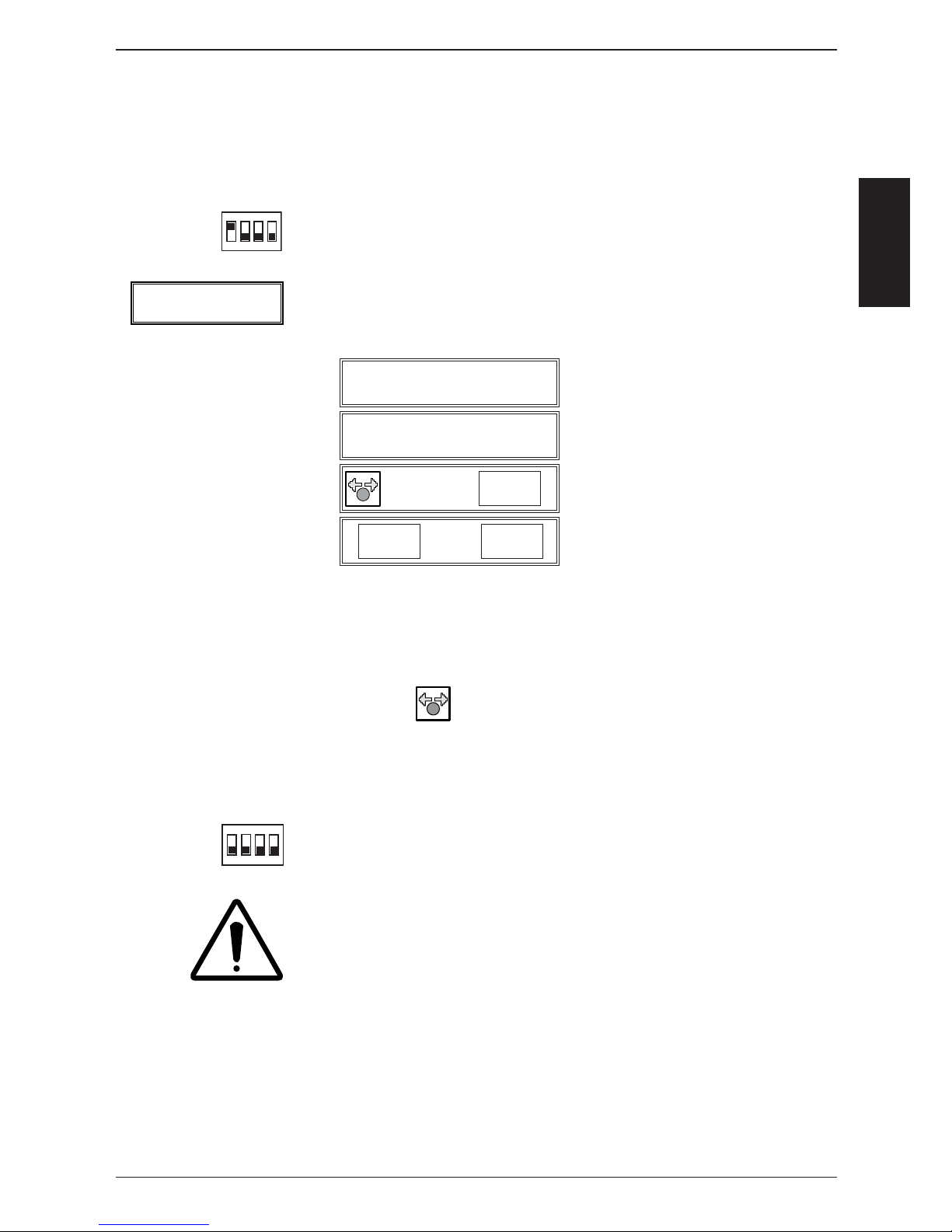
-89-
S
S
C
C
A) - Switch unit ON
- Open control panel
- Set DIP switch 1 on PCB to „ON“ position
B) At Basic Settings select i.e. position 5 - Gas Blower Steam
C) The factory stored blower speed is shown at MAX, Start und MIN.
D) To change the rpm of MAX, Start and MIN, select the desired step.
E) Set the new speed (given by the manufacturer) using the central dial.
F) To confi rm press the „Dial“ key again.
G) In order to change the other rpm settings of the same burner repeat steps
D-F accordingly.
H) Switch unit OFF and ON again to store newly gas type setting!
I) To exit service program set DIP switch 1 to „OFF“ position
Perform a complete fl ue gas analysis at Max speed of each burner
at the „Function Test“ ,as well as a cross-check of CO2 at Min speed
of each burner at the „Function Test“
Changing gas blower speed (MAX, Start, MIN rpm)
SCC Gas from 04 - 2004
1
2
3
4
5 - Basic Setting
Gas Blower Steam
Act. rpm Start rpm
xxxx xxxx
MIN rpm MAX rpm
xxxx xxxx
1
234
on
1
234
on
Gas Blower Steam
Page 90

S
-90-
COMMON
Flash SCC Software
The actual software version can be downloaded from:
www/rational-ag.de/service/technical_documentation/SCC-Line/Software
Software update by USB-stick
USB stick MUST be formatted in FAT (FAT16) format.
NOTE: Most standard USB Flash stick are not suitable for SCC Flash update!
RATIONAL confi gured USB Flash memory stick can be ordered under
part number: 87.00.010
Software can only be updated to the next higher version. Flashing software versions prior to
the existing version is NOT possible!
NOTE!
Software update on a unit with unknown software version (in case a pcb from spare
part stock is used) or in case the external EEPROM was faulty please observe the
procedure on the following page.
For Standard Software Update please proceed as follows:
1. Switch unit on
2. Wait until the operator mode of the SelfCooking Center is displayed.
3. Connect the USB stick with the actual software version to the USB interface of the
Rational SelfCooking Center.
4. Switch unit off and on again.
The unit will display „UPDATE“ followed by „Please don‘t touch“.
After the operator mode of the SelfCooking Center is displayed the USB stick can be
removed from the unit.
Notes: Please make sure your customer has always the latest software on his unit.
Please make sure you have the latest update.exe dated December, 6th, 2004
(12.06.2004) on your USB memory stick.
Page 91

-91-
S
S
C
C
Notes:
Page 92
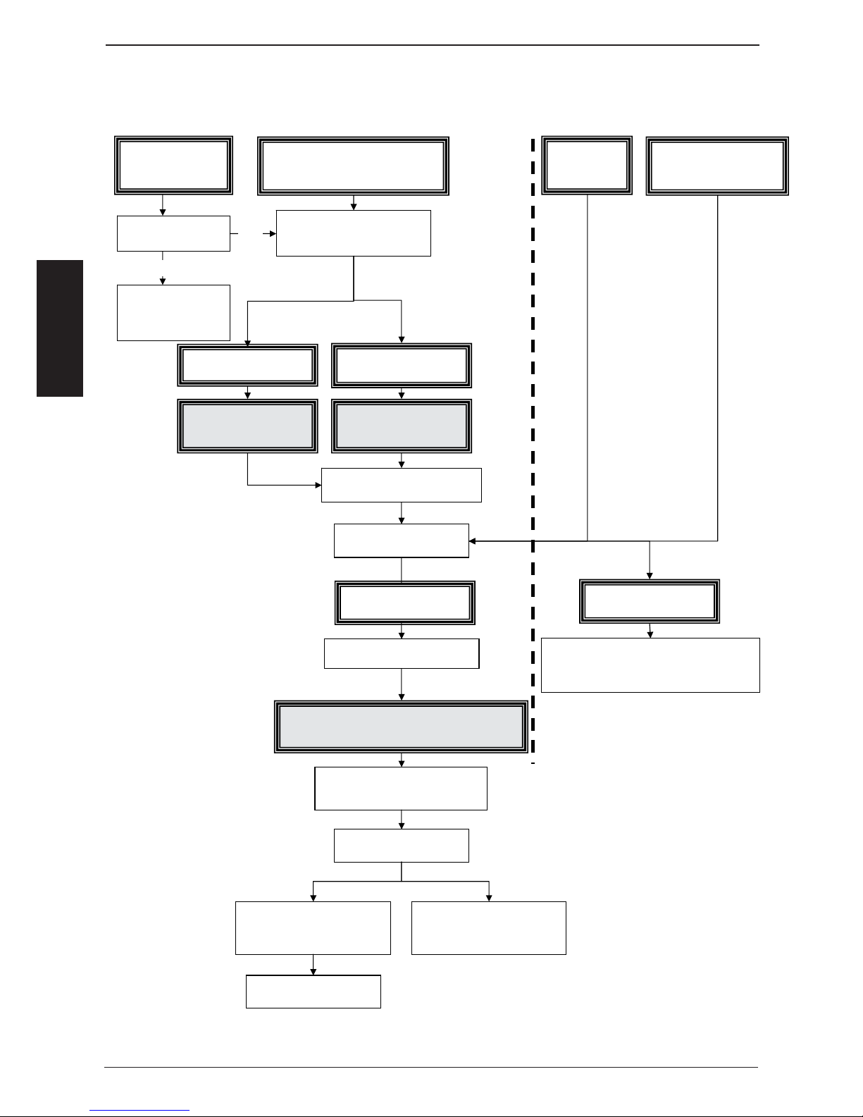
S
-92-
COMMON
Changing pcb
(pcb defectice)
EEPROM Data faulty (no display of
serial number, type) Service 17
Standard
Software
update
Green LED on main
pcb ON?
Isolate unit from power supply
(Disconnect control fuses)
check pcb transformer
primary and secondary
voltage (12VAC)
and plug connectors
changing pcb
EEPROM
data faulty
replace pcb, do NOT
connect EEPROM
disconnect old
EEPROM
Reconnect unit to power supply
(reconnect control fuses)
Software update
to 01-07-08 or higher
Isolate unit from power supply
(Disconnect control fuses)
connect original EEPROM after pcb
change or new replacement Eeprom
Reconnect unit to power supply
(reconnect control fuses)
switch unit ON
SCC display and type or serial
number OK
SCC display and in function / Type and new
software version OK, possible new data
strukture will be updated automatically.
standard Software update
Changing SCC pcb / changing SCC EEPROM / Software update
NO
Yes
changing pcb or EEPROM
data faulty
SCC display and type or serial
number NOT OK
contact Rational Service
Service 16
(from software 01-07-09)
Page 93

S
-93-
COMMON
Notes:
Page 94
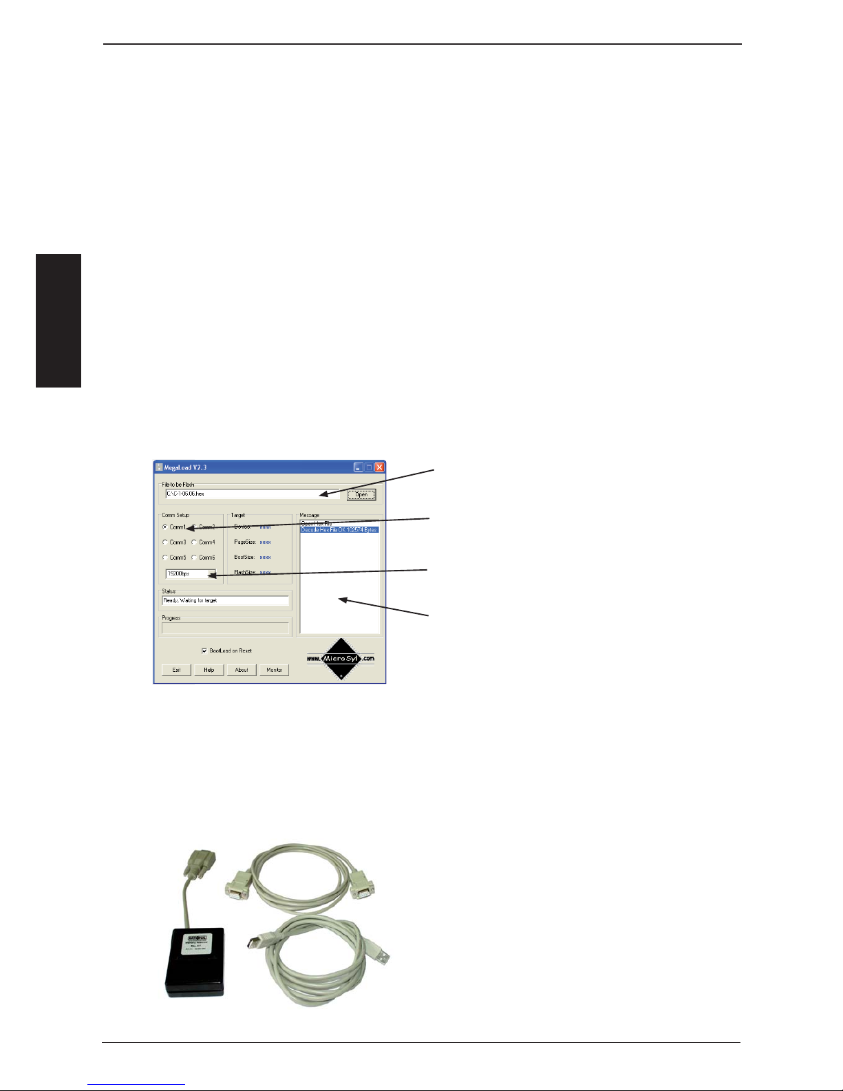
S
-94-
COMMON
Software update CM units with Flash-Box 87.00.037
For downloading unit software from PC to CM fl ash box the program „Megaload“ must
be installed on the PC.
This program is available on the Rational Service internet page under:
„Technical documentation/Software update SCC-Line/CM“.
For installation on the PC proceed as follows:
A) Download Zip fi le to PC
B) Open Zip fi le
C) Start the program Setup.exe and follow the description on the screen. After
the installation of the program Megaload the following procedure must be
observed
1. Download CM-Software e.g. C-1-06.05.hex of the above mentioned Rational
Service page into a folder (e. g. Desktop) of your computer.
2. Start the program Megaload
3. Carry out basic settings of the Megaload program.
Open CM Software;
e.g.: C-1-06.05.hex
Select desired interface on the PC,
e.g. Com1
Transfer rate must be set to 19200 bps.
On the „Message“ window the progress of
the download software download is indicated.
If your laptop is not equipped with a RS 232 interface (serial interface) an USB - RS232
adapter is required.
Operation and connection of the adapter can be found in the adapter‘s operator manual
The kit (87.00.037) contains of:
1. Flash box
2. Adapter cable RS 232
3. USB-cable
Hint
The Rs232adapter cable as well as the
USB cable are only required for down
loading the unit software to the Flash-Box.
Uploading unit software from Flash-Box to unit
only requires the Flash-Box (cables are not
needed).
Page 95
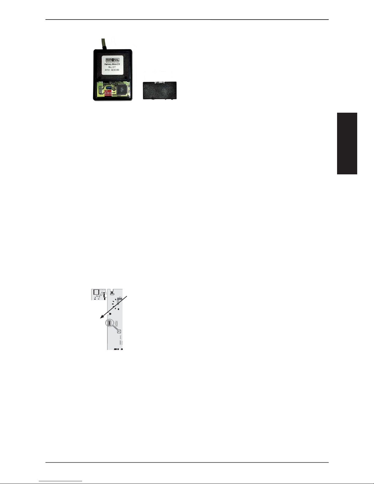
S
-95-
COMMON
Copying unit software from PC to CM Flash-Box
- Open lid of the Flash-Box
1. - Set DIP - switch 2 to „ON“.
(other switches remain in the off
position)
2. Connect RS 232 adapter cable (item 2) to Flash-Box and to the selected
interface (e. g. COM 1) of the PC
3. Start program Megaload and open fl ash software (e.g.: C-1-06.02.hex)
4. Connect USB-cable (item 3) to fl ash box and PC
5. After the USB cable was connected the fi les which are transferred will appear
on the Message window. An end sign indicates that the transfer is completed.
6. On the fl ash box set DIP- switch 2 to OFF and 3 to ON (the other switches
remain off). Flash-Box is ready for use
Update unit software with CM Flash-Box to unit
1. Switch off unit with mode switch and open front panel.
Check that DIP 3 is in the ON position.
2. Connect Flash-Box to RS 232 interface of the operator pcb.
3. Switch on CM unit. After the software update is completed the unit switches
off and back on again.
4. Now the Flash-Box can be removed and the unit can be used.
1
2
3
4
on
on
X7
X19
X20
X18
X23
X31
RS 485
X8
X12
X16
X17
X26
X27
X
3X32
X24
X24
X63
X63
F6.1
F6.1
F6
X3X4XX6
X2
X2
X50
X50
on
on
off
off
0,1 AT
0,1 AT
2 AT
X7
X7
X19
X19
X20
X20
F1F1F2
F2
0,1 AT
0,1 AT
2 AT
2 AT
Transformer
Transformer
X16
X16
42.00.004
42.00.047
X30
X30
RS 232
RS 232
Page 96
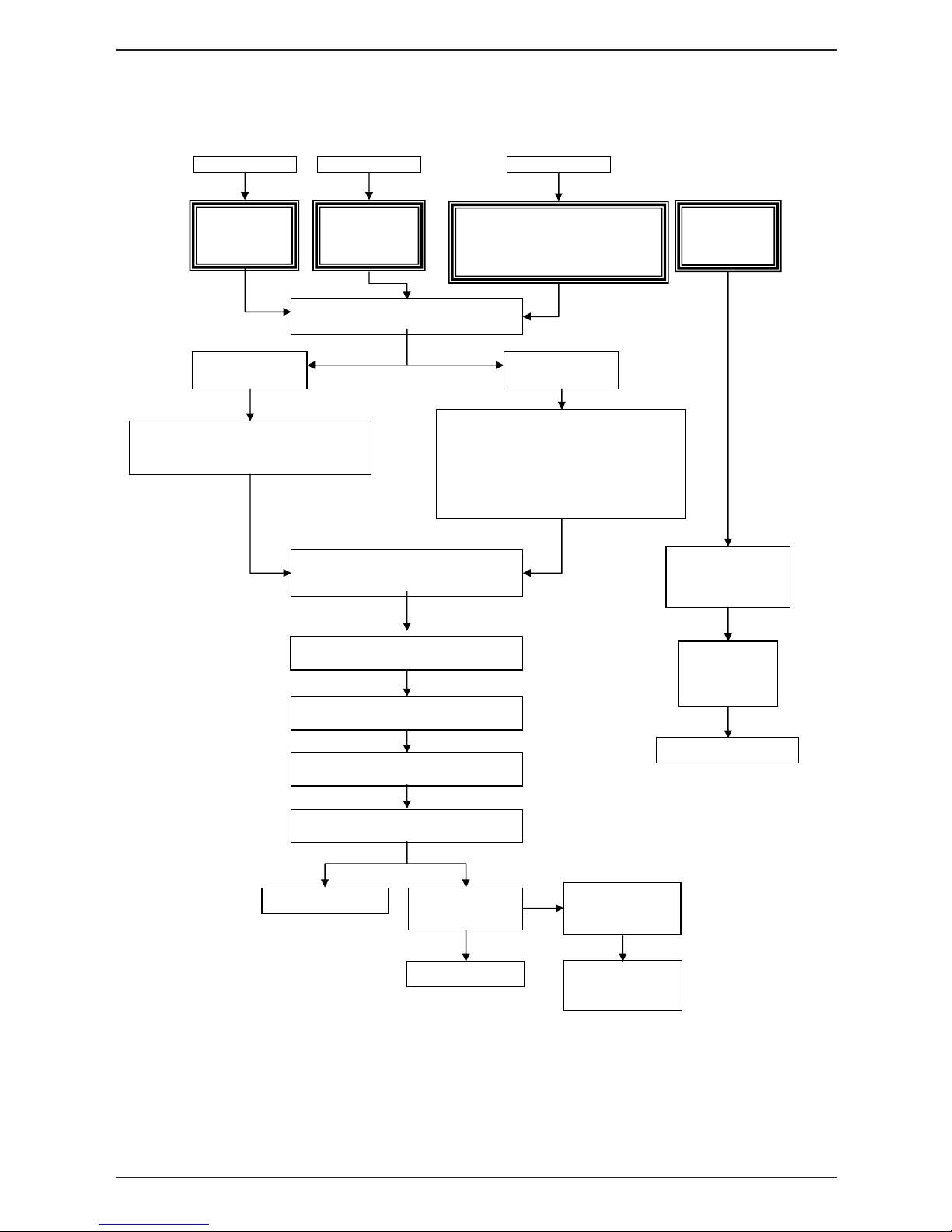
-96-
Fault tree: Changing pcb / changing EEPROM / Fault "E1"
Changing pcb
Software
update
Unit displays
"E1"
New EEPROM to be connected to
pcb with unknown SW version or
software version before C1-06-05
Isolate unit from power supply
(Disconnect control fuses)
Fault type: 1
Fault type:
2 or 3
Reconnect unit to power supply
(reconnect control fuses)
Replace pcb, do NOT connect
EEPROM as software version on new
pcb might not be known
NOTE:
Do NOT connect replacement EEPROM
to pcb as software version on pcb might
be too old!
New EEPROM might be
damaged again!
Update software to C1-06-05 or later
Reconnect unit to power supply
(reconnect control fuses)
OK
"E1" is still
displayed
Fault type 2 or 3
Contact Rational
Service
OK
Fault type: 1 Fault type: 2 Fault type: 3
Isolate unit from power supply
(Disconnect control fuses)
Reconnect EEPROM
Update software to
C1-06-05 or later
Software
update
OK
Page 97
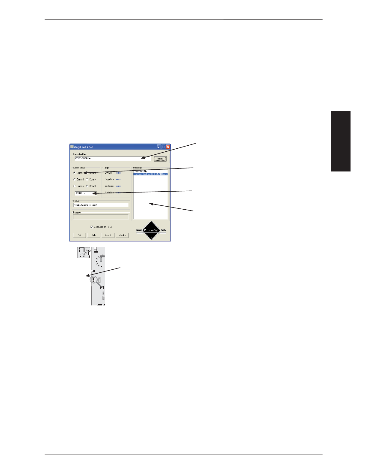
S
-97-
COMMON
How to update CM units via PC
To update a CM unit of new generation you have to use a software called
„Megaload“. To install the Software on your PC, you just have to excecute the
“Setup.exe” and follow the installation instructions on your screen. After Megaload installation please proceed as follows:
Save CM Software i.e. C-1-06.05. hex into a specifi c directory on your PC, (i.e.
desktop)
Run Megaload
Basic settings of Megaload:
Select software i.e. C1_06_05.hex
Select Com port, i.e. Com1
Transfer rate must be set to 19200 bps
After starting progress of software update
will be shown in the „Message“ window.
Connect RS232 interface of CM pcb and PC via
standard RS-232 cable.
If your laptop should not be equipped with a RS232 interface
(serial interface) then a USB - RS232 adapter is required.
For connection and operation of the adapter refer to the
user manual of the adapter
Switch CM unit on. After switching on you can see in the Message window,
how the fi les are transferred. Successful transmission will be indicated in this
window.
During fl ashing the CM display stays dark.
After successful software upload the unit will show the selected cooking mode,
temperature and time.
Close Megaloader via Exit button, disconnect RS 232 cable between unit and PC
CM is ready again.
1
2
3
4
on
on
X7
X19
X20
X18
X23
X31
RS 485
X8
X12
X16
X17
X26
X27
X
3X32
X24
X24
X63
X63
F6.1
F6.1
F6
X3X4XX6
X2
X2
X50
X50
on
on
off
off
0,1 AT
0,1 AT
2 AT
X7
X7
X19
X19
X20
X20
F1F1F2
F2
0,1 AT
0,1 AT
2 AT
2 AT
Transformer
Transformer
X16
X16
42.00.004
42.00.047
X30
X30
RS 232
RS 232
1.
2.
3.
4.
5.
6.
7.
8.
Page 98
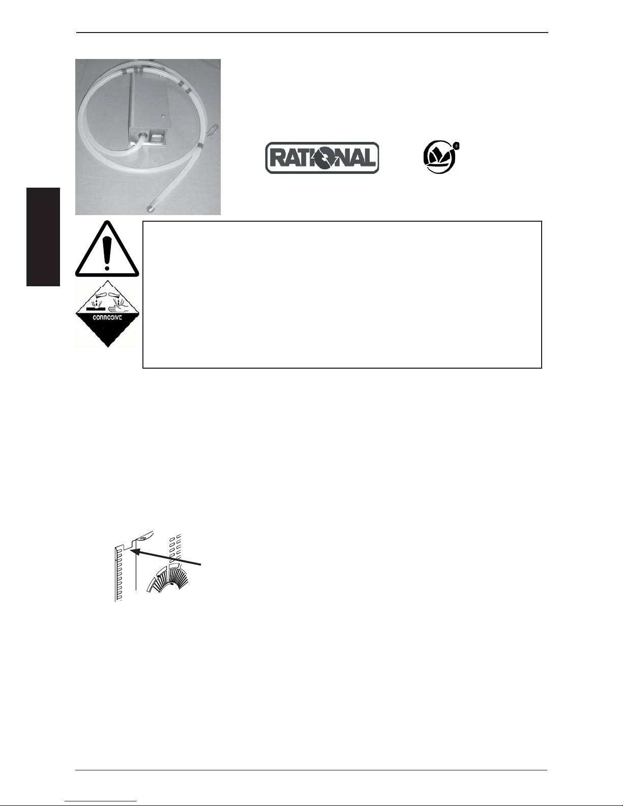
S
-98-
COMMON
The descaler pump 60.70.409 (230V) and 60.70.497 (110V)
must only be used to fi ll chemical part number: 6006.0110 into
steam generators of equipment bearing either of the following
marks on the data plate:
Warning!
When working with chemicals, i.e. aggressive cleaning materials, always wear protective clothing, goggles, face mask and gloves!
Caution:
Please observe all information given on the Material Safety Data Sheet
of your descaling chemical!
Only personnel specially trained on handling hazardous materials shall
follow the instructions below!
For further and detailed instructions please follow the descaling procedure given in the operator manual of the above mentioned units.
Unlatch the left side hinged rack and the air baffl e. Swivel them towards the right side.
Insert the pump hose marked with rings into the steam inlet port at the rear left top
corner of the interior cabinet.
The hose must be inserted at least to the following marking rings:
All electric heated units 3rd Ring 43cm (17“)
CM/SCC 61 and 62 Gas: 1st Ring 17cm (6,5“)
CM/SCC 101 and 102 Gas: 2nd Ring 31cm (12“)
CM/SCC 201 and 202 Gas: 3rd Ring 43cm (17“)
To prevent the hose from slipping out of the steam inlet port se
cure the hook which is attached to the hose at 100cm (40”) from
end of the hose onto the air baffl e cut out for the core probe as
indicated.
Insert the suction hose of the pump into the descaling liquid bottle. Please observe the
below listed quantities for descaler used for the different model sizes. Given Quantities
are average volumes and depending on Scale build up inside the steam generator.
Descaler volume for electric units (quantity in gal given as US gallons!)
SCC/CM 61 SCC/CM 62 SCC/CM 101 SCC/CM 102 SCC/CM 201 SCC/CM 202
3,6 L/0,95gal 6 L/ 1,6gal 6 L/1,6gal 8,5 L/2,25gal 9 L/2,4gal 11,6 L/3,06gal
Descaler volume for gas units SCC and CM
SCC/CM 61G SCC/CM 62G SCC/CM 101G SCC/CM 102G SCC/CM 201G SCC/CM 202G
4 L/1,1gal 6 L/1,6gal 7 L/1,85gal 9 L/2,4gal 8 L/2,1gal 11 L/2,9gal
1.
2.
3.
User instruction electrical descaler pump
Page 99

S
-99-
COMMON
Lean the cabinet door close and fi ll the above mentioned quantity of descaler at 10
sec intervals into the steam generator
NOTE: Descaling liquid can react very violently with the scale
inside the steam generator!
Should any foam appear at the steam inlet port stop fi lling and
wash the interior cabinet with fresh water.
After fi lling the required quantity remove the hose from the steam inlet port. Pump the
remaining liquid from inside the hose back into the descaler container bottle
Flush and rinse pump and pump hoses with fresh water.
Caution: not rinsing can cause internal corrosion of the pump.
Rinse the cabinet with fresh water.
Follow the further instructions given in the users manual for completing the descaling
User instruction electrical descaler pump
4.
5.
6.
7.
Descaling interrupt SCC:
As long as no descaler was fi lled into the steam generator the „Arrow back“ in window 1 is
still showing.
After the descaler was confi rmed to be fi lled the only way to interrupt the descaling process
is to:
- Switch unit OFF and ON again
- Press „Abort“
- Remaining time of 1:08 will be displayed
- If now the key „Aborted“ is pressed again and the unit is switched OFF and ON again
a remaining time of 23 min will show.
- After another 2 min this time display will drop to 5 min
- Now the steam generator will be fl ushed 2x. After this the „Arrow Back“ will be shown.
- By touching this key the descaling program will be exited
Note: Rinse the cabinet thoroughly with fresh water and operate the unit in steam mode
for some minutes.
- Now the unit can be accessed for cooking again.
Descaling interrupt CM:
- Switch unit OFF and ON again.
- Press core temperature key once.
- Remaining time of 20 min will be shown. During this time the steam generator will be
automatically fl ushed with fresh water and a steam cycle will follow.
Notes: Descaler foot pump is available under service part number 6004.0203
Page 100
S
-100-
COMMON
RATIONAL INSTALLATION / COMMISSIONING
CHECKLIST SCC / CM
To be completed individually for each Rational Combi installation.
This checklist has to be completed and returned within 14 days of installation / commission
to validate warranty.
Customer:
ADDRESS:
TELEFONE: _______________________________________
FAX: _______________________________________
SERIAL No _______________________________________
COMMISSIONED BY: (Authorized Service Agent ____________________________
Installation date: ____/____/____
Commissioning date: ____/____/____
Installation complies: does not comply: with install manual. (Please tick
)
Please fi ll the fi eld which are bold bordered with the information required.
If the measured values are NOT complying with the values in the installation manual please
inform the customer and your Rational dealer / offi ce.
We confi rm the installation was done according to the attached installation checklist, the
installation manual and all national and local codes which ever may apply.
The equipment was handed over free of defects. Operation, maintenance and cleaning of
the equipment was explained.
----------------------------------------- --------------------------------------SIGNATURE / DATE SERVICE AGENT SIGNATURE / DATE CUSTOMER
 Loading...