

Rational SCC201G Parts Manual
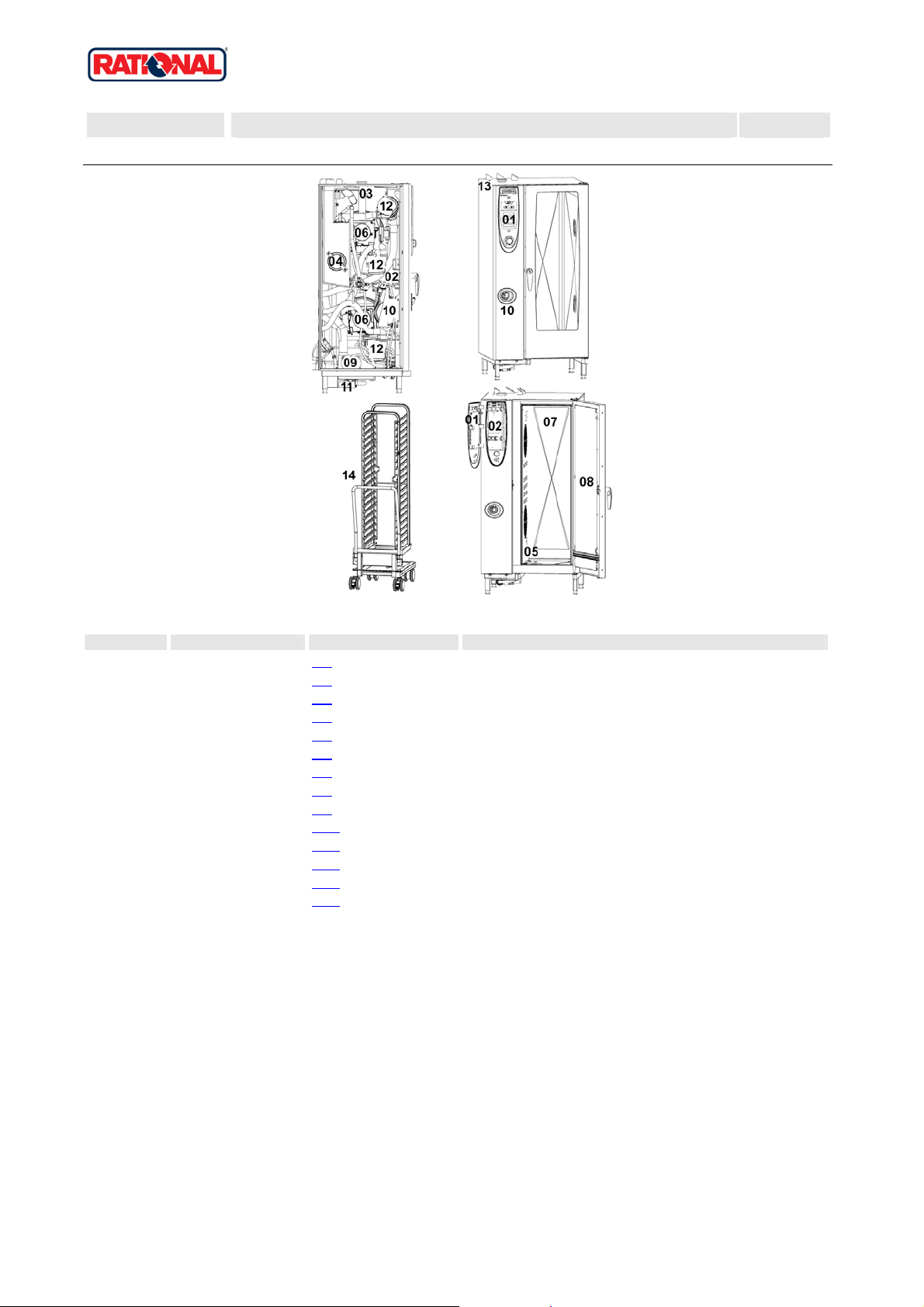
SCC 201G
Valid as of G21SE0404 up to G21SE....
Gas unit
X SCC 201G
Voltage 1 NAC 120V 60Hz
Item no. Part no Reference Description
1 X1 Control panel
2 X2
3 X3 Clima Plus
4 X4
5 X5 Hot air heating
6 X6
7 X7 Interior cabinet
8 X8
9 X9 Water supply, quenching box
10 X10
11 X11 CleanJet
12 X12
13 X13 Exterior cabinet
14 X14
Electrical installation
Steam generator, Bypass
Motor and fan wheel
Door
Hand shower
Gas parts
Miscellaneous
Version 2006 1

SCC 201G
Gas unit
X Table of contents
Voltage: 1 NAC 120V 60Hz
1 Control panel ..................................................................................................................3
1.A Control panel..........................................................................................................................................................4
2 Electrical installation .......................................................................................................5
2.A Contactor assembly ...............................................................................................................................................6
3 Clima Plus.......................................................................................................................8
3.A Hose set f. humidity control....................................................................................................................................9
4 Steam generator, Bypass .............................................................................................10
4.A Pump connection spout cpl..................................................................................................................................12
4.B Venting valve for steam generator .......................................................................................................................13
5 Hot air heating ..............................................................................................................14
5.A Burner hot air ....................................................................................................................................................... 15
6 Motor and fan wheel.....................................................................................................16
7 Interior cabinet..............................................................................................................17
7.A Interior cabinet .....................................................................................................................................................18
7.B Gasket frame w. glass a. gaskets ........................................................................................................................ 19
7.C Air baffle...............................................................................................................................................................20
7.C Air baffle...............................................................................................................................................................21
7.C Air baffle...............................................................................................................................................................22
8 Door..............................................................................................................................23
8.A Door .....................................................................................................................................................................25
8.C Door catch............................................................................................................................................................26
9 Water supply, quenching box........................................................................................27
10 Hand shower...............................................................................................................28
11 CleanJet......................................................................................................................29
12 Gas parts....................................................................................................................30
12.A Gas valve cpl. ND 055 RG148...........................................................................................................................32
12.B Gas valve cpl. WND 055 RG130........................................................................................................................33
13 Exterior cabinet...........................................................................................................34
13.A Exterior cabinet..................................................................................................................................................35
14 Miscellaneous.............................................................................................................36
2
SCC 201G
Valid as of G21SE0404 up to G21SE....
Gas unit
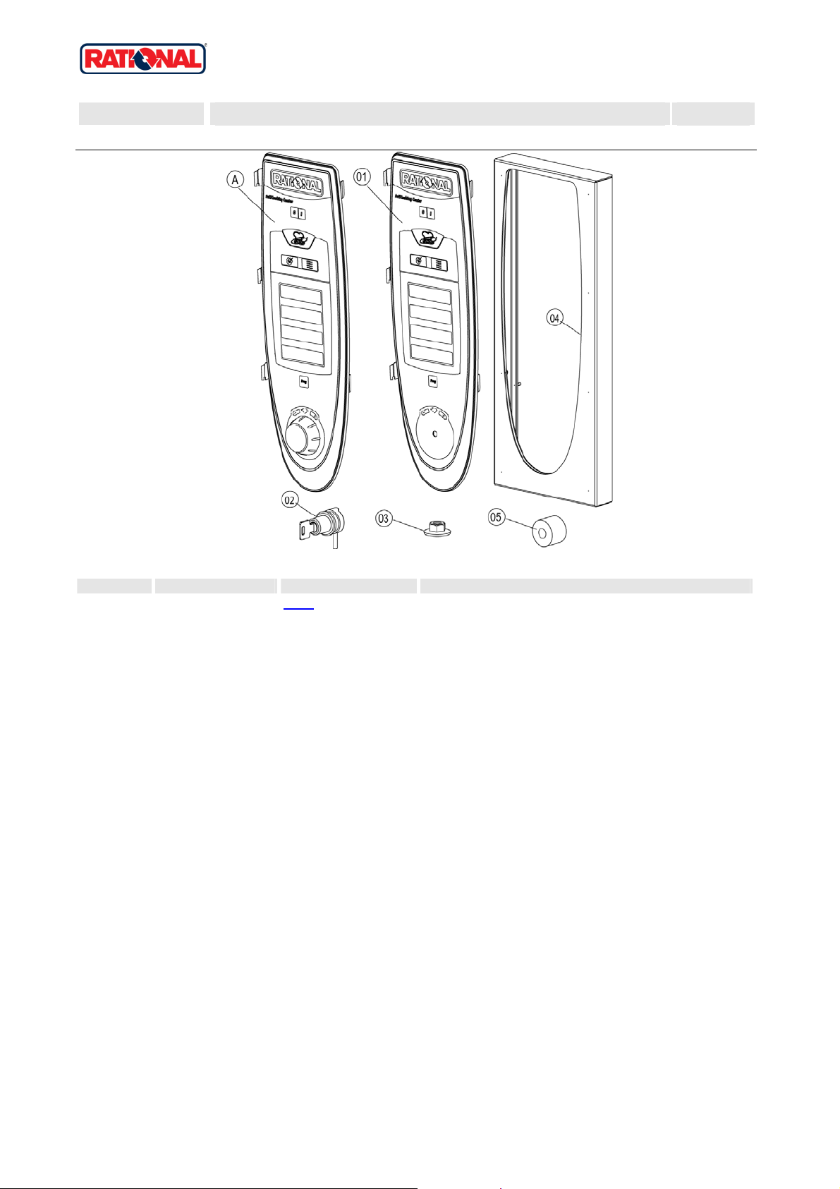
1 Control panel
1 Control panel
X 1 Control panel 1
Voltage 1 NAC 120V 60Hz
Item no. Part no Reference Description
A X1.A Control panel
1 87.00.002 Control panel insert with overla y
5 2039.0326 Spacer for pcb
Attention! Individual parts shown might not be used in this component group!
Version 2006 3
SCC 201G
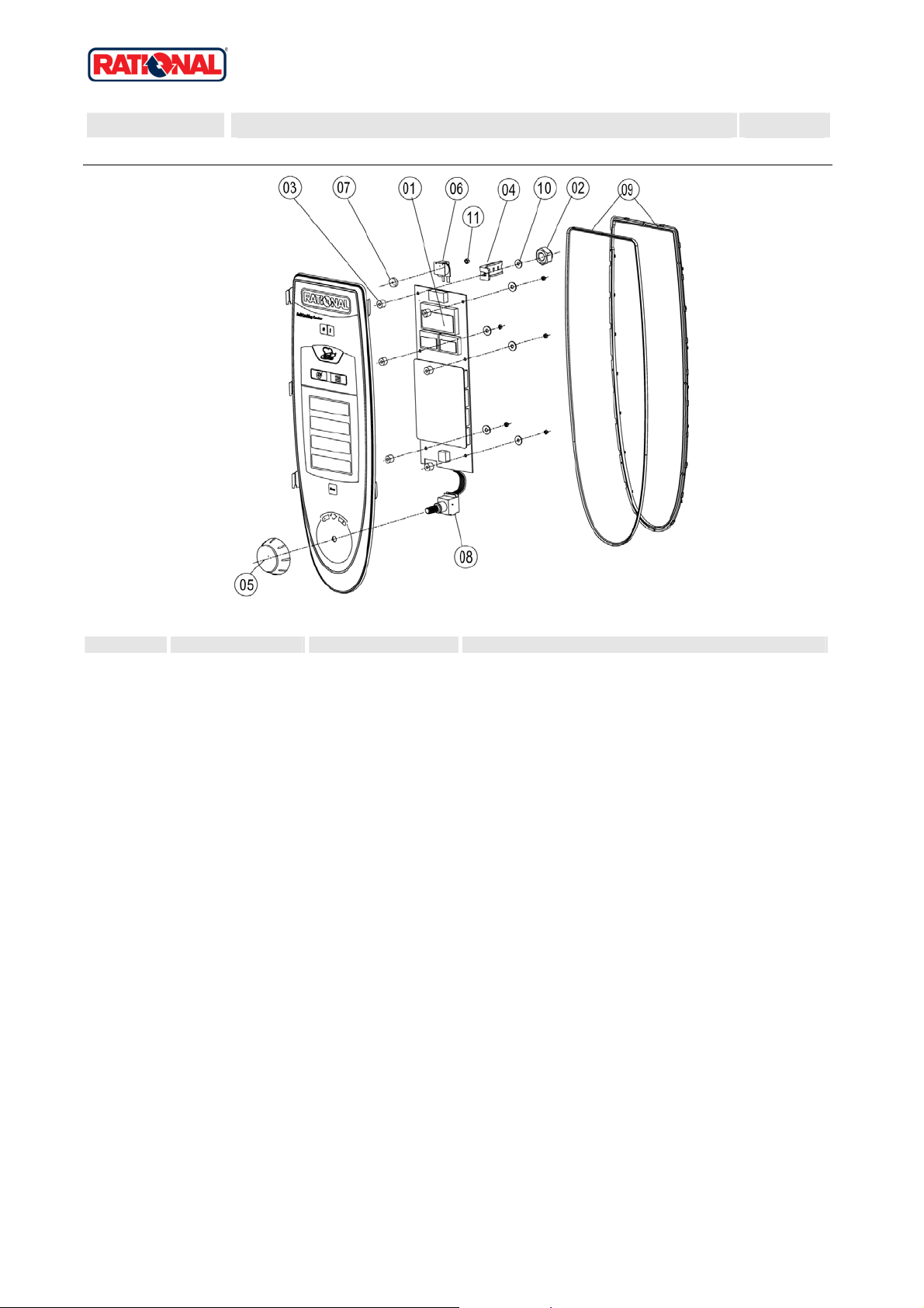
Valid as of G21SE0404 up to G21SE....
Gas unit
1 Control panel
1.A Control panel
X 1.A Control panel 1
Voltage 1 NAC 120V 60Hz
Item no. Part no Reference Description
1 42.00.002 Control pcb
2 1104.0121 Hex nut M4 self locking
3 10.00.355 Spacer black
4 2020.0400 F ixing device for cable harness
5 16.00.232 Dial f. pulse generator
6 40.02.087 Buzzer
6 3006.0107 Buzzer
7 5110.1029 Gasket mode switch
7 5110.1028 Gasket poti hot air, core temperature
8 40.00.404 Pulse generator
9 16.00.387 Mounting device f.sealing + sealin g lip
10 1306.0218 Washer A4,3
11 1103.0122 He x nut M3 self-locking
Attention! Individual parts shown might not be used in this component group!
Version 2006 4
SCC 201G
Valid as of G21SE0404 up to G21SE....
Gas unit
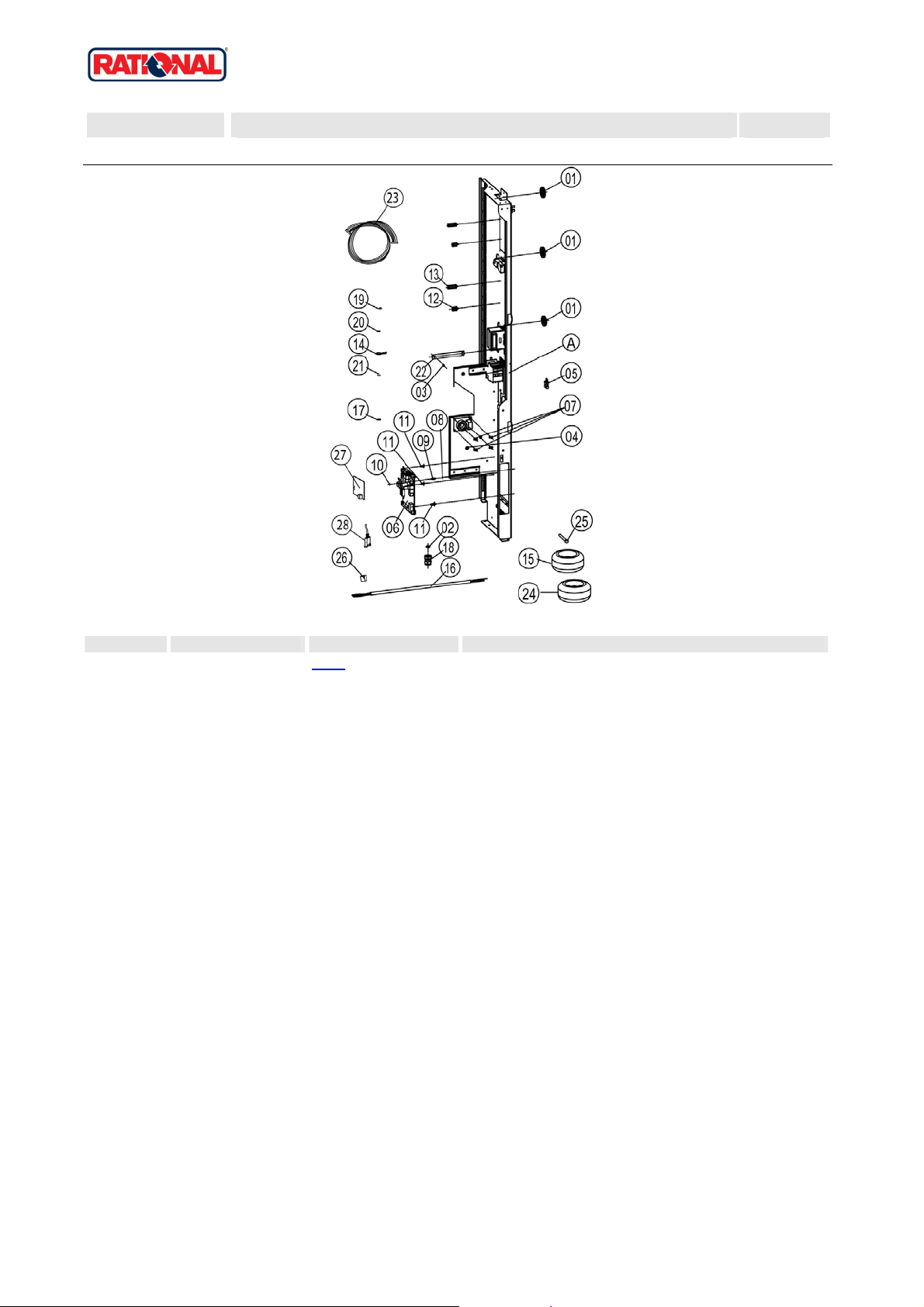
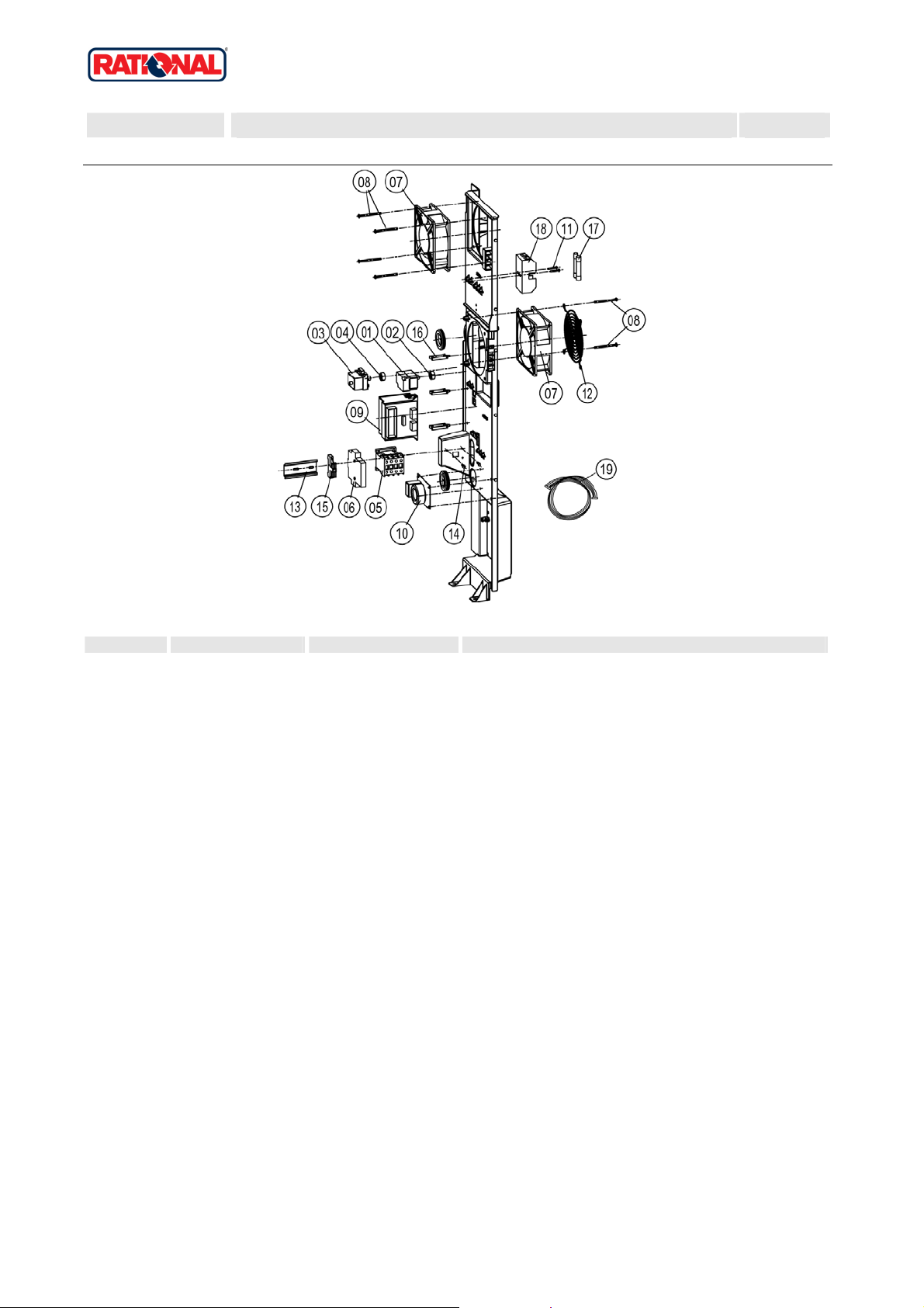
2 Electrical installation
2 Electrical installation
X 2 Electrical installation 2
Voltage 1 NAC 120V 60Hz
Item no. Part no Reference Description
A X2.A Contactor assembly
1 4007.0620 Membrane DGC 29
2 10.00.510 Grommet 10/12/16-2
3 1106.0224 Hex nut M6 self locking
5 42.00.007 External memory
6 40.00.049 Relay-I/O pcb
6 42.00.045 Relay-I/O pcb w/o Sicotronic
7 40.00.417 Fixing clip f. pcb
8 1104.0801 Cag e nut M4
9 10.00.243 Spacer M4x8
10 1104.0120 Hex nut M4
11 40.01.579 Fixing clip f. pcb
12 10.00.112 Cable clip short
13 10.00.111 Cable clip long
14 10.00.471 Cable clip d10-12mm
16 40.01.597 Power supply cable 3xAWG14
18 40.00.320 Cable connection M20x1.5
19 1106.0160 Hex nut M6
20 1206.0120 Tooth lock washer A6,4
21 4002.0110 Cable connector, junction
22 40.01.132 Center fixation f. contactor assembly
23 40.01.091 Bus cable 0.4m
23 40.00.471 Bus cable 0.8m
23 40.00.472 Bus cable 1.3m
24 40.00.281 Power transformer
25 10.00.445 Hex screw M8x80
26 40.01.600 Insulating screw joint 2pol.
Attention! Individual parts shown might not be used in this component group!
Version 2006 5
SCC 201G
Valid as of G21SE0404 up to G21SE....
Gas unit
2 Electrical installation
2.A Contactor assembly
X 2.A Contactor assembly 2
Voltage 1 NAC 120V 60Hz
Item no. Part no Reference Description
1 3014.0328 Dry up protector 275°F/135°C
2 3014.0302 He x nut M10 for dry-up protector
3 40.01.482 Safety temperature limiter 365°C
4 3014.0327 Hex nut M10x1,0
5 40.00.451 Contactor MC1A 310 AH6
7 40.00.474 Cooling fan D.C.
8 10.00.238 Screw Torx 4x50
9 40.00.277 Control transformer
10 40.01.483 Electronic noise filter
11 40.00.592 Transformer f. cooling fan
12 1105.0120 Hex nut M5
13 1305.0160 Washer A5,3x10mm
14 40.01.272 Plug positioning bar I/O pcb
15 4001.1203 End plate for mounting rail
16 2620.370233 Installati on rail for Contactor 100mm
16 2620.380129 Installati on rail for Contactor 130mm
16 2816.1307 Installati on rail for Contactor 140mm
17 10.00.061 Pan head screw Torx T20 M4x12
18 10.00.111 Cable clip long
19 40.01.588 Fuse SC-8A 10x38
20 40.01.487 Fuse holder 2pol
21 10.00.364 Pan head screw Torx M3x12
22 40.00.221 Cable burner blo wer
22 40.01.485 Cable burner blo wer
22 40.00.209 Cable buzzer
22 40.01.541 Cable CDS sensor
22 40.01.301 Cable control harness
22 40.00.225 Cable control transformer sec.
22 40.01.543 Cable control transformer sec.
22 40.00.238 Cable differencial pressure switch
Attention! Individual parts shown might not be used in this component group!
Version 2006 6

SCC 201G
Valid as of G21SE0404 up to G21SE....
Gas unit
2 Electrical installation
Item no. Part no Reference Description
22 40.00.230 Cable gas valve
22 40.00.249 Cable harness isolating transformer
22 40.00.208 Cable humidity control
22 40.01.542 Cable level electrode
22 40.00.226 Cable SC pump
22 40.00.203 Cable solenoid valve
22 40.00.237 Ground wire
X 2.A Contactor assembly 2
Voltage 1 NAC 120V 60Hz
Attention! Individual parts shown might not be used in this component group!
Version 2006 7
SCC 201G
Valid as of G21SE0404 up to G21SE....
Gas unit
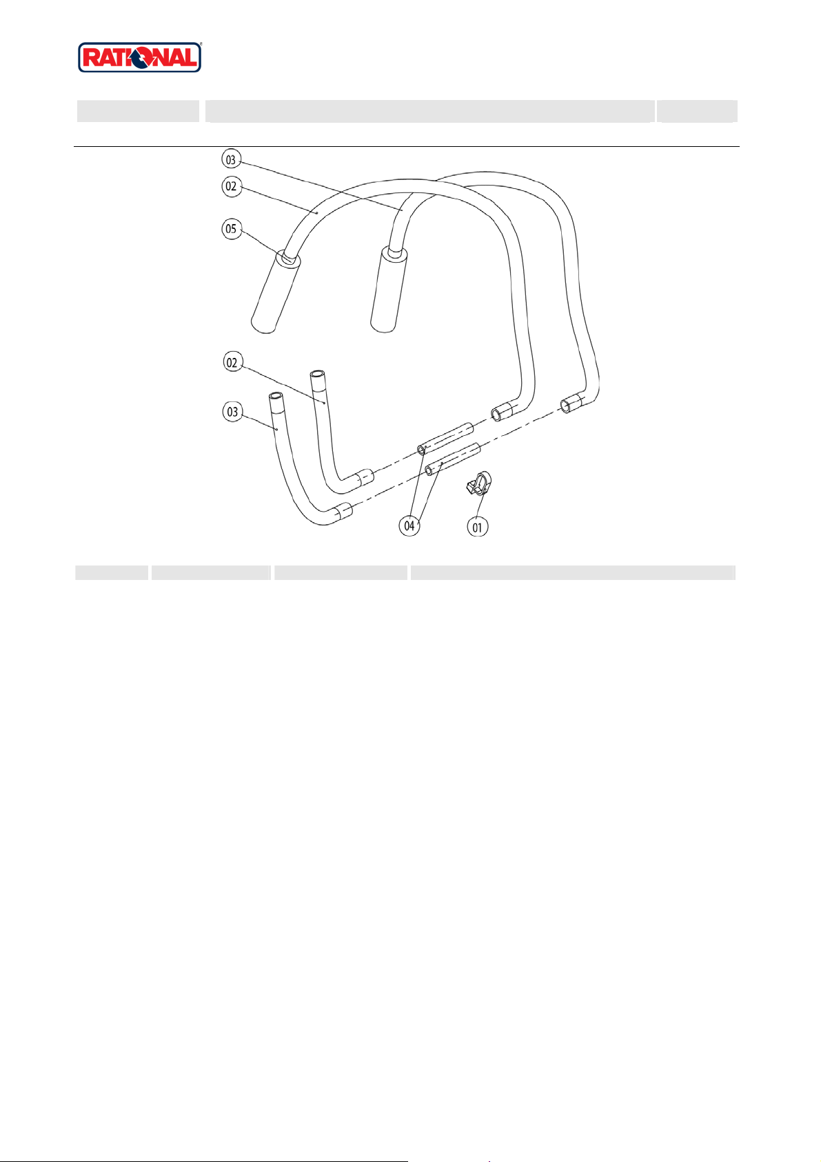
3 Clima Plus
3 Clima Plus
X 3 Clima Plus 3
Voltage 1 NAC 120V 60Hz
Item no. Part no Reference Description
A 22.00.256 X3.A Hose set f. humidity control
1 22.00.199 Inner humidity meas. Piece
2 22.00.318 Humidity control cpl. with motor
3 22.00.200 Outer humidity meas. Piece
4 22.00.198 Gasket f. hum. meas. Pipe
5 22.00.214 Hose d50x202
6 2066.0531 Hose clamp ø56
7 2001.0124 Compression spring
9 3017.1011 Pressure se nsor for humidity control Huba 401
11 3101.1010 Humid ity control motor
12 3016.0102 Micro switch
13 3101.1021 Protecting ca p f.12VDC humidity motor
Attention! Individual parts shown might not be used in this component group!
Version 2006 8
SCC 201G
Valid as of G21SE0404 up to G21SE....
Gas unit
3 Clima Plus
3.A Hose set f. humidity control
X 3.A Hose set f. humidity control 3
Voltage 1 NAC 120V 60Hz
Item no. Part no Reference Description
1 4005.0101 Tie rap 145 mm
2 2110.1020 Silico n hose ø5x1.5 blue
3 2110.1019 Silicone hose ø5x1,5 "red"
4 1900.0203 Ceramic tu be 8x5x60mm for
5 2112.1338 Silicone hose ø8x2x20
Attention! Individual parts shown might not be used in this component group!
Version 2006 9
SCC 201G
Valid as of G21SE0404 up to G21SE....
Gas unit
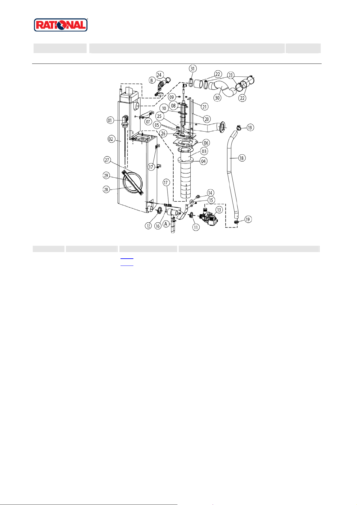
4 Steam generator, Bypass
4 Steam generator, Bypass
X 4 Steam generator, Bypass 4
Voltage 1 NAC 120V 60Hz
Item no. Part no Reference Description
A 8354.1320 X4.A Pump connection spout cpl.
B 8354.1304 X4.B Venting valve for steam generator
1 44.00.514 Filling level electrode 175mm
2 44.00.186 Steam generator insolated
3 72.00.010 Burner steam gen.
4 72.00.048 Insulation f. burner steam gen.
5 1104.0122 He x combination nut M4 galv
6 72.00.020 Gasket f. burner carrier
7 1105.0121 He x combination nut M5 galv
8 44.00.249 Ignition electrode steam generator
9 1104.0120 Hex nut M4
10 44.00.250 Gasket f. ignition electrode
11 2066.0519 Hose cl amp 35,6mm
12 2066.0526 Hose cl amp ø46mm
13 44.00.207 Emptying pump
14 1006.0762 Hex screw M6x10
15 1306.0222 W asher A6,4 x15x1,5
16 44.00.226 Fixing device f. pump steam generator
17 1106.0803 He x combination nut M6 galv
18 44.00.231 Drain hose steam generator
18 44.00.238 Drain hose steam generator
19 2066.0518 Hose clamp 30mm
20 40.00.291 Thermocouple steam generat or
20 40.00.292 Thermocouple steam generat or
21 44.00.518 Fixing plate steam generator thermostat
22 2112.1006 Steam hose 50x7mm
23 2066.0504 Hose clamp 40-60mm
24 2066.0506 Hose clamp 20-32mm
25 1105.0120 Hex nut M5
26 1205.0120 Tooth lock washer A5,3
Attention! Individual parts shown might not be used in this component group!
Version 2006 10

SCC 201G
Valid as of G21SE0404 up to G21SE....
Gas unit
4 Steam generator, Bypass
Item no. Part no Reference Description
27 5012.0566 Gasket que nching chamber 0-ring
28 44.00.263 Panel for revision hole steam generator
29 44.00.264 Clamping bar for panel revision hole
30 44.00.351 Steam pipe
31 2066.0300 Hose clamp 50-70 mm
X 4 Steam generator, Bypass 4
Voltage 1 NAC 120V 60Hz
Attention! Individual parts shown might not be used in this component group!
Version 2006 11
 Loading...