

Rational CombiMaster Plus series, CombiMaster series, SelfCookingCenter WE series, SelfCookingCenter XS series Installation Manual
Page 1
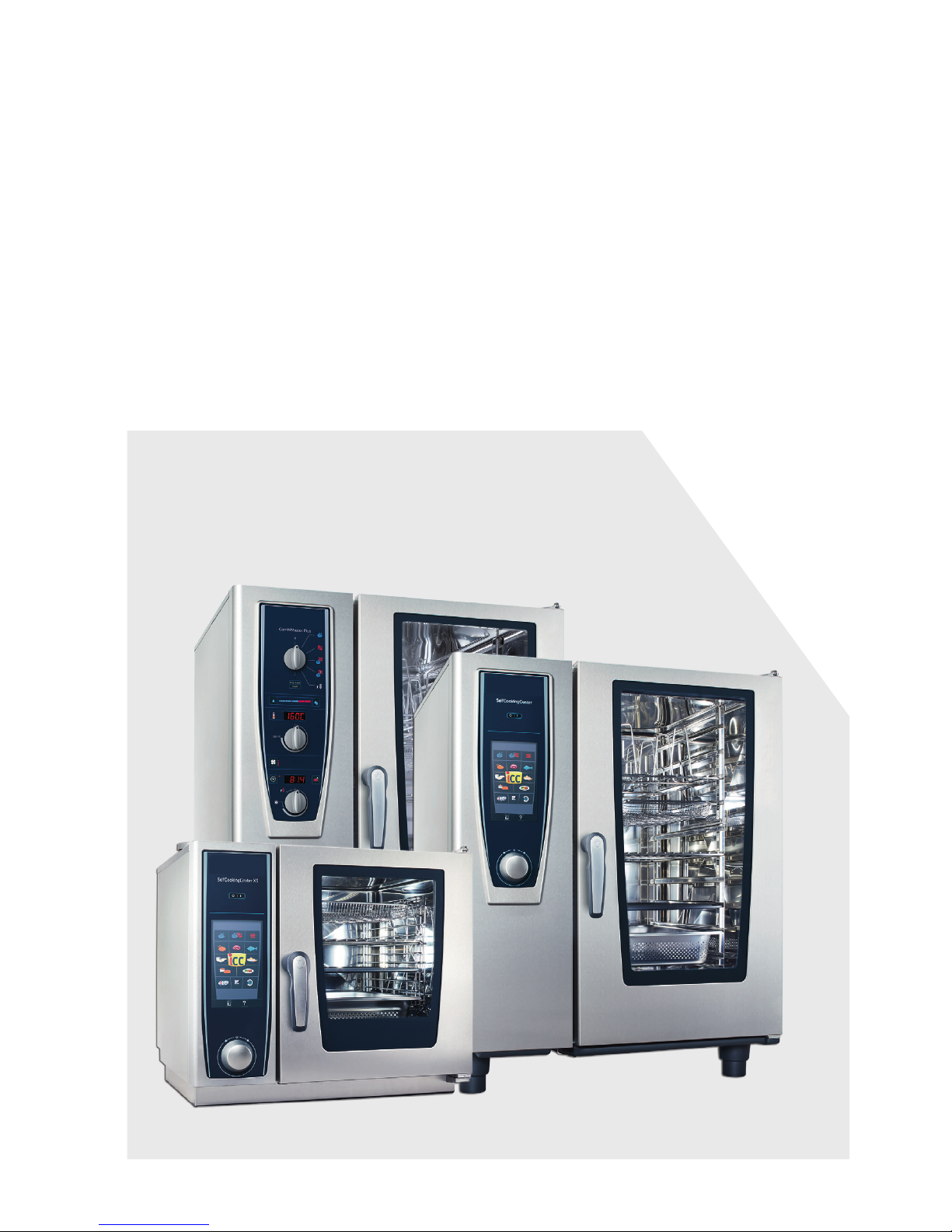
SelfCookingCenter®
CombiMaster® Plus
CombiMaster®
Original Installation Manual
Page 2

2
Contents
Contents
Unit type 4
1 Introduction 5
1.1 About this manual 5
1.2 Warnings used 7
1.3 Warranty 8
2 Safety instructions 9
3 Installation instructions 11
4 Unit transportation 13
5 Setting up the unit 16
5.1 Unit dimensions 16
5.2 Minimum distances 18
5.3 Securing the unit 22
5.3.1 Tabletop units 22
5.3.2 Floor units 28
6 Electrical connection 33
6.1 General information 33
6.2 Electrical units 35
6.3 Gas units 35
6.4 Power supply cable 37
6.5 Equipotential bonding (physical earth ground) 38
6.6 Voltage Conversion 39
6.7 Connection values 41
7 Water connection 43
7.1 Prerequisites 43
7.2 Unit water connection 44
7.3 Water treatment 45
7.4 Selecting water filters 46
Page 3

3
8 Gas connection 48
9 Exhaust gas connection 53
10 Wastewater connection 55
11 Ventilation, technical data, heat dissipation 58
12 Initial start-up 60
13 Options 63
14 Conversion tables 72
Contents
Page 4

4
Unit type
_____________________________________
______________________________________
______________________________________
_____________________________________
Dealer
Installer
Specify for all queries:
Appliance model
Unit no.:
Set to gas type:
Your unit was checked by:
Unit type
Unit type
Page 5

5
1 Introduction
1 Introduction
1.1 About this manual
> This installation manual is part of and shipped
with the unit, and contains information on its
safe installation.
> Read this installation manual completely
before installing the unit.
> This installation manual must be kept available
to installers at all times at the installation location.
> Keep this installation manual on hand
throughout the entire life of the unit.
> This installation manual is to be passed on to
any subsequent owners/operators of the unit.
Target group The target group for this installation manual are
knowledgeable technicians who are familiar with
the process of installing and operating the unit.
Illustrations All illustrations in this manual are examples only.
Deviations between these illustrations and the
unit on site are possible.
We reserve the right to make technical changes in the interest of progress!
© 2017 Rational Technical Services. All rights reserved. Forwarding product-specic
information to third parties is prohibited.
Page 6
6
1 Introduction
This manual applies to the following units:
> all SelfCookingCenter® WE units
> SelfCookingCenter® XS
> all CombiMaster® Plus units
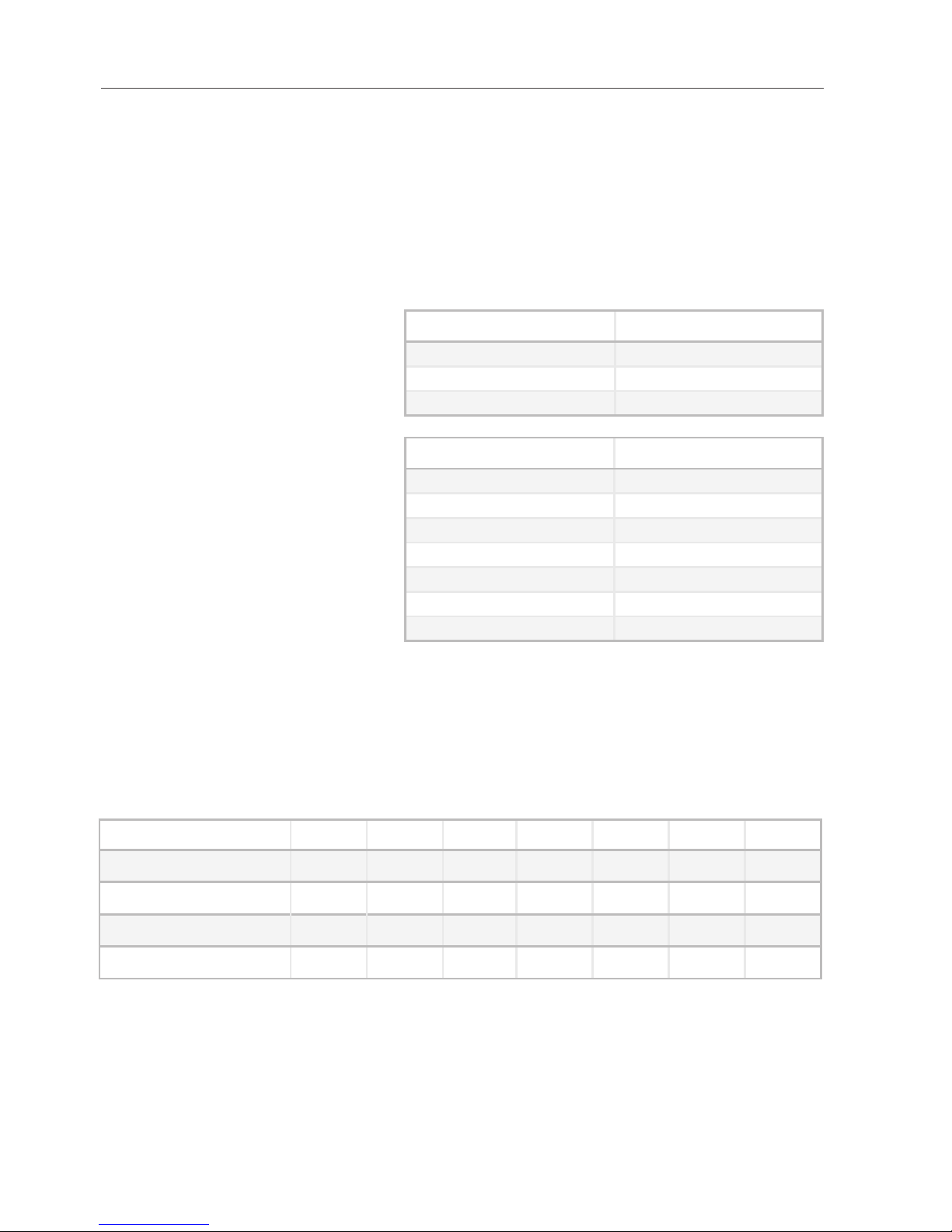
Abbreviations used in this manual:
Product name Abbreviation used
SelfCookingCenter® WE SCC
SelfCookingCenter® XS SCC
CombiMaster® Plus CMP
Appliance size Abbreviation used
6 x 2/3 GN 60
6 x 1/1 GN 61
6 x 2/1 GN 62
10 x 1/1 GN 11
10 x 2/1 GN 12
20 x 1/1 GN 21
20 x 2/1 GN 22
Unit sizes 60, 61, 62, 11, and 12 are referred to collectively as tabletop units.
Unit sizes 21 and 22 are referred to collectively as floor units.
Device overview:
60 61 62 11 12 21 22
SCC Elektro
x x x x x x x
SCC Gas
x x x x x x
CMP Elektro
x x x x x x x
CMP Gas
x x x x x x
Page 7
7
1 Introduction
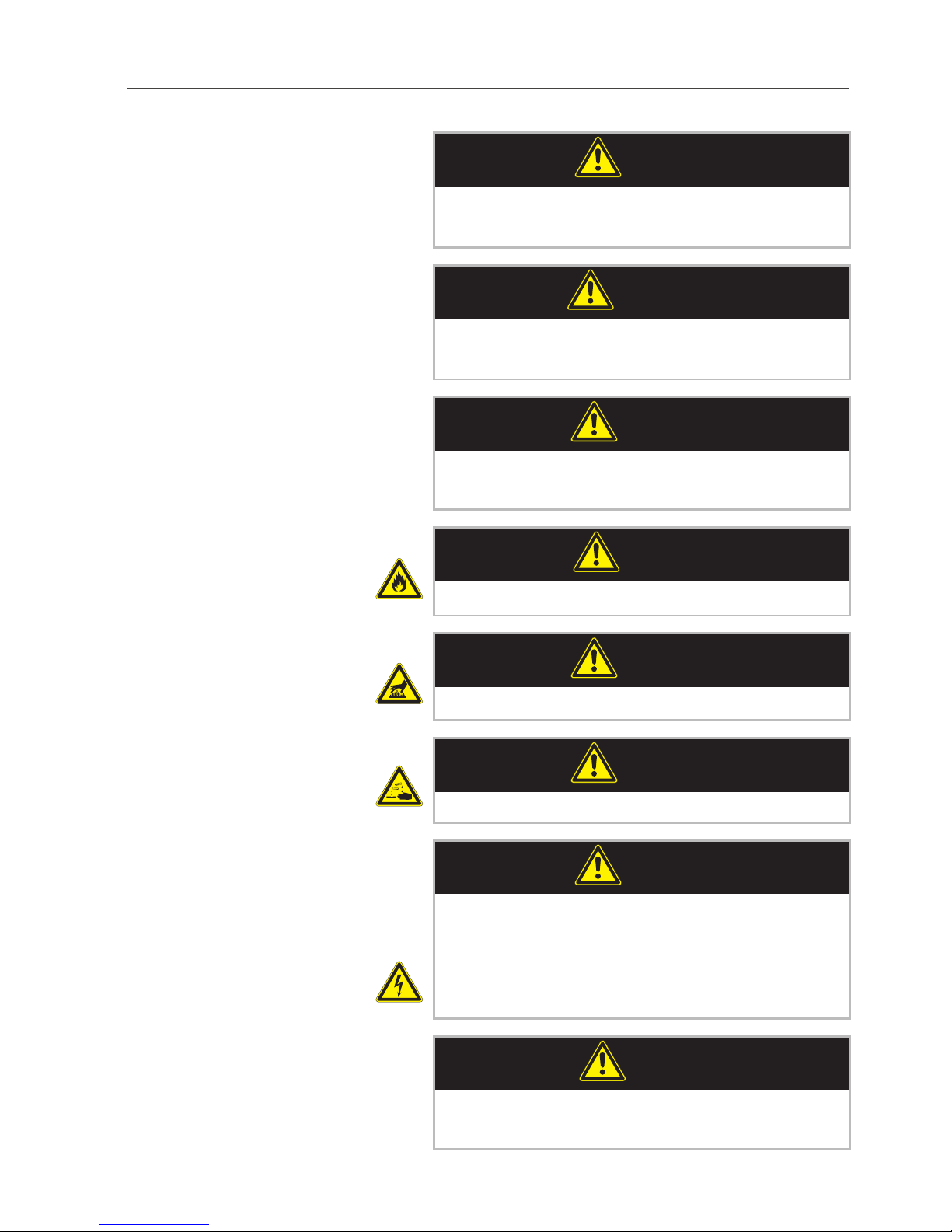
1.2 Warnings used
DANGER
Hazardous situation that may result in severe
injury or death.
WARNING
Hazardous situation that could potentially
result in serious injury or death.
CAUTION
Hazardous situation that could result in minor
injury.
CAUTION
Fire hazard!
CAUTION
Danger of burns!
CAUTION
Corrosive chemical substances!
DANGER
High voltage.
Caution, danger to life
Non-compliance can result in severe injury or
death.
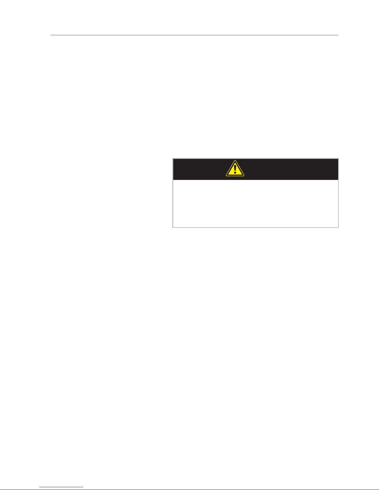
NOTICE
Non-compliance may result in material damage.
Page 8

8
1 Introduction
1.3 Warranty
Exceptions to the warranty include
> Damage to glass, light bulbs and gaskets,
> Damage resulting from improper use, installa-
tion, maintenance, repair or descaling,
> Use of the unit for purposes other than those
for which it is intended,
> Modifications or technical alterations to the
unit not authorized in writing by the manufacturer,
> Usage of non manufacturer-original service
components,
> Damage resulting from failure to observe the
installation instructions in this manual.
Page 9
9
2 Safety instructions
2 Safety instructions
Incorrect installation > Incorrect installation, service, maintenance
or cleaning of this unit can result in damage,
injury or death, as can modifications to the
unit. Read the installation manual carefully
prior to installation.
Unit usage > The unit may only be used for purposes of
cooking food in commercial kitchens. All other
uses are counter to its intended purpose, and
may be dangerous.
Gas appliances
WARNING
Combustion gases!
When installing under an exhaust hood: Ensure
to switch the exhaust hood on when the unit is
in operation and it is operational.
> Do not place anything near or atop the unit’s
exhaust pipes.
Page 10
10
2 Safety instructions
Operating personnel > This unit must not be used by children or by
persons with reduced physical, sensory or
mental capabilities, or by persons with insufficient experience and/or knowledge, unless
such persons are under the supervision of
another person who takes responsibility for
their safety.
> To avoid accidents or damage to the unit, it is
imperative that operating personnel receive
regular training and safety instructions.
Explosion hazard
WARNING
Explosion hazard
If you smell gas:
> Shut off gas supply immediately,
> Do not turn on or off any electrical switching
devices,
> Ventilate the room well,
> Avoid any open flames or sparks,
> Use a telephone outside the affected ares to
inform the gas provider immediately. If the
gas provider cannot be reached, call the local
fire department.
Page 11

11
3 Installation instructions
3 Installation instructions
Standards > Local and country-specic standards and reg-
ulations regarding the installation and operation of commercial cooking appliances must
be observed at all times.
> In all other countries, the corresponding
country-specic standards and regulations
are to be observed.
Liability / Warranty > Damage occurring as a result of non-compli-
ance with installation instructions is excluded
from the warranty.
> Installations and repairs not carried out by
authorized professionals or not using original
spare parts, and technical modications to
the unit which are not approved by the manufacturer in writing, void the manufacturer’s
warranty and product liability.
Conformity > Unit conformity is in reference to the overall
unit at the time of delivery. The operator is
responsible for ensuring extended conformity following any expansions/connection of
additional functions.
Connection work > The necessary connections (water, electricity,
drain and gas) must only be set up by trained
professionals in accordance with local regulations.
Prior to installation > Check the unit for transport damage.
If you suspect the unit has been damaged in
transit, contact your dealer/freight forwarder
immediately! Ensure to note damage at time
of delivery on bill of lading with the driver.
Disposing of old appliances > When the unit reaches the end of its service
life, it must not be taken to a municipal collection point for trash or used electrical appliances. Please conntact your service provider
for disposal.
Page 12
12
3 Installation instructions
Air lter maintenance: > The unit automatically detects dirty air filters.
It will display a service prompt instructing you
to clean or replace the air filter.
> Never operate the unit without the air filter.
When replacing the air filter, please note:
Tabletop units The user may replace the air filter. To replace the
air filter, carefully latch the new filter into the
correct position. Follow the instructions in the
Building Equipment and Appliances chapter of
the user’s manual.
Unit size 60 Air filter part number: 40.04.771
Unit sizes 61, 62, 11 and 12 Air filter part number: 40.02.684
Floor units Air lters on these units must only be replaced by
authorized service partners.
i
NOTICE
Water protection class and reach-through protection on floor units are only guaranteed if air
filter and cover are correctly installed.
Page 13
13
4 Unit transportation
4 Unit transportation
CAUTION
Risk of injury!
Unit may tip over.
When transporting: Secure the unit against
tipping.
21, 22: are top heavy.
CAUTION
Risk of injury!
Note unit weights.
Use lifting aids.
Wear safety shoes.
Weight (without packaging)
60 61 62 11 12 21 22
SCC Electro [kg] 72 111 145 136 189 266 343
SCC Electro [lb] 159 245 320 300 417 586 756
SCC Gas [kg] 130 173 159 205 294 381
SCC Gas [lb] 287 381 351 452 648 840
CMP Electro [kg] 62 103 147 132 182 254 334
CMP Electro [lb] 137 227 324 291 401 560 736
CMP Gas [kg] 114 160 143 196 284 354
CMP Gas [lb] 251 353 315 432 626 780
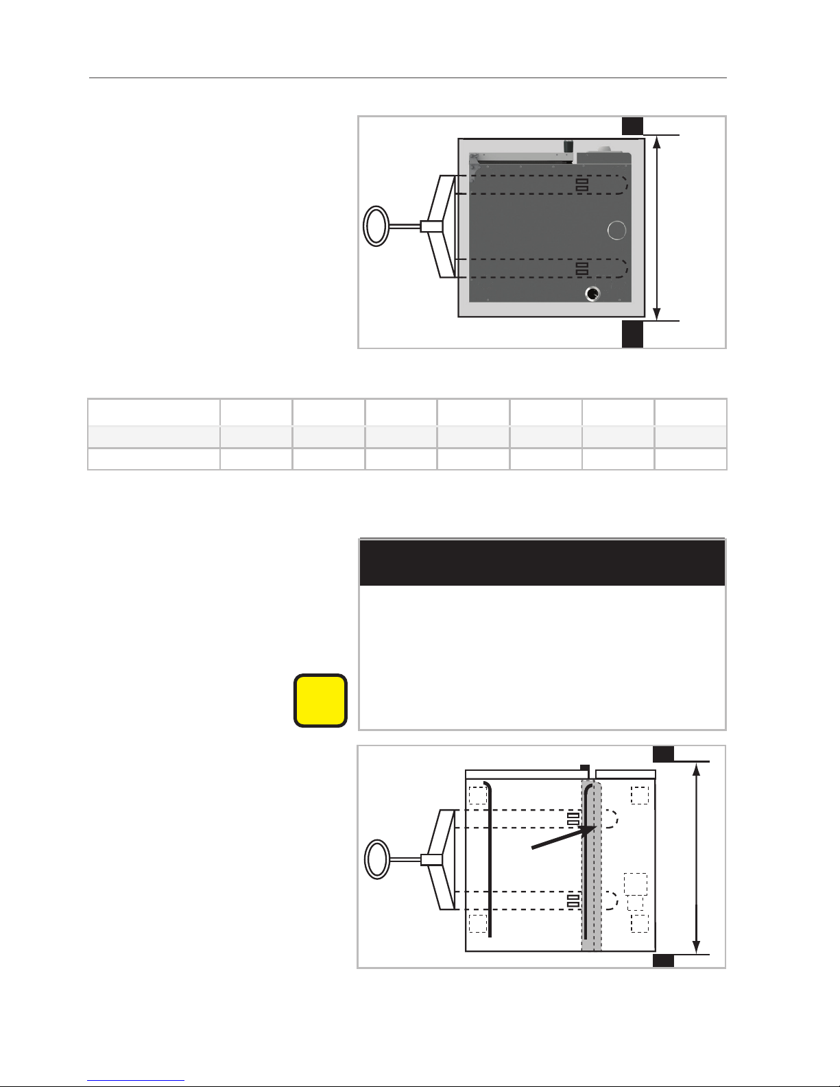
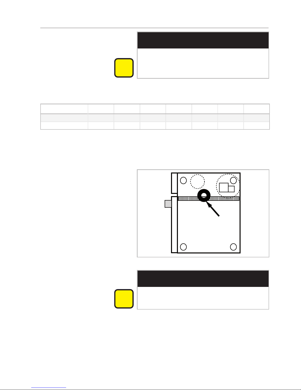
Unit size 60
i
NOTICE
Risk of damage to the unit!
When transporting unit, ensure that air filter
box and USB port remain undamaged.
Page 14
14
4 Unit transportation
Transporting unit with pallet:
x
Note required door width:
Appliance size 60 61 62 11 12 21 22
x [mm] 880 920 1120 920 1120 950 1150
x [Inch] 34 3/4 36 1/4 44 1/8 36 1/4 44 1/8 37 1/2 45 1/4
Transporting unit without pallet:
i
NOTICE
Risk of damage to the unit!
Only floor units may be transported without a
pallet using pallet truck.
Lay wooden beams underneath in grey area
(see arrow).
x
Page 15
15
4 Unit transportation
i
NOTICE
Risk of damage to the unit!
Tabletop units not secured with a pallet should
only be transported using carrying straps.
Note required entrance width:
Appliance size 60 61 62 11 12 21 22
x [mm] 630 845 1045 845 1045 925 1145
x [Inch] 24 6/8 33 1/4 41 1/8 33 1/4 41 1/8 36 3/8 45 1/8
Center of gravity Keep the unit’s center of gravity in mind to pre-
vent it from tipping over (especially unit sizes 21,
22).
i
NOTICE
Risk of damage to the unit!
Note height of entrances.
Page 16

16
5 Setting up the unit
5 Setting up the unit
5.1 Unit dimensions
xy
z
xy
z
xy
z
Page 17
17
5 Setting up the unit
Width x 60 61 62 11 12 21 22
SCC, CMP [mm] 657 847 1069 847 1069 879 1084
SCC, CMP [Inch] 25 7/8 33 3/8 42 1/8 33 3/8 42 1/8 34 5/8 42 5/8
Depth y 60 61 62 11 12 21 22
SCC, CMP [mm] 623 843 1043 843 1043 909 1114
SCC, CMP [Inch] 24 1/2 33 1/4 41 1/8 33 1/4 41 1/8 35 3/4 43 7/8
Height z 60 61 62 11 12 21 22
SCC, CMP el. [mm] 598 832 832 1092 1092 1842 1842
SCC, CMP el. [Inch] 23 1/2 32 3/4 32 3/4 43 43 72 1/2 72 1/2
SCC, CMP gas [mm] 832 832 1092 1092 1842 1855
SCC, CMP gas [Inch] 32 3/4 32 3/4 43 43 72 1/2 73
Page 18
18
5 Setting up the unit
5.2 Minimum distances
i
NOTICE
Unit overheating may cause material and unit
damage!
If the ambient temperature to the left of the
unit becomes too high, it may trigger an emergency shutdown of the unit.
i
NOTICE
Unit overheating may cause material and unit
damage!
Do not install fryers to the rear of the unit.
i
NOTICE
Frost may cause unit damage!
Only install units in frost-proof rooms.
Minimum distance to walls
x
x
y
Appliance size 60 61 62 11 12 21 22
x [mm] 10 50 50 50 50 50 50
x [Inch] 1/2 2 2 2 2 2 2
y [mm] 10 50 50 50 50 500 500
y [Inch] 1/2 2 2 2 2 20 20
Page 19

19
5 Setting up the unit
Recommendation At least 20” [500 mm] away from left side of the
unit so that service work can be performed.
500 mm
/20"
Minimum distance to other units Minimum 14” [350 mm] distance between left
side of the unit and heat sources.
350 mm/
14”
Heat shield To reduce thermo loads to the unit heat shields
can be used (see options).
Page 20
20
5 Setting up the unit
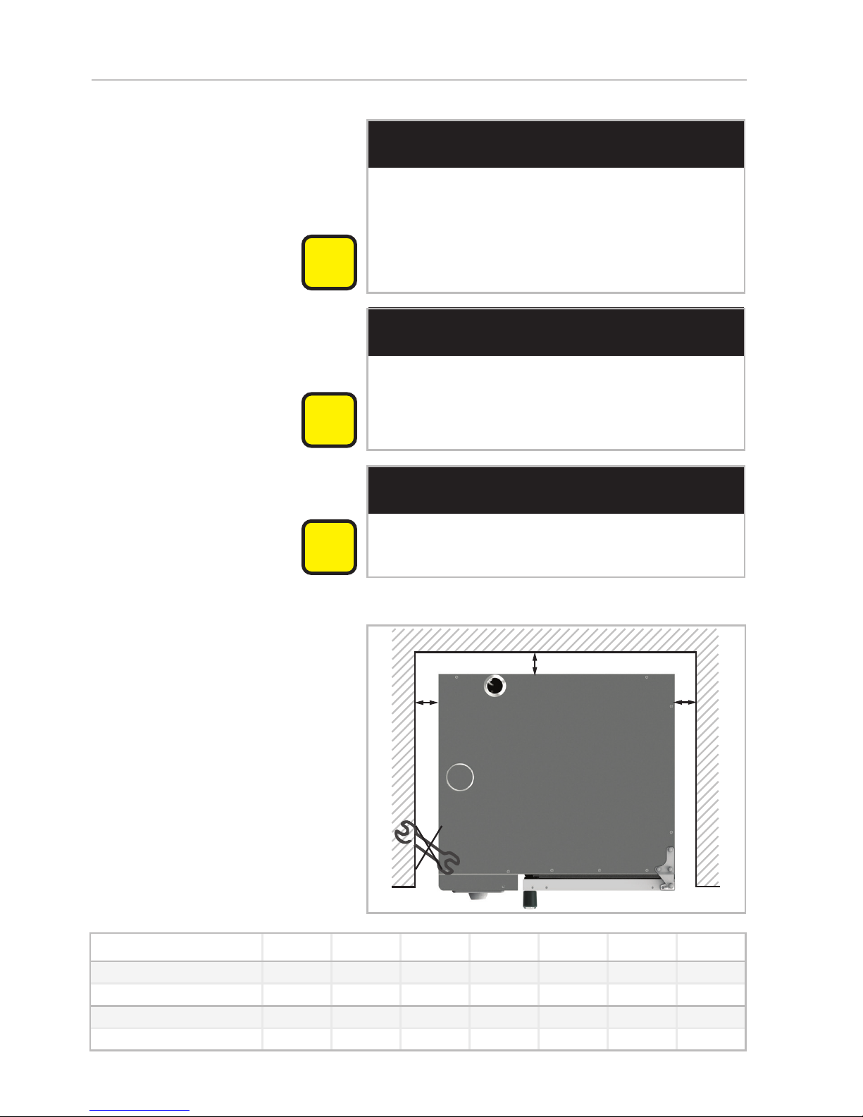
Minimum distance to ceiling
CAUTION
Fire hazard!
Keep minimum clearance between unit and
ceiling.
Gas units: Recommended 16” (400 mm) clearance from
unobstructed rear exhaust pipes and any surface
collecting grease or flammable material.
LEFT SIDE VIEW
minimum
clearance 16“
Gas unit
Page 21
21
5 Setting up the unit
Electric units: Recommended 10” (254 mm) clearance from
unobstructed rear vent pipes and any surface collecting grease or flammable material.
LEFT SIDE VIEW
Electric unit
minimum
clearance 10“
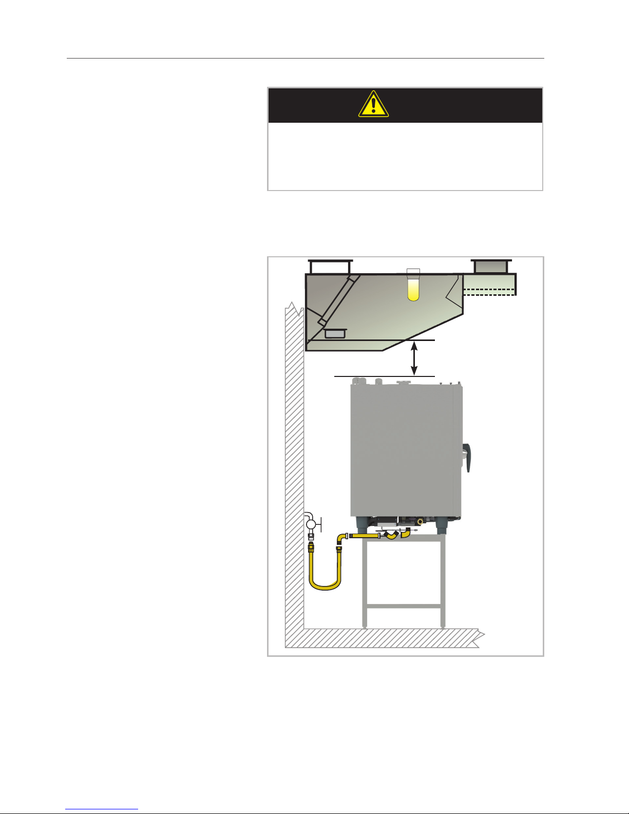
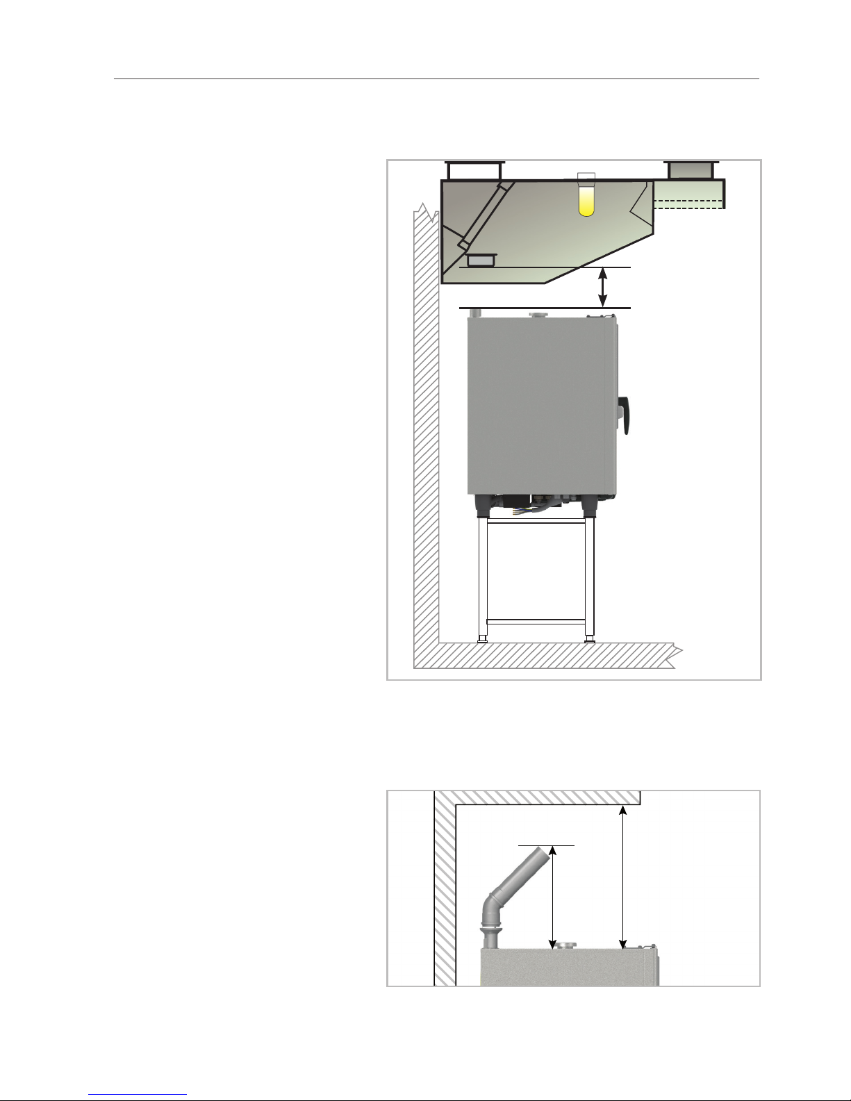
If steam from the venting pipe cannot be direct-
ed into an exhaust hood or a ventilating ceiling,
there must be at least 20” [500 mm] clearance
space above the unit.
min. 20”
[500 mm]
min. 18”
[460mm]
Page 22
22
5 Setting up the unit
Condensation breaker This clearance space is sufficient to install a
condensation breaker so that exhaust air can be
directed into non-critical areas.
Other
i
NOTICE
Unit malfunction!
Avoid steam or grease sources near the cooling air filter. Moisture intake may result in unit
malfunctions.
5.3 Securing the unit
5.3.1 Tabletop units
For safety reasons, tabletop units should only be
placed atop a manufacturer-original oven stand
or base unit. Maximum working height for the
topmost rack is 63” [1600 mm].
Unit size 60 These units do not have height-adjustable feet;
instead, they are set up directly on the installation surface.
The installation surface must be level, clean and
free of grease. Unevenness across the width of
the unit must be no greater than 0.04” [1 mm].
A sealant band is affixed to the underside of the
unit to seal the installation site. This prevents dirt
from getting underneath the unit. When moving
the unit, take care not to damage this seal.
Mounting onto an oven stand:
Insert the two included neoprene blind rivet nuts
into the holes in the rear part of the underbody.
Place the unit onto the oven stand.
Secure in place using the screws provided.
Page 23
23
5 Setting up the unit
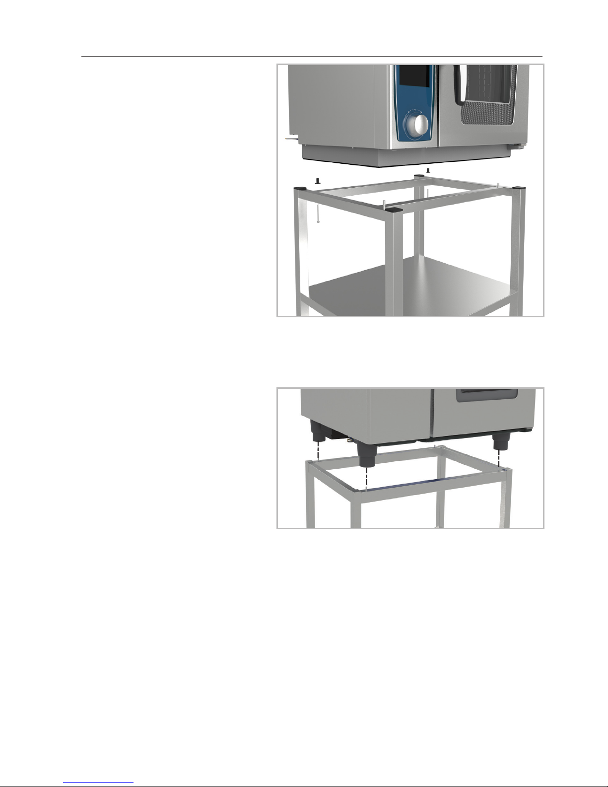
Unit sizes 61, 62, 11, 12 > Place the unit onto the stand. Catching the
feet of the unit in place using the locating pins
on the stand.
Page 24

24
5 Setting up the unit
> Level the unit using the unit feet.
+/- 10 mm
Gas appliances:
WARNING
Risk of damage / injury!
Secure the gas unit against movement.
Installing onto an original oven stand:
> use the mounting kit (article number
8700.0317) to attach the stand to the floor,
either with screws and dowels or with the
special adhesive provided.
64,5 mm
2 5/8"
Page 25

25
5 Setting up the unit
A
Appliance size 61 / 11 62 / 12
A [mm] 745.5 965.5
A [Inch] 29 3/8 38
i
NOTICE
Oven stand mounting kit is not included in
delivery and must be ordered separately.
> Insert the oven stand into the foot locks and
set the stand up horizontally in the installation
location.
Securing a gas appliance:
Installing onto an original oven stand, a work
table or onto the kitchen floor (e.g., Combi-Duo):
> Connect unit feet with foot locks
Article number: 12.00.519 (1x)
Article number: 60.70.463 (set of 4)
1 Unscrew the lower part of the feet
2 Push the retaining plates into the bases and
secure using the nuts provided
3 Screw the bases back in with the retaining
plates in place
4 Adjust all four feet to same length.
Page 26

26
5 Setting up the unit
> Secure the retaining plates to the installation
site using screws and dowels or nuts and
bolts.
i
NOTICE
Oven stand foot locks are not included in
delivery and must be ordered separately.
Movable oven stands/base units:
i
NOTICE
Oven stand foot locks are included in delivery
with movable oven stand.
WARNING
Risk of damage / injury!
Damage to electrical, gas, water and drain
lines.
When mounting onto a rolling base unit or
movable oven stand or movable on castored
Combi-Duo, secure additionally with an
approved chain shorter than the gas line to
prevent excess movement.
Page 27

27
5 Setting up the unit
Lorem ipsum
Page 28

28
5 Setting up the unit
5.3.2 Floor units
Make sure the unit is level.
10 mm
Secure the unit against movement. The enclosed
mounting kit may be used to do this.
64,5 mm
2 5/8"
A
Appliance size 21 22
A [mm] 732.5 937.5
A [Inch] 28 7/8 37
Page 29

29
5 Setting up the unit
If using the mounting kit, push the floor unit into
the foot locks.
Mobil oven racks Make sure the mobile oven rack is positioned
level within the unit.
i
NOTICE
Incorrectly aligning the oven rack may cause
the unit to malfunction (e.g., during cleaning).
Page 30

30
5 Setting up the unit
Make sure there is 7 7/8” [200 mm] distance
between the upper edge of the entry ramp and
the floor with the unit feet.
200 mm
(7 7/8“)
max 4°
Check the cooking cabinet door seal:
Valid for SCC
> activate the “Rinse Without Tabs” cleaning
program,
> observe for excess leakage,
> adjust door as needed.
Valid for
CMP:
> activate the interim cleaning (CLE3) cleaning
programme.
> observe for excess leakage,
> adjust door as needed.
Entry ramp If the floor is uneven, use an entry ramp to com-
pensate for the unevenness. The approach angle
must be no greater than 4°.
WARNING
Scalding hazard!
Hot cooking liquid
Exceeding the approach angle can result in hot
cooking liquid spilling over from cooking containers.
Page 31

31
5 Setting up the unit
Drain troughs in front of floor units:
Position flat plates over the trough in front of the
mobile oven rack.
Handle storage The included holder provides a convenient place
to store the mobile oven rack handle during
cooking. Remove the left side panel to mount the
holder. Insert the holder onto the left side panel
of the unit. Then attach the handle.
Page 32

32
5 Setting up the unit
NSF cover panel For hygiene reasons and in accordance with NSF
Standard 4 and DIN EN 203-3, a cover panel
must be installed over the drain valve and cleaning pump on units 21 and 22.
This cover is included with the unit.
i
NOTICE
This does not apply to 21, 22 mobile units.
Page 33

33
6 Electrical connection
6 Electrical connection
DANGER
Electrocution hazard!
High voltage.
Observe local and NEMA/NEC regulations
during installation!
WARNING
Danger to life!
Incorrect connection may result in electric
shock!
Note color coding of wires!
Color coding of wires:
yellow/green = electrical ground,
blue = neutral conductor (only 61, 11, 21 gas)
brown, red, orange or black = phase L1, L2, L3
i
NOTICE
Improper connection can cause damage to the
unit (e.g., fan motor).
6.1 General information
Only connect the unit in accordance with the
installation instructions and the information on
the rating label.
Connect the unit to a standard power supply in
accordance with the applicable regulations.
Observe all local regulations and standards,
which must conform to national, state and local
code requirements!
The appliance is equipped with a motor with an
integrated frequency converter.
Connect the device to a GFCI Type B (ground
fault circuit interrupter).
Applicable standards: NFPA 70/NEC, CSA C22.2
Page 34

34
6 Electrical connection
CAUTION
Improper installation can lead to personal injury or property damage!
Customer: provide accessible all-pole disconnect unit with at least 3 mm contact separation
(disconnect switch or circuit breaker).
If unit must be connected to an earth leakage
circuit breaker, consult with the NEC code for
specific values according to KW of attached load
for selection of valves.
Before disconnecting unit or reconnecting it
again be sure the unit is switched off prior.
Remove the left side panel to access the connec-
tion port.
Removing the left side panel > Remove the two screws on the bottom of the
left side panel.
> Pull the left side panel down from the unit.
> Remove the left side panel.
Page 35

35
6 Electrical connection
Units 12, 21 and 22 Electro: Maximum connection impedance at the grid con-
nection point is 0.09Ω.
The cross-sections of the connection lines
depend on current consumption and local regulations.
Special voltage available on request.
6.2 Electrical units
Each unit should have its own protected power
supply connection.
Each unit has its own switched disconnection for
safety.
For connection use power cord that is recom-
mended in NEC/NEMA standard.
Unit size 60 are delivered with power cable and angled plug:
2AC208 and 2AC240: 6-50P 40.05.267
3AC208 and 3AC240: 15-30P 40.05.268
Unit size 61 - 22 are delivered without power cable.
Cable connection point The main fuse (tabletop units) or connection ter-
minal (floor units) is behind the removable left
side panel inside the electrical compartment.
6.3 Gas units
We recommend that each unit have its own pro-
tected supply line.
Either a fixed connection or a plug connection
may be used to connect the unit to the power
supply.
All gas units are delivered with an approximately
8 ft [2.5m] connection cable with plug
120V units: 5-15P
208V units: 6-15P.
i
NOTICE
Non-functioning unit!
Note polarity of electrical connection! Burners
will not function if polarity is incorrect.
Page 36

36
6 Electrical connection
i
NOTICE
Connection to a residential type GFI (Ground
Fault Interrupter) of insufficient leakage current
is not advisable.
Random and or nuisance trips of the breaker
could result.
Page 37

37
6 Electrical connection
6.4 Power supply cable
i
NOTICE
In order to avoid hazards, the mains power
cable may only be replaced by the manufacturer, its customer service representative or similarly qualified service personnel.
i
NOTICE
Non-functioning unit !
Tighten mains lead connection.
Use copper wire only for power supply connec-
tions of connect size.
Electrical units: Connect a supply cable of at least Type NEC UL
standard and tighten the mains lead connection.
Connect the cable according to the following
diagram:
Gray connector terminals:
L1, L2, L3 (independent of rotary field).
Yellow-green connector terminals: electrical
ground connection.
Gas units: Should the connection line need to be replaced
as part of service work, use a cable of quality no
less than SGO or SJTOW or equivalent (original
rating) 14-2 plus ground.
For plug type reference NEMA.
5-15P 120V IP for 61/101/201
6-15P 208/240V IP for 62/102/201
this is also an option on 61/101/201
Page 38

38
6 Electrical connection
6.5 Equipotential bonding (physical earth ground)
A connection site for optional equipotential
bonding is located on the bottom or the back of
the unit.
60:
61, 62, 11, 12:
21, 22:
Page 39

39
6 Electrical connection
6.6 Voltage Conversion
208/240V units All electric units and 62/102/202 gas units are
set to 208V ex works. They can be converted to
240V.
To convert from 208V to 240V proceed as follows:
> Disconnect unit from mains
> Remove left side panel and open operator
panel.
> Set power switch S13 to desired voltage (208
or 240V)
> On the control transformer T1 change con-
nection to the desired voltage input (208 or
240V)
> In the starter kit of the unit there is a sticker
which has to be filled in after voltage conversion. After filling it in put the sticker next to
the type plate.
60:
Page 40

40
6 Electrical connection
61-22:
S 13
440/480 V units Units are set to 480V ex works, but can be con-
verted to 440V.
To convert from 480V to 440V proceed as follows:
> Disconnect unit from mains
> Remove left side panel and open operator
panel.
> Remove adapter cable W22 from input trans-
former T3 and plug X72.
> Connect plug X72 to transformer T3.
> Set power input switch S13 to 440 V
Page 41

41
6 Electrical connection
6.7 Connection values
SCC, CM_P Electrical units
Appliance size 60 61 62 11 12 21 22
Power [kW] /
Current consumption [A]
Input voltage
2 AC 208V 5,7 /
27.5
11,1 /
53,4
2 AC 240V 5,7 /
31.5
11,1 /
61,5
3 AC 208V 5,7 /
16.5
11,1 /
30,8
22,1 /
61,4
19 /
52,8
37 /
102,7
38 /
105,6
68/
189
3 AC 240V 5,7/
19
11,1 /
35,5
22,1 /
70,8
19 /
60,9
37/
118,6
38 /
121,8
68 /
218
3 AC 440V 11,1 /
14,6
22,1 /
33,3
19 /
24,9
37 /
48,6
38 /
49,9
68 /
83,9
3 AC 480V 11,1 /
15,8
22,1/2919/
27
37/
52,6
38 /
54
68 /
96,7
SCC_WE, CM_P Gas units
Appliance size 61 62 11 12 21 22
Power [kW] /
Current consumption [A]
Input voltage
1NAC 120V 0,4 /
3,33
0,5 /
4,17
0,95 /
7,9 2
1NAC 208V 0,4 /
1,92
0,77 /
3,7
0,5 /
2,4
0,8 /
3,85
0,95 /
4,57
1,6 /
7,69
1NAC 240V 0,4 /
1,66
0,77 /
3,21
0,5 /
2,1
0,8 /
3,33
0,95 /
3,96
1,6 /
6,66
Page 42

42
6 Electrical connection
Fuse [A]
60 61 62 11 12 21 22
2 AC 208V 50 60
2 AC 240V 50 70
3 AC 208V 30 35 70 60 125 125 200
3 AC 240V 30 40 80 75 150 150 250
3 AC 440V 20 35 30 60 60 100
3 AC 480V 25 40 35 70 70 110
AWG [x]
60 61 62 11 12 21 22
2 AC 208V 8 4
2 AC 240V 8 4
3 AC 208V 12 8 3 4 2 1 4/0
3 AC 240V 12 8 3 4 2 1 3/0
3 AC 440V 14 8 8 4 4 2
3 AC 480V 14 8 8 4 4 3
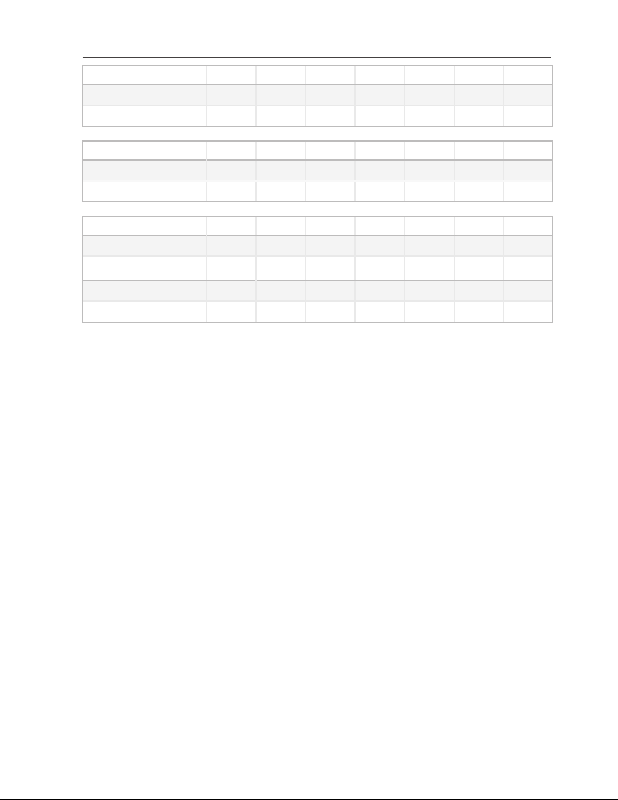
Maximum permissible tolerance for input voltage (see type label for input voltage) is
within the range of -15% to + 10%.
Use copper wire only for power supply connections.
Page 43

43
7 Water connection
7 Water connection
The unit complies with all relevant regulations
(SVGW, KIWA, WRAS).
7.1 Prerequisites
> The user must supply each unit with its own
water supply tap.
> Rinse the water supply line before connecting
the unit to water!
> Water pressure 21 - 87psi, 43psi recom-
mended.
> Flow rates required for each unit (max.):
Appliance size 60 61 62 11 12 21 22
[gal/min] 1,8 5,2 6,6 5,2 6,6 6,6 6,6
Connect the unit to drinking water-quality water.
Install the unit with adequate backflow protec-
tion to comply with applicable federal, state, and
local plumbing codes.
Connect a flexible drinking-water connection
hose in accordance with EN 61770 / IEC 61770
or of similar quality. Take any necessary safety
precautions with the water tap, such as backflow
preventers as required by local code. (Not supplied by manufacturer)
The water connection hose must comply with
country-specific hygiene standards for drinking
water hoses.
Use only new hoses as water connections. Do
not re-use old hoses.
i
NOTICE
Non-functioning unit!
Ensure that the minimum water conductivity
value of 50µS/cm (Micro Siemens) is maintained.
Ref: reverse osmosis treatment.
Page 44

44
7 Water connection
7.2 Unit water connection
Unit size 60:
1
Unit sizes 61, 62, 11, 12:
1
2
3
Unit sizes 21, 22:
3
2
1
Water connection legend 1 = 3/4” common water supply line.
(cold water up to 30°C [86°F])
61, 62, 11, 12, 21, 22: If split water connection:
2 = 3/4” cold water supply line (max. 30°C
[86°F]).
3 = 3/4” treated water supply line (max 30°C
[86°F]) (steam generator, hand shower, SCC
only: additional humidification, cleaning).
Page 45

45
7 Water connection
i
NOTICE
Unit size 60 is single water connection only.
All others are for split water connection.
i
NOTICE
All units are provided with BSP to garden hose
thread adapter(s) in starter kit.
article number: 50.00.790
i
NOTICE
The manufacturer recommends preventative
inspection be conducted around six months
after unit commissioning to ascertain the
degree of limescale buildup in the steam generator, especially for CMP/CM units.
This inspection should be performed by a
trained technician.
7.3 Water treatment
> The water connection must not use treated
water with hardness below 5.2 gr/gal, as
such water is aggressive and corrosive, and
can shorten the lifespan of the unit.
> Connecting the SCC to water with hardness
below 7.3 gr/gal:
When the self-test begins, the system will
prompt the user to indicate the hardness of
the water the unit is connected to. Select
“Water hardness below 7.3 gr/gal “treated
water”.
> Observe all country-specific regulations
Page 46

46
7 Water connection
regarding water and sewer connections, especially those regarding installation of water
intake points.
Only USA (not valid for CAN) In most cases, water connections do not require
additional filters or water treatment.
Filtration and/or water treatment (A, B, C, D)
may be necessary if water conditions are critical.
Contact the local water supply company to
inquire about water chloride levels (Cl–), chlorine
levels (Cl2) and hardness.
7.4 Selectingwaterlters
A) Fine filters We recommend fine filters with fineness of 5 -
15µm for filtering water contaminated with sand,
iron particles or suspended matter.
B) Active carbon filters If water contains high levels of chlorine Cl2 (over
0.2mg/l, corresponds to 0.2ppm; information
provided by water supply company), (typically
municiple supplied water).
C) Reverse osmosis system Due to corrosion risks, a reverse osmosis system
must be used if and only if chloride (Cl–) concentrations are above 80mg/l (corresponds to
80ppm, information provided by water supply
company).
Note: Ensure that the minimum conductivity
value of 50µS/cm (Micro Siemens) is being
maintained.
D) Water softening:
SCC: When used properly, these units remove lime
from water completely independently, so upscale
water softening is not necessary.
CMP: Recommended for treating water if severe calci-
fication occurs (without chloride contamination).
Systems: Weak acid decarbonization (H+ ion
exchange).
Sodium ion exchangers (as are commonly found
in dishwashers) are not recommended.
Phosphate metering is also not recommended
due to its negative effects on the water system.
Page 47

47
7 Water connection
Important for treated water connections:
To increase filter capacity, split the water con-
nection like shown in chapter 7.2 into cold and
treated water inputs (not possible with size 60
units) - remove the common water supply line.
i
NOTICE
Unit size 60 is single water connection only.
All others are for split water connection.
Filter size sufficient for:
Average treated water consumption
(without hose shower) at max. flow rate of
4,3gal/min.
Average Treated Water Consumption:
Appliance size 60 61 62 11 12 21 22
[gal/h] N/A 0,8 2,2 1,7 2,9 3,5 4,2
Important for filter connections: Water hose with minimum interior ø 1/2”.
Filter connection ø 3/4”.
When using a combination of filters, ensure filter
sequence of A-B-C or A-B-D in direction of flow.
Page 48

48
8 Gas connection
8 Gas connection
CAUTION
Danger to life!
Connecting incorrectly may result in burns or
fire.
Observe local regulations.
DANGER
Poisoning hazard!
Make sure that factory settings conform with
actual connection conditions:
> Perform exhaust gas analysis when first
commissioning steam- and convection burners (CO, CO
2
)
> record these values.
If undiluted CO levels are above 150ppm for
convection and 400ppm for steam, a company-trained and certified technician must be
called in to check burner settings in accordance
with setting instructions, and adjust these settings if needed.
Observe all local gas authority regulations!
Check the type of gas available and the dynamic
connection pressure against the values specified
on the unit.
! mbar
Page 49

49
8 Gas connection
i
NOTICE
Any gas equipement like connectors, fittings
and regulators must be designed to supply the
required amount of gas.
Pipe diameter in accordance with local regulations
> at least ¾” ID (interior diameter) for 61-201
> at least 1” ID (interior diameter) for 202
Gas connection internal thread.
Gas shut-off valve on each unit.
Gas connection with gas outlet possible.
Installation must conform to:
CGA-B 149.1 natural gas code,
CGA-B 149.2 propane gas code.
Secure the unit against movement.
Use a suitable gas leak detector to check for
leaks in the gas supply and gas distribution within the unit.
Inner thread of gas connection at unit manifold:
¾”
Adapter Brass elbow BSP to NPT is included in the starter
kit (can be found in the cooking cabinet):
> 70.00.188 ¾” BSP to ¾” NPT for 61 - 201
> 70.01.012 ¾”BSP to 1” NPT for 202
Page 50

50
8 Gas connection
Gas connection 61, 62, 11, 12
¾“ pipe
¾“
main gas line
shut off
LEFT SIDE VIEW
Quick connect gas line i. e.
Dormont 36“ ¾“
Gas connection 21, 22
¾“ pipe for 201
1“ pipe for 202
¾“ for 201
1“ for 202
main gas line
shut off
LEFT SIDE VIEW
Quick connect gas line i. e.
Dormont 36“ ¾“ for 201
1“ for 202
Page 51

51
8 Gas connection
Notes
DANGER
Gas connections must only be set up by locally
authorized gas technicians!
Set up the gas connection line in accordance
with the rated thermal load specified on the
type label.
i
NOTICE
Unit malfunction!
If line pressure deviates from connection flow
pressure, contact gas supply company.
Maintain dynamic flow pressure in range of:
- 6,5“ - 10” w. c. for natural gas
- 10” - 15” w. c. for LPG
Otherwise:
> do not start the unit,
> shut off the gas connection to the unit.
i
NOTICE
Non-functioning unit!
Gas components are designed for maximum
connection pressure of 26” w. c. Higher operating pressures are not permitted and can
damage components.
Page 52

52
8 Gas connection
Gas consumption
Gas type Required
connection
flow pressure
Wobbe index
[MJ/m3]
Maximum consumption at rated thermal load (15°C,
1013mbar)
Wi Ws 61 62 11
NATURAL 6,5 -10,0
in/wc
45,67 50,72 49,44 ft3/h
49000 BTU/hr
107,35 ft3/h
106000 BTU/hr
82,98 ft3/h
83500 BTU/hr
PROPANE 10,0 -15,0
in/wc
74,75 81,19 2,69 lb/h
48200 BTU/hr
5,86 lb/h
103800 BTU/hr
4,61 lb/h
81500 BTU/hr
Gas type Required
connection
flow pressure
Wobbe index
[MJ/m3]
Maximum consumption at rated thermal load (15°C,
1013mbar)
Wi Ws 12 21 22
NATURAL 6,5 -10,0
in/wc
45,67 50,72 171,9 ft3/h
170000 BTU/hr
168,4 ft3/h
167000 BTU/hr
348,2 ft3/h
340000 BTU/hr
PROPANE 10,0 -15,0
in/wc
74,75 81,19 9,5 lb/h
166800 BTU/hr
9,1 lb/h
163000 BTU/hr
18,8 lb/h
333500 BTU/hr
Page 53

53
9 Exhaust gas connection
9 Exhaust gas connection
DANGER
Asphyxiation hazard!
Combustion products (CO and CO
2
)
Prevent unacceptable concentrations of harmful combustion products within the installation
room.
Set up the unit under conditions of adequate
ventilation.
Observe instructions given in the currently valid
versions of all local standards during installation.
For gas exhaust on unit, it must be placed under
an exhaust hood externally vented (observe your
local regulations). Clearance above flue pipes
shall be 16” (400 mm).
Room ventilation The rooms in which these appliances are installed
must be well ventilated, in order to prevent an
unacceptable build-up of harmful combustion
products.
Page 54

54
9 Exhaust gas connection
Maintenance
As per the specified standards, we recommend
gas components undergo annual maintenance.
After maintenance or repair work:
> Check that the compensation tube is posi-
tioned correctly.
> Check the gas supply line components for
leaks.
Exhaust gas and room volumes (specified values apply only to the individual units)
Appliance size 61 62 11 12 21 22
Min. room size with free ventilation [yd3] 68 146,5 115,1 235,5 230,2 470,9
Min. room size with constant ventilation [yd3] 34 73,3 57,6 117,7 115,1 235,4
Min. combustion air supply [yd3/h] 24,9 58,9 45,8 94,2 91,6 188
Max. exhaust gas volumes [yd3/h] 49,7 141,3 102 235,4 196,2 458
Max. exhaust gas temperature [°F] 662 968 878 1094 806 968°F
Free ventilation Combustion air supply through windows and
doors
Constant ventilation Combustion air supply via two ventilation open-
ings to the outside, each with 23 inch2 free cross
section (one near the ceiling, the other near the
floor)
Page 55

55
10 Wastewater connection
10 Wastewater connection
i
NOTICE
Use only steam temperature-resistant pipes
for wastewater drainage (e.g. copper, stainless
steel or schedule 80 PVC).
Do not use hoses.
> Unit complies with all relevant regulations
(SVGW, KIWA, WRAS).
> Welding a drain pipe onto the unit drain is not
permitted (will result in damage to the unit).
> Use 2” pipe (1 1/2” for size 60 units) with a
constant gradient (at least 5% or 3°); do not
reduce pipe diameter.
> Recommended: drain should have 1” air gap
and discharge to a floor sink or receptable.
> Observe drain dimensioning requirements:
steam generator short-term pump-off rate =
0,18 gal/s [0.7l/s]
> Average wastewater temperature: 149°F
(adjustable by trained technician in unit settings)
> Applicable standard: DIN 1986, T1
> We recommend integrating a trap into the
wastewater connection in order to optimize
energy consumption.
Tabletop units > Tabletop units may use either a wall drain and
/or a floor drain
> Each unit must have its own wastewater con-
nection (including Combi-Duo).
Page 56

56
10 Wastewater connection
Unit size 60
min. 3°/5%
Ø 40 mm (1½”)
Unit sizes 61, 62, 11, 12
> Avoid bends attached immediately at unit.
> Provide 8 - 10” before a bend.
weight of piping
not to be placed
on unit drain
Air gap per
local code
Clamped
to stand
approx. 24“
3x45°
2“ copper
pipe
8 - 10”
Page 57

57
10 Wastewater connection
Floor units > Floor units can only use floor drains
Ø 50 mm (2”)
70 mm
(2 3/4“)
max. 1 m (3 ft.)
min. 3°/5%
i
NOTICE
The average height of the water drainage pipe
is 2 3/4” [70 mm].
Options > Additional riser tube to reduce steam escap-
ing from drain pipe with open drain systems.
> Tabletop units:
Increase ground clearance using longer 4”
[110 mm] foot bases and height-adjustable
transport trolley for mobile oven racks.
> Floor units:
Increase ground clearance by raising up unit
and mobile oven rack.
See options; chapter 13.
air gap
air gap
Page 58

58
11 Ventilation, technical data, heat dissipation
11 Ventilation, technical data, heat dissipation
On-site ventilation: When installing an externally vented exhaust
hood, observe the following:
> Comply with all local regulations and stan-
dards (NFPA 96; Gas combi or electric combi
where applicable)
The exhaust hood should protrude 1-1,6 ft
[300-500 mm] over the front of the unit.
> If using a VarioSmoker the unit must be
installed underneath an externally vented
exhaust hood (CO!).
> Install a grease filter into the protruding part
of the exhaust hood.
Accessories Recirculation hoods (UltraVent) are available for
most single table electric units. They can be retrofitted. Consult the hood installation guide for
information on connecting the hood.
i
NOTICE
Asphyxiation hazard!
Flue gases (CO and CO
2
)
Prevent unacceptable concentrations of harmful flue gases within the installation room.
Set up the unit under conditions of adequate
ventilation.
Page 59

59
11 Ventilation, technical data, heat dissipation
Technical data Noise emissions value: <70dBA
Water jet protection: IPX5
Thermal load - SCC units [kJ/h]:
Electrical units 60 61 62 11 12 21 22
latent: 1.020 2.050 3.450 3.450 6.350 6.850 10.900
sensitive: 1.350 2.450 4.450 4.450 7.750 8.850 14.000
Gas appliances 61 62 11 12 21 22
latent: 2.050 3.450 3.450 6.350 6.850 10.900
sensitive: 2.450 4.450 4.450 7.750 8.850 14.000
Thermal load - CMP units [kJ/h]:
Electrical units 60 61 62 11 12 21 22
latent: 1110 2.143 4.167 3.529 6.667 7.200 12.500
sensitive: 1420 2.727 5.000 4.615 9.474 9.000 14.286
Gas appliances 61 62 11 12 21 22
latent: 2.143 4.167 3.529 6.667 7.200 11.583
sensitive: 2.571 5.000 4.286 9.231 8.780 13.636
We reserve the right to make technical developments / modifications.
Page 60

60
12 Initial start-up
12 Initial start-up
WARNING
Scalding hazard!
To avoid scalding, when working with liquids
or foods that become liquid when heated to
higher temperatures, only use containers that
are easy to monitor. (DIN: IEC 60335-2-42).
The “Max. rack height for containers with liquid”
safety decal is included in the starter kit. After
installing the unit, attach the decal at a height of
63” [1600 mm] (see examples).
)(63"1600
)(63"1600
CAUTION
Risk of fire!
Remove packaging and transportation materials, starter kit, grids and containers from the
cooking cabinet.
Page 61

61
12 Initial start-up
Self test When first commissioning a new unit, start a
one-time self-test. This test serves to adjust the
unit to its specific ambient conditions.
It runs automatically, and takes between 45 and
65 minutes depending on the size of the unit; if
an UltraVent is in use, the test will take around
20 minutes longer.
> To perform the self-test, check the hook
latches and the air baffle to ensure they are
seated correctly and no cardboard/plastic is
inside unit.
> The unit must be connected to water, waste-
water, and electricity as per installation
instructions; gas units must also be connected to gas supply and operational ventilation
hood.
> The left side panel must be closed.
> With tabletop units, insert a flat container into
the middle of the rack, with the opening facing down.
> With floor units, insert two containers into
the mobile oven rack: one centered in front of
each fan, with the openings facing down.
> Do not open the cooking cabinet door during
the self-test.
> Self-test must not be interrupted, e.g. by
switching unit off.
Page 62

62
12 Initial start-up
DANGER
Poisoning hazard!
Gas units: perform exhaust gas analysis after
self-test.
SCC: press “Start”
CMP: press “Prog/Start”
Page 63

63
13 Options
13 Options
Left and right heat shields (not suitable for Combi-Duo and UltraVent)
If it is not possible to keep the left side (or right,
on unit sizes 61 and 11) of the unit a sufficient
distance away from heat sources, an additional
heat shield can reduce thermal loads.
i
NOTICE
A clearance of 2” is still required from the heat
shield to the heat source.
50 mm [2“]
Appliance size 61 62 11 12 21 22
Left heat shield 60.70.390 60.70.392 60.70.391 60.70.393 60.70.394 60.70.395
Right heat shield 60.70.736 60.70.743
Page 64

64
13 Options
Adjusting height on unit sizes 61, 62, 11, 12
If units of these sizes do not have sufficient
ground clearance, ground clearance can be
increased using longer foot bases (4” [110 mm]).
To do this, simply replace the standard foot bases
with longer ones.
Article number: Foot extension: 12.00.224
i
NOTICE
Scalding hazard!
The topmost rack rail may then be higher than
63” [1600 mm].
Page 65

65
13 Options
Height adjustable transport trolley for mobile oven rack
When using a mobile oven rack and a mobile
oven rack transport trolley, height differences can
be compensated by using an adjustable transport
trolley.
Appliance size 61, 11 62, 12
Article number: 60.60.188 60.70.160
Page 66

66
13 Options
Raising floor units If ground clearance underneath floor units is too
low, use foot extensions to increase the height of
the unit by 2 3/4” [70 mm].
Article number: 60.21.179 (1x)
Article number: 60.70.407 (set of 4)
i
NOTICE
Scalding hazard!
The topmost rack rail may then be higher than
63” [1600 mm].
Raising mobile oven racks One required per each rack used. When using
foot extensions on floor units, compensate the
height difference on the mobile oven rack using
mobile rack oven elevation 2 3/4” [70 mm].
Appliance size 21 22
Article number: 60.21.184 60.22.184
Page 67

67
13 Options
Floor unit entry ramps If the ground is not level in the mobile oven rack
entry area on floor units, use an entry ramp to
compensate this. The plate feet are adjustable by
+/-1/2” [+/-10 mm].
The entry ramp is attached to the right feet of
the unit using the ramp clamps.
Appliance size 21 22
Article number: 60.21.080 60.22.181
Page 68

68
13 Options
Condensation breaker
i
NOTICE
Unit malfunction!
Extending the ventilation pipe without using
a condensation breaker can cause the unit to
malfunction.
Installing a condensation breaker and the includ-
ed pipes can divert steam escaping from the
exhaust pipe into non-critical areas, or towards the
extraction fan of a ventilation system.
460 mm
[18“]
Appliance size 60 61, 62, 11 12 21, 22
Article number: 60.74.037 60.72.591 60.72.592 60.72.593
Page 69

69
13 Options
Reducing excessive steam emissions
An additional riser pipe can be attached to the
ventilation pipe to reduce excess steam emissions. Holes must be drilled into this extra vent
pipe where air is sucked in and condensates the
steam.
8 mm
1/8"
Ø 1/8“
[8 mm]
4“
[100 mm]
Page 70

70
13 Options
Wall mount Unit sizes 60 and 61 only
The two units named above can be attached to
the wall using a wall mount.
i
NOTICE
Be sure to follow the corresponding modification instructions when performing wall installations.
Appliance size 60 61
Article number: 60.30.968 60.70.963
Page 71

71
13 Options
Interfaces
SCC come with an Ethernet interface as part of their
standard equipment. An CAT-5 Ethernet cable
must be used to connect to a network.
Connection location:
Unit size 60: on the rear of the unit
Unit sizes 61-22: on the underside of the unit
A detailed description on connecting to a net-
work is provided in the user manual.
CMP can optionally be ordered or retrofitted with Eth-
ernet interfaces.
Part number for add-on kit:
60-12: 87.01.419
21-22: 87.01.420
Page 72

72
14 Conversion tables
14 Conversion tables
°dH °f °e ppm mmol/l gr/
gal(US)
mval/kg
1 °dH 1 1.79 1.25 17.9 0.1783 1.044 0.357
1 °f 0.56 1 0.70 10.0 0.1 0.584 0.2
1 °e 0.8 1.43 1 14.32 0.14 0.84 0.286
1 ppm 0.056 0.1 0.07 1 0.01 0.0584 0.02
1 mmol/l 5.6 0.001 0.0007 100 1 0.00058 2
1 gr/gal (US) 0.96 1.71 1.20 17.1 0.171 1 0.342
1 mval/kg 2.8 5.0 3.5 50 0.5 2.922 1
CaO[mg/l] CaCO3 [mg/l] Ca
2+
[mg/l]
1 °dH (Germany) 10.00 17.86 7.14
1 °f (France) 5.60 10.0 4.00
1 °e (GB) 8.01 14.3 5.72
1 ppm (USA) 0.56 1.0 0.40
1 mmol/l (chem. cons.) 56.00 100.0 39.98
1 gr/gal (USA) 9.60 / 64.8 17.11 6.85
1 mval/kg (milliequivalent) 28.00 50.0 19.99
Page 73

73
3 Installation instructions
kPa mbar psi inch/wc
0.1 1 0.0147 0.4014
0.2 2 0.0294 0.8028
0.3 3 0.0441 1.2042
0.4 4 0.0588 1.6056
0.5 5 0.0735 2.0070
0.6 6 0.0882 2.4084
0.7 7 0.1029 2.8098
0.8 8 0.1176 3.2112
0.9 9 0.1323 3.6126
1 10 0.147 4.0140
1.2 12 0.1764 4.8168
1.4 14 0.2058 5.6196
1.6 16 0.2352 6.4224
1.8 18 0.2646 7.2252
2 20 0.294 8.0280
2.5 25 0.3675 10.0350
3 30 0.441 12.0420
3.5 35 0.5145 14.0490
4 40 0.588 16.0560
4.5 45 0.6615 18.0630
5 50 0.735 20.0700
5.5 55 0.8085 22.0770
6 60 0.882 24.0840
6.5 65 0.9555 26.0910
7 70 1.029 28.0980
7.5 75 1.1025 30.1050
8 80 1.176 32.1120
8.5 85 1.2495 34.1190
9 90 1.323 36.1260
9.5 95 1.3965 38.1330
10 100 1.47 40.1400
20 200 2.94 80.2800
30 300 4.41 120.4200
40 400 5.88 160.5600
50 500 7.35 200.7000
100 1000 14.7 401.4000
Page 74

74
14 Conversion tables
Page 75

75
14 Conversion tables
Page 76

80.02.362 · V-13 · 04/2017 · RTS · Dja USA
RATIONAL Canada Inc.
2410 Meadowpine Blvd.
Unit 107
L5N 6S2 Mississauga
Canada
Tel. +1 877 728 4662
Fax +1 905 567 2977
info@rational-online.ca
rationalcanada.com
RATIONAL USA Inc.
1701 Gold Road
Suite C-120, Commercium
Rolling Meadows, IL 60008
United States
Tel. 888-320-7274 (Toll Free)
Fax 847-755-9583
info@rational-online.us
rationalusa.com
 Loading...