

Rational SelfCookingCenter XS UV, SelfCookingCenter XS UV Plus, CombiMaster Plus XS UV, CombiMaster Plus XS UV Plus Installation Manual
Page 1

SelfCookingCenter® XS UV and UV Plus
CombiMaster® Plus XS UV and UV Plus
Original Installation Manual
Page 2

Contents
Device transfer..........................................................................................................................4
1 Introduction .................................................................................................................. 5
1.1 About this manual .................................................................................................... 5
1.2 Warnings used ..........................................................................................................6
1.3 Warranty .....................................................................................................................7
2 Safety instructions ......................................................................................................7
3 Installation instructions ............................................................................................. 8
4 Device transportation ............................................................................................. 10
5 Setting up the device .............................................................................................. 12
5.1 Device dimensions ............................................................................................... 12
5.2 Minimum distances .............................................................................................. 13
5.3 Securing the device .............................................................................................. 16
6 Electrical connection ............................................................................................... 17
6.1 General information ............................................................................................. 17
6.2 Power supply cable ............................................................................................... 19
6.3 Equipotential bonding ......................................................................................... 20
6.4 Connection values ................................................................................................ 20
7 Water connection ..................................................................................................... 21
7.1 Prerequisites .......................................................................................................... 21
7.2 Device water connection ................................................................................... 22
7.3 Water treatment .................................................................................................... 23
7.4 Selecting water filters .......................................................................................... 23
8 Wastewater connection ......................................................................................... 25
9 Ventilation, technical data, heat dissipation ..................................................... 27
2
Page 3

10 Initial start-up ........................................................................................................... 28
11 Maintenance: ............................................................................................................. 31
12 Service parts .............................................................................................................. 34
12.1 UltraVent ................................................................................................................. 34
12.2 UltraVent Plus ........................................................................................................ 35
13 Options ....................................................................................................................... 36
14 Conversion tables .................................................................................................... 37
15 Declaration of conformity ..................................................................................... 39
3
Page 4
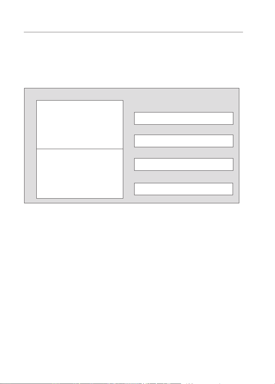
Device transfer
Device transfer
Dealer
Specify for all queries:
Appliance model
_____________________________________
Device no.:
______________________________________
Installer
Set to gas type:
______________________________________
Your device was checked by:
_____________________________________
4
Page 5

1 Introduction
1 Introduction
1.1 About this manual
> This installation manual is part of the device,
and contains information on its safe installation.
> Read this installation manual completely
before installing the device.
> This installation manual must be kept available
to installers at all times at the installation location.
> Keep this installation manual on hand throug-
hout the entire life of the device.
> This installation manual is to be passed on to
any subsequent operators of the device.
Target group The target group for this installation manual are
competent technicians who are familiar with the
process of installing and operating the device.
Illustrations All illustrations in this manual are examples only.
Deviations between these illustrations and the
device on site are possible.
This manual applies to the following devices:
> SelfCookingCenter® XS UV
> SelfCookingCenter® XS UV Plus
> CombiMaster® Plus XS UV
> CombiMaster® Plus XS UV Plus
Abbreviations used in this manual:
Product name Abbreviation used
SelfCookingCenter® XS UV SCC
CombiMaster® Plus CMP
UltraVent UV
We reserve the right to make technical changes in the interest of progress!
© 2017 RATIONAL Technical Services. All rights reserved. Forwarding product-speci-
c information to third parties is prohibited.
5
Page 6
1 Introduction
1.2 Warnings used
DANGER!
Directly hazardous situation that may result in
severe injury or death.
WARNING!
Possibly hazardous situation that could potentially result in serious injury or death.
CAUTION!
Possibly hazardous situation that could result
in minor injury.
CAUTION!
Fire hazard!
CAUTION!
Danger of burns!
CAUTION!
Corrosive substances!
DANGER!
High voltage.
Caution, danger to life
Non-compliance can result in severe injury or
death.
ATTENTION!
Non-compliance may result in material dama-
6
ge.
Page 7

1 Introduction
1.3 Warranty
Exceptions to the warranty include
> Damage to glass, light bulbs and seal materi-
als,
> Damage resulting from improper use, installa-
tion, maintenance, repair or descaling,
> Use of the device for purposes other than
those for which it is intended,
> Modifications or technical alterations to the
device not authorized by the manufacturer,
> Usage of non manufacturer-original service
components,
> Damage resulting from failure to observe the
instructions in this manual.
2 Safety instructions
Incorrect installation > Incorrect installation, service, maintenance or
cleaning of this device can result in damage,
injury or death, as can modifications to the
device. Read the installation manual carefully
prior to installation.
Device usage > The device may only be used for purposes of
cooking food in commercial kitchens. All other
uses are counter to its intended purpose, and
may be dangerous.
Operating personnel > This device must not be used by children or
by persons with reduced physical, sensory or
mental capabilities, or by persons with insufficient experience and/or knowledge, unless
such persons are under the supervision of
another person who takes responsibility for
their safety.
> To avoid accidents or damage to the device, it
is imperative that operating personnel receive
regular training and safety instructions.
7
Page 8

3 Installation instructions
3 Installation instructions
Standards > The mentioned standards are according to
German regulations.
> Local and country-specic standards and
regulations regarding the installation and operation of commercial cooking appliances must
be observed at all times.
> In all other countries, the corresponding
country-specic standards and regulations are
to be observed.
Liability / Warranty > Damage occurring as a result of non-compli-
ance with installation instructions is excluded
from the warranty.
> Installations and repairs not carried out by
authorized professionals or not using original
spare parts, and technical modications to
the machine which are not approved by the
manufacturer, void the manufacturer’s warranty and product liability.
Conformity > Device conformity is in reference to the ove-
rall unit at the time of delivery. The operator is
responsible for ensuring extended conformity
following any expansions/connection of additional functions.
Connection work > The necessary connections (water, electricity,
and gas) must only be set up by trained professionals in accordance with local regulations.
Prior to installation > Check the device for transport damage.
If you suspect the device has been damaged in
transit, contact your specialist dealer/freight
forwarder immediately!
Disposing of old appliances > When the device reaches the end of its ser-
vice life, it must not be taken to a municipal
collection point for trash or used electrical
appliances. We would be pleased to assist you
in disposing of the device.
8
Page 9

1 Introduction
Air lter maintenance: > The device automatically detects dirty air
filters. It will display a service prompt instructing you to replace the air filter.
> Never operate the device without the air filter.
When replacing the air filter, please note:
The user may replace the air filter. To replace the
air filter, carefully latch the new filter into the
correct position. Follow the instructions in the
Building Equipment and Appliances chapter of
the user’s manual.
Air filter part number: 40.04.771
9
Page 10
4 Device transportation
4 Device transportation
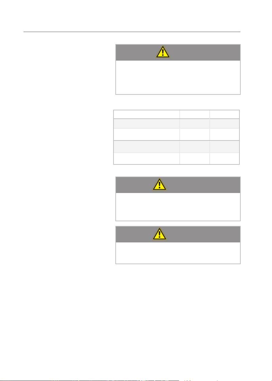
Weight (without packaging)
CAUTION!
Risk of injury!
Note device weights.
Use lifting aids.
Wear safety shoes.
kg lbs
SCC XS UV 97 214
SCC XS UV Plus 104 230
CMP XS UV 87 192
CMP XS UV Plus 94 207
ATTENTION!
Risk of damage to the device!
10
When transporting device, ensure that air filter
box and USB port remain undamaged.
ATTENTION!
Risk of damage to the unit!
Do not lift at the front panel of the UV!
Page 11
4 Device transportation
x
x
Transporting unit with pallet:
Note required door width:
880 mm [34 3/4)
Transporting unit without pallet:
Note required entrance width:
630 mm [24 3/4]
11
Page 12
5 Setting up the device
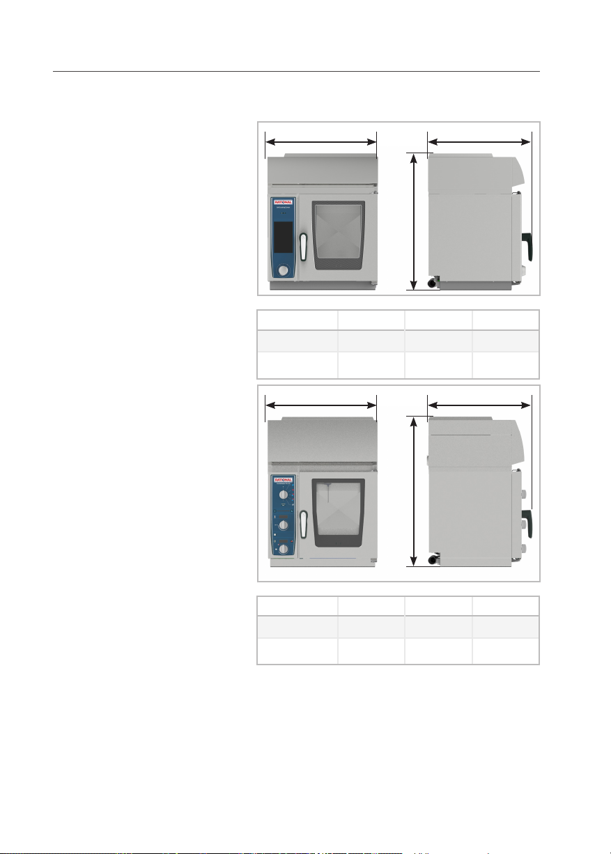
5 Setting up the device
5.1 Device dimensions
with UltraVent XS
x y
z
Width x Depth y Height z
[mm] 657 623 808
[Inch] 25 7/8 24 1/2 31 3/4
x y
with UltraVent XS Plus
12
z
Width x Depth y Height z
[mm] 657 623 897
[Inch] 25 7/8 24 1/2 35 3/8
Page 13

5 Setting up the device
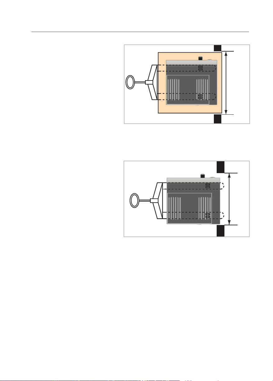
5.2 Minimum distances
ATTENTION!
Device overheating may cause material damage!
If the ambient temperature to the left of the
device becomes too high, it may trigger an
emergency shutdown of the device.
ATTENTION!
Device overheating may cause material damage!
Do not install fryers onto the back of the
device.
ATTENTION!
Frost may cause material damage!
Minimum distance to walls
Only install devices in frost-proof rooms.
x
y
x: 10 mm [1/2]
y: 10 mm [1/2]
13
x
Page 14

5 Setting up the device
500mm
/20"
min. 350 mm
Recommendation At least 500 mm away from left side of the
device so that service work can be performed.
Minimum distance to ceiling
450mm/
18“
Minimum distance to other devices Minimum 350 mm distance between left side of
the device and heat sources.
14
350mm/
14“
Page 15

5 Setting up the device
Other
ATTENTION!
Device malfunction!
Avoid vapor sources near the cooling air filter.
Moisture intake may result in device malfunctions.
15
Page 16

5 Setting up the device
5.3 Securing the device
For safety reasons, tabletop units should only be
placed atop a manufacturer-original oven stand
or base unit. Maximum working height for the
topmost rack is 1600 mm.
Unit size 60 These units do not have height-adjustable feet;
instead, they are set up directly on the installation surface.
The installation surface must be level, clean and
free of grease. Unevenness across the width of
the device must be no greater than 1 mm.
A sealant band is affixed to the underside of the
device to seal the installation site. This prevents
dirt from getting underneath the device. When
moving the device, take care not to damage this
seal.
Mounting onto an oven stand:
> Insert the two included neoprene blind rivet
nuts into the holes in the rear part of the
underbody.
> Place the unit onto the oven stand.
> Secure in place using the screws provided.
16
Page 17

6 Electrical connection
6 Electrical connection
DANGER!
Danger to life!
High voltage.
Observe local energy supply company regulations during installation!
WARNING!
Danger to life!
Connecting incorrectly may result in electric
shock!
Note color coding of wires!
Color coding of wires:
yellow/green = protective conductor,
blue = neutral conductor
brown, gray or black = phase L1, L2, L3
ATTENTION!
Improper connection can cause damage to the
6.1 General information
Only connect the device in accordance with the
Connect the device to a standard power supply
Observe VDE regulations and/or local energy
Connect the device to a Type B (RCD Type B)
17
unit (e.g., fan motor).
installation instructions and the information on
the rating label.
in accordance with the applicable regulations.
supply company regulations!
ground fault circuit interrupter.
Page 18

6 Electrical connection
CAUTION!
Improper installation can lead to personal injury or property damage!
Customer: provide accessible all-pole disconnect device with at least 3mm contact separa-
Remove the left side panel to access the connec-
Removing the left side wall > Remove the screws on the bottom of the side
> Pull the side panel down from the device.
> Remove the side panel.
tion.
tion port.
panel.
Each device should have its own protected
power supply line.
Use a fixed connection to connect each device to
the power supply.
3NAC 400V only Either a fixed connection or a plug connection
may be used to connect the device to the power
supply.
The units are equipped with power cables (without plugs).
The cables are around 2.5 m in length.
.Cable connection point The main fuse is behind the removable left side
panel inside the electrical compartment.
18
Page 19

6 Electrical connection
6.2 Power supply cable
ATTENTION!
In order to avoid hazards, the mains power
cable may only be replaced by the manufacturer, its customer service representative or similarly qualified personnel.
ATTENTION!
Non-functioning device !
Connect a supply cable of at least Type H07RN-F
Connect the cable according to the following
Tighten mains lead cleat.
and tighten the mains lead cleat.
diagram:
Gray connector terminals:
L1, L2, L3 (independent of rotary field).
Blue connector terminal:
Neutral conductor (neutral wire) (3NAC only).
Yellow-green connector terminals: Protective
conductors.
19
Page 20

6 Electrical connection
6.3 Equipotential bonding
A connection site for optional equipotential bon-
ding is located on the bottom or the back of the
device.
6.4 Connection values
SCC, CM_P
Power [kW] /
Current consumption [A]
3 AC 200V 5,3 / 15,4 16
3 AC 230V 5,70 / 14,5 16
3 NAC 400V 5,7 / 8,5 10
3 NAC 415V 6,2 / 8,7 10
1 NAC 230V 5,3/22,9 25
1 NAC 240V 5,7/24 25
2 AC 230V 5,3/22,9 25
2 AC 240V 5,7 / 24 25
Fuse [A]
Maximum permissible tolerance for input voltage (see type label for input voltage) is
within the range of -15% to + 10%.
20
Page 21

7 Water connection
7 Water connection
The device complies with all relevant regulations
(SVGW, KIWA, WRAS).
7.1 Prerequisites
> The user must supply each device with its
own water tap.
> Rinse the water supply line before connecting
the device to water!
> Water pressure 1.5 - 6bar, 3bar recommen-
ded.
> Flow rates required for each unit:
1,8 g/min
Connect the device to drinking water-quality
water.
Connect a flexible drinking-water connection
hose in accordance with EN 61770 or EN 13618
or of similar quality. Take any necessary safety
precautions with the water tap, such as backflow
preventers or CA system separators.
The water connection hose must comply with
country-specific hygiene standards for drinking
water hoses.
Water connection hoses complying with EN
61770 are available through Rational using part
number 2067.0709.
The materials used in this connection hose meet
KTW, DVGW W270, WRAS and FDA requirements.
Use only new hoses as water connections. Do
not re-use old hoses.
ATTENTION!
Non-functioning device!
Ensure that the minimum water conductivity
value of 50µS/cm (Micro Siemens) is maintai-
21
ned.
Page 22

7 Water connection
Unit CMP XS due to descaling of the steam generator:
> Drinking water protection for substance class
3 pursuant to EN 1717, such as a CA system
separator pursuant to EN 14367, must be
installed in the feed line on the tap at the drinking water network connection point.
> The CA system separator is supplied for NL
and CH, and are available through RATIONAL
using part number 50.01.820 for other European countries.
Unit SCC XS meet the requirements for drinking water pro-
tection pursuant to EN1717 in as-delivered condition.
UK only: WRAS approval IRN R160
To be carried out by the installer:
An approved double check valve or some other
no less effective backflow prevention device shall
be fitted at the point of connection directly to
the water tap.
7.2 Device water connection
1
Water connection legend 1 = 3/4” common water supply line.
(cold water up to 30°C [86°F])
Note: The manufacturer recommends preventative
inspection be conducted around six months after
device commissioning to ascertain the degree of
limescale buildup in the steam generator, especially for CMP units.
This inspection should be performed by a trained
technician.
22
Page 23

7 Water connection
7.3 Water treatment
> The water connection must not use treated
water with hardness below 6°e, as such water
is aggressive and corrosive, and can shorten
the lifespan of the device.
> Connecting the SCC to water with hardness
below 8,75°e:
When the self-test begins, the system will
prompt the user to indicate the hardness of
the water the device is connected to. Select
“Water hardness below 8,75°e.
> Observe all country-specific regulations
regarding water and sewer connections, especially those regarding installation of water
intake points.
In most cases, water connections do not require
additional filters or water treatment.
Filtration and/or water treatment (A, B, C, D)
may be necessary if water conditions are critical.
Contact the local water supply company to
inquire about water chloride levels (Cl–), chlorine
levels (Cl2) and hardness.
7.4 Selectingwaterlters
A) Fine filters We recommend fine filters with fineness of 5 -
15µm for filtering water contaminated with sand,
iron particles or suspended matter.
B) Active carbon filters If water contains high levels of Cl2 (over 0.2mg/l,
corresponds to 0.2ppm) (information provided
by water supply company), an upstream active
carbon filter must be installed.
C) Reverse osmosis system Due to corrosion risks, a reverse osmosis system
must be used if and only if chloride (Cl–) concentrations are above 80mg/l (corresponds to
80ppm, information provided by water supply
company).
Note: Ensure that the minimum conductivity
value of 50µS/cm (Micro Siemens) is being
maintained.
23
Page 24

7 Water connection
D) Water softening:
SCC: When used properly, these devices remove lime
from water completely independently, so upscale
water softening is not necessary.
CMP/CM: Recommended for treating water if severe calci-
fication occurs (without chloride contamination).
Systems: Weak acid decarbonization (H+ ion
exchange). Sodium ion exchangers (as are commonly found in dishwashers) are not recommended.
Phosphate metering is also not recommended
due to its negative effects on the water system.
Important for soft water connections:
Filter size sufficient for:
7 l/min
Important for filter connections: Water hose with minimum ø 1/2”.
Filter connection ø 3/4”.
When using a combination of filters, ensure filter
sequence of A-B-C or A-B-D in direction of flow.
24
Page 25

8 Wastewater connection
8 Wastewater connection
ATTENTION!
Use only steam temperature-resistant pipes
> Device complies with all relevant regulations
> Connection set for device drain
for wastewater drainage. Do not use hoses.
(SVGW, KIWA, WRAS).
DN 40/50 Part number: 8720.1031
> Welding a drain pipe onto the device drain is
not permitted (could result in damage to the
device).
> Use DN 50 pipe (DN 40 for size 60 units) with
a constant gradient (at least 5% or 3°); do not
reduce pipe diameter.
> Observe drain dimensioning requirements:
steam generator short-term pump-off rate =
0.7l/s
> Average wastewater temperature: 65°C
[149°F]
> Applicable standard: DIN 1986, T1
> If floor drain has no odor seal, make sure a
2cm [1” ] free outflow zone is in place.
> We recommend integrating a siphon into the
wastewater connection in order to optimize
energy consumption.
> Unit sizes 60 through 12 may have both a
wall drain and a floor drain
> Each device must have its own wastewater
connection (including Combi-Duos).
25
Page 26

8 Wastewater connection
250-300 mm
(10 - 12 “)
max. 1 m (3 ft.)
Ø 40 mm (1¾”)
min. 3°/5%
min. 3°/5%
Ø 40 mm (1½”)
26
Page 27

9 Ventilation, technical data, heat dissipation
9 Ventilation, technical data, heat dissipation
On-site ventilation: When installing an exhaust hood, observe the
following:
> VDI Directive 2052 and local construction
authority regulations on exhaust hoods.
The exhaust hood should protrude 300-500
mm over the front of the device.
> Install the device underneath an exhaust hood
if using a VarioSmoker.
> Install a grease filter into the protruding part
of the exhaust hood.
Technical data Noise emissions value: <70dBA
Water jet protection: IPX5
Thermal load [kJ/h]:
SCC CMP
latent: 1.020 1110
sensible: 1.350 1420
We reserve the right to make technical developments / modifications.
27
Page 28

10 Initial start-up
1600 mm (63”)
10 Initial start-up
WARNING!
Scalding hazard!
To avoid scalding, when working with liquids
or foods that become liquid when heated to
higher temperatures, only use containers that
The “Max. rack height for containers with liquid”
are easy to monitor. (DIN: IEC 60335-2-42).
safety decal is included in the starter kit. After
installing the device, attach the decal at a height
of 1600 mm (see example)
28
ATTENTION!
Risk of fire!
Remove packaging and transportation materials, starter kit, grids and containers from the
cooking chamber.
Page 29

10 Initial start-up
Self test When first commissioning a new device, start a
one-time self-test. This test serves to adjust the
device to its specific ambient conditions.
It runs automatically, and takes 45 minutes; if an
UltraVent is in use, the test will take around 20
minutes longer.
> To perform the self-test, check the hook lad-
ders and the air baffle to ensure they are seated correctly.
> The device must be connected to water,
wastewater, and electricity as per installation
instructions; gas devices must also be connected to gas supply and exhaust lines.
> The left side panel must be closed.
> Insert a flat GN container into the middle of
the hook ladders, with the opening facing the
bottom.
> Do not open the cooking chamber door duri-
ng the self-test.
29
Page 30

10 Initial start-up
SCC
CMP
30
Page 31

11 Maintenance:
11 Maintenance:
NOTIZ
Risk of fire!
Not cleaning the UV can result in the risk of
Before maintenance: > Isolate unit from mains.
> Remove 2 screws at UV top and remove top
fire.
WARNING
Danger of cutting!
The UV Plus ceiling can be sharp-edged.
Wearing safety gloves.
cover.
> Depending on the degree of soiling, unscrew
the UV Plus covers and clean them in the
dishwasher.
> Wash inner chamber of UV with hand shower.
> After cleaning fix the UV top cover back.
31
Page 32

11 Maintenance:
ONLY UV Plus: > Pull out the pre-filter
> Clean the pre-filter in the dishwasher
Exchange of HEPA filter The yellow LED indicates when the HEPA filter
should be replaced.
> Isolate unit from mains.
> Remove the front panel.
> Loose marked screws, pull out the filter unit.
32
Page 33

11 Maintenance:
> Change HEPA filter.
33
Page 34

12 Service parts
12 Service parts
12.1 UltraVent
Art.N.° Description
42.00.284 PCB UV
40.05.843 Bus cable WA44
40.05.963 Main contactor K1/K2
40.04.151 Capacitor 3,5 µF
40.05.413 Capacitor 8 µF
60.72.439 Motor UV WA44 (M1) 200-240 V
60.74.459 Mounting frame
60.73.956 Gasket
60.73.957 Cover plate for right hinged units
60.73.958 Cover plate for le hinged units
60.73.960 Front panel
34
Page 35

12 Service parts
12.2 UltraVent Plus
Art.N.° Description
42.00.284 PCB UV
40.05.843 Bus cable WA44
40.05.963 Main contactor K1/K2
40.04.151 Capacitor 3,5 µF
40.04.152 Capacitor 10 µF
60.72.439 Motor UV WA44 (M1) 200-240 V
60.74.459 Mounting frame
60.73.956 Gasket
60.73.957 Cover plate for right hinged units
60.73.958 Cover plate for le hinged units
60.74.464 Front panel
60.74.403 HEPA filter
60.74.409 Pre-filter
3017.1014 Differential pressure switch
40.05.972 LED yellow
3019.0117 Fuse 5x20 2,5AT
35
Page 36

13 Options
13 Options
Wall mount The device can be attached to the wall using a wall
mount.
ATTENTION!
Be sure to follow the corresponding modification instructions when performing wall instal-
Article number: 60.30.968
Interfaces
lations.
SCC come with an Ethernet interface as part of their
standard equipment. An CAT-5 Ethernet cable
must be used to connect to a network.
Connection location: on the rear of the unit
A detailed description on connecting to a network
is provided in the user manual.
CMP can optionally be ordered or retrofitted with
Ethernet interfaces.
Part number for add-on kit:
87.01.419
.
36
Page 37

14 Conversion tables
14 Conversion tables
°dH °f °e ppm mmol/l gr/
gal(US)
1 °dH 1 1.79 1.25 17.9 0.1783 1.044 0.357
1 °f 0.56 1 0.70 10.0 0.1 0.584 0.2
1 °e 0.8 1.43 1 14.32 0.14 0.84 0.286
1 ppm 0.056 0.1 0.07 1 0.01 0.0584 0.02
1 mmol/l 5.6 0.001 0.0007 100 1 0.00058 2
1 gr/gal (US) 0.96 1.71 1.20 17.1 0.171 1 0.342
1 mval/kg 2.8 5.0 3.5 50 0.5 2.922 1
CaO[mg/l] CaCO3 [mg/l] Ca
1 °dH (Germany) 10.00 17.86 7.14
1 °f (France) 5.60 10.0 4.00
1 °e (GB) 8.01 14.3 5.72
1 ppm (USA) 0.56 1.0 0.40
1 mmol/l (chem. cons.) 56.00 100.0 39.98
1 gr/gal (USA) 9.60 / 64.8 17.11 6.85
1 mval/kg (milliequivalent) 28.00 50.0 19.99
kPa mbar psi inch/wc
0.1 1 0.0147 0.4014
0.2 2 0.0294 0.8028
0.3 3 0.0441 1.2042
0.4 4 0.0588 1.6056
0.5 5 0.0735 2.0070
0.6 6 0.0882 2.4084
0.7 7 0.1029 2.8098
0.8 8 0.1176 3.2112
0.9 9 0.1323 3.6126
1 10 0.147 4.0140
1.2 12 0.1764 4.8168
1.4 14 0.2058 5.6196
1.6 16 0.2352 6.4224
1.8 18 0.2646 7.2252
2 20 0.294 8.0280
2+
[mg/l]
mval/kg
37
Page 38

14 Conversion tables
2.5 25 0.3675 10.0350
3 30 0.441 12.0420
3.5 35 0.5145 14.0490
4 40 0.588 16.0560
4.5 45 0.6615 18.0630
5 50 0.735 20.0700
5.5 55 0.8085 22.0770
6 60 0.882 24.0840
6.5 65 0.9555 26.0910
7 70 1.029 28.0980
7.5 75 1.1025 30.1050
8 80 1.176 32.1120
8.5 85 1.2495 34.1190
9 90 1.323 36.1260
9.5 95 1.3965 38.1330
10 100 1.47 40.1400
20 200 2.94 80.2800
30 300 4.41 120.4200
40 400 5.88 160.5600
50 500 7.35 200.7000
100 1000 14.7 401.4000
38
Page 39

15 Declaration of conformity
15 Declaration of conformity
39
Page 40

80.02.467 · V-13.2 · 04/2018 · RTS · Dja en
 Loading...