


Selfcookingcenter
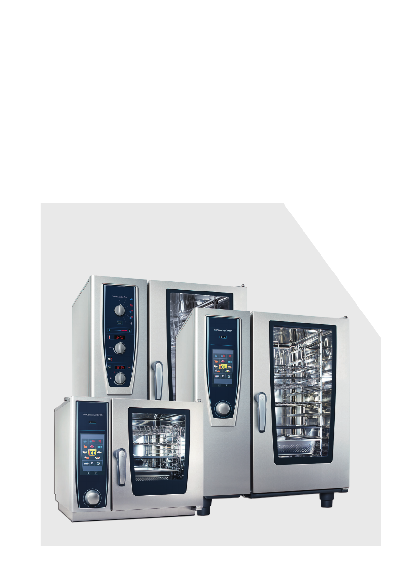
SelfCookingCenter®
CombiMaster® Plus
CombiMaster®
Original Installation Manual

Contents
Device transfer 4
1 Introduction 5
1.1 About this manual 5
1.2 Warnings used 7
1.3 Warranty 8
2 Safety instructions 9
3 Installation instructions 11
4 Device transportation 13
5 Setting up the device 16
5.1 Device dimensions 16
5.2 Minimum distances 18
5.3 Securing the device 20
5.3.1 Tabletop units 20
5.3.2 Floor units 26
6 Electrical connection 30
6.1 General information 30
6.2 Electrical devices 32
6.3 Gas devices 32
6.4 Power supply cable 33
6.5 Equipotential bonding 34
6.6 Connection values 35
7 Water connection 38
7.1 Prerequisites 38
7.3 Water treatment 41
7.4 Selecting water filters 41
8 Gas connection 43
2

9 Exhaust gas connection 47
9.1 Type A3 48
9.2 Type B13 50
9.3 Type B13BS 51
9.4 Flow guards for B13 and B13BS 51
9.5 Maintenance 52
10 Wastewater connection 53
11 Ventilation, technical data, heat dissipation 56
12 Initial start-up 58
13 Options 61
14 Conversion tables 69
3

Device transfer
Device transfer
Dealer
Specify for all queries:
Appliance model
_____________________________________
Device no.:
______________________________________
Installer
Set to gas type:
______________________________________
Your device was checked by:
_____________________________________
4

1 Introduction
1 Introduction
1.1 About this manual
> This installation manual is part of the device,
and contains information on its safe installation.
> Read this installation manual completely
before installing the device.
> This installation manual must be kept available
to installers at all times at the installation location.
> Keep this installation manual on hand
throughout the entire life of the device.
> This installation manual is to be passed on to
any subsequent operators of the device.
Target group The target group for this installation manual are
competent technicians who are familiar with the
process of installing and operating the device.
Illustrations All illustrations in this manual are examples only.
Deviations between these illustrations and the
device on site are possible.
We reserve the right to make technical changes in the interest of progress!
© 2016 Rational Technical Services. All rights reserved. Forwarding product-specic
information to third parties is prohibited.
5
1 Introduction
This manual applies to the following devices:
> all SelfCookingCenter® WE units
> SelfCookingCenter® XS
> all CombiMaster® Plus units
> CombiMaster
Abbreviations used in this manual:
Product name Abbreviation used
SelfCookingCenter® WE SCC
SelfCookingCenter® XS SCC
CombiMaster® Plus CMP
CombiMaster
Appliance size Abbreviation used
6 x 2/3 GN 60
6 x 1/1 GN 61
6 x 2/1 GN 62
10 x 1/1 GN 11
10 x 2/1 GN 12
20 x 1/1 GN 21
20 x 2/1 GN 22
®
®
CM
Unit sizes 60, 61, 62, 11, and 12 are referred to collectively as tabletop units.
Unit sizes 21 and 22 are referred to collectively as floor units.
Device overview:
60 61 62 11 12 21 22
SCC Electro
SCC Gas
CMP Electro
CMP Gas
CM Electro
x x x x x x x
x x x x x x
x x x x x x x
x x x x x x
x x
6
1 Introduction
1.2 Warnings used
DANGER!
Directly hazardous situation that may result in
severe injury or death.
WARNING!
Possibly hazardous situation that could potentially result in serious injury or death.
CAUTION!
Possibly hazardous situation that could result
in minor injury.
CAUTION!
Fire hazard!
CAUTION!
Danger of burns!
CAUTION!
Corrosive substances!
DANGER!
High voltage.
Caution, danger to life
Non-compliance can result in severe injury or
death.
ATTENTION!
Non-compliance may result in material dam-
7
age.

1 Introduction
1.3 Warranty
Exceptions to the warranty include
> Damage to glass, light bulbs and seal materi-
als,
> Damage resulting from improper use, installa-
tion, maintenance, repair or descaling,
> Use of the device for purposes other than
those for which it is intended,
> Modifications or technical alterations to the
device not authorized by the manufacturer,
> Usage of non manufacturer-original service
components,
> Damage resulting from failure to observe the
instructions in this manual.
8
2 Safety instructions
2 Safety instructions
Incorrect installation > Incorrect installation, service, maintenance or
cleaning of this device can result in damage,
injury or death, as can modifications to the
device. Read the installation manual carefully
prior to installation.
Device usage > The device may only be used for purposes of
cooking food in commercial kitchens. All other
uses are counter to its intended purpose, and
may be dangerous.
Gas appliances
WARNING!
Combustion gases!
When installing under an exhaust hood: Switch
the exhaust hood on when the device is in
operation.
WARNING!
Fire hazard!
When connecting to a chimney: Clean the ven-
tilation pipe regularly in accordance with coun-
> Do not place anything atop the device’s
> Make sure that the area around the com-
> Only operate in wind-free areas.
9
try-specific regulations (contact installer).
exhaust pipes.
bustion air extractor is not blocked by any
objects.
2 Safety instructions
Operating personnel > This device must not be used by children or
by persons with reduced physical, sensory or
mental capabilities, or by persons with insufficient experience and/or knowledge, unless
such persons are under the supervision of
another person who takes responsibility for
their safety.
> To avoid accidents or damage to the device, it
is imperative that operating personnel receive
regular training and safety instructions.
Explosion hazard
WARNING!
Explosion hazard
If you smell gas:
> Shut off gas supply immediately,
> Do not touch any electrical switching ele-
ments,
> Ventilate the room well,
> Avoid any open flames or sparks,
10
> Use an external telephone to inform the gas
provider immediately. If the gas provider
cannot be reached, call the local fire depart-
ment.

3 Installation instructions
3 Installation instructions
Standards > The mentioned standards are according to
German regulations.
> Local and country-specic standards and reg-
ulations regarding the installation and operation of commercial cooking appliances must
be observed at all times.
> In all other countries, the corresponding
country-specic standards and regulations
are to be observed.
Liability / Warranty > Damage occurring as a result of non-compli-
ance with installation instructions is excluded
from the warranty.
> Installations and repairs not carried out by
authorized professionals or not using original
spare parts, and technical modications to the
machine which are not approved by the manufacturer, void the manufacturer’s warranty
and product liability.
Conformity > Device conformity is in reference to the over-
all unit at the time of delivery. The operator is
responsible for ensuring extended conformity
following any expansions/connection of
additional functions.
Connection work> The necessary connections (water, electricity,
and gas) must only be set up by trained professionals in accordance with local regulations.
Prior to installation > Check the device for transport damage.
If you suspect the device has been damaged
in transit, contact your specialist dealer/
freight forwarder immediately!
Disposing of old appliances > When the device reaches the end of its ser-
vice life, it must not be taken to a municipal
collection point for trash or used electrical
appliances. We would be pleased to assist
you in disposing of the device.
11
3 Installation instructions
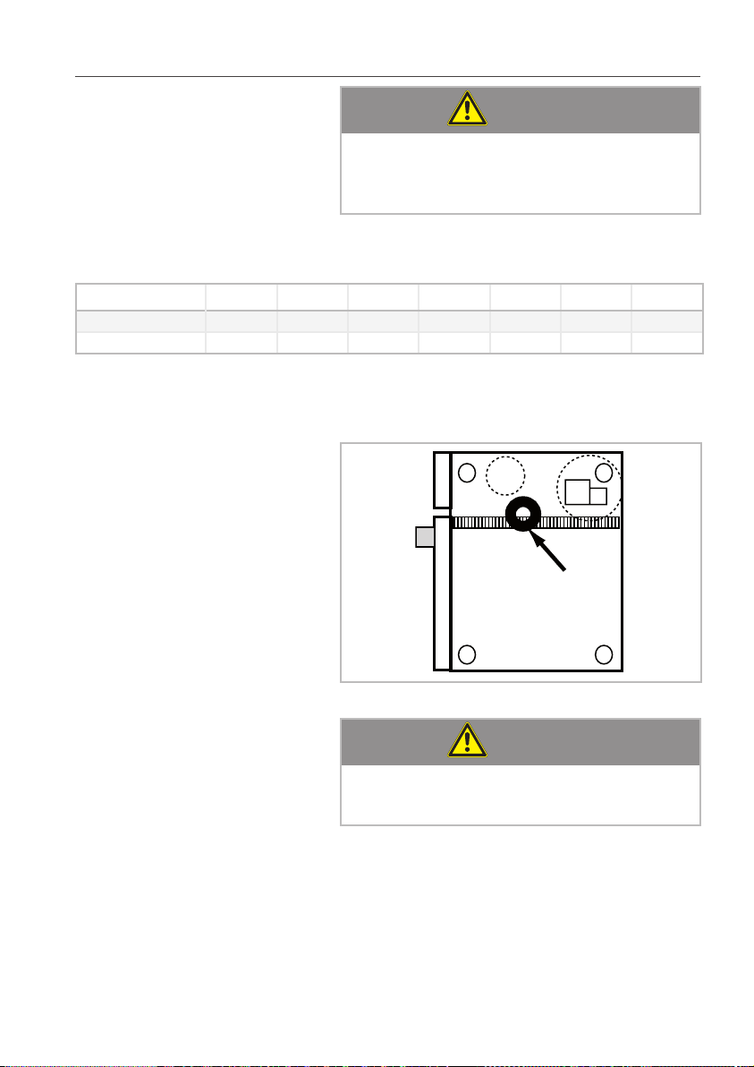
Air lter maintenance: > The device automatically detects dirty air fil-
ters. It will display a service prompt instruct-
ing you to replace the air filter.
> Never operate the device without the air filter.
When replacing the air filter, please note:
Tabletop units The user may replace the air filter. To replace the
air filter, carefully latch the new filter into the
correct position. Follow the instructions in the
Building Equipment and Appliances chapter of
the user’s manual.
Unit size 60 Air filter part number: 40.04.771
Unit sizes 61, 62, 11 and 12 Air filter part number: 40.02.684
Floor units Air lters on these units must only be replaced by
authorized service partners.
ATTENTION!
Water jet protection and reach-through protection on floor units are only guaranteed if air
filter and cover are correctly installed.
12
4 Device transportation
4 Device transportation
CAUTION!
Risk of injury!
Device may tip.
When transporting: Secure the device against
Weight (without packaging)
60 61 62 11 12 21 22
SCC Electro [kg] 72 111 145 136 189 266 343
SCC Electro [lb] 159 245 320 300 417 586 756
SCC Gas [kg] 130 173 159 205 294 381
SCC Gas [lb] 287 381 351 452 648 840
CMP Electro [kg] 62 103 147 132 182 254 334
CMP Electro [lb] 137 227 324 291 401 560 736
CMP Gas [kg] 114 160 143 196 284 354
CMP Gas [lb] 251 353 315 432 626 780
CM Electro [kg] 99 128
CM Electro [lb] 218 282
tipping.
CAUTION!
Risk of injury!
Note device weights.
Use lifting aids.
Wear safety shoes.
Unit size 60
ATTENTION!
Risk of damage to the device!
When transporting device, ensure that air filter
13
box and USB port remain undamaged.
4 Device transportation
x
x
Transporting unit with pallet:
Note required door width:
Appliance size 60 61 62 11 12 21 22
x [mm] 880 920 1120 920 1120 950 1150
x [Inch] 34 3/4 36 1/4 44 1/8 36 1/4 44 1/8 37 1/2 45 1/4
Transporting unit without pallet:
ATTENTION!
Risk of damage to the device!
Only floor units may be transported without a
palette using hand lifts.
Lay wooden beams underneath in gray area.
14
4 Device transportation
ATTENTION!
Risk of damage to the device!
Tabletop units not secured with a palette may
Note required entrance width:
Appliance size 60 61 62 11 12 21 22
x [mm] 630 845 1045 845 1045 925 1145
x [Inch] 24 6/8 33 1/4 41 1/8 33 1/4 41 1/8 36 3/8 45 1/8
Center of mass Keep the device’s center of mass in mind to pre-
only be transported using carrying straps.
vent it from tipping over.
ATTENTION!
Risk of damage to the device!
15
Note height of entrances.
5 Setting up the device
xy
xy
xy
5 Setting up the device
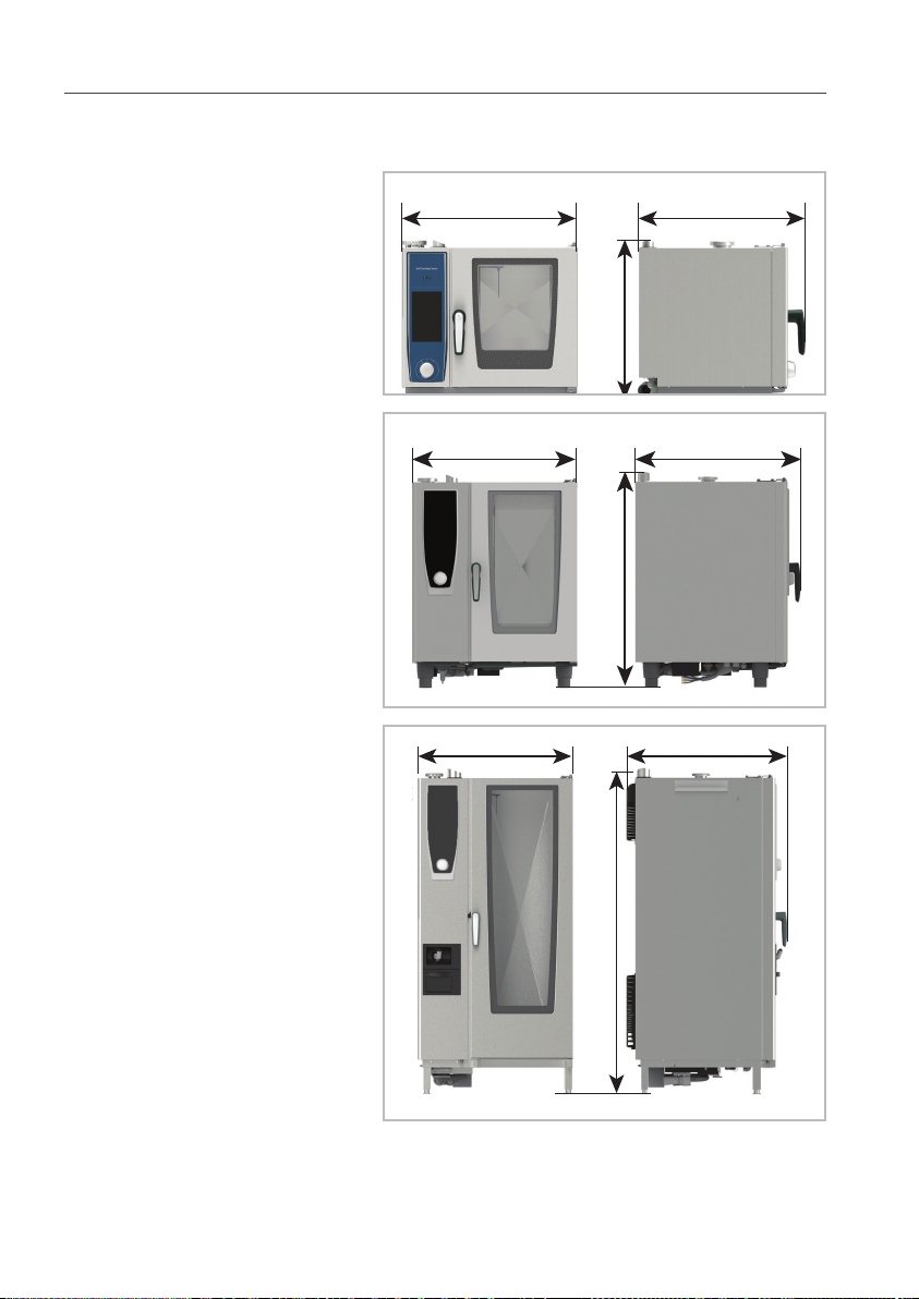
5.1 Device dimensions
z
z
16
z
5 Setting up the device
Width x 60 61 62 11 12 21 22
SCC, CMP, CM [mm] 657 847 1069 847 1069 879 1084
SCC, CMP, CM [Inch] 25 7/8 33 3/8 42 1/8 33 3/8 42 1/8 34 5/8 42 5/8
Depth y 60 61 62 11 12 21 22
SCC, CMP, CM [mm] 623 843 1043 843 1043 909 1114
SCC, CMP, CM [Inch] 24 1/2 33 1/4 41 1/8 33 1/4 41 1/8 35 3/4 43 7/8
Height z 60 61 62 11 12 21 22
SCC, CMP, CM el [mm] 598 832 832 1092 1092 1842 1842
SCC, CMP, CM el [Inch] 23 1/2 32 3/4 32 3/4 43 43 72 1/2 72 1/2
SCC, CMP gas [mm] 832 832 1092 1092 1842 1855
SCC, CMP gas [Inch] 32 3/4 32 3/4 43 43 72 1/2 73
17
5 Setting up the device
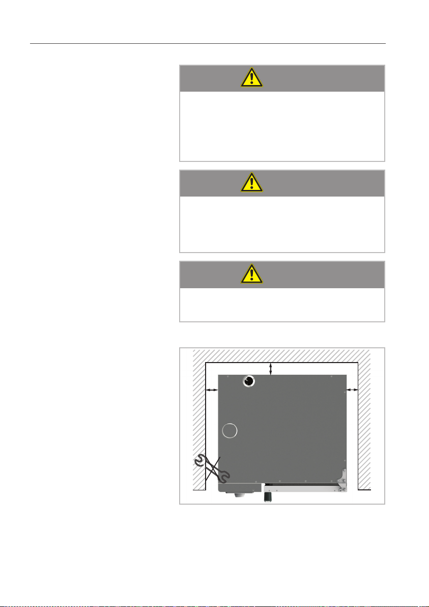
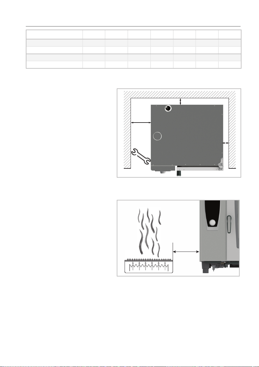
5.2 Minimum distances
ATTENTION!
Device overheating may cause material damage!
If the ambient temperature to the left of the
device becomes too high, it may trigger an
emergency shutdown of the device.
ATTENTION!
Device overheating may cause material damage!
Do not install fryers onto the back of the
device.
ATTENTION!
Frost may cause material damage!
Minimum distance to walls
18
Only install devices in frost-proof rooms.
x
y
x
5 Setting up the device
500 mm
/20"
350 mm/
14”
Appliance size 60 61 62 11 12 21 22
x [mm] 10 50 50 50 50 50 50
x [Inch] 1/2 2 2 2 2 2 2
y [mm] 10 50 50 50 50 500 500
y [Inch] 1/2 2 2 2 2 20 20
Recommendation At least 500 mm away from left side of the
device so that service work can be performed.
Minimum distance to other devices Minimum 350 mm distance between left side of
the device and heat sources.
Heat shield If it is not possible to keep the left side (or right,
on 61 and 11) of the device a sufficient distance
away from heat sources, a heat shield can reduce
thermal loads.
19
5 Setting up the device
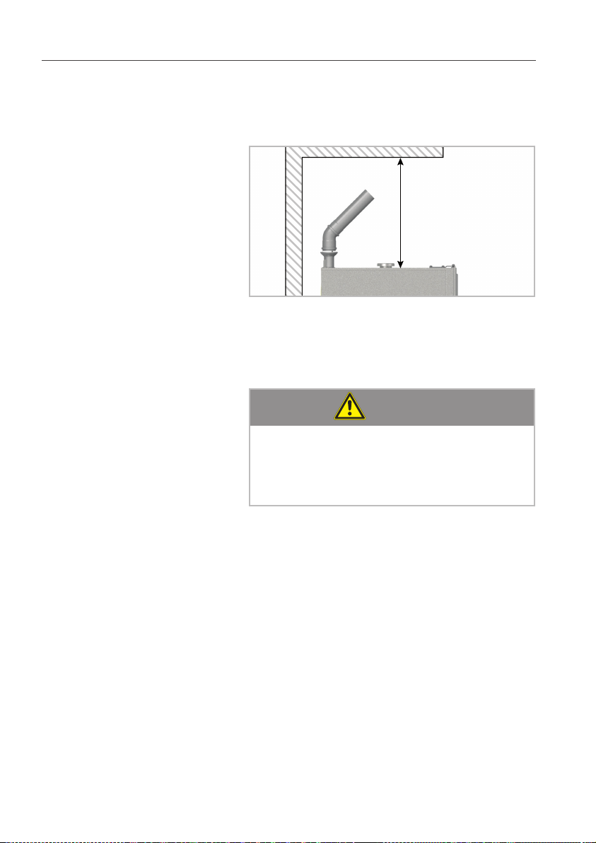
Minimum distance to ceiling If steam from the ventilation pipe cannot be
directed into an exhaust hood or a ventilating
ceiling, there must be at least 500mm clearance
space above the device.
min. 500 mm
Condensation breaker This clearance space is sufficient to install a
condensation breaker so that exhaust air can be
directed into non-critical areas.
Other
ATTENTION!
Device malfunction!
Avoid vapor sources near the cooling air filter.
Moisture intake may result in device malfunctions.
5.3 Securing the device
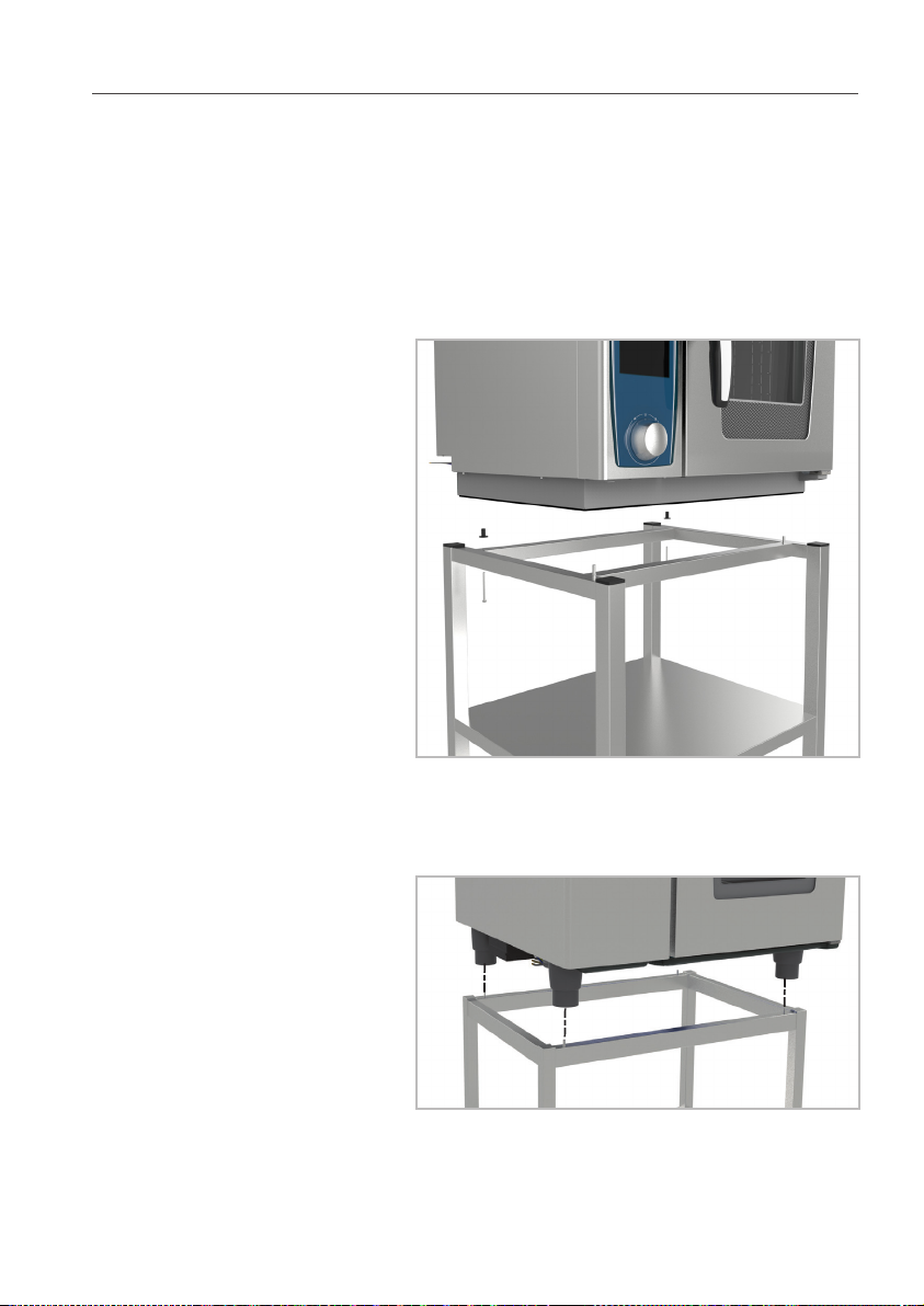
5.3.1 Tabletop units
For safety reasons, tabletop units should only be
placed atop a manufacturer-original oven stand
or base unit. Maximum working height for the
topmost rack is 1600 mm.
Unit size 60 These units do not have height-adjustable feet;
instead, they are set up directly on the installa-
tion surface.
The installation surface must be level, clean and
free of grease. Unevenness across the width of
the device must be no greater than 1 mm.
A sealant band is affixed to the underside of the
device to seal the installation site. This prevents
20
5 Setting up the device
dirt from getting underneath the device. When
moving the device, take care not to damage this
seal.
Mounting onto an oven stand:
Insert the two included neoprene blind rivet nuts
into the holes in the rear part of the underbody.
Place the device onto the oven stand.
Secure in place using the screws provided.
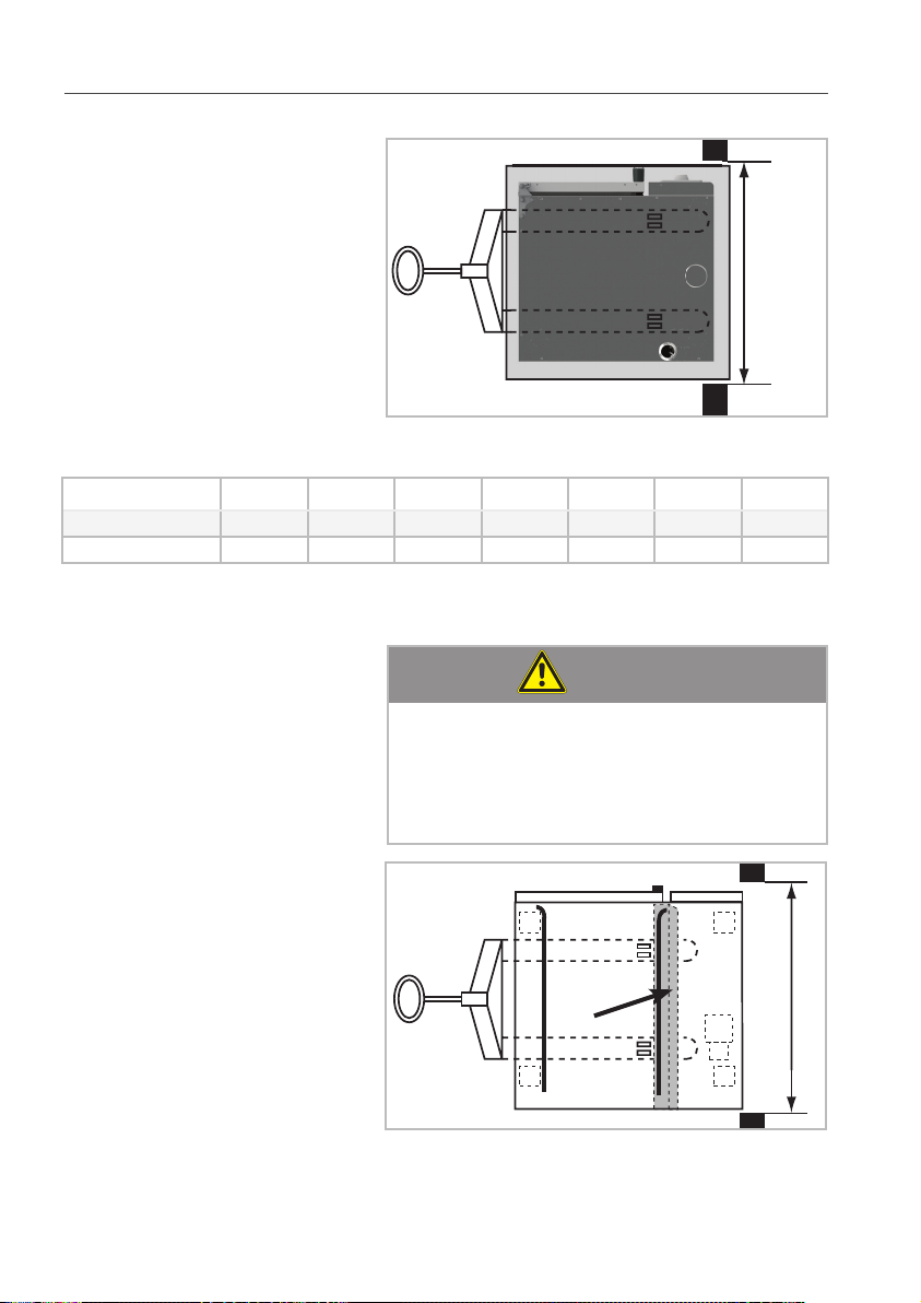
Unit sizes 61, 62, 11, 12 > Place the unit onto the stand. Lock the feet of
the unit in place using the locating pins on the
stand.
21
5 Setting up the device
+/- 10 mm
> Level the device
Gas appliances:
WARNING!
Risk of damage / injury!
Secure the gas device against slipping.
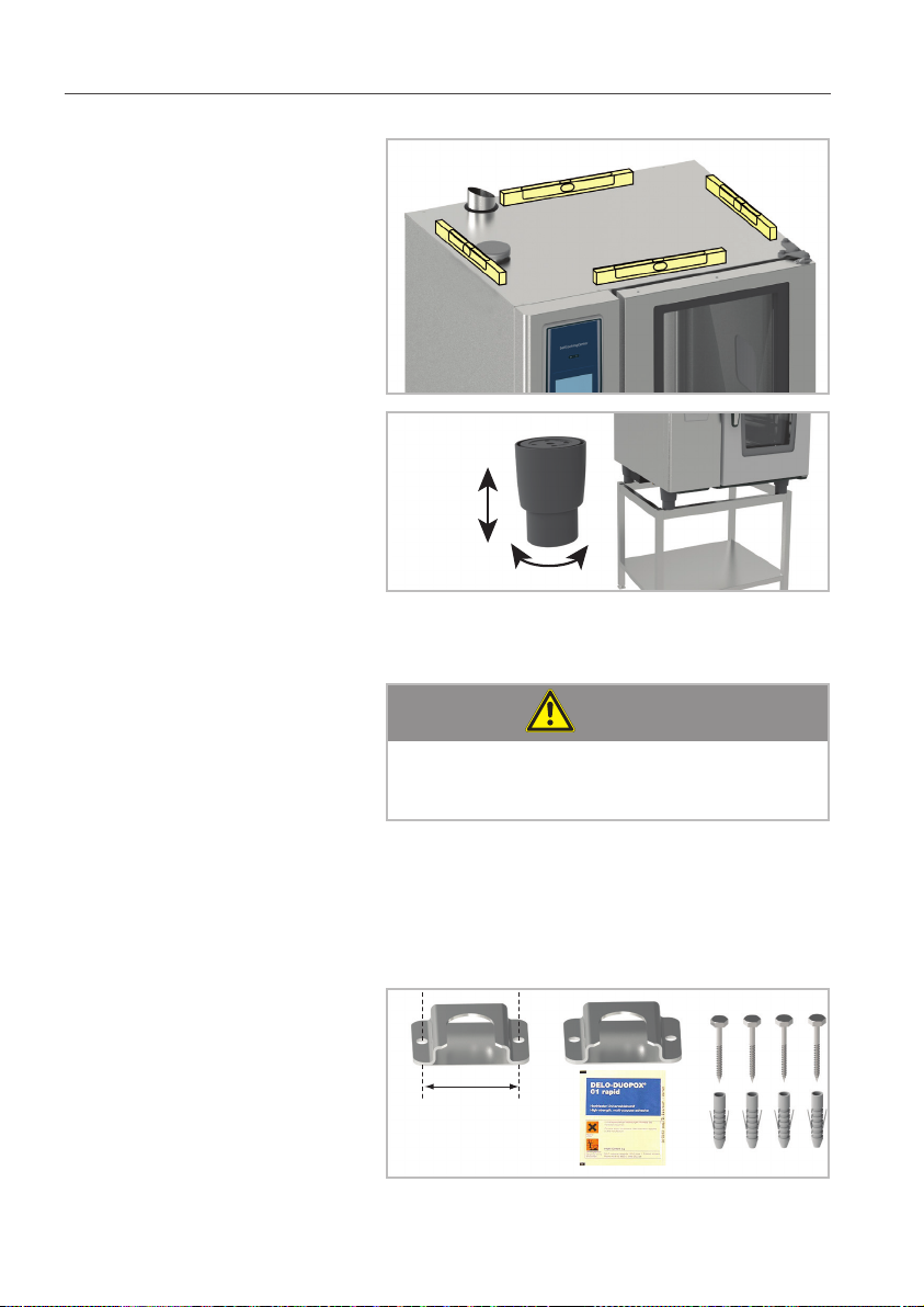
Installing onto an original oven stand:
> use the mounting kit (Part number
8700.0317) to attach the stand to the floor,
either with screws and dowels or with the
special adhesive provided.
64,5 mm
2 5/8"
22
 Loading...