

Ransburg Vector AA90 79580, Vector AA90 79581 Service Manual

SERVICE MANUAL
AH-07-01.8AH-07-01.8
AH-07-01.8
AH-07-01.8AH-07-01.8
(Replaces AH-07-01.7)
June 2010
VECTVECT
VECT
VECTVECT
OR AA90 APPLICAOR AA90 APPLICA
OR AA90 APPLICA
OR AA90 APPLICAOR AA90 APPLICA
TT
ORSORS
T
ORS
TT
ORSORS
MODELS:MODELS:
MODELS:
MODELS:MODELS:
79580 VECTOR CASCADE79580 VECTOR CASCADE
79580 VECTOR CASCADE
79580 VECTOR CASCADE79580 VECTOR CASCADE
79581 VECTOR CLASSIC79581 VECTOR CLASSIC
79581 VECTOR CLASSIC
79581 VECTOR CLASSIC79581 VECTOR CLASSIC
IMPORIMPOR
IMPOR
IMPORIMPOR
carefully read SAFETY PRECAUTIONS,carefully read SAFETY PRECAUTIONS,
carefully read SAFETY PRECAUTIONS,
carefully read SAFETY PRECAUTIONS,carefully read SAFETY PRECAUTIONS,
starting on page 1, and all instructions in thisstarting on page 1, and all instructions in this
starting on page 1, and all instructions in this
starting on page 1, and all instructions in thisstarting on page 1, and all instructions in this
manual. Keep this Service Manual for futuremanual. Keep this Service Manual for future
manual. Keep this Service Manual for future
manual. Keep this Service Manual for futuremanual. Keep this Service Manual for future
reference.reference.
reference.
reference.reference.
TT
ANTANT
T
ANT
TT
ANTANT
: Before using this equipment,: Before using this equipment,
: Before using this equipment,
: Before using this equipment,: Before using this equipment,
Service Manual Price:Service Manual Price:
Service Manual Price: €
Service Manual Price:Service Manual Price:
40.00 (Euro)40.00 (Euro)
40.00 (Euro)
40.00 (Euro)40.00 (Euro)
$50.00 (U.S.)$50.00 (U.S.)
$50.00 (U.S.)
$50.00 (U.S.)$50.00 (U.S.)

NOTE:NOTE:
NOTE: This manual has been changed from revision
NOTE:NOTE:
Reasons for this change are noted under “Manual Change Summary” inside the back
cover of this manual.
AH-07-01.7 AH-07-01.7
AH-07-01.7 to revision
AH-07-01.7 AH-07-01.7
AH-07-01.8. AH-07-01.8.
AH-07-01.8.
AH-07-01.8. AH-07-01.8.
AH-07-01.8

CONTENTSCONTENTS
CONTENTS
CONTENTSCONTENTS
SAFETY:SAFETY:
SAFETY:
SAFETY:SAFETY:
Vector AA90 Applicators - Contents
PAGEPAGE
PAGE
PAGEPAGE
1-61-6
1-6
1-61-6
SAFETY PRECAUTIONS............................................................................................................
HAZARDS / SAFEGUARDS........................................................................................................
ATEX/FM:ATEX/FM:
ATEX/FM:
ATEX/FM:ATEX/FM:
EUROPEAN ATEX DIRECTIVE..................................................................................................
EUROPEAN ATEX LABELS
FM CONFIGURATION DRAWINGS...........................................................................................
INTRODUCTION:INTRODUCTION:
INTRODUCTION:
INTRODUCTION:INTRODUCTION:
THE ITW RANSBURG ELECTROSTATIC VECTOR AA90 PROCESS...................................
CASCADE -CASCADE -
CASCADE -
CASCADE -CASCADE -
- SPECIFICATIONS SOLVENTBORNE (CASCADE)............................................................
- 79513-13X CONTROL UNIT ELECTRICAL SPECIFICATIONS..........................................
- AA90 CASCADE SOLVENTBORNE ELECTROSTATIC
SPRAY APPLICATOR FEATURES - AIR ASSIST..............................................................
- 79513-13X CASCADE CONTROL UNIT FEATURES..........................................................
CLASSIC -CLASSIC -
CLASSIC -
CLASSIC -CLASSIC -
- SPECIFICATIONS SOLVENTBORNE (CLASSIC)..............................................................
- 79344-14X 9050 POWER SUPPLY ELECTRICAL SPECIFICATIONS...............................
- AA90 CLASSIC SOLVENTBORNE ELECTROSTATIC
SPRAY APPLICATOR FEATURES - AIR ASSIST..............................................................
- 79344-14X 9050 POWER SUPPLY FEATURES..................................................................
1
2-6
7-127-12
7-12
7-127-12
7
8
9-12
13-2013-20
13-20
13-2013-20
13
15
15
16
17
18
18
19
20
INSTALLATION:INSTALLATION:
INSTALLATION:
INSTALLATION:INSTALLATION:
SAFE INSTALLATION.................................................................................................................
CASCADE -CASCADE -
CASCADE -
CASCADE -CASCADE -
- TYPICAL AA90 CASCADE APPLICATOR INSTALLATION FEATURES..........................
- MOUNTING THE CONTROL UNIT......................................................................................
- 79527-00 9050 MOUNTING KIT / PARTS LIST....................................................................
- 79527-00 9050 CASCADE ENCLOSURES..........................................................................
- ELECTRICAL NOISE.............................................................................................................
- I/O CONNECTIONS (CASCADE UNITS)............................................................................
- AC INPUT CONNECTIONS (CASCADE UNITS)................................................................
- INTERLOCKS........................................................................................................................
- RELAY CONTACT OUTPUTS..............................................................................................
- LOW VOLTAGE CABLE........................................................................................................
CLASSIC -CLASSIC -
CLASSIC -
CLASSIC -CLASSIC -
- TYPICAL AA90 CLASSIC APPLICATOR INSTALLATION FEATURES.............................
- CLASSIC POWER SUPPLY INSTALLATION......................................................................
- I/O CONNECTIONS (CLASSIC UNITS)...............................................................................
- AC INPUT CONNECTIONS (CLASSIC UNITS)..................................................................
- INPUT VOLTAGE SELECTION............................................................................................
(Continued On Next Page)(Continued On Next Page)
(Continued On Next Page)
(Continued On Next Page)(Continued On Next Page)
AH-07-01.8
21-3821-38
21-38
21-3821-38
21
21-22
23
23
24
25
26
27
27-28
28-29
30
30-31
32
32-33
33-34
34-35

Vector AA90 Applicators - Contents
CONTENTS (Cont.)CONTENTS (Cont.)
CONTENTS (Cont.)
CONTENTS (Cont.)CONTENTS (Cont.)
INSTALLATION (Cont.):INSTALLATION (Cont.):
INSTALLATION (Cont.):
INSTALLATION (Cont.):INSTALLATION (Cont.):
CLASSIC -CLASSIC -
CLASSIC -
CLASSIC -CLASSIC -
- INTERLOCKS.........................................................................................................................
- HIGH VOLTAGE CABLE.......................................................................................................
- RELAY CONTACT OUTPUTS..............................................................................................
FILTERS (CLASSIC AND CASCADE).......................................................................................
LINE HOSE - AIR (CLASSIC AND CASCADE).........................................................................
LINE HOSE - FLUID (CLASSIC AND CASCADE)....................................................................
PAGEPAGE
PAGE
PAGEPAGE
21-3821-38
21-38
21-3821-38
35-36
36
37
37
37
37
OPERATION:OPERATION:
OPERATION:
OPERATION:OPERATION:
SAFE OPERATION......................................................................................................................
THE RIGHT TECHNIQUE...........................................................................................................
PREPARATION............................................................................................................................
TABLE X - NOZZLE SELECTION GUIDE.................................................................................
79634-XX PRE-ORIFICE SEAL SIZES.......................................................................................
KV TEST JUMPER.......................................................................................................................
FAULT DESCRIPTIONS..............................................................................................................
CASCADE -CASCADE -
CASCADE -
CASCADE -CASCADE -
- POWERING UP CONTROL UNIT (CASCADE UNITS)......................................................
- SETPOINT VOLTAGE...........................................................................................................
- LOCKOUTS............................................................................................................................
- BASIC OPERATION (CASCADE UNITS)............................................................................
CLASSIC -CLASSIC -
CLASSIC -
CLASSIC -CLASSIC -
- START-UP (CLASSIC UNITS)..............................................................................................
- SETTING AND ADJUSTING OUTPUT VOLTAGE..............................................................
- BASIC OPERATIONS (CLASSIC UNITS)............................................................................
TO REMOVE THE APPLICATOR FROM THE WORK SITE....................................................
APPLICATOR REPAIR................................................................................................................
EQUIPMENT REQUIRED...........................................................................................................
MAINTENANCE:MAINTENANCE:
MAINTENANCE:
MAINTENANCE:MAINTENANCE:
39-5439-54
39-54
39-5439-54
39
39-40
40-41
41
41
42
42-44
45
46
47-48
49-50
50
51
51-52
53
54
54
55-6855-68
55-68
55-6855-68
SUITABLE SOLVENTS FOR CLEANING
VECTOR AA90 APPLICATORS..................................................................................................
ROUTINE SCHEDULE................................................................................................................
FLUSHING PROCEDURES........................................................................................................
APPLICATOR ASSEMBLY CLEANING PROCEDURE............................................................
TROUBLESHOOTING GUIDE....................................................................................................
(Continued On Next Page)(Continued On Next Page)
(Continued On Next Page)
(Continued On Next Page)(Continued On Next Page)
55
55-56
57
57-64
65-67
AH-07-01.8

CONTENTS (Cont.)CONTENTS (Cont.)
CONTENTS (Cont.)
CONTENTS (Cont.)CONTENTS (Cont.)
PARTS IDENTIFICATION:PARTS IDENTIFICATION:
PARTS IDENTIFICATION:
PARTS IDENTIFICATION:PARTS IDENTIFICATION:
Vector AA90 Applicators - Contents
PAGEPAGE
PAGE
PAGEPAGE
69-8069-80
69-80
69-8069-80
79580 VECTOR AA90 APPLICATOR MODEL IDENTIFICATION............................................
79581 VECTOR AA90 APPLICATOR MODEL IDENTIFICATION............................................
VECTOR AA90 CASCADE EXPLODED VIEW / PARTS LIST.................................................
VECTOR AA90 CLASSIC EXPLODED VIEW / PARTS LIST....................................................
ACCESSORIES / PARTS LIST...................................................................................................
7994-XX FLUID LINE...................................................................................................................
79575-00 AA90 NEEDLE SHAFT / PARTS LIST........................................................................
FAN AIR VALVE / PARTS LIST..................................................................................................
79513-13X CONTROL UNIT / PARTS LIST...............................................................................
AA90 CLASSIC POWER SUPPLY / PARTS LIST.....................................................................
AA90 APPLICATORS RECOMMENDED SPARE PARTS........................................................
WARRANTY POLICIES:WARRANTY POLICIES:
WARRANTY POLICIES:
WARRANTY POLICIES:WARRANTY POLICIES:
LIMITED WARRANTY.................................................................................................................
69
70
71-72
73-74
75
76
76
77
78
79
80
8181
81
8181
81
AH-07-01.8

Vector AA90 Applicators - Safety
SAFETYSAFETY
SAFETY
SAFETYSAFETY
SAFETY PRECAUTIONSSAFETY PRECAUTIONS
SAFETY PRECAUTIONS
SAFETY PRECAUTIONSSAFETY PRECAUTIONS
W A R N I N GW A R N I N G
W A R N I N G
W A R N I N GW A R N I N G
!!
!
!!
Before operating, maintaining or servicing any
ITW Ransburg electrostatic coating system, read
and understand all of the technical and safety
literature for your ITW Ransburg products. This
manual contains information that is important for
you to know and understand. This information
relates to USER SAFETY and PREVENTING
EQUIPMENT PROBLEMS. To help you recognize
this information, we use the following symbols.
Please pay particular attention to these sections.
A WARNING! states information to alert youA WARNING! states information to alert you
A WARNING! states information to alert you
A WARNING! states information to alert youA WARNING! states information to alert you
to a situation that might cause serious injuryto a situation that might cause serious injury
to a situation that might cause serious injury
to a situation that might cause serious injuryto a situation that might cause serious injury
if instructions are not followed.if instructions are not followed.
if instructions are not followed.
if instructions are not followed.if instructions are not followed.
A CAUTION! states information that tellsA CAUTION! states information that tells
A CAUTION! states information that tells
A CAUTION! states information that tellsA CAUTION! states information that tells
how to prevent damage to equipment or howhow to prevent damage to equipment or how
how to prevent damage to equipment or how
how to prevent damage to equipment or howhow to prevent damage to equipment or how
to avoid a situation that might cause minorto avoid a situation that might cause minor
to avoid a situation that might cause minor
to avoid a situation that might cause minorto avoid a situation that might cause minor
injury.injury.
injury.
injury.injury.
A NOTE is information relevant to theA NOTE is information relevant to the
A NOTE is information relevant to the
A NOTE is information relevant to theA NOTE is information relevant to the
procedure in progress.procedure in progress.
procedure in progress.
procedure in progress.procedure in progress.
> The user
with the Safety Section in this manual and
the ITW Ransburg safety literature therein
identified.
> This manual
oughly understood by
operate, clean or maintain this equipment!
Special care should be taken to ensure that
WARNINGSWARNINGS
the
WARNINGS and safety requirements
WARNINGSWARNINGS
for operating and servicing the equipment
are followed. The user should be aware of
and adhere to
codes and ordinances as well as any
applicable country codes (example: NFPA33 for USA)
and/or servicing this equipment.
MUSTMUST
MUST read and be familiar
MUSTMUST
MUSTMUST
MUST be read and thor-
MUSTMUST
ALLALL
ALL personnel who
ALLALL
ALLALL
ALL local building and fire
ALLALL
prior to installing, operating,
W A R N I N GW A R N I N G
W A R N I N G
W A R N I N GW A R N I N G
!!
!
!!
While this manual lists standard specifications
and service procedures, some minor deviations
may be found between this literature and your
equipment. Differences in local codes and plant
requirements, material delivery requirements, etc.,
make such variations inevitable. Compare this
manual with your system installation drawings
and appropriate ITW Ransburg equipment
manuals to reconcile such differences.
Careful study and continued use of this manual will
provide a better understanding of the equipment
and process, resulting in more efficient operation,
longer trouble-free service and faster, easier
troubleshooting. If you do not have the manuals
and safety literature for your Ransburg system,
contact your local ITW Ransburg representative
or ITW Ransburg.
> The hazards shown on the following
page may occur during the normal use of
this equipment. Please read the hazard
chart beginning on page 2.
11
1
11
AH-07-01.8

Vector AA90 Applicators - Safety
AREAAREA
AREA
AREAAREA
Tells where hazards
may occur.
Spray AreaSpray Area
Spray Area
Spray AreaSpray Area
HAZARDHAZARD
HAZARD
HAZARDHAZARD
Tells what the hazard is.
Fire Hazard
Improper or inadequate operation
and maintenance procedures will
cause a fire hazard.
Protection against inadvertent
arcing that is capable of causing
fire or explosion is lost if any safety
interlocks are disabled during
operation. Frequent power supply
shutdown indicates a problem in
the system requiring correction.
SAFEGUARDSSAFEGUARDS
SAFEGUARDS
SAFEGUARDSSAFEGUARDS
Tells how to avoid the hazard.
Fire extinguishing equipment must be present in the
spray area and tested periodically.
Spray areas must be kept clean to prevent the
accumulation of combustible residues.
Smoking must never be allowed in the spray area.
The high voltage supplied to the atomizer must be
turned off prior to cleaning, flushing or maintenance.
When using solvents for cleaning:
Those used for equipment flushing should have flash
points equal to or higher than those of the coating
material.
Those used for general cleaning must have flash
points above 100
Spray booth ventilation must be kept at the rates
required by any country or local safety codes. In
addition, ventilation must be maintained during
cleaning operations using flammable or combustible
solvents.
o
F (37.8oC).
Electrostatic arcing must be prevented.
Test only in areas free of combustible material.
Testing may require high voltage to be on, but only as
instructed.
Non-factory replacement parts or unauthorized
equipment modifications may cause fire or injury.
If used, the key switch bypass is intended for use only
during setup operations. Production should never be
done with safety interlocks disabled.
Never use equipment intended for use in waterborn
installations to spray solvent based materials.
The paint process and equipment should be set up
and operated in accordance with all applicable country
safety codes.
AH-07-01.8
22
2
22

Vector AA90 Applicators - Safety
AREAAREA
AREA
AREAAREA
Tells where hazards
may occur.
Toxic SubstancesToxic Substances
Toxic Substances
Toxic SubstancesToxic Substances
HAZARDHAZARD
HAZARD
HAZARDHAZARD
Tells what the hazard is.
Certain material may be harmful if
inhaled, or if there is contact with
the skin.
SAFEGUARDSSAFEGUARDS
SAFEGUARDS
SAFEGUARDSSAFEGUARDS
Tells how to avoid the hazard.
Follow the requirements of the Material Safety Data
Sheet supplied by coating material manufacturer.
Adequate exhaust must be provided to keep the air
free of accumulations of toxic materials.
Use a mask or respirator whenever there is a chance
of inhaling sprayed materials. The mask must be
compatible with the material being sprayed and its
concentration. Equipment must be as prescribed by
an industrial hygienist or safety expert, and be
NIOSH approved.
ExplosionExplosion
Explosion
ExplosionExplosion
Hazard /Hazard /
Hazard /
Hazard /Hazard /
IncompatibleIncompatible
Incompatible
IncompatibleIncompatible
MaterialsMaterials
Materials
MaterialsMaterials
ElectricalElectrical
Electrical
ElectricalElectrical
EquipmentEquipment
Equipment
EquipmentEquipment
Halogenated hydrocarbon solvents,
for example: methylene chloride
and 1,1,1, - Trichloroethane, are
not chemically compatible with the
aluminum that might be used in
many system components. The
chemical reaction caused by these
solvents reacting with aluminum
can become violent and lead to an
equipment explosion.
High voltage equipment is utilized.
Arcing in areas of flammable or
combustible materials may occur.
Personnel are exposed to high
voltage during operation and
maintenance.
Protection against inadvertent
arcing that may cause a fire or
explosion is lost if safety circuits
are disabled during operation.
Frequent power supply shutdown
indicates a problem in the system
which requires correction.
An electrical arc can ignite coating
materials and cause a fire or
explosion.
Aluminum is widely used in other spray application
equipment - such as material pumps, regulators,
valves, etc. Check all other equipment items before
use and make sure they can also be used safely with
these solvents. Read the label or data sheet for the
material you intend to spray. If in doubt as to whether
or not a coating or cleaning material is compatible,
contact your material supplier. Any other type of
solvent may be used with aluminum equipment.
The power supply, optional remote control cabinet,
and all other electrical equipment must be located
outside Class I or II, Division 1 and 2 hazardous
areas. Refer to appropriate country safety codes.
Turn the power supply OFF before working on the
equipment.
Test only in areas free of flammable or combustible
material.
Testing may require high voltage to be on, but only as
instructed.
Production should never be done with the safety
circuits disabled.
Before turning the high voltage on, make sure no
objects are within the sparking distance.
33
3
33
AH-07-01.8

Vector AA90 Applicators - Safety
AREAAREA
AREA
AREAAREA
Tells where hazards
may occur.
Spray AreaSpray Area
Spray Area
Spray AreaSpray Area
HAZARDHAZARD
HAZARD
HAZARDHAZARD
Tells what the hazard is.
Electrostatic Arcing Never operate the applicator without properly
SAFEGUARDSSAFEGUARDS
SAFEGUARDS
SAFEGUARDSSAFEGUARDS
Tells how to avoid the hazard.
grounding the following.
A. Operators
Operators must be grounded. Rubber soled
insulating shoes should not be worn. Grounding
leg straps may be used.
Operators must maintain contact with the
handle of the applicator. If work gloves are
used, the palm section should be cut out.
Operators must remove from themselves all
metal objects that are not grounded.
NOTE:NOTE:
NOTE: REFER TO APPLICABLE COUNTRY
NOTE:NOTE:
GROUNDING CODES.
B. Parts being sprayed. Resistance between the
part and a grounded conveyor must not exceed
1 megohm.
C. Every metal and conductive object in the spray
area. This includes the booth, parts hangers,
fire extinguishers, conductive flooring, etc.
Grounded conductive flooring must be provided in the
spray area.
Turn off voltage at the power supply before flushing
out, cleaning, or removing any parts from the
applicator.
Never install an applicator into a fluid system using
an isolated solvent supply.
Do not touch applicator electrode while applicator is
energized.
AH-07-01.8
44
4
44

Vector AA90 Applicators - Safety
AREAAREA
AREA
AREAAREA
Tells where hazards
may occur.
General Use andGeneral Use and
General Use and
General Use andGeneral Use and
MaintenanceMaintenance
Maintenance
MaintenanceMaintenance
HAZARDHAZARD
HAZARD
HAZARDHAZARD
Tells what the hazard is.
Improper operation or maintenance
may create a hazard.
Personnel must be properly trained
in the use of this equipment.
SAFEGUARDSSAFEGUARDS
SAFEGUARDS
SAFEGUARDSSAFEGUARDS
Tells how to avoid the hazard.
Personnel must be given training in accordance with
the requirements of NFPA-33.
Instructions and safety precautions must be read and
understood prior to using this equipment.
Comply with appropriate local, state, and national
codes governing ventilation, fire protection, operation
maintenance, and housekeeping. Reference OSHA,
NFPA-33, and your insurance company requirements.
Always turn power to the power supply OFF, unplug
the electrical cord from its outlet, and remove the front
panel fuse, before opening the power supply door. If
necessary, lock the power supply out so that it cannot
be turned ON until the work is finished.
Whenever removing high voltage cables from
equipment, ground the contact end of the cable by
holding the cable such that the contact touches earth
ground for several seconds. Do not touch the contact
until it has been grounded. This will reduce the
possibility of residual charge causing electrical shock.
The High Voltage Multiplier Assembly contains energy
storage components that can cause serious shock
injury, and therefore is not field repairable. Warranty
will be voided if the High Voltage Multiplier seal is
broken. If the High Voltage Multiplier is defective
contact your authorized ITW Ransburg representative
for exchange or repair.
The High Voltage Multiplier and high voltage cable
contain significant capacitance that will store charge.
Allow approximately 10 seconds for this charge to
bleed off before opening the cabinet door or removing
the high voltage cable from the power supply or spray
applicator.
55
5
55
AH-07-01.8

Vector AA90 Applicators - Safety
AREAAREA
AREA
AREAAREA
Tells where hazards
may occur.
General Use andGeneral Use and
General Use and
General Use andGeneral Use and
MaintenanceMaintenance
Maintenance
MaintenanceMaintenance
HAZARDHAZARD
HAZARD
HAZARDHAZARD
Tells what the hazard is.
Use of hand tools may cause
cumulative trauma disorders
(CTD's). CTD's or musculoskeletal
disorders, involve damage to the
hands, wrists, elbows, shoulders,
neck and back. Carpal tunnel
syndrome and tendinitis (such as
tennis elbow or rotator cuff
syndrome) are examples of CTD's.
CTD's when using hand tools, tend
to affect the upper extremities.
Factors which may increase the
risk of developing a CTD include:
1. High frequency of the activity.
2. Excessive force, such as
gripping, pinching or pressing
with the hands and fingers.
SAFEGUARDSSAFEGUARDS
SAFEGUARDS
SAFEGUARDSSAFEGUARDS
Tells how to avoid the hazard.
Risk is reduced by avoiding or lessening the listed
hazards.
CTD's can also be caused by such activities as
sewing, golf, tennis and bowling, to name a few.
Pain, tingling, or numbness in the shoulder, forearm,
wrists, hands, or fingers, especially during the night,
may be early symptoms of a CTD. Do not ignore
them. Should you experience any such symptoms,
see a physician immediately. Other early symptoms
may include vague discomfort in the hand, loss of
manual dexterity, and nonspecific pain in the arm.
Ignoring early symptoms and continued repetitive
use of the arm, wrist and hand can lead to serious
disability.
Personnel Safety/Personnel Safety/
Personnel Safety/
Personnel Safety/Personnel Safety/
Fluid InjectionFluid Injection
Fluid Injection
Fluid InjectionFluid Injection
HazardHazard
Hazard
HazardHazard
(High Pressure
Equipment)
3. Extreme or awkward finger,
wrist or arm positions.
4. Excessive duration of the
activity.
5. Tool vibration.
6. Repeated pressure on a
body part.
7. Working in cold temperatures.
Fluid Injection Injury Never let any part of the body come in direct contact
with the fluid stream exiting from the nozzle. If fluid
leaks occur in the applicator or in the fluid delivery
components, depressurize fluid system before
servicing.
Never aim the applicator at any part of the body under
any circumstances.
If you are injured by high pressure fluid injection,
immediate medical treatment must be sought.
AH-07-01.8
66
6
66

Vector AA90 Applicators - Atex
EUROPEAN AEUROPEAN A
EUROPEAN A
EUROPEAN AEUROPEAN A
The following instructions apply to equipment
covered by certificate number Sira 06ATEX5282X:
1. The equipment may be used with flammable
gases and vapors with apparatus groups II and
with temperature class T6.
2. The equipment is only certified for use in ambient
temperatures in the range +12.8°C to +40°C and
should not be used outside this range.
3. Installation shall be carried out by suitably trained
personnel in accordance with the applicable code
of practice e.g. EN 60079-14:1997.
4. Inspection and maintenance of this equipment
shall be carried out by suitably trained personnel
in accordance with the applicable code of practice
e.g. EN 60079-17.
5. Repair of this equipment shall be carried out by
suitable trained personnel in accordance with the
applicable code of practice e.g. EN 60079-19.
6. Putting into service, use, assembling, and
adjustment of the equipment shall be fitted by
suitably trained personnel in accordance with the
manufacturer's documentation.
Refer to the "Table of Contents" of this service
manual.
a. Installation
b. Operation
c. Maintenance
d. Parts Identification
7. Components to be incorporated into or used as
replacement parts of the equipment shall be fitted
by suitably trained personnel in accordance with
the manufacturer's documentation.
TEX DIRECTIVE 94/9/EC, ANNEX II, 1.0.6TEX DIRECTIVE 94/9/EC, ANNEX II, 1.0.6
TEX DIRECTIVE 94/9/EC, ANNEX II, 1.0.6
TEX DIRECTIVE 94/9/EC, ANNEX II, 1.0.6TEX DIRECTIVE 94/9/EC, ANNEX II, 1.0.6
8. The certification of this equipment relies upon
the following materials used in its construction:
If the equipment is likely to come into contact with
aggressive substances, then it is the responsibility
of the user to take suitable precautions that prevent
it from being adversely affected, thus ensuring
that the type of protection provided by the equipment
is not compromised.
Aggressive substances: e.g. acidic liquids or
gases that may attack metals, or solvents that
may affect polymeric materials.
Suitable precautions: e.g. regular checks as part
of routine inspections or establishing from the
material's data sheets that it is resistant to specific
chemicals.
Refer to "Specifications" in the "Introduction"
section:
a. All fluid passages contain stainless steel or
nylon fittings.
b. High voltage cascade is encapsulated with
a solvent resistant epoxy.
9. A recapitulation of the certification marking is
detailed in the "Atex" section, on the next page,
label numbers: 79496, 79515, and 79612.
10. The characteristics of the equipment shall be
detailed e.g. electrical, pressure, and voltage
parameters.
The manufacturer should note that, on beingThe manufacturer should note that, on being
The manufacturer should note that, on being
The manufacturer should note that, on beingThe manufacturer should note that, on being
put into service, the equipment must beput into service, the equipment must be
put into service, the equipment must be
put into service, the equipment must beput into service, the equipment must be
accompanied by a translation of theaccompanied by a translation of the
accompanied by a translation of the
accompanied by a translation of theaccompanied by a translation of the
instructions in the language or languages ofinstructions in the language or languages of
instructions in the language or languages of
instructions in the language or languages ofinstructions in the language or languages of
the country in which the equipment is to bethe country in which the equipment is to be
the country in which the equipment is to be
the country in which the equipment is to bethe country in which the equipment is to be
used and by the instructions in the originalused and by the instructions in the original
used and by the instructions in the original
used and by the instructions in the originalused and by the instructions in the original
language.language.
language.
language.language.
77
7
77
AH-07-01.8

VV
ector AA90 79580 and 79581ector AA90 79580 and 79581
V
ector AA90 79580 and 79581
VV
ector AA90 79580 and 79581ector AA90 79580 and 79581
AA
TEX Product MarkingTEX Product Marking
A
TEX Product Marking
AA
TEX Product MarkingTEX Product Marking
DefinitionsDefinitions
Definitions
DefinitionsDefinitions
Ex Certificate Number: Sira 06ATEX5282X
Sira = Notified Body performing EC-type
examination
06 = Year of certification
ATEX = Reference to ATEX Directive
5 = Protection Concept Code (code 5 is titled
Encapsulation)
282 = Document serial number
X = Special conditions for safe use apply
Special conditions for safe use:
The Vector 79581 AA90 Classic Series Applicator
shall only be used with associated 79344 Series
Power Supply.
The Vector 79580 AA90 Cascade Series Applicator
shall only be used with associated 79513 Series
Control Unit.
Vector AA90 Applicators - Atex
Label 79515Label 79515
Label 79515
Label 79515Label 79515
Label 79612-01Label 79612-01
Label 79612-01
Label 79612-01Label 79612-01
Label 79612-02Label 79612-02
Label 79612-02
Label 79612-02Label 79612-02
Product MarkingProduct Marking
Product Marking
Product MarkingProduct Marking
II 2 GII 2 G
II 2 G
II 2 GII 2 G
Ex = Specific marking of explosive protection
II = Equipment Group hazardous area characteristics
2 = Equipment Category
G = Type of explosive atmosphere (gases, vapors,
or mists)
EEx 0.24mJEEx 0.24mJ
EEx 0.24mJ The Vector 79581 AA90 Classic
EEx 0.24mJEEx 0.24mJ
Series and 79580 Cascade Series Applicators
are suitable for use in automatic spraying
installations complying with EN 50176 as they are
a Type A class with a discharge energy limit of
0.24mJ.
Label 79496Label 79496
Label 79496
Label 79496Label 79496
FM ConfigurationFM Configuration
FM Configuration
FM ConfigurationFM Configuration
These applicators are FM approved when
configured to drawing 79952, 79953 shown on
pages 9 thru 12.
AH-07-01.8
88
8
88

"A " DESI GN AT IONS
"C" DESIGNATIONS
"B " DESIGN A TIONS
"D" DESIGNATIONS
"E" DESIGNATIONS
CO N F IG U RATI ON DW G . 79 95 2 REV A
99
9
99
AH-07-01.8

OPTION "A" DESIGNATIONS
CABLE LENGTH
0 FOR NO CABLE
1 F O R 1 0 M ET E R C ABL E - PA RT NUM B ER: 79338-10
2 F O R 1 5 M ET E R C ABL E - PA RT NUM B ER: 79338-15
3 FOR 20 METER CABLE-PART NUMBER: 79338-10 (2)
4 FOR 25 METER CABLE-PART NUMBER: 79338-10 (1) & 793 38-15 (1)
5 FOR 30 METER CABLE-PART NUMBER: 79338-15 (2)
OPTION "B" DESIGNATIONS
TRIGGE R TYPE
2 F O R T WO F I N GER T RI G GE R -PA RT NUM B ER: 79325-12
4 F O R FO UR FI N GE R T R IGGE R-PA RT NUM B ER:7932 5-14
OPTION "C" DESIGNATIONS
SPRAY TIP SIZE
1 F O R 08 1 1 T I P WI T H O U T PR E O R IFI CE -PART NUM BE R: 79691-0811
2 F OR 0 81 3 T IP WI T H O UT P REO R I F I CE -PART NU MB ER: 79691-0813
3 F OR 1 01 1 T IP WI T H O UT P REO R I F I CE -PART NU MB ER: 79691-1011
4 F OR 1 01 5 T IP WI T H O UT P R E O R IFI CE -PART NU MB ER: 79691-1015
APPROV E D S PAR E TIP LIST
0509 TIP : 79691-0509, 0511 TIP : 79691-051 1, 0513 TIP : 79691-0513
1009 TIP : 79691-1009, 1013 TIP : 79691-101 3, 1018 TIP : 79691-1018, 1021 TIP : 79691-1021
1311 TIP : 79691-1311, 1313 TIP : 79691-131 3, 1315 TIP : 79691-1315, 1318 TIP : 79691-1318
1511 TIP : 79691-1511, 1513 TIP : 79691-151 3, 1515 TIP : 79691-1515, 1518 TIP : 79691-1518,
1521 TIP : 79691-1521
1715 TIP : 79691-1715
OPTION "D" DESIGNATIONS
FLUID HOSE LENGTH
0 FOR NO FLUID HOSE
1 F OR 11m ( 36FT) FLUID HOSE-PART NUMBER: 7994-36
2 FOR 15m (50FT) FLUID HOSE-PART NUMBER: 7994-50
3 FOR 25m (75FT) FLUID HOSE-PART NUMBER: 7994-75
4 F OR 30m (100FT) FLUID HOSE-PART NUMBER: 7994-100
OPTION "E" DESIGNATIONS
CONTROL UNIT
0 FOR NO CONTROL UNIT
1 FOR D OMESTIC SALES , 1 10/120 V -PA RT NUMBE R : 79 513-1 31
2 F OR E X P O R T S A L ES , 240V-50/60 Hz -PA R T N UMB ER : 79513-132
CO N F IG U RATI ON DW G . 79 95 2 REV A
AH-07-01.8
1010
10
1010

"A" DESIGNATIONS
"C" DES I GNATIONS
"B" DESIGNATIONS
"E" DESIGNATIONS
1111
11
1111
"D" DESIGNATIONS
CONFIGURATION DWG. 7995 3 R EV A
AH-07-01.8

OPTION "A" DESIGNATIONS
CABLE LENGTH
0 FOR NO CABLE
1 FOR 10 METER CABLE-PART NUMBER: 79519-10
2 FOR 15 METER CABLE-PART NUMBER: 7 9519-15
3 FOR 20 METER CABLE-PART NUMBER: 79519-20
4 FOR 25 METER CABLE-PART NUMBER: 79519-25
5 FOR 30 METER CABLE-PART NUMBER: 7 9519-30
OPTION "B" DESIGNATIONS
TRIGGER TYPE
2 FOR TWO F INGER TRIGGER-PART NUMBER: 79325-12
4 FOR FOUR FINGER TRIGGER-PART NUM BER:79325-14
OPTION "C" D ESIGNATIONS
SPRAY TIP SIZE
1 FOR 0811 TIP WITHOUT PREORIFICE-PART NUM BER : 79691-0811
2 FOR 0813 TIP WITHOUT PREORIFICE-PAR T NUMBER: 79691-0813
3 FOR 1011 TIP WITHOUT PREORIFICE-PAR T NUMBER: 79691-1011
4 FOR 1015 TIP WITHOUT PREORIFICE-PAR T NUMBER: 79691-1015
APPROVED SPARE TIP LIST
0509 TIP : 79691-0509, 0511 TIP : 79691-0511, 0513 TIP : 79691-0513
1009 TIP : 79691-1009, 1013 TIP : 79691-1013, 1018 TIP : 79691-1018, 1021 TIP : 79691-1021
1311 TIP : 79691-1311, 1313 TIP : 79691-1313, 1315 TIP : 79691-1315, 1318 TIP : 79691-1318
1511 TIP : 79691-1511, 1513 TIP : 79691-1513, 1515 TIP : 79691-1515, 1518 TIP : 79691-1518,
1521 TIP : 79691-1521
1715 TIP : 79691-1715
OPTION "D" DESIGNATIONS
FLUID HO SE LENGTH
0 FOR NO FLUID HOSE
1 FOR 11m (36FT) FLUID HOSE-PART NUMBER: 7994-36
2 FOR 15m (50FT) FLUID HOSE-PART NUM B ER : 7994-50
3 FOR 25m (75FT) FLUID HO SE-PART NUMBER: 7994-75
4 FOR 30m (100FT) F LU ID HOSE-PART NUMBER: 7994-100
OPTION "E" DESIGNATIONS
CONTROL UNIT
0 FOR NO CONTROL UNIT
1 FOR 110/120 V
2 FOR 240V-50/60 Hz
-PART NUMBER: 79344-141
-PART NUMBER: 79344-142
CONFIGURATION DWG. 79953 REV A
AH-07-01.8
1212
12
1212

Vector AA90 Applicators - Introduction
INTRODUCTIONINTRODUCTION
INTRODUCTION
INTRODUCTIONINTRODUCTION
THE ITW RANSBURGTHE ITW RANSBURG
THE ITW RANSBURG
THE ITW RANSBURGTHE ITW RANSBURG
ELECTROSTELECTROST
ELECTROST
ELECTROSTELECTROST
VECTOR AA90 PROCESSVECTOR AA90 PROCESS
VECTOR AA90 PROCESS
VECTOR AA90 PROCESSVECTOR AA90 PROCESS
This is a combined air/airless method for
electrostatically applying coatings to objects. The
Vector AA90 Vector AA90
Vector AA90
Vector AA90 Vector AA90
charge to the applicator electrode, creating an
electrostatic field between the electrode and the
grounded target. The target is electrically grounded
through its support which may be either stationary
or moving.
A regulated high pressure fluid system delivers
coating material to the fluid nozzle and is atomized
by passing through an orifice under pressure. The
atomized spray particles become electrically
charged under the influence of the electrostatic
field surrounding the nozzle. The air supply to the
applicator aids in shaping the coating material into
a desired pattern. The charged particles are
attracted to and deposited on the target object.
The forces between the charged particles and the
grounded target are sufficient to turn most normal
overspray around and deposit it on the back
surface of the target. Therefore, a high percentage
of the coating is deposited on the target.
system applies a high voltage DC
AA
TICTIC
A
TIC
AA
TICTIC
As the applicator electrode approaches ground,
the power supply and applicator circuitry cause
the high voltage to approach zero while the current
approaches its maximum value.
W A R N I N GW A R N I N G
W A R N I N G
W A R N I N GW A R N I N G
!!
!
!!
> When more than one waterborne
applicator is fed from a common isolated
fluid supply, there is a potential for electrical energy discharge through any other
applicators when one applicator is triggered. Depending upon the system
capacity, this discharge could be hazardous. Install only one spray applicator per
isolated fluid supply system.
One of the many features of the Vector AA90
applicator system is that the electrical energy,
which is available from the resistive charging
electrode, is limited to the optimum level of safety
and efficiency. The system is incapable of releasing
sufficient electrical or thermal energy during normal
operating conditions to cause ignition of specific
hazardous materials in their most easily ignited
concentrations in air
.
The power supply provides voltage output to the
applicator and contains controls for AC on/off,
high voltage adjust, "one touch" triple setpoint, and
displays kV and μA in real time.
1313
13
1313
AH-07-01.8

Vector AA90 Applicators - Introduction
NOTESNOTES
NOTES
NOTESNOTES
AH-07-01.8
1414
14
1414

Vector AA90 Applicators - Introduction
SPECIFICASPECIFICA
SPECIFICA
SPECIFICASPECIFICA
SOLSOL
SOL
SOLSOL
((
CASCADE)CASCADE)
(
CASCADE)
((
CASCADE)CASCADE)
Environmental/PhysicalEnvironmental/Physical
Environmental/Physical
Environmental/PhysicalEnvironmental/Physical
Applicator Length:Applicator Length:
Applicator Length: 25.9cm
Applicator Length:Applicator Length:
Weight:Weight:
Weight: 760g
Weight:Weight:
Hose and Cable Lengths:Hose and Cable Lengths:
Hose and Cable Lengths: 10m, 15m, 20m,
Hose and Cable Lengths:Hose and Cable Lengths:
Atomizer Assembly:Atomizer Assembly:
Atomizer Assembly: 79580-0XXXX
Atomizer Assembly:Atomizer Assembly:
(See "Nozzle Selection Guide")
ElectricalElectrical
Electrical
ElectricalElectrical
Operating Voltage:Operating Voltage:
Operating Voltage: 85 kV maximum
Operating Voltage:Operating Voltage:
Current Output:Current Output:
Current Output:
Current Output:Current Output:
Paint Resistance:*Paint Resistance:*
Paint Resistance:* .1 MΩ to ∞
Paint Resistance:*Paint Resistance:*
Part Sprayability:Part Sprayability:
Part Sprayability: Determine sprayability of
Part Sprayability:Part Sprayability:
(See "Paint, HV & SCI Test Equipment" service
manual.)
VENTBORNEVENTBORNE
VENTBORNE
VENTBORNEVENTBORNE
Cascade:Cascade:
Cascade: 65 microamperes maximum
Cascade:Cascade:
TIONSTIONS
TIONS
TIONSTIONS
(10.2-inches)
(1.67 lbs.)
(Cascade)
25m, and 30m
part to be coated using
Model No. 76652 Test Equipment
79513-13X CONTROL79513-13X CONTROL
79513-13X CONTROL
79513-13X CONTROL79513-13X CONTROL
UNIT ELECTRICALUNIT ELECTRICAL
UNIT ELECTRICAL
UNIT ELECTRICALUNIT ELECTRICAL
SPECIFICASPECIFICA
SPECIFICA
SPECIFICASPECIFICA
ElectricalElectrical
Electrical
ElectricalElectrical
Input Voltage:Input Voltage:
Input Voltage: 100-240 VAC
Input Voltage:Input Voltage:
Current:Current:
Current: 1 A maximum RMS
Current:Current:
Frequency:Frequency:
Frequency: 50/60 Hz
Frequency:Frequency:
Wattage:Wattage:
Wat t a g e : 40 watts (maximum)
Wattage:Wattage:
Output Voltage:Output Voltage:
Output Voltage: 20 VDC maximum
Output Voltage:Output Voltage:
Current:Current:
Current: 1A DC maximum
Current:Current:
PhysicalPhysical
Physical
PhysicalPhysical
Height:Height:
Height: 14.0cm (5.5-inches)
Height:Height:
Width:Width:
Width: 21.6cm (8.5-inches)
Width:Width:
Depth:Depth:
Depth: 19.1cm (7.5-inches)
Depth:Depth:
Weight:Weight:
Weight: 3.4 Kg (7.5 lbs.)
Weight:Weight:
PneumaticPneumatic
Pneumatic
PneumaticPneumatic
Supply Air:Supply Air:
Supply Air: 6.9 bar (100 psig) maximum
Supply Air:Supply Air:
TIONSTIONS
TIONS
TIONSTIONS
MechanicalMechanical
Mechanical
MechanicalMechanical
Fluid Pressure:Fluid Pressure:
Fluid Pressure: 193 bar (2800 psi)
Fluid Pressure:Fluid Pressure:
(maximum)
Fluid Flow Rate:Fluid Flow Rate:
Fluid Flow Rate: Variable to 1,500 cc/minute
Fluid Flow Rate:Fluid Flow Rate:
(spray tip dependent)
Air Pressure:Air Pressure:
Air Pressure: 6.9 bar
Air Pressure:Air Pressure:
(0-100 psi) (maximum)
Sound LevelSound Level
Sound Level
Sound LevelSound Level
Consumption:Consumption:
Consumption: 83 dB(A) @ 2.1 bar
Consumption:Consumption:
(30 psig)
Wetted Parts:Wetted Parts:
Wetted Parts: Nylon, Acetal, Stainless
Wetted Parts:Wetted Parts:
Steel, Teflon, and Carbide
**
*(Use Model No. 76652, Test Equipment)
**
1515
15
1515
Control Unit Inputs / OutputsControl Unit Inputs / Outputs
Control Unit Inputs / Outputs
Control Unit Inputs / OutputsControl Unit Inputs / Outputs
90509050
9050
90509050
Part #Part #
Part #
Part #Part #
79513-131
79513-132
Control Unit / ApplicatorControl Unit / Applicator
Control Unit / Applicator
Control Unit / ApplicatorControl Unit / Applicator
CombinationsCombinations
Combinations
CombinationsCombinations
90509050
9050
90509050
Part #Part #
Part #
Part #Part #
79513-131
79513-132
VoltageVoltage
Voltage
VoltageVoltage
DesignationDesignation
Designation
DesignationDesignation
110/120 VAC
220/240 VAC
For Use WithFor Use With
For Use With
For Use WithFor Use With
79580-0XXXX
79580-0XXXX
MaximumMaximum
Maximum
MaximumMaximum
OutputOutput
Output
OutputOutput
-85 kV DC
-85 kV DC
AH-07-01.8

Vector AA90 Applicators - Introduction
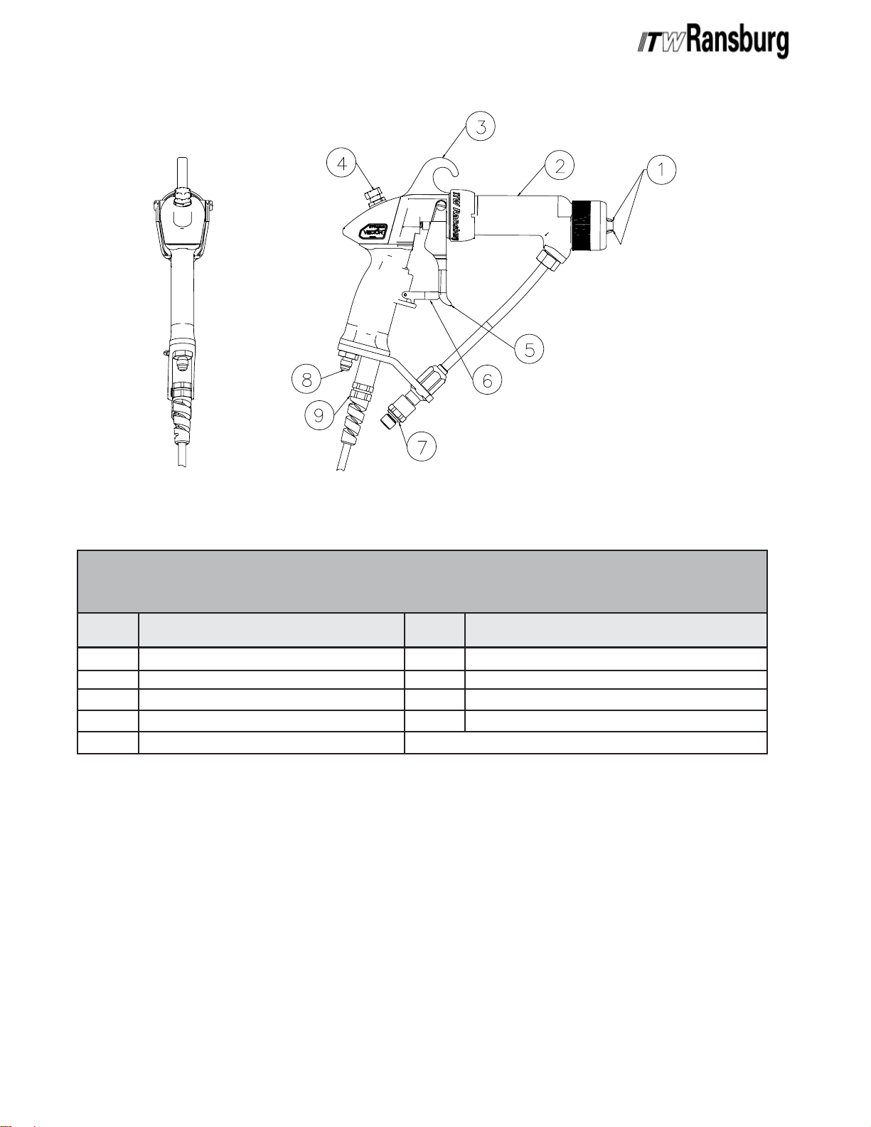
Figure 1: AA90 Cascade Solventborne Electrostatic Spray Applicator Features - Air AssistFigure 1: AA90 Cascade Solventborne Electrostatic Spray Applicator Features - Air Assist
Figure 1: AA90 Cascade Solventborne Electrostatic Spray Applicator Features - Air Assist
Figure 1: AA90 Cascade Solventborne Electrostatic Spray Applicator Features - Air AssistFigure 1: AA90 Cascade Solventborne Electrostatic Spray Applicator Features - Air Assist
AA90 CASCADE SOLAA90 CASCADE SOL
AA90 CASCADE SOL
AA90 CASCADE SOLAA90 CASCADE SOL
APPLICAAPPLICA
APPLICA
APPLICAAPPLICA
No.No.
No.
No.No.
1
2
3
4
5
TT
OR FEAOR FEA
T
OR FEA
TT
OR FEAOR FEA
DescriptionDescription
Description
DescriptionDescription
Cap/Electrode
Barrel, HP
Replaceable Hook
Fan Air Adjust
2-Finger Trigger
VENTBORNE ELECTROSTVENTBORNE ELECTROST
VENTBORNE ELECTROST
VENTBORNE ELECTROSTVENTBORNE ELECTROST
TURES - AIR ASSISTTURES - AIR ASSIST
TURES - AIR ASSIST
TURES - AIR ASSISTTURES - AIR ASSIST
No.No.
No.
No.No.
6
7
8
9
10
DescriptionDescription
Description
DescriptionDescription
Trigger Lock Assembly
Fluid Hose Connection
Air Inlet Connection
Low Voltage Cable Connection
kV Setpoint Switch/Microamp Display
AA
TIC SPRATIC SPRA
A
TIC SPRA
AA
TIC SPRATIC SPRA
YY
Y
YY
AH-07-01.8
1616
16
1616

Vector AA90 Applicatorss - Introduction
Figure 2: 79513-13X Cascade Control Unit FeaturesFigure 2: 79513-13X Cascade Control Unit Features
Figure 2: 79513-13X Cascade Control Unit Features
Figure 2: 79513-13X Cascade Control Unit FeaturesFigure 2: 79513-13X Cascade Control Unit Features
79513-13X CASCADE CONTROL79513-13X CASCADE CONTROL
79513-13X CASCADE CONTROL
79513-13X CASCADE CONTROL79513-13X CASCADE CONTROL
DescriptionDescription
Description
DescriptionDescription
Setpoint Adjust Buttons
kV Setpoint Adjust Button
kV Meter
HV On Indicator
μA Meter
Local/Remote Mode Indicator
1717
17
1717
No.No.
No.
No.No.
1
2
3
4
5
6
UNIT UNIT
UNIT
UNIT UNIT
No.No.
No.
No.No.
7
8
9
10
11
12
FEA FEA
FEA
FEA FEA
DescriptionDescription
Description
DescriptionDescription
Interlock Connector
AC Line Connector
Fuses
Ground Lug
Standard I/O Connector
Low Voltage Cable Connector
TURESTURES
TURES
TURESTURES
AH-07-01.8

Vector AA90 Applicators - Introduction
SPECIFICASPECIFICA
SPECIFICA
SPECIFICASPECIFICA
SOLSOL
SOL
SOLSOL
(C(C
(C
(C(C
Environmental/PhysicalEnvironmental/Physical
Environmental/Physical
Environmental/PhysicalEnvironmental/Physical
Applicator Length:Applicator Length:
Applicator Length: 2.59cm
Applicator Length:Applicator Length:
Weight:Weight:
Weight: 687.5g
Weight:Weight:
Hose and Cable Lengths:Hose and Cable Lengths:
Hose and Cable Lengths: 10m, 15m, 20m,
Hose and Cable Lengths:Hose and Cable Lengths:
Atomizer Assembly:Atomizer Assembly:
Atomizer Assembly: 79581-0XXXX
Atomizer Assembly:Atomizer Assembly:
(See "Nozzle Selection Guide")
ElectricalElectrical
Electrical
ElectricalElectrical
Operating Voltage:Operating Voltage:
Operating Voltage: 85 kV maximum
Operating Voltage:Operating Voltage:
Current Output:Current Output:
Current Output:
Current Output:Current Output:
VENTBORNEVENTBORNE
VENTBORNE
VENTBORNEVENTBORNE
LASSICLASSIC
LASSIC
LASSICLASSIC
Classic:Classic:
Classic: 90 microamperes maximum
Classic:Classic:
))
)
))
TIONSTIONS
TIONS
TIONSTIONS
(10.2-inches)
(1.52 lbs.)
(Classic)
25m, and 30m
79344-14X 9050 POWER79344-14X 9050 POWER
79344-14X 9050 POWER
79344-14X 9050 POWER79344-14X 9050 POWER
SUPPLSUPPL
SUPPL
SUPPLSUPPL
SPECIFICASPECIFICA
SPECIFICA
SPECIFICASPECIFICA
ElectricalElectrical
Electrical
ElectricalElectrical
Input Voltage:Input Voltage:
Input Voltage: 100-240 VAC
Input Voltage:Input Voltage:
Current:Current:
Current: 1 A maximum RMS
Current:Current:
Frequency:Frequency:
Frequency: 50/60 Hz
Frequency:Frequency:
Wattage:Wattage:
Wat t a g e : 40 watts (maximum)
Wattage:Wattage:
Output Voltage:Output Voltage:
Output Voltage: 20-85 kV DC
Output Voltage:Output Voltage:
Current:Current:
Current: 90 microamps (maximum)
Current:Current:
PhysicalPhysical
Physical
PhysicalPhysical
Height:Height:
Height: 16.5cm (6.5-inches)
Height:Height:
Width:Width:
Width: 37.8cm (14.9-inches)
Width:Width:
YY
ELECTRICAL ELECTRICAL
Y
ELECTRICAL
YY
ELECTRICAL ELECTRICAL
TIONSTIONS
TIONS
TIONSTIONS
Paint Resistance:*Paint Resistance:*
Paint Resistance:* .1 MΩ to ∞
Paint Resistance:*Paint Resistance:*
Part Sprayability:Part Sprayability:
Part Sprayability: Determine sprayability of
Part Sprayability:Part Sprayability:
part to be coated using
Model No. 76652 Test
Equipment
(See "Paint, HV and SCI Test Equipment" service
manaul.)
MechanicalMechanical
Mechanical
MechanicalMechanical
Fluid Pressure:Fluid Pressure:
Fluid Pressure: 193 bar (2800 psi)
Fluid Pressure:Fluid Pressure:
(maximum)
Fluid Flow Rate:Fluid Flow Rate:
Fluid Flow Rate: Variable to 1,500 cc/minute
Fluid Flow Rate:Fluid Flow Rate:
(spray tip dependent)
Air Pressure:Air Pressure:
Air Pressure: 6.9 bar
Air Pressure:Air Pressure:
(0-100 psi) (maximum)
Sound LevelSound Level
Sound Level
Sound LevelSound Level
Consumption:Consumption:
Consumption: 83.2 dB(A) @ 2.1 bar
Consumption:Consumption:
(30 psig)
Wetted Parts:Wetted Parts:
Wetted Parts: Nylon, Acetal, Stainless
Wetted Parts:Wetted Parts:
Steel, Teflon, and Carbide
**
*(Use Model No. 76652, Test Equipment)
**
Depth:Depth:
Depth: 30.7cm (12.1-inches)
Depth:Depth:
Weight:Weight:
Weight: 10.2 Kg (22.5 lbs.)
Weight:Weight:
PneumaticPneumatic
Pneumatic
PneumaticPneumatic
Supply Air:Supply Air:
Supply Air: 6.9 bar
Supply Air:Supply Air:
(100 psig) (maximum)
Control Unit Inputs / OutputsControl Unit Inputs / Outputs
Control Unit Inputs / Outputs
Control Unit Inputs / OutputsControl Unit Inputs / Outputs
90509050
9050
90509050
Part #Part #
Part #
Part #Part #
79344-141
79344-142
Control Unit / ApplicatorControl Unit / Applicator
Control Unit / Applicator
Control Unit / ApplicatorControl Unit / Applicator
CombinationsCombinations
Combinations
CombinationsCombinations
90509050
9050
90509050
Part #Part #
Part #
Part #Part #
79344-141
79344-142
VoltageVoltage
Voltage
VoltageVoltage
DesignationDesignation
Designation
DesignationDesignation
110/120 VAC
220/240 VAC
For Use WithFor Use With
For Use With
For Use WithFor Use With
79581-0XXXX
79581-0XXXX
MaximumMaximum
Maximum
MaximumMaximum
OutputOutput
Output
OutputOutput
-85 kV DC
-85 kV DC
AH-07-01.8
1818
18
1818
Vector AA90 Applicators - Introduction
Figure 3: AA90 Classic Solventborne Electrostatic Spray Applicator Features - Air AssistFigure 3: AA90 Classic Solventborne Electrostatic Spray Applicator Features - Air Assist
Figure 3: AA90 Classic Solventborne Electrostatic Spray Applicator Features - Air Assist
Figure 3: AA90 Classic Solventborne Electrostatic Spray Applicator Features - Air AssistFigure 3: AA90 Classic Solventborne Electrostatic Spray Applicator Features - Air Assist
AA90 CLASSIC SOLAA90 CLASSIC SOL
AA90 CLASSIC SOL
AA90 CLASSIC SOLAA90 CLASSIC SOL
APPLICAAPPLICA
APPLICA
APPLICAAPPLICA
No.No.
No.
No.No.
1
2
3
4
5
TT
OR FEAOR FEA
T
OR FEA
TT
OR FEAOR FEA
DescriptionDescription
Description
DescriptionDescription
Cap/Electrode
Barrel, HP
Replaceable Hook
Fan Air Adjust
2-Finger Trigger
VENTBORNE ELECTROSTVENTBORNE ELECTROST
VENTBORNE ELECTROST
VENTBORNE ELECTROSTVENTBORNE ELECTROST
TURES - AIR ASSISTTURES - AIR ASSIST
TURES - AIR ASSIST
TURES - AIR ASSISTTURES - AIR ASSIST
No.No.
No.
No.No.
6
7
8
9
DescriptionDescription
Description
DescriptionDescription
Trigger Lock Assembly
Fluid Hose Connection
Air Inlet Connections
High Voltage Cable Connection
AA
TIC SPRATIC SPRA
A
TIC SPRA
AA
TIC SPRATIC SPRA
YY
Y
YY
1919
19
1919
AH-07-01.8

Vector AA90 Applicators - Introduction
Figure 4: 79344-14X 9050 Power Supply FeaturesFigure 4: 79344-14X 9050 Power Supply Features
Figure 4: 79344-14X 9050 Power Supply Features
Figure 4: 79344-14X 9050 Power Supply FeaturesFigure 4: 79344-14X 9050 Power Supply Features
79344-14X 9050 POWER SUPPL79344-14X 9050 POWER SUPPL
79344-14X 9050 POWER SUPPL
79344-14X 9050 POWER SUPPL79344-14X 9050 POWER SUPPL
No.No.
No.
No.No.
1
2
3
4
5
6
7
8
AH-07-01.8
DescriptionDescription
Description
DescriptionDescription
kV Meter
High Voltage On Indicator
Reset Button
μA Meter
Fault Indicator
On-Off Switch
Local Remote Mode Indicator
"One Touch" kV Setpoint Button
YY
FEA FEA
Y
FEA
YY
FEA FEA
No.No.
No.
No.No.
9
10
11
12
13
14
15
16
TURESTURES
TURES
TURESTURES
DescriptionDescription
Description
DescriptionDescription
kV Setpoint/Adjust Buttons
Air Flow Switch Connections (Low Flow)
High Voltage Cable Connector
Standard I/O Connector
Fuses
Ground Lug
AC Inlet Receptable
Interlock I/O Connector
2020
20
2020

Vector AA90 Applicators - Installation
INSTINST
INST
INSTINST
> Install and route the hoses and cable
so they are
tures in excess of 120°F and so that all
hose bends are
6-inch (15 cm) radius. Failure to comply
with these guidelines could cause equipment malfunctions that might create
HAZARDOUS CONDITIONS!HAZARDOUS CONDITIONS!
HAZARDOUS CONDITIONS!
HAZARDOUS CONDITIONS!HAZARDOUS CONDITIONS!
This information is intended ONLY to indicate
general installation guidelines of this product and
its working relationship to other ITW Ransburg
system components. Each installation is unique
and should be directed by an ITW Ransburg
representative.
SAFE INSTSAFE INST
SAFE INST
SAFE INSTSAFE INST
ALLAALLA
ALLA
ALLAALLA
W A R N I N GW A R N I N G
W A R N I N G
W A R N I N GW A R N I N G
!!
!
!!
NOTNOT
NOT exposed to tempera-
NOTNOT
TIONTION
TION
TIONTION
NOT LESSNOT LESS
NOT LESS than a
NOT LESSNOT LESS
ALLAALLA
ALLA
ALLAALLA
TIONTION
TION
TIONTION
• Position all non-approved electrical apparatus
(including, but not limited to, high voltage power
supplies, fluid pumps, and air compressors)
outside of the hazardous location. See the
appropriate country or local codes.
• Provide appropriate fire extinguishing equipment.
• Provide conductive flooring in all spray areas.
TYPICAL AA90 CASCADETYPICAL AA90 CASCADE
TYPICAL AA90 CASCADE
TYPICAL AA90 CASCADETYPICAL AA90 CASCADE
APPLICAAPPLICA
APPLICA
APPLICAAPPLICA
INSTINST
INST
INSTINST
Connect the low voltage cable to the control unit low
voltage socket. Gently hand tighten the cable retaining
nut. Connect the other end of the low voltage cable to
the applicator, using a wrench to tighten. Slide the cable
boot over the nut.
ALLAALLA
ALLA
ALLAALLA
TT
OROR
T
OR
TT
OROR
TIONTION
TION
TIONTION
• Ground the spray booth, the paint supply, and
the conveyor or work support.
• Ground all solvent and waste safety containers.
• Ground all work holders and hooks and keep
them free of paint.
• Ground the target object to a structural ground
and not back to the applicator system. Ensure
that all target objects have a resistance to
ground of one megohm or LESS.
C A U T I O NC A U T I O N
C A U T I O N
C A U T I O NC A U T I O N
!!
!
!!
> Target grounding wire must not be
connected directly to the ground lug of the
9050. A seperate ground line must be
used for each connection.
• Ensure that all elements of the coating system
are correctly grounded, connected, and located.
C A U T I O NC A U T I O N
C A U T I O N
C A U T I O NC A U T I O N
!!
!
!!
DO NOT DO NOT
>
DO NOT overtighten the low voltage
DO NOT DO NOT
cable connection to the applicator. Damage to plastic parts may occur.
The control unit may be connected through conduit
with an explosion-proof switch on or near the
spray booth where it will be convenient to the
operator, or may be connected with a power cord
depending upon application requirement.
2121
21
2121
AH-07-01.8

Vector AA90 Applicators - Installation
R<1 Meg Ohm
TYPICALTYPICAL
TYPICAL
TYPICALTYPICAL
FEAFEA
FEA
FEAFEA
No.No.
No.
No.No.
1
2
3
4
5
6
7
AH-07-01.8
Figure 5: Typical AA90 Cascade Applicator Installation FeaturesFigure 5: Typical AA90 Cascade Applicator Installation Features
Figure 5: Typical AA90 Cascade Applicator Installation Features
Figure 5: Typical AA90 Cascade Applicator Installation FeaturesFigure 5: Typical AA90 Cascade Applicator Installation Features
AA90 CASCADE APPLICA AA90 CASCADE APPLICA
AA90 CASCADE APPLICA
AA90 CASCADE APPLICA AA90 CASCADE APPLICA
TURESTURES
TURES
TURESTURES
DescriptionDescription
Description
DescriptionDescription
AC Line Cord (110/220)
9050 Control Unit
Vector Applicator
Ball Valve
Air Regulator W/Pressure Gauge
Air/Water Separator
Main Air Supply
No.No.
No.
No.No.
8
9
10
11
12
13
14
TT
OR INSTOR INST
T
OR INST
TT
OR INSTOR INST
DescriptionDescription
Description
DescriptionDescription
Fluid Supply (Grounded)
Fluid Regulator
Air Line
Low Voltage Cable
Fluid Line
Target (Earth or Building Ground)
9050 Ground (Seperate Earth or Building Ground)
ALLAALLA
ALLA
ALLAALLA
TIONTION
TION
TIONTION
2222
22
2222
 Loading...