

SERVICE MANUAL
AH-08-04.2
(REPALACE: AH-08-04.1)
February - 2013
Ransburg
TM
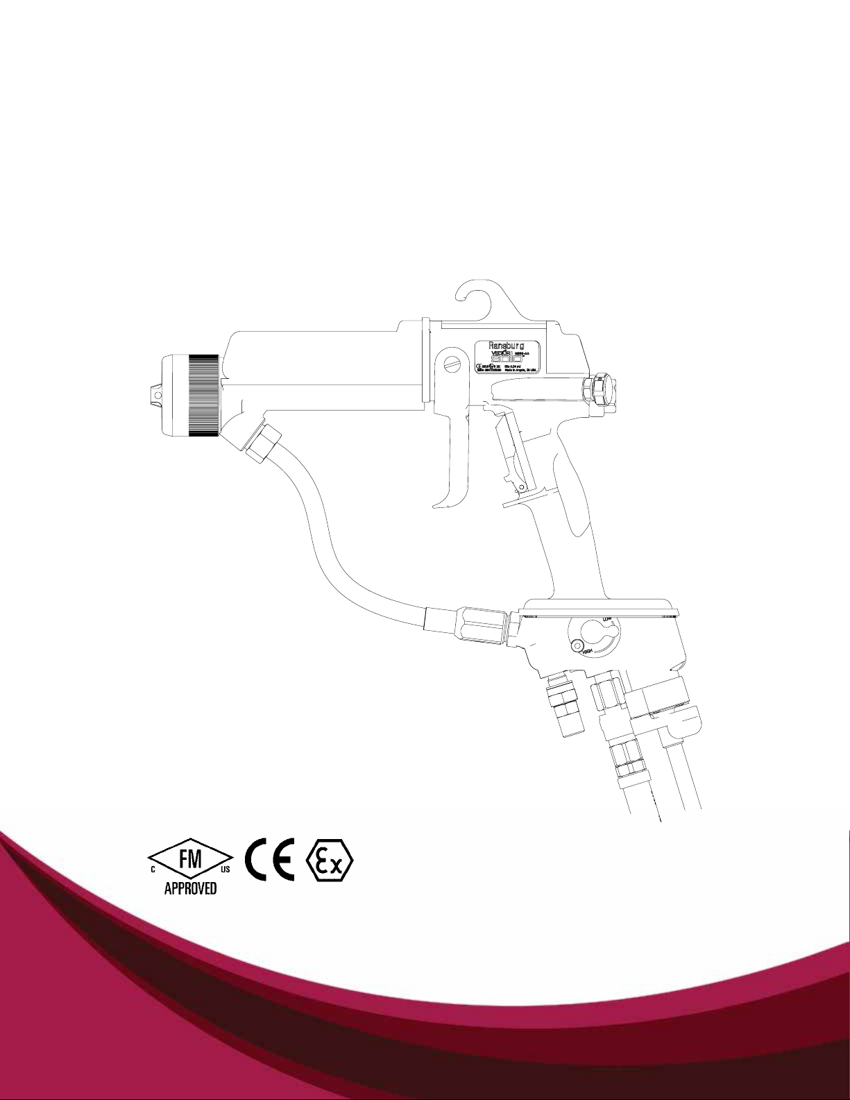
VECTOR SOLO
AA90 APPLICATORS
MODELS: 79698
IMPORTANT: Before using this equipment,
carefully read SAFETY PRECAUTIONS, starting
on page 1, and all instructions in this manual.
Keep this Service Manual for future reference.
Service Manual Price: $50.00 (U.S.)

Vector Solo AA90 Applicators
NOTE: This manual has been changed from revision AH-08-04.1 to revision AH-08-04.2.
Reasons for this change are noted under “Manual Change Summary” inside the
back cover of this manual.
Ransburg
AH-08-04.2

Ransburg
Vector Solo AA90 Applicators - Contents
CONTENTS
SAFETY: 1-4
SAFETY PRECAUTIONS ......................................................................................................1
HAZARDS / SAFEGUARDS ..................................................................................................2-4
ATEX/FM: 5-8
EUROPEAN ATEX DIRECTIVE ............................................................................................ 5
EUROPEAN ATEX LABELS .................................................................................................. 6
FM CONFIGURATION DRAWING ........................................................................................ 7-8
INTRODUCTION: 9-12
GENERAL DESCRIPTION ....................................................................................................9
79698 VECTOR SOLO AA90 SPECIFICATIONS .................................................................10
VECTOR SOLO AA90 SOLVENTBORNE ELECTROSTATIC SPRAY APPLICATOR ..........11
VECTOR SOLO AA90 TYPICAL SOLVENTBORNE INSTALLATION ....................................12
PAGE
INSTALLATION: 13-14
79698 SOLO SOLVENTBORNE INSTALLATION .................................................................13-14
INSTALLATION .....................................................................................................................14
OPERATION: 16-20
SAFE OPERATION ...............................................................................................................16-18
FLUSHING / COLOR CHANGE PROCEDURE ....................................................................18-19
THE RIGHT TECHNIQUE ......................................................................................................19
PREPARATION ......................................................................................................................20
MAINTENANCE: 21-43
SUITABLE SOLVENTS FOR CLEANING VECTOR SOLO APPLICATORS .........................21
ROUTINE SCHEDULE ..........................................................................................................22-23
APPLICATOR REPAIR ..........................................................................................................23
FLUSHING PROCEDURES ...................................................................................................24
APPLICATOR ASSEMBLY CLEANING PROCEDURE ..........................................................24-27
BARREL REMOVAL ...............................................................................................................27-30
NEEDLE SHAFT REMOVAL/REPLACEMENT ......................................................................31-37
TEST AND MAINTENANCE KIT USAGE (79870-00) ............................................................37-40
TROUBLESHOOTING GUIDE ...............................................................................................41-43
PARTS IDENTIFICATION: 44-51
79698 VECTOR SOLO AA90 APPLICATOR MODEL IDENTIFICATION .............................. 44
AIR HOSE LENGTH AND TYPE .......................................................................................... 44
TRIGGER TYPE .................................................................................................................... 45
SPRAY TIP SIZE .................................................................................................................. 45
FLUID HOSE LENGTH ........................................................................................................ 45
(Continued On Next Page)
AH-08-04.2

Vector Solo AA90 Applicators - Contents
Ransburg
CONTENTS (Cont.)
PARTS IDENTIFICATION (Cont.): 44-51
VECTOR SOLO AA90 SOLVENTBORNE APPLICATOR PARTS BREAKDOWN .................. 46
VECTOR SOLO AA90 SOLVENTBORNE APPLICATOR PARTS LIST .................................. 47-48
POWER MODULE REPLACEABLE PARTS - PARTS LIST ...................................................48
AIR HOSE ASSEMBLY PARTS LIST ...................................................................................... 49
HIGH PRESSURE WHIP AND FITTING PARTS LIST ............................................................ 49
NEEDLE SHAFT ASSEMBLY PARTS LIST ............................................................................50
FLUID HOSE PARTS LIST ......................................................................................................50
TEST AND MAINTENANCE KIT ............................................................................................. 51
VECTOR SOLO AA90 APPLICATOR RECOMMENDED SPARE PARTS .............................. 51
WARRANTY POLICIES: 52
LIMITED WARRANTY ............................................................................................................. 52
AH-08-04.2
Ransburg
SAFETY
Vector Solo AA90 Applicators - Safety
SAFETY PRECAUTIONS
Before operating, maintaining or servicing any
Ransburg electrostatic coating system, read and
understand all of the technical and safety literature for your Ransburg products. This manual
contains information that is important for you to
know and understand. This information relates to
USER SAFETY and PREVENTING EQUIPMENT
PROBLEMS. To help you recognize this information, we use the following symbols. Please pay
particular attention to these sections.
A WARNING! States information to alert you
to a situation that might cause serious injury
if instructions are not followed.
A CAUTION! States information that tells how
to prevent damage to equipment or how to
avoid a situation that might cause minor injury.
A NOTE is information relevant to the procedure in progress.
W A R N I N G
!
The user MUST read and be familiar
with the Safety Section in this manual and
the Ransburg safety literature therein iden-
tied.
This hand held device is intended to be
used by trained personnel ONLY.
This manual MUST be read and thor-
oughly understood by ALL personnel who
operate, clean or maintain this equipment!
Special care should be taken to ensure that
the WARNINGS and safety requirements
for operating and servicing the equipment
are followed. The user should be aware of
and adhere to ALL local building and re
codes and ordinances as well as NFPA-
33 EN 50176 SAFETY STANDARD, or
applicable country safety standards pri-
or to installing, operating, and/or servicing
this equipment.
While this manual lists standard specications
and service procedures, some minor deviations
may be found between this literature and your
equipment. Differences in local codes and plant
requirements, material delivery requirements,
etc., make such variations inevitable. Compare
this manual with your system installation drawings
and appropriate Ransburg equipment manuals to
reconcile such differences.
Careful study and continued use of this manual will
provide a better understanding of the equipment
and process, resulting in more efcient operation,
longer trouble-free service and faster, easier troubleshooting. If you do not have the manuals and
safety literature for your Ransburg system, contact
your local Ransburg representative or Ransburg.
W A R N I N G
!
The hazards shown on the following
page may occur during the normal use of
this equipment. Please read the hazard
chart beginning on page 2.
AH-08-04.2
1
Vector Solo AA90 Applicators - Safety
Ransburg
AREA
Tells where hazards
may occur.
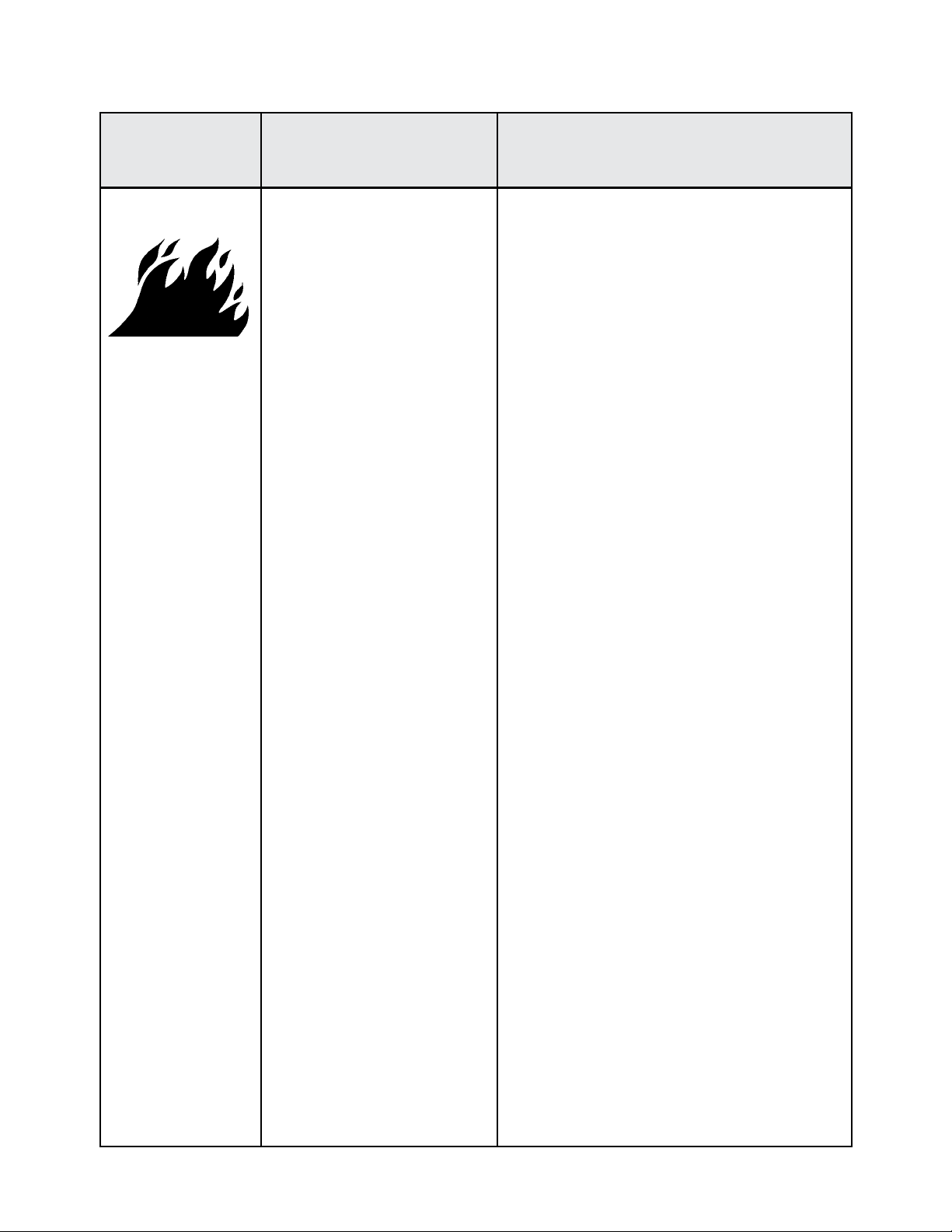
Spray Area
HAZARD
Tells what the hazard is.
Fire Hazard
Improper or inadequate operation and maintenance proce-
dures will cause a re hazard.
Protection against inadvertent
arcing that is capable of causing
re or explosion is lost if any
safety interlocks are disabled
during operation. Frequent power supply shutdown indicates a
problem in the system requiring
correction.
SAFEGUARDS
Tells how to avoid the hazard.
Fire extinguishing equipment must be present in
the spray area and tested periodically.
Spray areas must be kept clean to prevent the
accumulation of combustible residues.
Smoking must never be allowed in the spray
area.
The high voltage supplied to the atomizer must
be turned off prior to cleaning, ushing or maintenance.
When using solvents for cleaning:
• Those used for equipment ushing should
have ash points equal to or higher than
those of the coating material.
• Those solvents used for cleaning must have
a ash point at minimum of 5
than the ambient temperature. It is the end
users responsibility to insure this condition is
met.
o
C (9oF) greater
Spray booth ventilation must be kept at the rates
required by NFPA-33, OSHA, country, and local
codes. In addition, ventilation must be maintained during cleaning operations using ammable or combustible solvents.
Electrostatic arcing must be prevented. Safe
sparking distance must be maintained between
the parts being coated and the applicator. A distance of 1 inch for every 10KV of output voltage
is required at all times.
Test only in areas free of combustible material.
Testing may require high voltage to be on, but
only as instructed.
Non-factory replacement parts or unautho-
rized equipment modications may cause re or
injury.
If used, the key switch bypass is intended for
use only during setup operations. Production
should never be done with safety interlocks disabled.
Never use equipment intended for use in waterborne installations to spray solvent based materials.
The paint process and equipment should be
set up and operated in accordance with NFPA33, NEC, OSHA, local, country, and European
Health and Safety Norms.
2
AH-08-04.2
Ransburg
Vector Solo AA90 Applicators - Safety
AREA
Tells where hazards
may occur.
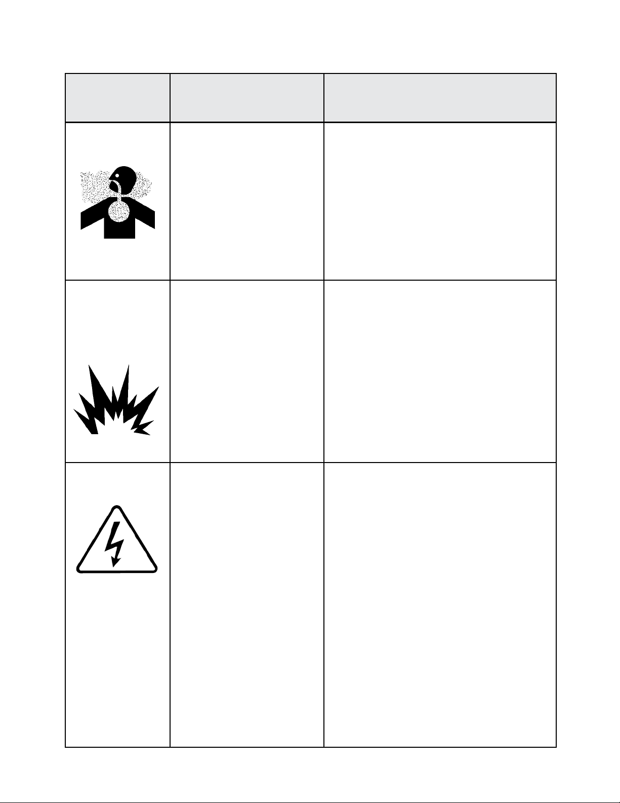
Toxic
Substances
Explosion Hazard /
Incompatible Materials
HAZARD
Tells what the hazard is.
Certain material may be harmful
if inhaled, or if there is contact
with the skin.
Halogenated hydrocarbon sol-
vents, for example: methylene
chloride and 1,1,1, - Trichloroethane, are not chemically
compatible with the aluminum
that might be used in many system components. The chemical
reaction caused by these solvents reacting with aluminum
can become violent and lead to
an equipment explosion.
SAFEGUARDS
Tells how to avoid the hazard.
Follow the requirements of the Material Safety Data
Sheet supplied by coating material manufacturer.
Adequate exhaust must be provided to keep the
air free of accumulations of toxic materials.
Use a mask or respirator whenever there is a
chance of inhaling sprayed materials. The mask
must be compatible with the material being sprayed
and its concentration. Equipment must be as pre-
scribed by an industrial hygienist or safety expert,
and be approved.
Spray applicators require that aluminum inlet ttings
be replaced with stainless steel. (See "Accessories" list) Aluminum is widely used in other spray
application equipment - such as material pumps,
regulators, valves, etc. Check all other equipment
items before use and make sure they can also be
used safely with these solvents. Read the label
or data sheet for the material you intend to spray.
If in doubt as to whether or not a coating or cleaning material is compatible, contact your material
supplier. Any other type of solvent may be used
with aluminum equipment.
AH-08-04.2
Electrical
Equipment
High voltage equipment is utilized. Arcing in areas of ammable or combustible mat-erials
may occur. Personnel are
exposed to high voltage during
operation and maintenance.
Protection against inadvertent
arcing that may cause a re or
explosion is lost if safety circuits
are disabled during operation.
An electrical arc can ignite coat-
ing materials and cause a re or
explosion.
Turn the power module OFF before working on
the equipment.
Test only in areas free of ammable or combustible material.
Testing may require high voltage to be on, but
only as instructed.
Production should never be done with the safety
circuits disabled.
Before turning the high voltage on, make sure
no objects are within the sparking distance.
3
Vector Solo AA90 Applicators - Safety
Ransburg
AREA
Tells where hazards
may occur.
Spray Area
HAZARD
Tells what the hazard is.
Electrostatic Arcing Never operate the applicator without properly
SAFEGUARDS
Tells how to avoid the hazard.
grounding the following.
A. Operators
Operators must be grounded. Rubber soled
insulating shoes should not be worn. Grounding
leg or wrist straps may be used.
Operators must maintain contact with the handle
of the applicator. If work gloves are used, the
palm section must be cut out.
Operators must remove from themselves all
metal objects that are not grounded.
NOTE: REFER TO NFPA-33 REGARDING
OPERATOR GROUNDING OR SPECIFIC COUNTRY SAFETY CODE.
B. Parts being sprayed. Resistance between the
part and a grounded conveyor must not exceed
1 megohm.
General Use and
Maintenance
Improper operation or maintenance may create a hazard.
Personnel must be properly
trained in the use of this equipment.
C. Every metal and conductive object in the spray
area. This includes the booth, parts hangers,
re extinguishers, conductive ooring, etc.
Grounded conductive ooring must be provided
in the spray area.
Turn off voltage at the power module before ushing out, cleaning, or removing any parts from the
applicator.
Never install an applicator into a uid system using
an isolated solvent supply.
Do not touch applicator electrode while applicator
is energized.
Personnel must be given training in accordance
with the requirements of NFPA-33.
Instructions and safety precautions must be read
and understood prior to using this equipment.
Comply with appropriate local, state, and national
codes governing ventilation, re protection, operation maintenance, and housekeeping.
4
AH-08-04.2

Ransburg
Vector Solo AA90 Applicators - Atex/FM
EUROPEAN ATEX DIRECTIVE 94/9/EC, ANNEX II, 1.0.6
The following instructions apply to equipment
covered by certicate number Sira 08ATEX5060:
1. The equipment may be used with ammable
gases and vapors with apparatus groups II and
with temperature class T6.
2. The equipment is only certied for use in ambient temperatures in the range 0°C to +40°C and
should not be used outside this range.
3. Installation shall be carried out by suitably trained
personnel in accordance with the applicable code
of practice e.g. EN 60079-14:1997.
4. Inspection and maintenance of this equipment
shall be carried out by suitably trained personnel
in accordance with the applicable code of practice
e.g. EN 60079-17.
5. Repair of this equipment shall be carried out by
suitable trained personnel in accordance with the
applicable code of practice e.g. EN 60079-19.
6. Putting into service, use, assembling, and
adjustment of the equipment shall be tted by
suitably trained personnel in accordance with the
manufacturer's documentation.
Refer to the "Table of Contents" of this service
manual:
a. Installation
b. Operation
c. Maintenance
d. Parts Identication
7. Components to be incorporated into or used as
replacement parts of the equipment shall be tted
by suitably trained personnel in accordance with
the manufacturer's documentation.
8. The certication of this equipment relies upon
the following materials used in its construction:
If the equipment is likely to come into contact with
aggressive substances, then it is the responsibility
of the user to take suitable precautions that prevent
it from being adversely affected, thus ensuring that
the type of protection provided by the equipment
is not compromised.
Aggressive substances: e.g. acidic liquids or gases
that may attack metals, or solvents that may affect
polymeric materials.
Suitable precautions: e.g. regular checks as part
of routine inspections or establishing from the
material's data sheets that it is resistant to specic
chemicals.
Refer to "Specications" in the "Introduction"
section:
a. All uid passages contain stainless steel
or nylon ttings.
b. High voltage cascade is encapsulated with
a solvent resistant epoxy.
9. A recapitulation of the certication marking is
detailed in the "ATEX" section, on the next page,
drawing numbers: 79852-02 and 79864-02.
10. The characteristics of the equipment shall
be detailed e.g. electrical, pressure, and voltage
parameters.
The manufacturer should note that, on being
put into service, the equipment must be accompanied by a translation of the instructions
in the language or languages of the country in
which the equipment is to be used and by the
instructions in the original language.
AH-08-04.2
5
Vector Solo AA90 Applicators - Atex/FM
Ransburg
Vector Solo AA90 79698 ATEX
Product Marking Denitions
Ex Certicate Number: Sira 08ATEX5060
Sira = Notied Body performing EC-type
examination
08 = Year of certication
ATEX = Reference to ATEX Directive
5 = Protection Concept Code (code 5 is titled
Encapsulation)
060 = Document serial number
X = Special conditions for safe use apply
Special conditions for safe use: The Vector Solo
AA90 79698 Applicators shall only be used with
associated Ransburg 79727-XX Air Hose Assembly. It is the end users responsibility to insure the
air hose is properly grounded to true earth ground.
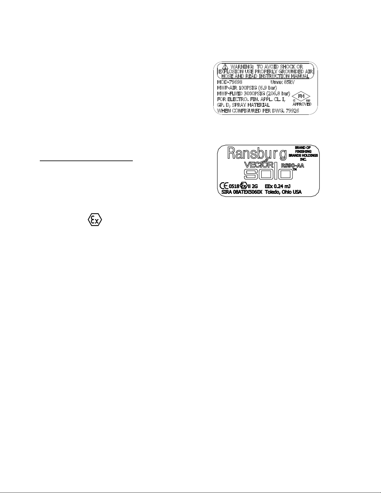
Product Marking
II 2 G
Label 79852-02
Label 79846-02
Ex = Specic marking of explosive protection
II = Equipment Group hazardous area charac-teristics
2 = Equipment Category
G = Type of explosive atmosphere (gases, vapors,
or mists)
EEx 0.24mJ = The Vector Solo AA90 79698
Applicators are suitable for use in manual spraying
installations complying with EN 50 050 as they
are a Type A class with a discharge energy limit
of 0.24mJ.
FM Conguration
This applicator is FM approved when congured to
drawing 79926 shown on page 7 and 8.
6
AH-08-04.2
Ransburg
Vector Solo AA90 Applicators - Atex/FM
VECTOR SOLO RS90-AA SOLVENT BASED
79698 - ABCDE
BASE
MODEL NO.
(ORDERING INFORMATION ONLY)
OPTION
DESIGNATIONS
"E" DESIGNATIONS
"C" DESIGNATIONS
"D" DESIGNATIONS
"B" DESIGNATIONS
AH-08-04.2
"A" DESIGNATIONS
CONFIGURATION DWG. 79926 REV A
7
Vector Solo AA90 Applicators - Atex/FM
VECTOR SOLO RS90-AA SOLVENT BASED
1009 TIP : 79691-1009, 1013 TIP : 79691-1013, 1018
1311 TIP : 79691-1311, 1313 TIP : 79691-1313, 1315
1511 TIP : 79691-1511, 1513 TIP : 79691-1513, 1515 TIP : 796911715
1
2
3
0 FOR NO FLUID
1 FOR 11m (36FT) FLUID HOSE
2 FOR 15m (50FT) FLUID HOSE
3 FOR 25m (75FT) FLUID HOSE
79698 - ABCDE
BASE
OPTION "A" DESIGNATIONS
AIR HOSE TYPE AND LENGTH
1 FOR STANDARD AIR HOSE ASSEMBLY, 10 METER (33')-PART NUMBER: 79727-10
2 FOR STANDARD AIR HOSE ASSEMBLY, 15 METER (49')-PART NUMBER: 79727-15
3 FOR STANDARD AIR HOSE ASSEMBLY, 20 METER (66')-PART NUMBER: 79727-20
4 FOR STANDARD AIR HOSE ASSEMBLY, 30 METER (99')-PART NUMBER: 79727-30
5 FOR QD AIR HOSE ASSEMBLY, 10 METER (33')-PART NUMBER: 79727-11
6 FOR QD AIR HOSE ASSEMBLY, 15 METER (49')-PART NUMBER: 79727-16
7 FOR QD AIR HOSE ASSEMBLY, 20 METER (66')-PART NUMBER: 79727-21
8 FOR QD AIR HOSE ASSEMBLY, 30 METER (99')-PART NUMBER: 79727-31
MODEL NO.
(ORDERING INFORMATION ONLY)
Ransburg
OPTION
DESIGNATIONS
OPTION "B" DESIGNATIONS
0 FOR FLUID INLET TUBE (INCLUDED)-PART NUMBER: 79921-00
OPTION "C" DESIGNATIONS
2 FOR TWO FINGER TRIGGER-PART NUMBER: 79694-00
FOR 0811 TIP WITHOUT PREORIFICE-PART NUMBER: 79691-0811
FOR 0813 TIP WITHOUT PREORIFICE-PART NUMBER: 79691-0813
FOR 1011 TIP WITHOUT PREORIFICE-PART NUMBER: 79691-1011
4 FOR 1015 TIP WITHOUT PREORIFICE-PART NUMBER: 79691-1015
0509 TIP : 79691-0509, 0511 TIP : 79691-0511, 0513 TIP : 79691-0513
TIP : 79691-1715
4 FOR 30m (100FT) FLUID HOSE-PART NUMBER: 7994-100
FLUID INLET TUBE
TRIGGER TYPE
OPTION "D" DESIGNATIONS
SPRAY TIP SIZE
OPTION "E" DESIGNATIONS
FLUID HOSE LENGTH
HOSE
-PART NUMBER: 7994-36
-PART NUMBER: 7994-50
-PART NUMBER: 7994-75
APPROVED SPARE TIP LIST
TIP : 79691-1018, 1021 TIP : 79691-1021
TIP : 79691-1315, 1318 TIP : 79691-1318
1515, 1518 TIP : 79691-1518, 1521 TIP : 79691-1521,
8
CONFIGURATION DWG. 79926 REV A
AH-08-04.2

Ransburg
INTRODUCTION
Vector Solo AA90 Applicators - Introduction
GENERAL DESCRIPTION
The Vector Solo
bined air/airless powered only by a pressurized
air source. Pressurized air creates rotation of a
turbine generator that powers a cascade. The
cascade generates a high voltage DC charge
to the electrode creating an electrostatic eld
between the atomizer and the target. The target
is electrically grounded through its support which
may be either stationary or moving.
A regulated pressure uid system delivers coating
material to the atomizer. At the time of triggering
the applicator, fan and atomization air is introduced,
which atomizes the coating material into a spray
mist. The atomized spray particles under the inuence of the electrostatic eld become electrically
charged. The charged particles are attracted to,
and deposited on, the target object. The forces
between the charged particles and the grounded
target are sufcient to turn most normal overspray
around and deposit it on the back surface of the
target. Therefore, a high percentage of the coating
is deposited on the target.
TM
AA90 Applicators are a com-
NOTES
One of the many features of the Vector Solo AA90
applicator system is that the electrical energy,
which is available from the resistive charging
electrode, is limited to the optimum level of safety
and efciency. The system is incapable of releasing sufcient electrical or thermal energy during
normal operating conditions to cause ignition of
specic hazardous materials in their most easily
ignited concentrations in air.
As the applicator electrode approaches ground,
applicator circuitry causes the high voltage to
approach zero while the current approaches its
maximum value.
AH-08-04.2
9

Vector Solo AA90 Applicators - Introduction
79698 VECTOR SOLO AA90 SPECIFICATIONS
Ransburg
Environmental/Physical
Applicator Length: 269mm (10.6-inches)
Weight: 973 grams (31.0 oz.)
Hose 79727-XX
Lengths (Std): 10m, 15m, 20m, and 30m
Atomizer Nozzle
Assembly (Std): 79691-XXXX
(See "Nozzle Selection Guide")
Electrical
Operating Voltage: 85kV DC (-) maximum
Current Output:
Paint Resistance:* .1 MW to ∞
*(Use Model No. 76652, Test Equipment)
Part Sprayability: Determine sprayability of
part to be coated using
76652, Test Equipment
(See current "Paint, HV & SCI Test Equipment"
service manual.)
130 microamperes maximum
Mechanical
Fluid Flow
Capacity: Variable to 1,500 cc/minute
(spray tip dependent)
Wetted Parts: Stainless, polyethylene,
nylon, acetal polymer,
tungsten carbide
Operating Pressure
Fluid: 207 bar (0-3000 psi) Max.
Air: 6.9 bar (0-100 psi) Max.
Ambient Temp.: 40°C to 0°C
(104°F to 32°F)
Consumption: 205 SLPM (7.2 SCFM) @
2.8 bar (40 psig) @ Handle
Inlet
Sound Level: 92dB (A) @ 2.8 bar
(40 psig) Inlet,
1m from applicator
Vibration Level: 0.065 m/S2 @ 2.8 bar (40
psig) @ Handle Inlet
10
AH-08-04.2
Ransburg
Vector Solo AA90 Applicators - Introduction
3
2
1
4
10
5
13
12
8
11
6
7
9
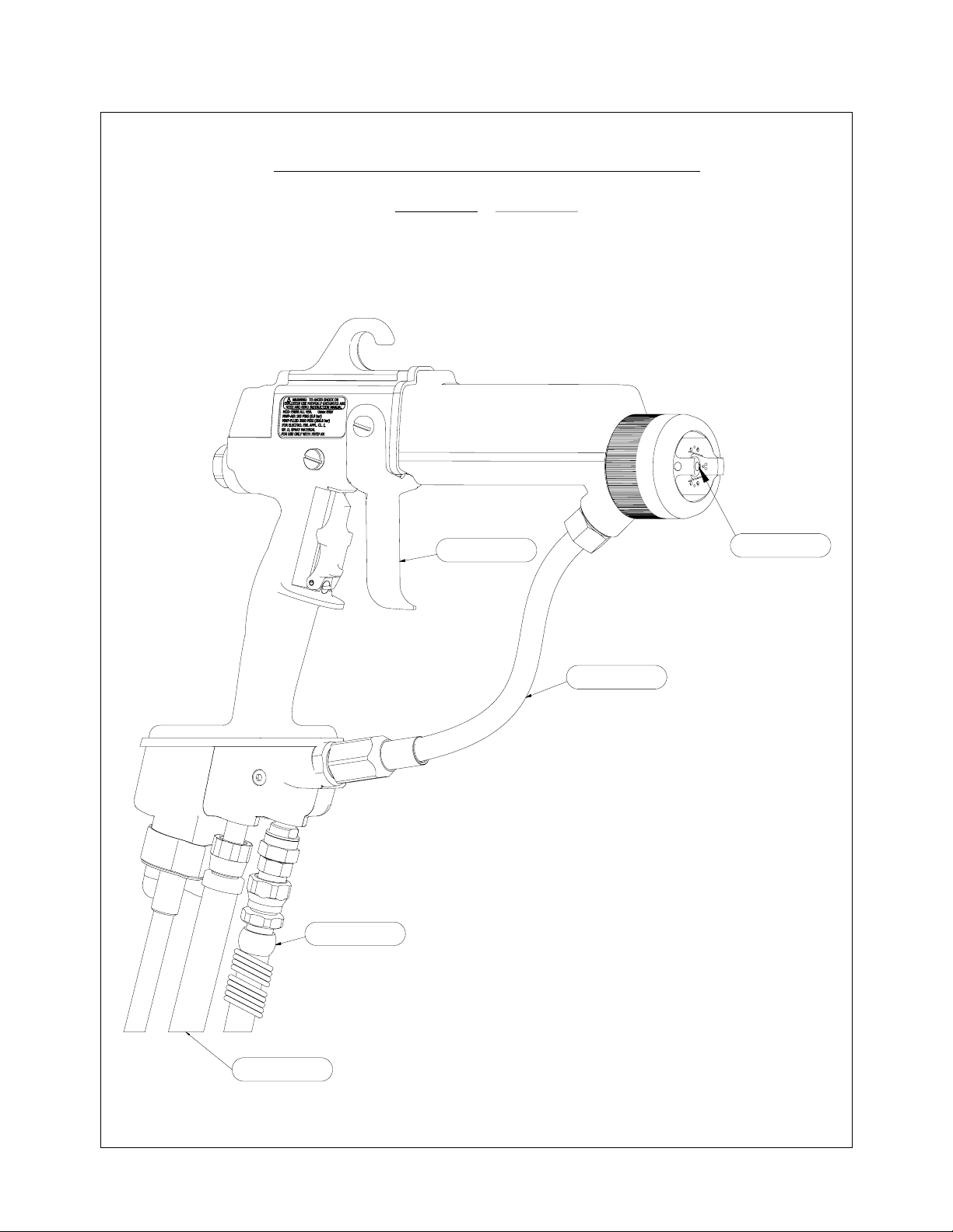
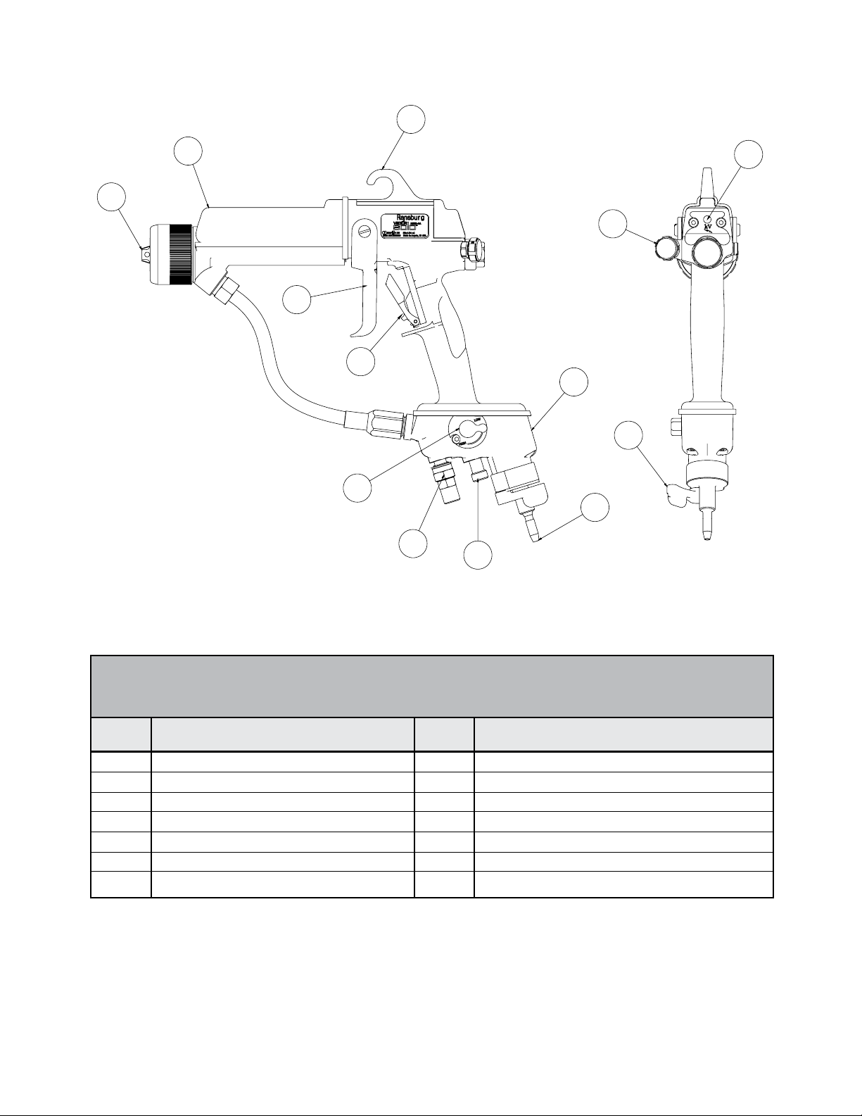
Figure 1: Vector Solo AA90 Solventborne Electrostatic Spray Applicator
VECTOR SOLO AA90 SOLVENTBORNE ELECTROSTATIC SPRAY APPLICATOR
No.
1
2
3
4
5
6
7
Description
Air Cap / Spray Tip
Barrel
Replaceable Hook
Fan Air Adjustment
Trigger Lock
Fluid Hose Connection
Air Inlet Connection
No.
8
9
10
11
12
13
kV Setpoint Switch
Voltage On/Off Indicator Light
Trigger
Turbine Air Exhaust
Voltage On/Off Lever
Power Module
Description
AH-08-04.2
11
Vector Solo AA90 Applicators - Introduction
Ransburg
12
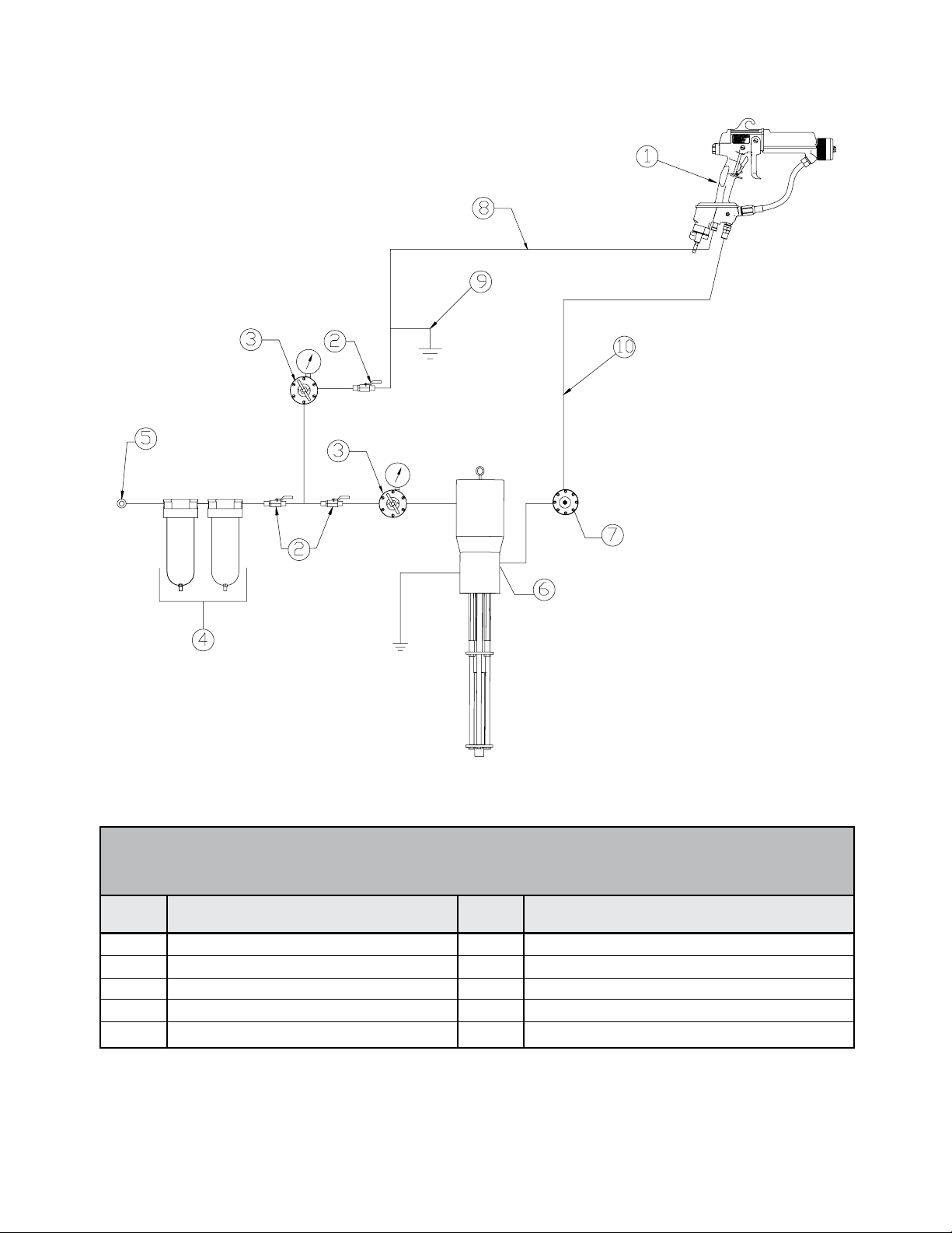
Figure 2: Vector Solo AA90 Typical Solventborne Installation
VECTOR SOLO AA90 TYPICAL SOLVENTBORNE INSTALLATION
No.
1
2
3
4
5
Description
Vector Solo Applicator
Ball Valve
Air Regulator W/Pressure Gauge
Air/Water Separator
Main Air Supply Line
No.
6
7
8
9
10
Fluid Supply (Grounded)
Fluid Regulator
Air Hose (79727-XX)
Air Hose Ground Wire
Fluid Line
Description
AH-08-04.2
Ransburg
INSTALLATION
Vector Solo AA90 Applicators - Installation
Air Hose
For the Vector Solo AA90 to properly function
safely, the 79727-XX Air Hose assembly with
ground wire is required to be used.
W A R N I N G
!
For proper safe function of the applicator,
the 79727-XX Air Hose must be used either
standard or quick disconnect style.
Fluid Hose Recommendation
Ransburg recommends using a 7994-XX Fluid
Hose Assembly. This assembly is made to spe-
cically t the uid tting size engineered into the
applicator. This hose is available as a standard
conguration or as a replacement from your authorized Ransburg distributor.
C A U T I O N
!
Any user installed uid hose used must
be rated for 207 bar (3000 psig) working
pressure minimum.
Filters
1. Install an air lter assembly on the outlet of the
main air regulator. The lter should be 5 micron
with a maximum working pressure of at least
100 psig (6.9 bar). Screw the tting into the lter
inlet. The lter MUST be installed with the arrow
pointing in the direction of ow. (Refer to the ap-
propriate Filter Assembly manual for Installation
Instruc-tions.)
79698 SOLO SOLVENTBORNE INSTALLATION
W A R N I N G
!
The user MUST read and be familiar with
the "Safety" section of this manual.
This hand held device is intended to be
used by trained personnel ONLY.
This manual MUST be read and thor-
oughly understood by ALL personnel who
operate, clean, or maintain this equipment!
Special care should be taken to ensure that
the warnings and requirements for operating
and servicing safely are followed. The user
should be aware of and adhere to ALL local
building and re codes and ordinances as
well as NFPA, OSHA, and all related country safety codes prior to installing, operating,
and/or servicing this equipment.
Personnel MUST be GROUNDED to pre-
vent a shock or spark during electrostatic operation.
Install and route the hoses so they are
NOT exposed to temperatures in excess of
49°C (120° F) and so that all hose bends are
NO LESS than a (6-inch) (15cm) radius. Failure to comply with these parameters could
cause equipment malfunction that might create HAZARDOUS CONDITIONS!
2. Ransburg recommends that a uid lter be
installed at the output of the uid supply (pump,
circulating system, etc.). It is the end user's re-
sponsibility to install the proper lter that meets
their system's requirements.
AH-08-04.2
13
Vector Solo AA90 Applicators - Installation
Interlocks Required
Interlock the solvent supply with the main supply
air to the applicator. When solvent is On, main
supply air to the applicator is Off. Interlocks are
user supplied.
W A R N I N G
!
The solvent supply must be interlocked
with applicator supply air. Supply air must be
off to the applicator when solvent supply is on.
INSTALLATION
1. Ensure there is a true earth ground connection
available.
Ransburg
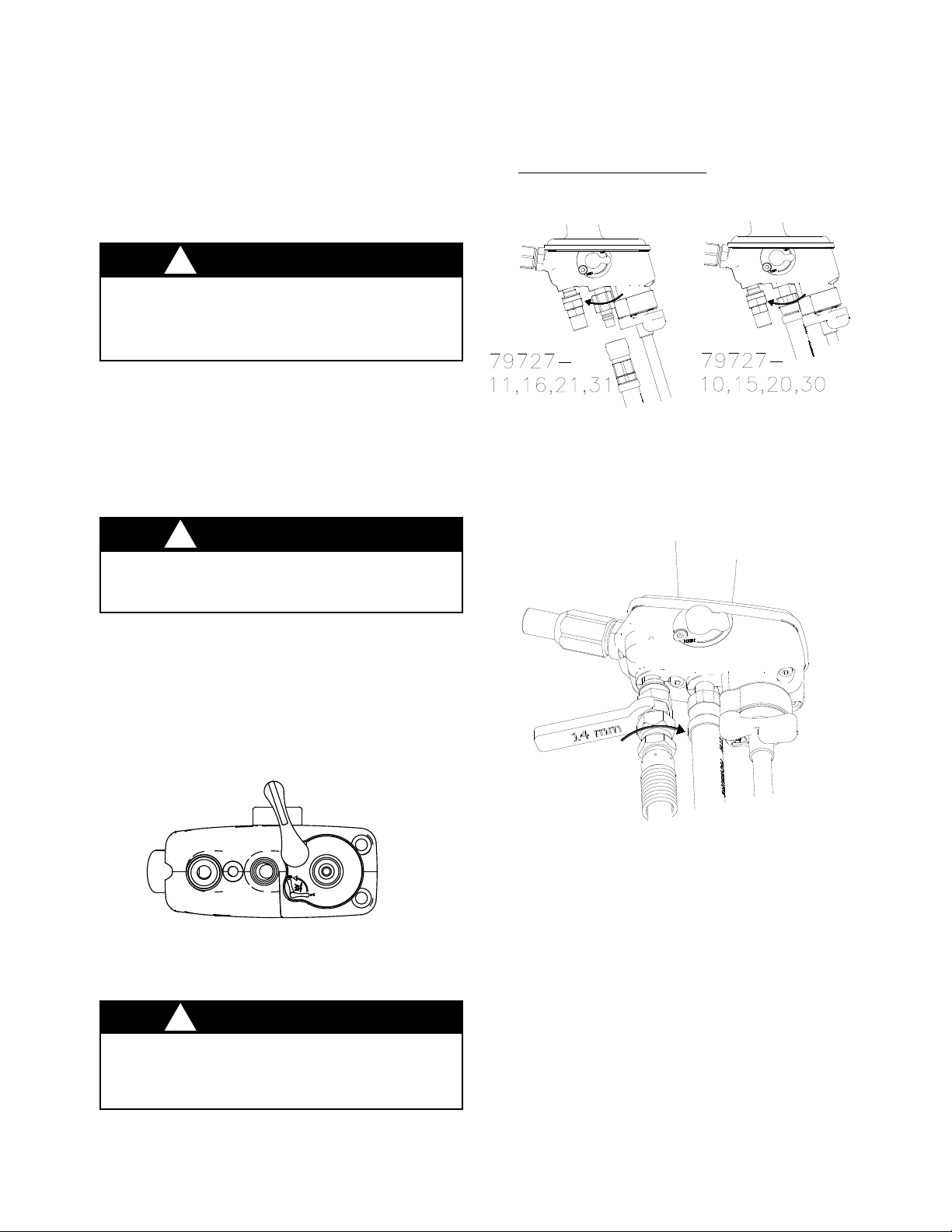
5. Connect the air hose or qd stem to the applicator, thread is left hand pitch, counter-clockwise
to tighten.
CCW
Figure 4: Air Hose Connection
6. Connect uid hose from grounded uid source
using a mwrench on the ats, tighten uid hose.
CCW
W A R N I N G
!
Both the uid source and the air hose
ground must be connected to true earth ground.
2. Connect the uid source to true earth ground.
3. Ensure electrostatic On/Off lever is in the Off
position.
4. Connect the air hose ground wire to true earth
ground.
Figure 3: Voltage Off Lever Position
(Bottom View)
CW
Figure 5: Fluid Hose Connection
7. Trigger the applicator with uid off. Look for
air leaks in any connections.
8. Activate uid, check for leaks with solvent.
if required. (See "Operation" section for
Flush
sequence.)
14
W A R N I N G
!
It is the end users responsibility to insure
the ground end of the 79727-XX air hose is
connected to true earth ground.
AH-08-04.2

Ransburg
F
VO
OPERATION
SAFE OPERATION
Vector Solo AA90 Applicators - Operation
• Ground all operators by requiring that they hold
the applicator handle with a bare hand.
• Ground operators and all other persons in spray
areas by requiring that they wear conductive
soled shoes or grounding straps.
• Have exhaust fans operating while spraying.
• Exhaust fans must be interlocked with the at-
omization air.
• See that no more than one gallon of solvent per
safety container per operator is inside of the
hazard location.
• If ANY symptom of improper operation occurs,
suspend use of the unit until the problem has
been diagnosed and corrected. See "Troubleshooting Guide" in the "Maintenance" section
or contact your authorized Ransburg representative.
• Ground MUST be maintained during the addi-
tion of uid to any supply container! Whenever
transferring ammable uid from one container
to another, both containers MUST be properly
connected to a proven ground rst and then to
each other. Personnel executing such a transfer
MUST also be grounded.
determine the chemical content of your solvents.
(See "HHC Explosion Hazard Danger Sign" and
"Halogenated Hydrocarbon Safety Bulletin".)
• Never ush the applicator with solvent while
electrostatics are on. Failure to turn off electro-
statics while ushing may cause an IGNITION
HAZARD. Applicator supply air must be inter-
locked with solvent supply.
1. Ensure the On/Off switch is in the desired position for voltage.
LTAGE ON
Figure 6: Voltage On/Off Position
2. Ensure the voltage high/low switch is in the
desired position.
VOLTAGE OF
• A chemical reaction resulting in the possibility
of a pressure EXPLOSION, may occur if 1,
1, 1-Trichloroethane, Methylene Chloride, or
other Halogenated Hydrocarbon solvents are
used in PRESSURIZABLE FLUID SYSTEMS
having ALUMINUM or GALVANIZED WETTED
PARTS. Such an explosion could cause DEATH,
serious BODILY INJURY and/or substantial
property damage. Consult your uid supplier to
AH-08-04.2
60% VOLT AGE
Figure 7: High/Low Voltage Selection
3. Open the uid supply - 207 bar (3000 psig )
maximum working pressure.
100% V OLTAGE
15

Vector Solo AA90 Applicators - Operation
Ransburg
TABLE I - PRESSURE AT
REGULATOR
1 - Fluid Supply
2 - Flow Regulator
Figure 8: Fluid Supply Pressure Adjustment
4. Increase air pressure to the applicator depend-
ing upon amount of air required to eliminate the
tails. Minimum pressure is 2.75 bar (40 psig) at the
handle. Use either gauge from Maintenance and
Test Kit or use Table I to use a gauge reading at
the wall regulator adjusted for the pressure drop
in the air hose.
79727
Hose Length
30m
20m
15m
10m
5. Adjust fan pattern size. Counter-clockwise
de
creases fan, clockwise increases fan pressure.
Full closed fan produces the lasgest pattern. Full
open fan produces the smallest fan pattern size.
Pressure At
Wall Regulator Gauge
3.8 bar (55 psig)
3.5 bar (50 psig)
3.3 bar (48 psig)
3.1 bar (45 psig)
16
Figure 10: Fan Pattern Size Adjustment
Figure 9: Air Pressure at Regulator
AH-08-04.2

Ransburg
Vector Solo AA90 Applicators - Operation
6. The AA90 Applicator incorporates a new feature,
that being a locating air cap. (Refer to Figure 11
for a view showing the locating pin.) This feature
gives the capability to spray with a fan pattern in
either horizontal or vertical positions.
7. Table I shows the available tip sizes. Table
II shows the available pre-orice sizes. The
pre-orice selected should be sized approximately
.025mm (.001-inch) at 65 bar (1000 psig) pressure
owing larger then the tip size opening. The
pre-orice use can signicantly increase useful
spray life of the tip.
TABLE I
NOZZLE SELECTION GUIDE
Nozzle
Identication
AA90 Fluid
Nozzle
Part #
79691-0509
79691-0511
79691-0513
79691-0811
79691-0813
79691-1009
79691-1011
79691-1013
79691-1015
79691-1018
79691-1021
79691-1311
79691-1313
79691-1315
79691-1318
79691-1511
79691-1513
79691-1515
79691-1518
79691-1521
79691-1715
Orice Size
in Inches
Operating
Parameters
Nozzle
(mm)
.009 (.23)
.011 (.28)
.013 (.33)
.011 (.28)
.013 (.33)
.009 (.23)
.011 (.28)
.013 (.33)
.015 (.38)
.018 (.46)
.021 (.53)
.011 (.28)
.013 (.33)
.015 (.38)
.018 (.46)
.011 (.28)
.013 (.33)
.015 (.38)
.018 (.46)
.021 (.53)
.015 (.38)
Pattern
Width at
10-in. (mm)
5-in (127)
8-in. (203)
10-in. (254)
13-in. (330)
15-in. (381)
17-in. (432)
AH-08-04.2
Figure 11: Air Cap Alignment Locating
Pin Position
Figure 12: Pre-Orice Seal Sizes Dash
Number Location
The rst two digits of the nozzle dash number
indicate the spray pattern width in inches at a
distance of 10- inches (254mm) from the target.
The second two digits indicate the orice size in
thousandths of inches.
For example: 79691-1015 has a 10-inches
(254mm) spray pattern width and an orice size
of 0.015-inches (.38mm).
17

Vector Solo AA90 Applicators - Operation
TABLE II - 79692-XX PRE-ORIFICE SEAL SIZES
Part # Restrictor Orice SizeMatching Spray Tip Part #
Ransburg
79692-01
79692-02
79692-03
79692-04
79692-06
79692-07
8. The applicator is shipped standard with a plug
in the atomization air port. If lower atomization
air pressures are desired, a compensation valve
is included with each applicator and can be used
instead of the plug. The compensation valve
(included seperate with applicator) reduces the
atomization air pressure approximately 0.2 bar
(3 psig) per clockwise turn from the wide open
position. To determine what pressure the applicator is set at, use the Air Cap Test Kit in the "Parts
Identication - Accessories" section.
79691-0509,-1009
79691-0511, -0811, -1011, -1311, -1511
79691-0513, -0813, -1013, -1313, -1513
79691-1015, -1315, -1515, -1715
79691-1018, -1318, -1518
79691-1021, -1521
.1010" (.256mm)
.1021" (.307mm)
.0141" (.358mm)
.0161" (.409mm)
.0201" (.511mm)
.0221" (.561mm)
FLUSHING / COLOR CHANGE PROCEDURE
1. Turn electrostatic lever to Off position.
Figure 13: Compensation Valve - Full
Open Position
Figure 14: Electrostatics Lever Off Position
2. Turn off supply air.
1 - Main Air Supply
2 - Closed Ball Valve
Figure 15: Applicator Supply Air - Off
18
AH-08-04.2

Ransburg
Vector Solo AA90 Applicators - Operation
W A R N I N G
!
Supply air to the applicator must be in-
terlocked with the solvent supply. Supply air
must be off to the applicator when solvent
supply is on.
3. Relieve any uid pressure, then discharge uid
into appropriate grounded metallic container.
Applicator to Target Distance
The distance between the applicator and the tar-
get inuences the appearance of the nal nish
of the object. If the applicator is held too close,
under 100mm (approximately 4-inches), runs and
sags with excessive "bounce-back" may occur. If
the applicator is held too far from the object, the
electrostatic attraction is decreased. Normally,
the best spacing between applicator and target is
in the 150mm to 300mm area (6-inch to 12-inch).
C A U T I O N
!
The object being coated is maintained
at ground potential. The applicator operator is also grounded, therefore, the operator
has as much attraction for the electrostatic
paint as the object. To prevent "wrap-back"
always keep the applicator nozzle closer to
the target than to the operator.
Figure 16: Applicator Flush Out
4. Load next color or remove applicator from
installation as required.
THE RIGHT TECHNIQUE
Following are some basic electrostatic spray techniques. Depending on the spray target, it may be
necessary to adjust the technique.
Spray Width Determination
The size of the object being coated is the determining factor in adjusting the spray pattern. The
larger the object, the larger the required pattern
width. This is accomplished by uid nozzle selection. Air adjustment is used to remove "tails"
from the spray pattern and adjust the pattern size.
NOTE
The degree of atomization is depen-
dent on the viscosity of the paint formula-
tion, the applied uid pressure, and nozzle
selection.
Overlap
For the best "hiding" and uniformity of lm thickness, the stroke overlap should be approximately
50%. There should be some overlap at edges
of the part to increase edge coverage. Overlap
requirements may vary widely with different paint
formulations and different compositions of objects
being coated.
Triggering
Applicator triggering (ON/OFF) depends largely
on the desired results (the amount of wrap-around
required, edge coating, etc.). If the front and back
of the object are being coated, proper applicator
technique can edge coat in some instances without
making a specic pass for that purpose. Triggering the applicator before the target is directly
in front of the applicator may cause heavy edge
build-up on the leading edge of the target due to
the electrostatic attraction.
AH-08-04.2
19

Vector Solo AA90 Applicators - Operation
PREPARATION
Paint
A selection of the proper paint mixture is essential
to electrostatic operation. Paint test equipment
may be obtained through your Ransburg representative. For further paint formulation and test
procedures, consult your Ransburg representative
and/or your paint supplier.
Fluid Nozzle
Because of the design of the AA90 applicators,
the uid nozzle precision is paramount to proper
function. Ransburg makes every effort to assure
that all production of this part will meet the critical
design standards necessary for all applications.
The selection of the best nozzle to apply a given
coating to a specic article with maximum efciency is not an exact science. Testing is usually
necessary and wide experience with many types
of coating applications helps. Your Ransburg
representative uses such experience and actual
laboratory testing when recommending a nozzle
for your application needs.
Ransburg
will assist the user in making their own nozzle
selection whenever it becomes necessary. Se-
lection should always be veried by actual tests
to determine optimum efciencies.
Refer to "Nozzle Selction Guide" in this section for
the choice of spray width and spray characteristics
appropriate to the size and type of target. The
maximum nozzle ow capacity depends on the
orice size, the uid pressure, the paint viscosity,
and the spraying temperature. Always remember,
for maximum paint economy any nozzle selected
should always be operated at the lowest uid
pressure, which will give good atomization and
the required ow rate.
C A U T I O N
!
Ransburg recommends the use of a uid
lter in addition to the lter in the applicator
uid line to reduce nozzle clogging.
However, if parts, paints, or conveyor speeds are
changed, a different nozzle may be required for
best results. The following discussion and guide
20
AH-08-04.2

Ransburg
MAINTENANCE
Vector Solo AA90 Applicators - Maintenance
SUITABLE SOLVENTS FOR CLEANING VECTOR SOLO APPLICATORS
When cleaning the applicator, a suitable solvent
for cleaning depends on the part(s) of the applicator to be cleaned and the material that needs
to be removed. Ransburg recommends that all
exterior cleaning be done with non-polar solvents
to prevent a conductive residue on critical components. We also understand that some of these
solvents do not always meet the cleaning needs
of some materials. If conductive polar solvents
are used to clean the applicator components, all
residue must be removed using a non-conductive
non-polar solvent (i.e. high ash Naphtha). If there
are any questions as to what solvents are best for
cleaning , contact your local Ransburg distributor
and/or your paint supplier.
The Vector applicator, air hoses, and uid hose
assemblies should not be submerged or soaked
in solvent. However, the outer surfaces of these
items can be wiped with a suitable cleaning solvent. The items that cannot be soaked are noted
throughout this manual. All electrical components
cannot be cleaned or soaked in any solvents.
W A R N I N G
!
The user MUST read and be familiar
with the safety instructions in this manual.
If compressed air is used in cleaning,
REMEMBER that high pressure air can be
dangerous and should NEVER be used
against the body. It can blind, deafen, and
may even penetrate the skin. If used for
cleaning equipment, the user should wear
safety glasses.
ALWAYS turn the on/off lever on the
power module off prior to cleaning and servicing the equipment.
Be SURE the power is Off and the sys-
tem is grounded before using solvent to
clean ANY equipment.
DO NOT operate a faulty applicator!
When using cleaning solvent, standard
health and safety precautions should apply.
Any solvent used to clean the uid pas-
sages must be discharged into a grounded
container. Use of ungrounded or plastic
containers may cause re or explosion.
AH-08-04.2
NOTE
Use a non-polar solvent wipe as the
nal cleaning sequence for cleaning all
parts.
Cleaning of the exterior surface of the
applicator should be done with non-polar
solvents. If cleaning requires the use of polar solvents, the applicator should be wiped
down with non-polar solvent prior to going
back into use. Using polar solvents will
leave a semi-conductive lm on the surface
of the applicator that will effect efciency
of the applicator and cause damage to the
components.
21

Vector Solo AA90 Applicators - Maintenance
Ransburg
ROUTINE SCHEDULE
Follow these maintenance steps to extend the
life of the applicator and ensure efcient opera-
tion:
Several Times Daily
• Inspect the air cap for paint accumulation.
Clean as frequently as necessary with a soft
bristled brush and a suitable solvent.
C A U T I O N
!
NEVER remove the uid nozzle assem-
bly while paint is in the applicator or paint
may enter into the air passages. Clogged or
restricted air passages will cause poor atomization and/or electrical shorting. Air passages that are clogged with conductive material
can lead to excessive current output levels
and consequent low operating voltage or
long-term electrical damage. Before undertaking any atomizer maintenance procedure.
Daily (or at start of each shift)
• Verify that ALL solvent safety containers are
grounded!
• Check within 6m (20-ft.) of the point of opera tion (of the applicator) and remove or ground
ALL loose or ungrounded objects.
• Inspect work holders for accumulated coat ing materials (and remove such accumula tions).
• Check that atomizer assembly is clean and
undamaged.
NOTE
Standard electrode is "snap back"
spray wire electrode.
•
Straighten the applicator electrode if necessary.
The applicator barrel MUST be tilted front down
to remove the uid nozzle. Failure to do so may
allow paint to enter the air passages, thereby
reducing airow and damaging the applicator
barrel/cascade. Applicators may be ushed
in lieu of tilting. However, they must be either
ushed or tilted down during nozzle removal!
• Clean all insulating surfaces in the system.
Remove paint accumulation from the exterior
of the applicator with a solvent dampened
cloth.
C A U T I O N
!
NEVER soak or submerge the electrical
components of the applicator, i.e., barrel,
power module, or handle. Damage and failure may occur.
• Clean the uid lter, if used.
Electrical Output Test
1. Turn the paint and/or solvent supply OFF.
W A R N I N G
!
Paint and/or solvent supply must be turned
off during this test-risk of re or explosion.
Flush the applicator (see "Flushing Proc
2.
in the "Operation" section).
3.
Follow instructions for use of the 76634-00 meter.
edure"
22
AH-08-04.2

Ransburg
Vector Solo AA90 Applicators - Maintenance
4. Using the meter set to kV, measure the output
voltage of the applicator. Voltage output reading
is between 67 and 75kV.
1 - Full Voltage Setting
2 - 76667-00 kV Probe
3 - 76634-00 Meter
Figure 17: kV Probe
5. See "Troubleshooting" in the "Maintenance"
section for possible cause of poor performance.
NOTE
There is a 10 giga ohm resistor in the
probe that lowers the output voltage. The
maximum kV rating is at no load. Paint
overspray and other contaminates on the
barrel will lower the kV probe reading.
APPLICATOR REPAIR
C A U T I O N
!
DO NOT allow the uid lines to stand
empty without ushing rst! This will cause
dried paint aking and clogging of the uid
lines, applicator passages, and/or nozzles.
All repairs should be made on a clean, at surface. If a vise is used to hold parts during service
or repair, DO NOT clamp onto plastic parts and
always pad the vise jaws!
The following parts should be thoroughly packed
with dielectric grease (LSCH0009-00) leaving NO
air space or voids when assembling:
• All O-Rings (Teon o-rings do not need
lubrication)
• Needle Shaft Assembly
• Packing Tube
• Cascade and Barrel
Equipment Required
• Special Multi-Purpose Wrench (79854-00) *
• 4mm, 3mm, and 2.5mm Allen Wrenches *
• Screwdriver (blade)
• Jam Nut Removal Tool (79793-00) *
• Dielectric Grease (LSCH0009-00) *
• Sealant, Medium Strength (7969-10)
• Dowel, 6mm (1/4") diameter
• Air Cap Removal Tool (79642-00) *
• 2.5mm Wrenches (two) (74133-00) *
• Nozzle Wrench (76428-00) *
AH-08-04.2
Note: *Supplied with applicator
23

Vector Solo AA90 Applicators - Maintenance
Ransburg
FLUSHING PROCEDURES
The uid system should be thoroughly cleaned by
ushing with a clean compatible solvent whenever
a color change is made, or when the applicator
will not be used for an extended period.
1. Turn OFF the control unit/power supply power.
2. Turn the paint supply OFF.
3. Turn the shaping air supply OFF. Bleed all air
from the line.
4. Tilt the applicator down and trigger until it is
clear of paint.
5. Set the trigger stop lever and remove the nozzle
nut, air nozzle, and uid nozzle.
6. Connect the solvent supply.
7. Release the trigger stop and run solvent through
the system until it runs clear.
C A U T I O N
!
If the coating material is fast settling and
the uid lines are not ushed soon enough,
the internal passages may become clogged.
This can lead to excessive downtime for repair.
Weekly
• Check the entire system for damage, leaks,
and paint accumulation.
• Clean the atomizer assembly.
APPLICATOR ASSEMBLY CLEANING PROCEDURE
Routine Cleaning
Equipment Needed
• An appropriate solvent
• Solvent safety container (grounded)
• Small soft-bristled brush
8. Disconnect the solvent supply.
9. Trigger the applicator until it is clear of solvent. After the preceding steps are complete, the
applicator is ready for color change, storage, or
maintenance.
NOTE
If production downtime is to be short,
the uid lines may not require ushing
(depending on the coating material being
used). If the solids in the coating settle
slowly, the lines will not need to be ushed
as soon after shutdown as with fast settling solids. The paint being used and the
length of downtime will determine the need
for ushing. Metallic paint and primer will
require ushing sooner than other types of
coating material.
For efcient electrostatic operation, keep the applicator’s exterior and low voltage/high voltage cable
free of paint accumulation. This prevents the loss
of voltage to ground with a resultant reduction in
transfer efciency.
C A U T I O N
!
Before cleaning the nozzle assembly,
turn the control unit or power supply OFF
and ush the uid line with a compatible solvent until clean. Turn the paint and air supplies OFF. Trigger the applicator to relieve
both uid and air pressures.
24
AH-08-04.2

Ransburg
Vector Solo AA90 Applicators - Maintenance
W A R N I N G
!
Ensure supply pressures have been
bled to zero prior to servicing the applicator.
Failure to do so may cause personal injury.
If the uid nozzle is completely clogged,
triggering the applicator will not release the
pressure. Cover the end of the applicator
with a heavy rag and loosen the nozzle nut
slowly into a grounded catch container.
Any broken or damaged components
should be replaced. Any damage to the
applicator may result in UNSAFE operating
conditions.
1. Turn the paint and air supplies OFF. Relieve
both uid and air pressures. Set the trigger stop
lever.
2. Unscrew the air cap retaining ring completely
from the barrel.
C A U T I O N
!
A wire brush or metal tools must NEVER
be used. NEVER use a cleaning tool that
is harder than the plastic parts. If a deposit
cannot be removed with solvent and a rag or
the soft brush, soak the part in solvent ONLY
until the deposit can be removed! NEVER
soak the applicator body, barrel, or hook
transformer!
W A R N I N G
!
NEVER wrap the applicator, associat-
ed valves and tubing, and supporting hardware in plastic to keep it clean. A surface
charge may build up on the plastic surface
and discharge to the nearest grounded ob-
ject. Efciency of the applicator will also be
reduced and damage or failure of the applicator components may occur. WRAPPING
THE
APPLICATOR IN PLASTIC WILL VOID
WARRANTY
.
3. With the front of the barrel tilted downward,
remove the air cap and uid nozzles.
4. Clean all parts in a suitable solvent and examine
for wear and damage. To clear the uid nozzle
orice, blow compressed air through the tip in the
opposite direction of ow. Soaking in solvent and/
or brushing may also be necessary to clean the
orice. Replace as necessary.
5. Clean all exterior surfaces of the applicator
with a rag and a suitable solvent.
6. Assemble the parts in reverse order of disassembly.
1. Remove applicator from the worksite after following the "Flush Procedure".
W A R N I N G
!
Ensure all pressure have been bled from
the uid and air line prior to disconnection.
AH-08-04.2
25

Vector Solo AA90 Applicators - Maintenance
CW
Ransburg
2. Remove uid hose at base of applicator.
CCW
Figure 18: Counter-Clockwise to
Remove Fluid Hose
3. Remove air hose at base of applicator.
CW
Spray Tip Removal/Carbide
Removal
1. Remove the retaining nut completely by hand.
2. Remove the air cap from applicator by grabbing
the horns pushing side to side while pulling the
cap away from the applictor.
Figure 20: Spray Tip Removal/Carbide Removal
3. Push the spray tip and holder out of the air cap
by pressing with a nger or soft object on the carbide or tapered portion of spray tip. The carbide
spray tip contains a removable nozzle seal with
or without a pre-orice. The pre-orice seal is
black, the standard seal is white. To remove the
sealfrom the tip holder, hold the end of the tip and
the end of the seal and snap apart the two pieces.
26
CW
Figure 21: Spray Tip and Seal Removal
Figure 19: Clockwise to Remove QD
Stem/Air Hose
AH-08-04.2

Ransburg
Vector Solo AA90 Applicators - Maintenance
4. By hand push the seal into the tip holder as
shown. The seal will be held in place in the holder.
Then place the tip holder on the insertion tool.
Hold the tip upright, align the pin in the cap to the
slot in the tip holder and push together. The tip
should snap in place in the air cap.
Figure 22: Seal Install/Carbide
Tip Holder Install
2. Remove two (2) screws with a 3mm Allen wrench
that hold the rear cover. Remove rear cover and
disconnect the connector.
3. Remove the rear uid adjustment bushing and
air valve and uid needle return springs.
Figure 24: Fluid Adjust Bushing Removal
BARREL REMOVAL
1. Remove air cap and uid nozzle.
4. Remove the trigger and uid line.
CCW
CCW
Figure 25: Fluid Line/Trigger Removal
AH-08-04.2
Figure 23: Rear Cover Removal
27

Vector Solo AA90 Applicators - Maintenance
Ransburg
5. Remove the two (2) jam nuts using the 7979300 Removal Tool while holding the needle shaft
with the 79793-00 Special Wrench.
Figure 26: Jam Nut Removal
6. Remove three (3) 5mm screws using a 4mm
Allen wrench. Remove the hook.
7. Pull the barrel straight away from the handle.
Figure 28: Barrel Removal
8. Using 79676 wrench, remove nozzle and gasket.
When removing, be sure to keep the drive teeth
of the tool engaged in the slots of the nozzle.
28
Figure 29: Fluid Nozzle and Gasket Removal
Figure 27: Barrel Screw Removal
AH-08-04.2

Ransburg
Vector Solo AA90 Applicators - Maintenance
Remove Cascade
1. Pull the cascade out of the barrel.
Figure 30: Cascade Removal
2. Wipe off excess dielectric lubricant.
3. Remove excess lubricant from inside barrel
with a clean cloth or rag.
Replace Cascade
Reinstalling Barrel
1. Replace the hook. Install the barrel against
the handle and hand tighten two (2) long 5mm
screws, in an alternating sequence with the 4mm
Allen wrench. Tighten the hook screw with the
same 4mm wrench.
1. Dispense about 1/4 tube of LSCH0009-00
inside the barrel and on the sides of the cascade.
C A U T I O N
!
Failure to use the LSCH0009-00 may
shorten product life.
Figure 31: Cascade Replacement
2. Slide the cascade back into the barrel.
Figure 32: Installing Barrel to Handle
2. Install the rst jam nut. Tighten to stop by hand
while holding the needle shaft.
1 - 79793-00 Removal Tool
2 - 1st Jam Nut
3 - 79854-00 Special Wrench
4 - 2nd Jam Nut (Raised Center)
Figure 33: First Jam Nut Replacement
AH-08-04.2
29

Vector Solo AA90 Applicators - Maintenance
Ransburg
3. Tighten second jam nut with raised center facing
out, while holding the needle shaft.
Figure 34: Second Jam Nut Replacement
4. Install the uid adjustment assembly along with
the air and uid return springs.
5. Install trigger and uid line.
CW
CW
Figure 36: Fluid Line/Trigger Installation
6. Reconnect the rear cover and install with two
(2) 4mm screws.
30
1 - Fluid Return Spring
2 - Air Valve Knob
3 - Air Valve Return Spring
Figure 35: Spring and Fluid Adjust
Valve Replacement
Figure 37: Rear Cover Replacement
AH-08-04.2

Ransburg
NEEDLE SHAFT REMOVAL/REPLACMENT
Vector Solo AA90 Applicators - Maintenance
1. Remove barrel from the handle using previous
steps.
2. Remove cascade.
Figure 38: Cascade Removal
3. Remove rear nut using the 79854-00 Special
Wrench.
5. Clean cavity with non-metallic brush and
non-polar solvent.
6. Replace needle components as required. (See
"Needle Shaft Parts List" in the "Parts Identication"
section for breakdown.)
Needle Shaft Packing
Replacement
1. Pull all rear seal parts off shaft. Replace
components as required.
Figure 39: Needle Shaft Removal
4. Attach a jam nut to the assembly and pull straight
out of the barrel.
Figure 40: Needle Shaft Removal
Figure 41: Needle Shaft Packing Replacement
2. Using two (2)74133 tools, remove carbide ball
and jam nut. Remove packing components.
Figure 42: Needle Shaft Packing Replacement
AH-08-04.2
31

Vector Solo AA90 Applicators - Maintenance
Ransburg
3. Remove front spreader seal, front u-cup seal,
rear spreader seal, rear u-cup seal, and pusher
seal.
Figure 43: Needle Shaft Packing Replacement
Needle Shaft Pack Reassembly
1. Install pusher seal, rear u-cup, rear spreader
seal, front u-cup seal, front spreader seal as shown.
Orient seals per Figures 41 and 43.
2. Install jam nut all the way on the shaft. Install
the carbide ball all the way down using two 74133
tools. Tighten the jam nut against the carbide ball.
Needle Shaft Rebuild
1. Prior to installing the needle shaft, partially ll
the internal bore of barrel with dielectric grease.
2. Fill the inner diameter of the packing tube with
dielectric grease.
3. Insert the needle shaft, rear section rst, into
the packing tube. Rotate the needle shaft while
moving back and forth inside the packing tube
until fully inserted.
4. With your nger, wipe the excess grease from
both ends of the packing tube. Using the excess
grease, apply a thin lm to the outer surface of
the packing tube and to the external o-ring on the
cartridge seal.
NOTE
Be generous with the dielectric grease
when applying it to the packing tube and
needle shaft. This helps to remove air
voids from this chamber. DO NOT apply
so much grease that it creates an air lock
during assembly of the applicator.
Figure 44: Needle Shaft Packing Reassembly
5. Apply a light lm of dielectric grease to the seal
retainer o-ring and install it into the external groove.
Reinstall Needle Shaft/Barrel
1. Push needle shaft assembly straight into the
barrel. Apply LSCH0009-00.
Figure 45: Needle Shaft Replacement
32
AH-08-04.2

Ransburg
Vector Solo AA90 Applicators - Maintenance
2. Tighten rear nut using Special Wrench 79854-
00. Tighten until drag is felt on the shaft when it
is pushed back and forth.
Figure 46: Adjustable Needle Shaft
3. Reinstall cascade.
4. Reinstall barrel to handle.
2. Remove three (3) bolts using a 3mm Allen
wrench.
Figure 48: Power Module Removal
3. Pull the module straight off the handle.
Power Module Removal
1. Remove the uid line.
CCW
CCW
Figure 47: Fluid Line Removal
Figure 49: Power Module Removal
NOTE
The power modules are not serviceable.
AH-08-04.2
33

Vector Solo AA90 Applicators - Maintenance
Ransburg
Handle Disassembly
1. Remove barrel.
2. Remove power module.
3. Push air valve out.
1 - Push Out From Here
Figure 50: Air Valve Removal
4. Remove the rear seal.
6. Remove air valve cartridge seal (black) (see
Figure 48).
7. Remove front air valve seal (white).
1 - Rear Seal
2 - Air Valve Cartridge Seal
3 - Front Air Valve Seal
34
Figure 51: Rear Seal Removal
5. Using a dowel rod, push out the air valve
cartridge.
1 - 6mm (1/4") Dowel
Figure 52: Air Valve Cartridge Removal
Figure 53: Air Valve Cartridge Seal and Front
Seal Removal
NOTE
If you remove the air valve seal, it is
highly recommended that it is replaced.
AH-08-04.2

Ransburg
Vector Solo AA90 Applicators - Maintenance
Handle Rebuild
1. Install the front air valve seal using the Special
Tool.
Figure 54: Air Valve Seal Replacement
2. Install the air valve cartridge seal.
3. Install the air valve cartridge. Align the cartridge
with tab at 12 o'clock posiition.
Figure 56: Air Valve Cartridge Alignment
4. Install the rear seal.
AH-08-04.2
Figure 57: Rear Cartridge Seal Replacement
5. Install air valve.
1 - 79793-00 Jam Nut Tool
2 - Front Air Valve Seal - Concave Side to Tool
Figure 55: Cartridge Seal Replacement
Figure 58: Air Valve Replacement
6. Reinstall barrel.
7. Install power module.
35

Vector Solo AA90 Applicators - Maintenance
Ransburg
Power Module - Fluid Fitting
Removal
1. Remove swivel from the power module and
the power module from thehandle.
CCW
Figure 59: Power Module Removal
3. Remove the 1/4 module from the 3/4 module.
Pull the uid tting out.
Figure 61: Fluid Fitting Removal
Fitting Replacement
1. Ensure the ground clip is properly installed.
Tabs must be touching the air and uid tting.
2. Remove two (2) screws using a 2.5mm Allen
wrench.
Figure 60: Fluid Fitting Removal
Figure 62: Ground Clip Replacement
W A R N I N G
!
The ground clip must be properly in-
stalled such that it touches both the air and
uid tting.
36
AH-08-04.2

Ransburg
Vector Solo AA90 Applicators - Maintenance
2. Install the uid tting.
Figure 63: Fluid Fitting Replacement
3. Install the 1/4 module into the 3/4 module and
tighten the two (2) screws.
Figure 64: Module Assembly
TEST AND MAINTENANCE KIT USAGE (79870-00)
6
5
3
1
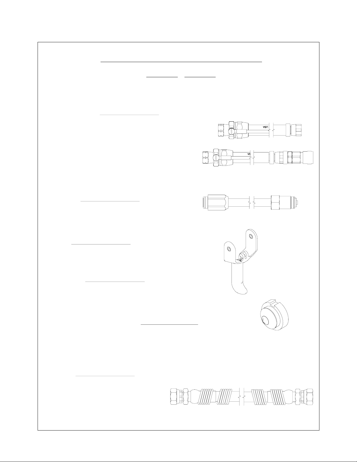
Figure 66: 79870 Test and Maintenance Kit
79870 TEST AND
MAINTENANCE KIT
Item#
1
2
3
4
5
6
Brass Tee Fitting
100 psi Pressure Gauge
6" Air Hose Assembly
Left Hand Male Fitting
Barb Fitting
Tubing
Description
2
4
4. Install power module to handle and tighten
three (3) screws. Reinstall the uid line.
CW
Figure 65: Power Module Assembly
AH-08-04.2
The 79870 Test and Maintenance Kit allows the
user to determine the inlet pressure at the base
(handle) of the Vector Solo hand-held applicators.
The Test and Maintenance Kit also allows the user
to test the 79835 Power Module Assembly on the
Vector Solo applicator.
The procedure to test the inlet pressure at the
base (handle) of the Vector Solo applicator is as
follows (see Figures 66 and 67):
1. Connect the left-hand tting of the 79727 Air
Hose to the male inlet of the Test and Maintenance
Kit.
2. Connect the 6" air hose assembly between the
brass tee tting and the gun air inlet.
37

Vector Solo AA90 Applicators - Maintenance
Ransburg
3. Connect the other end of the air hose to the
regulated air supply.
4. Turn on main air. Trigger the applicator with kV
switch on high (down position). Read the pressure
at the 100 psi pressure gauge. This pressure
should be at least 40 psi with air owing for proper
functioning of the Vector Solo AA90 applicator.
2. Connect the barb tting [5] to the brass tee
tting [1]. Place the tubing [6] on the end of the
barb tting.
6
5
Figure 69: Connect Barb and Tubing to
Tee Fitting
1
LH
3. Connect the left-hand tting of the 79727 Air
Hose to the male inlet of the Test and Maintenance
Kit.
Figure 67: Testing the Pressure
at the Base (Handle)
of the Applicator
The procedure to test the 79835 Power Module
Assembly is as follows:
1. Remove the 79835 Power Module Assembly
from the handle.
4. Insert the tubing [6] into the smaller diameter
hole in the top of the air tting in the power module.
6
Figure 70: Connect Tubing to the Air Fitting
38
Figure 68: Remove Power Module from Handle
AH-08-04.2

Ransburg
TP-1
TP-1
3. Connect the left-hand tting of the 79727 Air
Hose to the male inlet of the Test and Maintenance
Kit.
4. Insert the tubing [6] into the smaller diameter
hole in the top of the air tting in the power module.
5. Connect a wire from test point 2 (on the PC
board in the power module) to a true earth ground.
6. Connect a digital multi-meter to test points 1
and 2.
TP-1-Test Point #1
TP-2-Test Point #2
Ground-True Earth
Vector Solo AA90 Applicators - Maintenance
TP-2
1.7 BAR
(25 PSIG)
Figure 72: Set Pressure Gauge to
1.7 BAR (25 psig)
TP-2
Figure 71: Connect the PC Board to a Digital
Multi-Meter and True Earth Ground
7. Connect the 79727 Air Hose to main air.
8. Turn on main air and set the pressure so the
pressure gauge [2] in the 79870 Test and Maintenance Kit reads 25 psi (1.7 bar). The voltage
kV setpoint lever should be in the high voltage
position (down). The digital multi-meter should
read approximately 15 VDC.
9. If the voltage is outside this range, there is a
problem with the power module circuitry. If the
voltage range is acceptable the power module is
operating correctly, and there is an issue with either
the cascade or the wire connections leading to it.
Air Hose -Ground Wire End
1. Cut the end of the air hose so that end is square.
2. Slide the sleeve and compression ring onto the
air hose end.
Figure 73: Sleeve and Compression Ring
3. Push the stem of the tting all the way into the
into the air hose.
Figure 74: Ground Fitting Insertion
AH-08-04.2
39

Vector Solo AA90 Applicators - Maintenance
4. Slide the compression ring and the sleeve into
the tting body and tighten.
Figure 75: Sleeve Tightening
Air Hose -Applicator End
1. Cut the end of the air hose so that end is square.
Ransburg
0.8mm (1/32")
Figure 77: Tightening 79930 Fitting
2. Install the 79930 tting (std) or 79868 (qd)
into the hose end. Lightly lubricate the barb end
of the tting with LSCH-0009 di-electric lubricant.
Push the tting into the air hose up to the threads
on the stem.
Figure 76: Fitting Insertion
3. With the 79330 tting, hold the hose in one hand
and press a 6mm or 1/4" t-handle allen wrench
into the hex in the part while turning clockwise.
Tighten till cap is approximately .8 mm (1/32")
from the swivel nut.
0.8mm (1/32")
Figure 78: Tightening 79868 QD Fitting
Resistance Test
1. If the hose is changed, the resistance must
be checked. Using a Meg Ohm meter at 1000V
measure the resistance from the lug of the ground
wire to the body of the QD (79868) or the swivel
nut (79930). The reading must be less than .5
Mega Ohms resistance end to end.
4. With the 79868 DQ tting, hold the hose in one
hand and press against a rm surface while turning
the body wrench at clockwise. Tighten till cap is
approximately .8 mm (1/32") from the QD base.
40
Figure 79: Air Hose Resistance Test
AH-08-04.2

Ransburg
Vector Solo AA90 Applicators - Maintenance
TROUBLESHOOTING GUIDE
General Problem Possible Cause Solution
ELECTRICAL
No kV
Low kV
On-Off lever in wrong position
Low pressure
No ground connection
Cascade not functioning
Three (3) screws at base of handle
are loose
Failed power module
Fluid remnants in the air passage
Wrong solvent used for nal cleaning
process
Add sufcient air pressure at handle
Ensure the On/Off lever is in the
On position.
Ensure 40 psig (2.75 bar) at the applicator
handle with applicator triggered.
Ensure the air hose is properly grounded
to the earth ground.
Ensure cascade is functioning properly.
Tighten screws to ensure proper
assembly.
Ensure module is properly functioning.
Clean air passages with non-polar
solvent.
Use non-polar solvent for the nal
cleaning process.
Ensure 2.8 bar (40 psig) at the handle
with applicator triggered.
Poor Atomization
and Distribution
(Continued On Next Page)
AH-08-04.2
Partially clogged nozzle
Low uid pressure
Viscosity too high
Improper nozzle
Badly worn nozzle
High voltage electrode bend
Low shaping air pressure
Clean out.
Increase pump air pressure.
Try nozzle with narrower fan or smaller
orice.
Try nozzle with narrower fan or smaller
orice.
Thin the material to a viscosity that is
sprayable.
Straighten electrode or replace nozzle
assembly.
Re-adjust shaping air pressure.
41

Vector Solo AA90 Applicators - Maintenance
TROUBLESHOOTING GUIDE (Cont.)
General Problem Possible Cause Solution
ELECTRICAL
Ransburg
Poor Wraparound
Paint Wraps Back
On Operator
No Paint Delivery
Poor atomization
Excessive exhaust velocity
Excessive uid pressure
Applicator held too close to target
Paint too conductive
Poor target ground
Poor ground on parts
Applicator held too far from parts
Booth exhaust insufcient or improperly rounted
Improper spray technique
Clogged nozzle
See “Poor Atomization and Distribution”.
Reduce (with code limits).
Reduce air pressure to pump.
Hold applicator further back.
Consult Ransburg technical assistance.
Check ground integrity from target
through support to ground.
Check that parts are fully grounded,
strip workholders.
Hold applicator closer.
Increase, or adjust direction, change
booth lter.
Keep applicator directed at work.
Blow out nozzle.
Clogged hose or lters
No pressure at paint pump
Excessive Surging
Persistent Nozzle
Restriction in pump air line
Insufcient pump capacity
Clogged paint lter
Low air volume capacity
Nozzle too large
Paint allowed to dry in nozzle or line
Clogging
Paint applicator lter too coarse or
damaged
Paint pigments too coarse
(Continued On Next Page)
Clean.
If pump air supply OK, consult pump
manual.
Remove restriction.
Secure larger pump or reduce output.
Service or replace.
Check factory air capacity.
Replace with correct nozzle.
Flush lines with solvent after each use.
Replace or change to ner screen
paint lter.
Pre-lter paint and/or use larger
nozzle orice.
42
AH-08-04.2

Ransburg
Vector Solo AA90 Applicators - Maintenance
TROUBLESHOOTING GUIDE (Cont.)
General Problem Possible Cause Solution
ELECTRICAL
Paint Leaks
Through Center
of Nozzle
(Failure to Shut Off)
Paint Leaks
Around the
Nozzle Cap
Paint Leaks At
Rear of Barrel
Orange Peel or
Rough Finish
Paint Runs or
Has Poor Hiding
Qualities
Loose nozzle cap
Improper trigger adjustment
Defective or dirty valve seat
Loose nozzle cap
Fluid seal worn
Loose packing nut
Evaporation rate too fast
Poor atomization
Viscosity too high
Low solids paint
Low viscosity
Excessive delivery
Tighten nut.
Readjust.
Flush out or replace as needed.
Tighten nut.
Replace seal.
Tighten packing nut.
Use slower evaporating solvent.
See “Poor Atomization and Distribution”.
Add solvent or heat.
Use less solvent.
Use less solvent.
Use smaller nozzle, wider fan angle,
and lower pump pressure.
AH-08-04.2
43

Vector Solo AA90 Applicators - Parts Identication
PARTS IDENTIFICATION
79698 VECTOR SOLO AA90 APPLICATOR
MODEL IDENTIFICATION
When ordering, use 79698-A, B, C, D, and E as indicated by Tables A, B, C,
D, and E. Five digits must follow the basic part number, for example:
79698 - A B C D E
Ransburg
Basic Part Number
Air Hose Length
Fluid Inlet
(Table A)
Included-0
(Table E)
(Table D)
(Table C)
TABLE A - AIR HOSE LENGTH AND AIR HOSE TYPE
"A"
Dash #
1
2
3
4
5
6
7
8
Description
10m (33-ft.)
15m (49-ft.)
20m (66-ft.)
30m (99-ft.)
10m (33-ft.)
15m (49-ft.)
20m (66-ft.)
30m (99-ft.)
Standard Air Hose
Standard Air Hose
Standard Air Hose
Standard Air Hose
Air Hose W/Quick-Disconnect / QD Stem
Air Hose W/Quick-Disconnect / QD Stem
Air Hose W/Quick-Disconnect / QD Stem
Air Hose W/Quick-Disconnect / QD Stem
Description
Fluid Hose Length
Spray Tip Size
Trigger Type
"A"
Air H ose/Stem
79727-10 / ---------
79727-15 / ---------
79727-20 / ---------
79727-30 / ---------
79727-11/ 79869-00
79727-16 / 79869-00
79727-21/ 79869-00
79727-31/ 79869-00
44
AH-08-04.2

Ransburg
TABLE C - TRIGGER TYPE
Vector Solo AA90 Applicators - Parts Identication
NOTES
Dash
#
2 79694-00
Description
2-Finger Trigger
"C"
TABLE D - SPRAY TIP SIZE
Dash
#
0
1
2
3
Description
Carbide Tip Assembly
Carbide Tip Assembly
Carbide Tip Assembly
Carbide Tip Assembly
"D"
79691-0811
79691-0813
79691-1011
79691-1015
TABLE E - FLUID HOSE LENGTH
Dash
#
0
1
2
3
4
No Fluid Hose
11m (36-ft.) Pant Hose, 3/16" ID
15m (50-ft.) Paint Hose, 3/16" ID
23m (75-ft.) Paint Hose, 3/16" ID
30m (100-ft.) Paint Hose, 3/16" ID
Description
"E"
-7994-36
7994-50
7994-75
7994-100
AH-08-04.2
45

Vector Solo AA90 Applicators - Parts Identication
VECTOR SOLO AA90 SOLVENTBORNE APPLICATOR
Ransburg
13
1515
27
28
34
26
29
25
44
15
45
46
46
41
40
1616
39
19
30
43
20
14
42
37
38
23
36
21
31
22
57
7
35
18
18
17
12
50
6
32
11
48
47
51
52
5
2
4
1
10
53
49
54
56
8
3
9
33
22
Figure 80: Vector Solo AA90 Applicators Parts Breakdown
46
AH-08-04.2

Ransburg
Vector Solo AA90 Applicators - Parts Identication
VECTOR SOLO AA90 SOLVENTBORNE APPLICATOR PARTS LIST
(Figure 80)
Item #
1 79668-00 Assembly, Fluid Nozzle 1
2 72375-03 Seal, Teon 1
3 Table "D" Carbide Tip Assemblies 1
4 79692-00 Seal, No Pre-Orice 1
79692-00-K3 Kit of 3 (Optional, No Pre-Orice)
79692-01 Seal, .0101" (.256mm) Pre-Orice
79692-02 Seal, .0121" (.307mm) Pre-Orice
79692-03 Seal, .0141" (.358mm) Pre-Orice
79692-04 Seal, .0161" (.409mm) Pre-Orice
79692-05 Seal, .0201" (.511mm) Pre-Orice
79692-06 Seal, .0221" (.561mm) Pre-Orice
5 79689-00 Assembly, Vector Solo AA90 Barrel 1
6 79600-00 Cascade Assembly 1
7 79832-00 Gasket, Barrel 1
8 79695-00 Assembly, Air Cap, Vector Solo AA90 1
9 79568-00 Ring, Retaining, Air Assist 1
10 72375-02 Seal, Teon 1
11 79921-00 Assembly, Fluid Tube, Vector Solo AA90 1
12 7720-01 Filter, Paint (Standard, .005" Spacing, 100 Mesh) 1
7720-02 Filter, Paint (Optional, .009" Spacing, 60 Mesh)
13 79816-00 Assembly, Rear Cover 1
14 79798-03 Socket Head Cap Screw, M5 X 30 1
15 79799-01 Socket Head Cap Screw, M4 X 25 4
16 79798-02 Socket Head Cap Screw, M5 X 80 2
17 Table "C" Trigger, Modied, Vector Solo AA90 1
18 79454-00 Screw, Trigger Retention 2
19 79762-00 Nut, Fluid Jam 1
20 79701-00 Hook, Molded 1
21 79799-02 Socket Head Cap Screw, 4mm X 30mm Lg. 1
22 Table "A" Assembly, Air Hose 1
23 79833-04 Assembly, Handle Vector Solo AA90 1
(Includes Items 34, 35, 36, 37, 38, 39, 40, and 41)
24 79833-05 Assembly, Handle Only 1
25 79835-01 Assembly, Power Module 1
(Includes Items 42, 43, 44, and 45)
26 79666-00 Nut, Jam 1
27 78824-00 Spring 1
28 79673-00 Assembly, Air Valve Knob 1
29 79781-00 Seal, Adjustment Bushing 1
30 79837-00 Gasket, Power Module 1
31 79920-00 Swivel, High Pressure, Vector Solo AA90 1
32 79688-00 Assembly, Needle Shaft, Vector Solo AA90 1
33 79861-00 Tubing, Clear Tygothane Polyurethane, 1/4" ID X 3/8" OD 1
34 79774-00 Spring, Air Valve Return 1
35 79662-00 Trigger Lock 1
36 79602-00 Roll Pin 1
37 79760-00 Seal, Air Valve 1
38 79001-09 O-Ring, Solvent Proof 1
Part # Description Qty
(Continued On Next Page)
AH-08-04.2
47

Vector Solo AA90 Applicators - Parts Identication
VECTOR SOLO AA90 SOLVENTBORNE APPLICATOR PARTS LIST (Cont.) (Figure 80)
Ransburg
Item #
39 79770-00 Cartridge, Air Valve 1
40 79772-00 Assembly, Air Valve 1
41 79759-00 Assembly, Fan Air Adjust Valve 1
42 79847-00 Valve, Atom Adjust (Optional) 1
79847-01 Plug, Atom (Standard installed in applicator)
43 79881-00 Gasket, Exhaust, Wrap-Around 1
44 79836-00 Gasket, Exhaust 1
45 79843-00 Assembly, Exhaust Housing 1
46 79805-00 Screw 3
47 79793-00 Jam Nut Removal/Seal Install Tool 1
48 74133-00 Wrench, Needle Shaft 1
49 79529-00-K5 Applicator Cover 1
50 LSCH0009-00 Dielectric Grease 1
51 79642-00 Cap Removal Tool 1
52 79862-01, 02, -03 Hex Driver (2.5mm, 3mm, and 4mm) Wrench, 1
Vector Solo AA90
53 79854-00 (Packing Adjust, Barrel Removal, Nozzle Removal) 1
54 79676-00 Wrench, Nozzle Removal 1
55 Table "E" Fluid Hose (Not Shown) 1
56 LSOR0005-17 O-Ring, Teon Encapsulated 1
57 79869-00 Stem, Male QD (Included With QD Ordered Models) 1
Part # Description Qty
2
4
3
Figure 81: Power Module Replaceable Parts
3
5
1
POWER MODULE REPLACEABLE PARTS - PARTS LIST
(Figure 81)
Item #
1 79919-00 Fluid Inlet, AA 1
2 79746-00 Grounding Clip 1
3 79814-00 Socket Head Cap Screw, 4mm X 20mm Lg. 2
4 79637-00 1/4 Power Module -5 79636-00 3/4 Power Module --
Part # Description Qty
48
AH-08-04.2

Ransburg
Figure 82: Air Hose Assembly Parts
Vector Solo AA90 Applicators - Parts Identication
AIR HOSE ASSEMBLY - PARTS LIST (Figure 82)
Item #
1 79869-00 Stem, Quick Disconnect Air Fitting (1/2-20 LH) 1
2 79868-00 Assembly, Quick Disconnect Fitting 1
3 79930-00 Hose Fitting Assembly (1/2-20 LH) 1
4 79938-00 Assembly, Ground Fitting 1
Part #
Description
Figure 83: High Pressure Whip and Fitting
HIGH PRESSURE WHIP AND FITTING - PARTS LIST
(OPTIONAL)
(Figure 83)
Qty
AH-08-04.2
Item #
1 76104-00 High Pressure Whip Hose, 1m 1
2 71880-06 Nipple, Male Double 1
Part #
Description
Qty
49

Vector Solo AA90 Applicators - Parts Identication
ACCESSORIES
Figure 84: Needle Shaft Assembly
NEEDLE SHAFT ASSEMBLY - PARTS LIST (Figure 84)
Ransburg
Item #
1 73351-00 Nut, Jam 1
2 73346-00 Seal, Pusher 1
3 79618-00 Spreader, Seal, Machined 1
4 72378-01 Packing Tube 1
5 73347-00 Container, Rear Seal 1
6 74330-00 Seal, High Pressure 1
7 73348-00 Retainer, Rear Seal 1
8 72209-05 O-Ring, Metric 1
9 73354-00 Nut, Packing 1
10 73345-00 Seal, Front U-Cup 1
11 79670-00 Assembly, Needle, Solo AA 1
12 73350-00 Assembly, Ball Valve 1
Part # Description
Figure 85: Fluid Hose - Optional
Qty
50
FLUID HOSE - PARTS LIST (Figure 85)
Item #
7994-36 Fluid Hose Assembly 4.8 mm (3/16") ID, 11 m (33 ft.) long
7994-50 Fluid Hose Assembly 4.8 mm (3/16") ID, 14 m (50 ft.) long
7994-75 Fluid Hose Assembly 4.8 mm (3/16") ID, 23 m (75 ft.) long
7994-100 Fluid Hose Assembly 4.8 mm (3/16") ID, 30 m ( 100 ft.) long
Part #
Description
AH-08-04.2

Ransburg
Vector Solo AA90 Applicators - Parts Identication
TEST AND MAINTENANCE KIT (OPTIONAL)
Part # Description
(Figure 86)
Figure 86: Test and Maintenance Kit - Optional
79870-00 Test and Maintenance Kit
VECTOR SOLO AA90 APPLICATOR RECOMMENDED SPARE PARTS
Part # Description
79668-00 Fluid Nozzle 2
79697-00 Assembly, Barrel, Vector Solo AA90 1
79600-00 Cascade Assembly 1
79832-00 Gasket, Barrel 1
79001-09 O-Ring, Solvent Proof 2
79695-00 Air Cap, Vector Solo AA90 2
79568-00 Retaining Ring 1
LSOR0005-17 O-Ring, Teon Encapsulated 1
79694-00 Assembly, Trigger 1
79454-00 Screw, Trigger Retention 2
79768-00 Nut, Fluid Jam, Front 1
79744-00 Spring, Air Valve Return 1
79835-00 Assembly, Power Module (Includes Items 39, 40, 41, 42, and 43) 1
79768-00 Nut, Fluid Jam,Spring Guide 1
78824-00 Spring 1
79781-00 Seal, Adjustment Bushing 1
79837-00 Gasket, Handle to Power Module 1
79760-00 Seal, Air Valve 1
79847-00 Valve, Compensation Atomizing 1
79836-00 Gasket, Exhaust 1
79843-00 Assembly, Exhaust Housing 1
79529-00-K5 Applicator Cover 2
LSCH0009-00 Dielectric Grease 2
72375-02 Fluid Tube Seal 2
72375-03 Nozzle Seal 1
79662-00 Trigger Lock 1
79602-00 Roll Pin 1
(Quantities Per Applicator)
Qty
AH-08-04.2
51

Vector Solo AA90 Applicators - Warranty Policies
WARRANTY POLICIES
LIMITED WARRANTY
Ransburg
Ransburg will replace or repair without charge
any part and/or equipment that fails within the
specied time (see below) because of faulty workmanship or material, provided that the equipment
has been used and maintained in accordance with
Ransburg’s written safety and operating instructions, and has been used under normal operating
conditions. Normal wear items are excluded.
THE USE OF OTHER THAN RANSBURG APPROVED PARTS VOID ALL WARRANTIES.
SPARE PARTS: One hundred and eighty (180)
days from date of purchase, except for rebuilt
parts (any part number ending in “R”) for which
the warranty period is ninety (90) days.
EQUIPMENT: When purchased as a complete
unit, (i.e., guns, power supplies, control units, etc.),
is one (1) year from date of purchase. WRAPPING
THE APPLICATOR, ASSOCIATED VALVES AND
TUBING, AND SUPPORTING HARDWARE IN
PLASTIC, SHRINK-WRAP, OR ANY OTHER
NON-APPROVED COVERING, WILL VOID THIS
WARRANTY.
RANSBURG’S ONLY OBLIGATION UNDER
THIS WARRANTY IS TO REPLACE PARTS
THAT HAVE FAILED BECAUSE OF FAULTY
WORKMANSHIP OR MATERIALS. THERE ARE
NO IMPLIED WARRANTIES NOR WARRANTIES
OF EITHER MERCHANTABILITY OR FITNESS
FOR A PARTICULAR PURPOSE. RANSBURG
ASSUMES NO LIABILITY FOR INJURY, DAMAGE TO PROPERTY OR FOR CONSEQUENTIAL DAMAGES FOR LOSS OF GOODWILL OR
PRODUCTION OR INCOME, WHICH RESULT
FROM USE OR MISUSE OF THE EQUIPMENT
BY PURCHASER OR OTHERS.
EXCLUSIONS:
If, in Ransburg’s opinion the warranty item in
question, or other items damaged by this part
was improperly installed, operated or maintained,
Ransburg will assume no responsibility for repair or
replacement of the item or items. The purchaser,
therefore, will assume all responsibility for any
cost of repair or replacement and service related
costs if applicable.
52
AH-08-04.2

Ransburg
Vector Solo AA90 Applicators - Manual Changes
MANUAL CHANGE SUMMARY
This manual was published to supersede Service Manual AH-06-01.10
Vector Solo Applicators to make the following changes:
1. Updated manual due to nozzle thread change from 9050 Control Unit
to the 9060 Control Unit.
AH-08-04.2
53

Manufacturing
1910 North Wayne Street
Angola, Indiana 46703-9100
Telephone: 260-665-8800
Fax: 260-665-8516
Technical Service — Assistance
320 Philips Ave.
Toledo, Ohio 43612-1493
Telephone (toll free): 800-233-3366
Fax: 419-470-2233
Ransburg
Technical Support Representative will direct you to the appropriate
telephone number for ordering Spare Parts.
© 2013 Ransburg. All rights reserved.
Models and specications subject to change without notice.
Form No. AH-08-04.2
Litho in U.S.A.
2/13
 Loading...