

Ransburg
REA AUTOMATIC APPLICATORS
SERVICE MANUAL
AA-99-02.5
(Replaces AA-99-02.4)
April - 2013
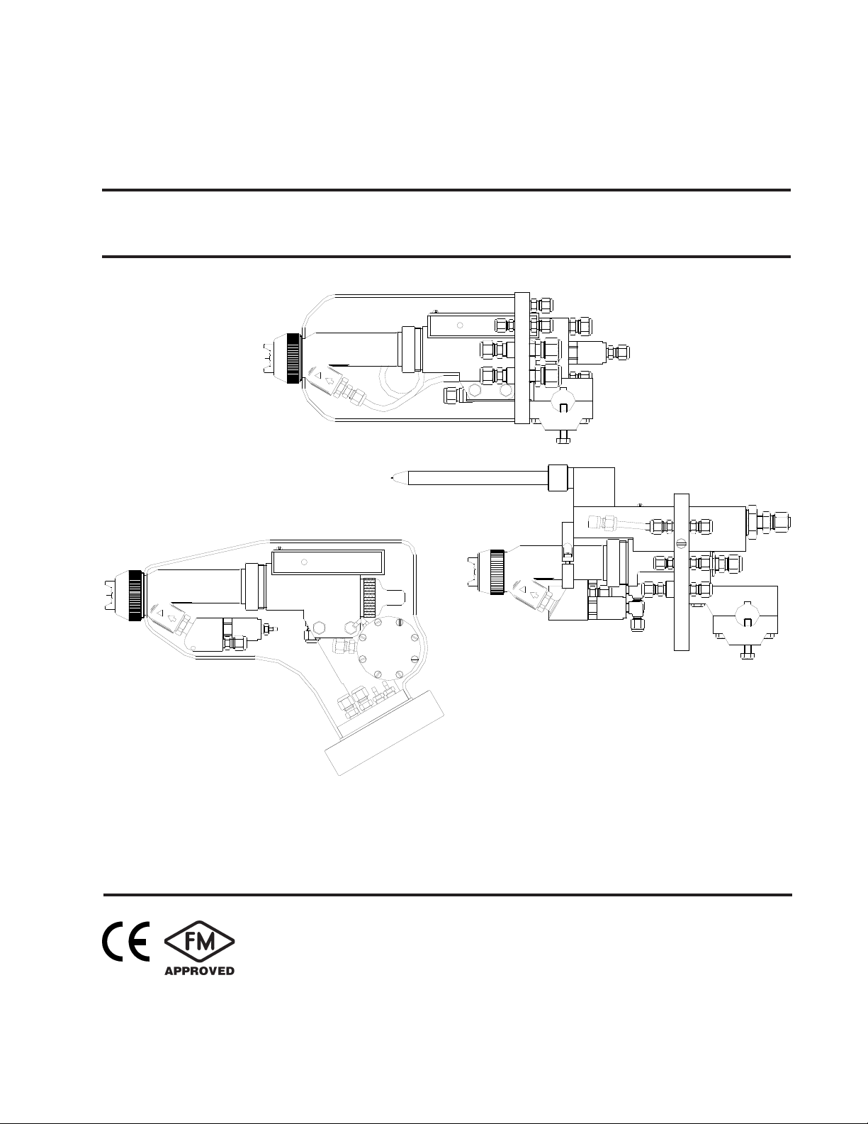
900A
9000W
(Not FM Approved)
9000R
MODELS: 77359 and 76110
77140 (Not FM Approved)
IMPORTANT: Before using this equipment,
carefully read SAFETY PRECAUTIONS, starting
on page 1, and all instructions in this manual.
Keep this Service Manual for future reference.
Service Manual Price: $50.00 (U.S.)

Ransburg
NOTE: This manual has been changed from revision AA-99-02.4 to revision AA-99-02.5.
Reasons for this change are noted under “Manual Change Summary” inside the back
cover of this manual.
REA Automatic Applicators
AA-99-02.5

REA Automatic Applicators - Contents
CONTENTS
SAFETY:
Ransburg
PAGE
1-5
SAFETY PRECAUTIONS..........................................................................................................
HAZARDS / SAFEGUARDS.....................................................................................................
ATEX
EUROPEAN ATEX DIRECTIVE.................................................................................................
EUROPEAN ATEX LABELS.......................................................................................................
INTRODUCTION:
DESCRIPTIONS.......................................................................................................................
SPECIFICATIONS
9000R...................................................................................................................................
9000W..................................................................................................................................
900A.....................................................................................................................................
INSTALLATION:
TYPICAL REA AUTOMATIC APPLICATOR INSTALLATION.................................................
ATOMIZER ASSEMBLY SELECTION TABLES......................................................................
MAINTENANCE:
ROUTINE SCHEDULE..............................................................................................................
ATOMIZER ASSEMBLY CLEANING PROCEDURE...............................................................
FLUSHING PROCEDURES......................................................................................................
TROUBLESHOOTING GUIDE.................................................................................................
SERVICE - REA 9000W SERIES:
EQUIPMENT REQUIRED.............................................................................................
REPLACEMENT PROCEDURE...................................................................................
TO REMOVE APPLICATOR FROM THE WORKSITE................................................
NOZZLE AND ELECTRODE CLEANING / REPLACEMENT.....................................
BARREL ASSEMBLY REMOVAL.................................................................................
BARREL DISASSEMBLY..............................................................................................
BARREL REASSEMBLY...............................................................................................
BARREL TO BODY ASSEMBLY..................................................................................
HIGH VOLTAGE MODULE ASSEMBLY REPLACEMENT (9000W Only).................
LOW VOLTAGE CABLE REPLACEMENT (900A Only)..............................................
VALVE BODY SERVICE...............................................................................................
AIR VALVE BODY DISASSEMBLY..............................................................................
RETURN THE SPRAY APPLICATOR TO THE WORK SITE.....................................
SERVICE - REA 9000R AND 900A SERIES:
BARREL ASSEMBLY REMOVAL.................................................................................
NOZZLE AND ELECTRODE CLEANING OR REPLACEMENT.................................
BARREL DISASSEMBLY..............................................................................................
BARREL REASSEMBLY...............................................................................................
(Continued On Next Page)
1
2-5
6-7
6
7
8-14
8-13
14
14
15
16-19
16-19
19
20-40
20-21
22
23
24-25
26
26
26
27-28
29
29
30
31
31
31-32
32
32
32
33
33-34
34-35
35-36
AA-99-02.5

Ransburg
Contents (Cont.)
REA Automatic Applicators - Contents
PAGE
MAINTENANCE (Cont.):
P-EXTENSION REMOVAL (REA 9000R Only) ...........................................................
P-EXTENSION REPLACEMENT (9000R Only) ..........................................................
AIR BUSHING / BODY DISASSEMBLY.......................................................................
AIR BUSHING / BODY ASSEMBLY.............................................................................
TRANSFORMER ASSEMBLY REPLACEMENT (REA 9000R AND 900A)............................
LOW VOLTAGE CABLE REPLACEMENT (9000R Only)........................................................
LOW VOLTAGE CABLE CONNECTOR ASSEMBLY (9000R Only).......................................
LOW VOLTAGE CABLE PLUG ASSEMBLY (9000R Only).....................................................
PARTS IDENTIFICATION:
REA 9000R SOLVENTBORNE ASSEMBLY............................................................................
REA 9000R REAR MOUNTING PLATE ASSEMBLY...............................................................
REA 9000R SOLVENTBORNE PARTS LIST...........................................................................
REA 9000R SPARE PARTS IN KIT / RECOMMENDED SPARE PARTS................................
REA 9000W WATERBORNE ASSEMBLY ...............................................................................
REA 9000W WATERBORNE PARTS LIST..............................................................................
REA 9000W SPARE PARTS IN KIT / RECOMMENDED SPARE PARTS................................
REA 900A SOLVENTBORNE ASSEMBLY...............................................................................
REA 900A SOLVENTBORNE PARTS LIST.............................................................................
REA 900A SPARE PARTS IN KIT / RECOMMENDED SPARE PARTS...................................
MISCELLANEOUS KITS............................................................................................................
20-40
36
36
37
37-38
39
39
39-40
40
41-60
41
42
43-45
46-47
48
49-51
51
52
53-55
56-57
58-59
WARRANTIY POLICIES:
LIMITED WARRANTY................................................................................................................
60
60
AA-99-02.5
REA Automatic Applicators - Safety
SAFETY
Ransburg
SAFETY PRECAUTIONS
Before operating, maintaining or servicing any
Ransburg electrostatic coating system, read and
understand all of the technical and safety literature for your Ransburg products. This manual
contains information that is important for you to
know and understand. This information relates to
USER SAFETY and PREVENTING EQUIPMENT
PROBLEMS. To help you recognize this information, we use the following symbols. Please pay
particular attention to these sections.
A WARNING! states information to alert you
to a situation that might cause serious injury
if instructions are not followed.
A CAUTION! states information that tells how
to prevent damage to equipment or how to
avoid a situation that might cause minor injury.
A NOTE is information relevant to the procedure in progress.
W A R N I N G
!
The user MUST read and be familiar with the
Safety Secon in this manual and the Ransburg
safety literature therein idened.
This manual MUST be read and thoroughly
understood by ALL personnel who operate, clean
or maintain this equipment! Special care should
be taken to ensure that the WARNINGS and
safety requirements for operang and servicing
the equipment are followed. The user should be
aware of and adhere to ALL local building and re
codes and ordinances as well as NFPA-33 SAFETY
STANDARD, LATEST EDITION, prior to installing,
operang, and/or servicing this equipment.
W A R N I N G
!
While this manual lists standard specications
and service procedures, some minor deviations
may be found between this literature and your
equipment. Differences in local codes and plant
requirements, material delivery requirements,
etc., make such variations inevitable. Compare
this manual with your system installation drawings and appropriate Ransburg equipment manuals to reconcile such differences.
Careful study and continued use of this manual will
provide a better understanding of the equipment
and process, resulting in more efcient operation,
longer trouble-free service and faster, easier
troubleshooting. If you do not have the manuals
and safety literature for your Ransburg system,
contact your local Ransburg representative or
Ransburg.
The hazards shown on the following pages
may occur during the normal use of this equipment. Please read the hazard chart beginning on
page 2.
1
AA-99-02.5

Ransburg
REA Automatic Applicators - Safety
AREA
Tells where hazards
may occur.
Spray Area
HAZARD
Tells what the hazard is.
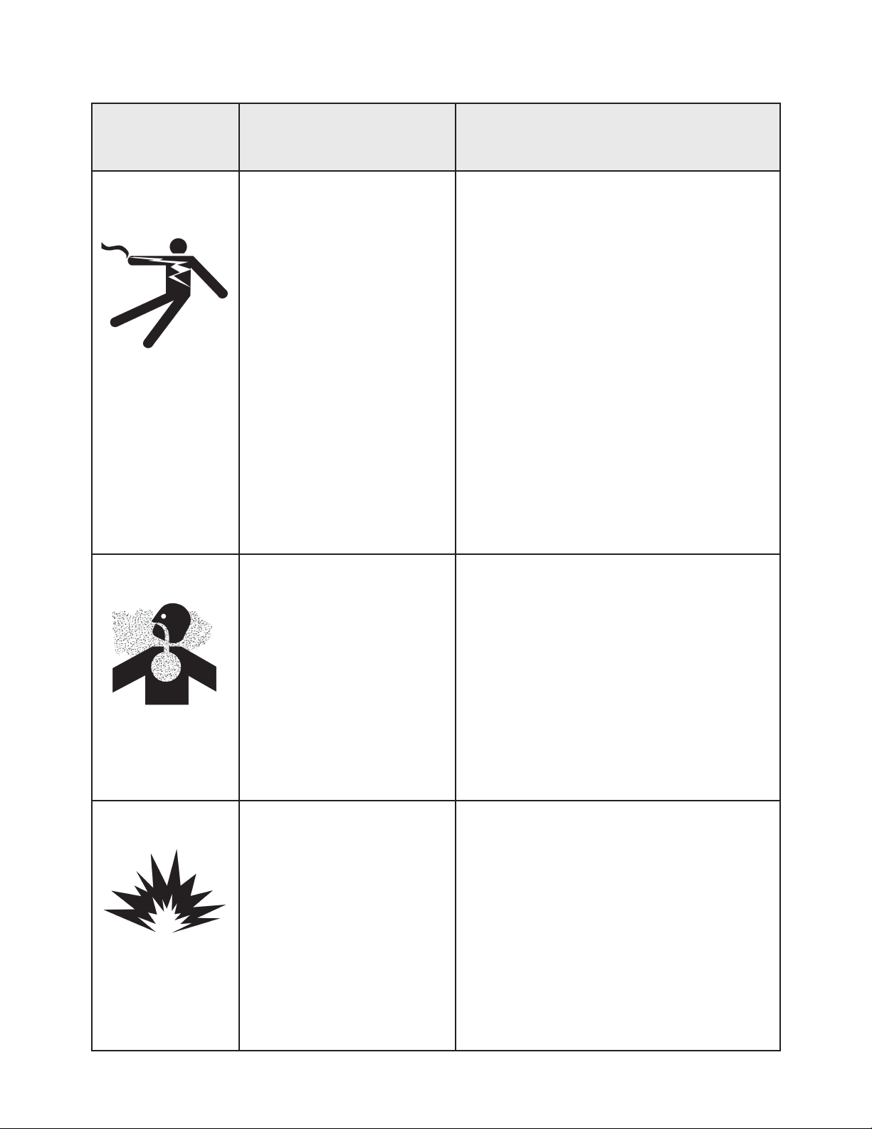
Fire Hazard
Improper or inadequate
operation and maintenance
procedures will cause a re
hazard.
Protection against inadvertent arcing that is capable of
causing re or explosion is
lost if any safety interlocks
are disabled during operation. Frequent Power Supply
or Controller shutdown indicates a problem in the system
requiring correction.
SAFEGUARDS
Tells how to avoid the hazard.
Fire extinguishing equipment must be present in
the spray area and tested periodically.
Spray areas must be kept clean to prevent the
accumulation of combustible residues.
Smoking must never be allowed in the spray
area.
The high voltage supplied to the atomizer must
be turned off prior to cleaning, ushing or maintenance.
When using solvents for cleaning:
• Those used for equipment ushing should
have ash points equal to or higher than
those of the coating material.
• Those used for general cleaning must have
ash points above 100°F (37.8°C).
Spray booth ventilation must be kept at the rates
required by NFPA-33, OSHA, country, and local
codes. In addition, ventilation must be maintained during cleaning operations using ammable or combustible solvents.
Electrostatic arcing must be prevented. Safe
sparking distance must be maintained between
the parts being coated and the applicator. A distance of 1 inch for every 10KV of output voltage
is required at all times.
Test only in areas free of combustible material.
Testing may require high voltage to be on, but
only as instructed.
Non-factory replacement parts or unautho-
rized equipment modications may cause re or
injury.
If used, the key switch bypass is intended for
use only during setup operations. Production
should never be done with safety interlocks disabled.
Never use equipment intended for use in waterborne installations to spray solvent based materials.
The paint process and equipment should be
set up and operated in accordance with NFPA33, NEC, OSHA, local, country, and European
Health and Safety Norms.
AA-99-02.5
2
REA Automatic Applicators - Safety
Ransburg
AREA
Tells where hazards
may occur.
Spray Area
HAZARD
Tells what the hazard is.
Explosion Hazard
Improper or inadequate operation and maintenance proce-
dures will cause a re hazard.
Protection against inadvertent
arcing that is capable of caus-
ing re or explosion is lost if
any safety interlocks are disabled during operation.
Frequent Power Supply or
Controller shutdown indicates
a problem in the system requiring correction.
SAFEGUARDS
Tells how to avoid the hazard.
Electrostatic arcing must be prevented. Safe
sparking distance must be maintained between
the parts being coated and the applicator. A distance of 1 inch for every 10KV of output voltage
is required at all times.
Unless specically approved for use in hazardous locations, all electrical equipment must be
located outside Class I or II, Division 1 or 2
hazardous areas, in accordance with NFPA-33.
Test only in areas free of ammable or combustible materials.
The current overload sensitivity (if equipped)
MUST be set as described in the corresponding section of the equipment manual. Protection against inadvertent arcing that is capable
of causing re or explosion is lost if the current
overload sensitivity is not properly set. Frequent power supply shutdown indicates a problem in the system which requires correction.
General Use and
Maintenance
Improper operation or maintenance may create a hazard.
Personnel must be properly
trained in the use of this equipment.
Always turn the control panel power off prior to
ushing, cleaning, or working on spray system
equipment.
Before turning high voltage on, make sure no
objects are within the safe sparking distance.
Ensure that the control panel is interlocked with
the ventilation system and conveyor in accordance with NFPA-33, EN 50176.
Have re extinguishing equipment readily available and tested periodically.
Personnel must be given training in accordance
with the requirements of NFPA-33, EN 60079-0.
Instructions and safety precautions must be
read and understood prior to using this equipment.
Comply with appropriate local, state, and national codes governing ventilation, re protection, operation maintenance, and housekeeping. Reference OSHA, NFPA-33, EN Norms
and your insurance company requirements.
3
AA-99-02.5
Ransburg
REA Automatic Applicators - Safety
AREA
Tells where hazards
may occur.
Spray Area /
High Voltage
Equipment
HAZARD
Tells what the hazard is.
Electrical Discharge
There is a high voltage device
that can induce an electrical
charge on ungrounded objects
which is capable of igniting
coating materials.
Inadequate grounding will
cause a spark hazard. A
spark can ignite many coating
materials and cause a re or
explosion.
SAFEGUARDS
Tells how to avoid the hazard.
Parts being sprayed and operators in the spray
area must be properly grounded.
Parts being sprayed must be supported on conveyors or hangers that are properly grounded. The resistance between the part and earth
ground must not exceed 1 meg ohm. (Refer to
NFPA-33.)
Operators must be grounded. Rubber soled insulating shoes should not be worn. Grounding
straps on wrists or legs may be used to assure
adequate ground contact.
Operators must not be wearing or carrying any
ungrounded metal objects.
When using an electrostatic handgun, operators
must assure contact with the handle of the applicator via conductive gloves or gloves with the
palm section cut out.
NOTE: REFER TO NFPA-33 OR SPECIFIC
COUNTRY SAFETY CODES REGARDING
PROPER OPERATOR GROUNDING.
All electrically conductive objects in the spray
area, with the exception of those objects required by the process to be at high voltage, must
be grounded. Grounded conductive ooring
must be provided in the spray area.
Always turn off the power supply prior to ushing, cleaning, or working on spray system equipment.
Unless specically approved for use in hazardous locations, all electrical equipment must be
located outside Class I or II, Division 1 or 2 hazardous areas, in accordance with NFPA-33.
AA-99-02.5
4
REA Automatic Applicators - Safety
Ransburg
AREA
Tells where hazards
may occur.
Electrical
Equipment
HAZARD
Tells what the hazard is.
Electrical Discharge
High voltage equipment is utilized in the process. Arcing
in the vicinity of ammable or
combustible materials may oc-
cur. Personnel are exposed to
high voltage during operation
and maintenance.
Protection against inadvertent
arcing that may cause a re or
explosion is lost if safety circuits
are disabled during operation.
Frequent power supply shutdown indicates a problem in the
system which requires correction.
An electrical arc can ignite coat-
ing materials and cause a re or
explosion.
SAFEGUARDS
Tells how to avoid the hazard.
Unless specically approved for use in hazardous locations, the power supply, control cabinet,
and all other electrical equipment must be located outside Class I or II, Division 1 and 2 hazardous areas in accordance with NFPA-33 and EN
50176.
Turn the power supply OFF before working on
the equipment.
Test only in areas free of ammable or combustible material.
Testing may require high voltage to be on, but
only as instructed.
Production should never be done with the safety
circuits disabled.
Before turning the high voltage on, make sure no
objects are within the sparking distance.
Toxic Substances
Spray Area
Certain material may be harmful
if inhaled, or if there is contact
with the skin.
Explosion Hazard –
Incompatible Materials
Halogenated hydrocarbon sol-
vents for example: methylene
chloride and 1,1,1,-Trichloroethane are not chemically
compatible with the aluminum
that might be used in many system components. The chemical
reaction caused by these solvents reacting with aluminum
can become violent and lead to
an equipment explosion.
Follow the requirements of the Material Safety
Data Sheet supplied by coating material manufacturer.
Adequate exhaust must be provided to keep the
air free of accumulations of toxic materials.
Use a mask or respirator whenever there is a
chance of inhaling sprayed materials. The mask
must be compatible with the material being
sprayed and its concentration. Equipment must
be as prescribed by an industrial hygienist or
safety expert, and be NIOSH approved.
Aluminum is widely used in other spray application equipment - such as material pumps,
regulators, triggering valves, etc. Halogenated
hydrocarbon solvents must never be used with
aluminum equipment during spraying, ushing,
or cleaning. Read the label or data sheet for the
material you intend to spray. If in doubt as to
whether or not a coating or cleaning material is
compatible, contact your coating supplier. Any
other type of solvent may be used with aluminum
equipment.
5
AA-99-02.5

Ransburg
REA Automatic Applicators - Atex
EUROPEAN ATEX DIRECTIVE 94/9/EC, ANNEX II, 1.0.6
The following instructions apply to equipment
covered by certicate number Sira 08ATEX5040X:
1. The equipment may be used with ammable
gases and vapors with apparatus groups II and
with temperature class T6.
2. The equipment is only certied for use in ambient temperatures in the range +12.8°C to +40°C
and should not be used outside this range.
3. Installation shall be carried out by suitably trained
personnel in accordance with the applicable code
of practice e.g. EN 60079-14:1997.
4. Inspection and maintenance of this equipment
shall be carried out by suitably trained personnel
in accordance with the applicable code of practice
e.g. EN 60079-17.
5. Repair of this equipment shall be carried out by
suitable trained personnel in accordance with the
applicable code of practice e.g. EN 60079-19.
6. Putting into service, use, assembling, and
adjustment of the equipment shall be tted by
suitably trained personnel in accordance with the
manufacturer's documentation.
Refer to the "Table of Contents" of this service
manual:
a. Installation
b. Operation
c. Maintenance
d. Parts Identication
7. Components to be incorporated into or used as
replacement parts of the equipment shall be tted
by suitably trained personnel in accordance with
the manufacturer's documentation.
8. The certication of this equipment relies upon
the following materials used in its construction:
If the equipment is likely to come into contact with
aggressive substances, then it is the responsibility
of the user to take suitable precautions that prevent
it from being adversely affected, thus ensuring that
the type of protection provided by the equipment
is not compromised.
Aggressive substances: e.g. acidic liquids or
gases that may attack metals, or solvents that
may affect polymeric materials.
Suitable precautions: e.g. regular checks as
part of routine inspections or establishing from
the material's data sheets that it is resistant to
specic chemicals.
Refer to "Specications" in the "Introduction"
section:
a. All uid passages contain stainless steel
or nylon ttings.
b. High voltage cascade is encapsulated with
a solvent resistant epoxy.
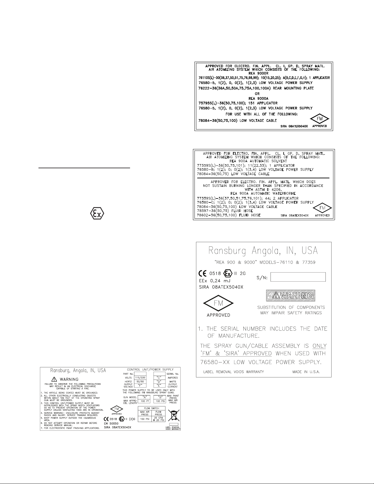
9. A recapitulation of the certication marking is
detailed in the "Atex" section, on the next page,
drawing numbers: 72562, 76858, 78974, and
79648.
10. The characteristics of the equipment shall
be detailed e.g. electrical, pressure, and voltage
parameters.
The manufacturer should note that, on being
put into service, the equipment must be accompanied by a translation of the instructions
in the language or languages of the country in
which the equipment is to be used and by the
instructions in the original language.
AA-99-02.5
6
REA Automatic Applicators - Atex
Ransburg
REA 900 and 9000 Automatic
Applicators 77539 and 76110 ATEX
Product Marking Denitions
Ex Certicate Number: Sira 08ATEX5040X
Sira = Notied Body performing EC-type exam-
ination
08 = Year of certication
ATEX = Reference to ATEX Directive
5 = Protection Concept Code (code 5 is titled
Encapsulation)
040 = Document serial number
X = Special conditions for safe use apply
Special conditions for safe use: The REA 77359
and 76110 Automatic Applicators shall only be
used with associated 76580-XX Control Unit.
Product Marking
II 2 G
Label 76858
Label 78974
Ex = Specic marking of explosive protection
II = Equipment Group hazardous area characteristics
2 = Equipment Category
G = Type of explosive atmosphere (gases, vapors,
or mists)
EEx 0.24mJ = The REA Automatic Applicators
77359 and 76110 are suitable for use in automatic
spraying installations complying with EN 50 050 as
they are a Type A class with a discharge energy
limit of 0.24mJ.
Label 72562
Label 79648
7
AA-99-02.5

Ransburg
INTRODUCTION
REA Automatic Applicators - Introduction
DESCRIPTIONS
The REA Automatic processes are an air atomized
method for electrostatically applying coatings to
objects. The REA Automatics apply a high voltage
DC charge to the applicator electrode, creating an
electrostatic eld between the atomizer and the
target object. The target is electrically grounded
through its support which may be either stationary
or moving.
A regulated pressure uid system delivers material
to the atomizer. At the time of triggering the applicator’s fan and atomization air is applied which
atomizes the material forming a spray mist. The
mist under the inuence of the electrostatic eld,
becomes electrically charged. The charged particles of material are attracted to, and deposited
on, the target. The forces between the charged
particles and the grounded target are sufcient to
turn most normal overspray around and deposit
it on the back surface of the target. Therefore,
a high percentage of the spray is deposited on
the target.
One of the many features of the REA Applicator
Automatic System is the electrical discharge which
is available from the resistive charging electrode is
limited to the optimum level of safety and efciency.
As the applicator electrode approaches ground,
the control unit and applicator circuitry shut down
the high voltage and current to the applicator. The
control unit must then be reset to continue to spray
electrostatically.
The REA Automatic Electrostatic Spray Applicators
are transformable between air spray and HVLP
spray technology. By changing a select few parts,
the applicator may be transformed to be operated
in either spray mode. (See “Spray Technology
Conversion Procedure” in the “Installation” section
for details.)
The REA 900A Applicator is designed with a mov-
ing trigger (shaft), so no forward mounted trigger
valve is required. The dump valve is mounted on
the rear bulkhead plate for ease of maintenance.
All uid connections in this applicator use “AN”
style ttings to eliminate “dead spots” in the uid
path for superior ushing.
The REA 9000R is a robot-mounted applicator for
hollow wrist robots produced by either FANUC or
ABB. The advantage of the REA 9000R applicator
is that it can be removed quickly and easily from
the robot mounting plate with the use of a threaded
retaining ring.
The REA 9000R incorporates two important safety
features. The rst being a break-away design
that will shear two (2) nylon mounting bolts if the
applicator comes in contact with the object being
sprayed. The second is the discharge which is
available from the resistive charging electrode is
limited to the optimum level of safety and efciency.
The REA 9000W (Not FM Approved) is an external
charge probe applicator designed to spray water-
borne coatings in systems utilizing a grounded uid
supply. Applicator features include: Probe Shroud
Air and Electrode Shroud Air. Low pressure air
exiting around the probe body and electrode wire
aid in keeping these components clean during op-
eration. These features help to maintain maximum
efciency of the applicators over a longer period
of time. The REA 9000W applicator also offers
conventional “classiC” high voltage technology.
The REA 9000R and 900A Series of applicators
apply -85kV DC charge to the coating materials at
the point of atomization. This series of applicators
is intended for use with grounded solventborne
coating systems. The REA 9000W Series of
applicators applies -70kV DC Charge. This elec-
trostatic charge allows a more efcient, uniform
application of coating material to the front, edges,
sides, and back of products. It is highly suitable
AA-99-02.5
8

REA Automatic Applicators - Introduction
Ransburg
for applying coatings to a variety of surface con-
gurations: large targets, small parts, tubular
wares, concave and recessed parts, etc. keeping
these components clean during operation. These
features help to maintain maximum efciency of
the applicators over a longer period of time.
These series of applicators include the automatic
applicator, low or high voltage cable, control unit,
uid hose, and air tubing.
The control unit provides voltage output to the
applicator and contains controls for AC on/off,
high voltage adjust, kV/microamp meter and triple
setpooint or analog input control.
NOTES
9
AA-99-02.5
Ransburg
REA Automatic Applicators - Introduction
Figure 1a: REA 9000R Solventborne Electrostatic Spray Applicator
AA-99-02.5
Figure 1b: View of Mounting Plate Assembly
10
REA Automatic Applicators - Introduction
NOTE
> To allow for ease of conguration,
operation, and modication of robot
teach patterns, the following X/Y verticles are provided (refer to Figure 2 for
explanation of coordinates). Optimum
spray pattern is achieved at a distance
of 10 - 14 inches from tip.
76110 REA 9000R 60
76110 REA 9000R 90
X Y
o
12.25 6.50
o
10.00 7.50
Ransburg
11
Figure 2: Applicator Tool-Point Representation REA 9000R Automatic
For use with Fanuc P-200 Robots, the following adapter plates must be used:
EO-3150-121-014 is for 100o wrist.
EO-3461-127-001 is for 140o wrist.
AA-99-02.5
Ransburg
REA Automatic Applicators - Introduction
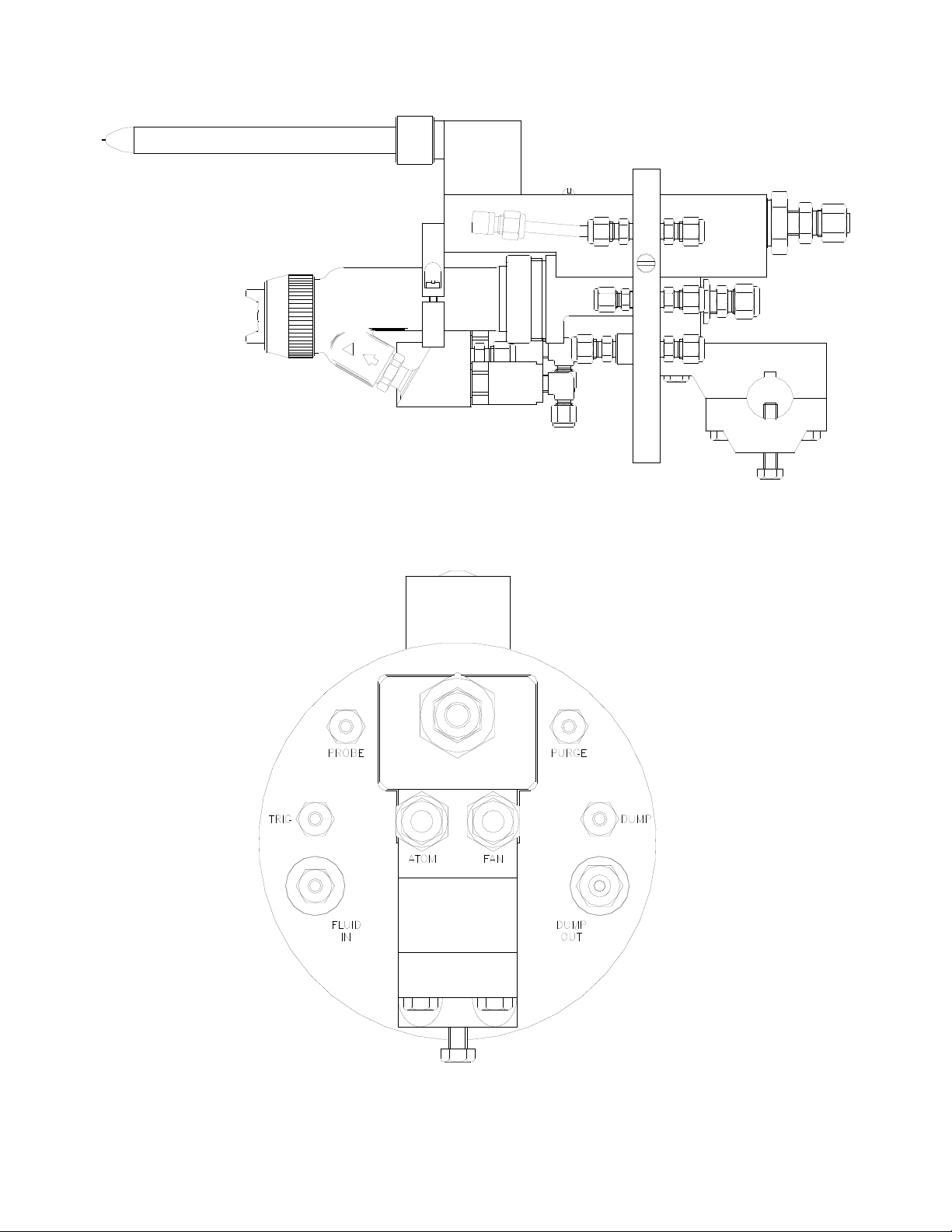
Figure 3a: REA 9000W Waterborne Electrostatic Spray Applicator
AA-99-02.5
Figure 3b: View of Back Plate
12
REA Automatic Applicators - Introduction
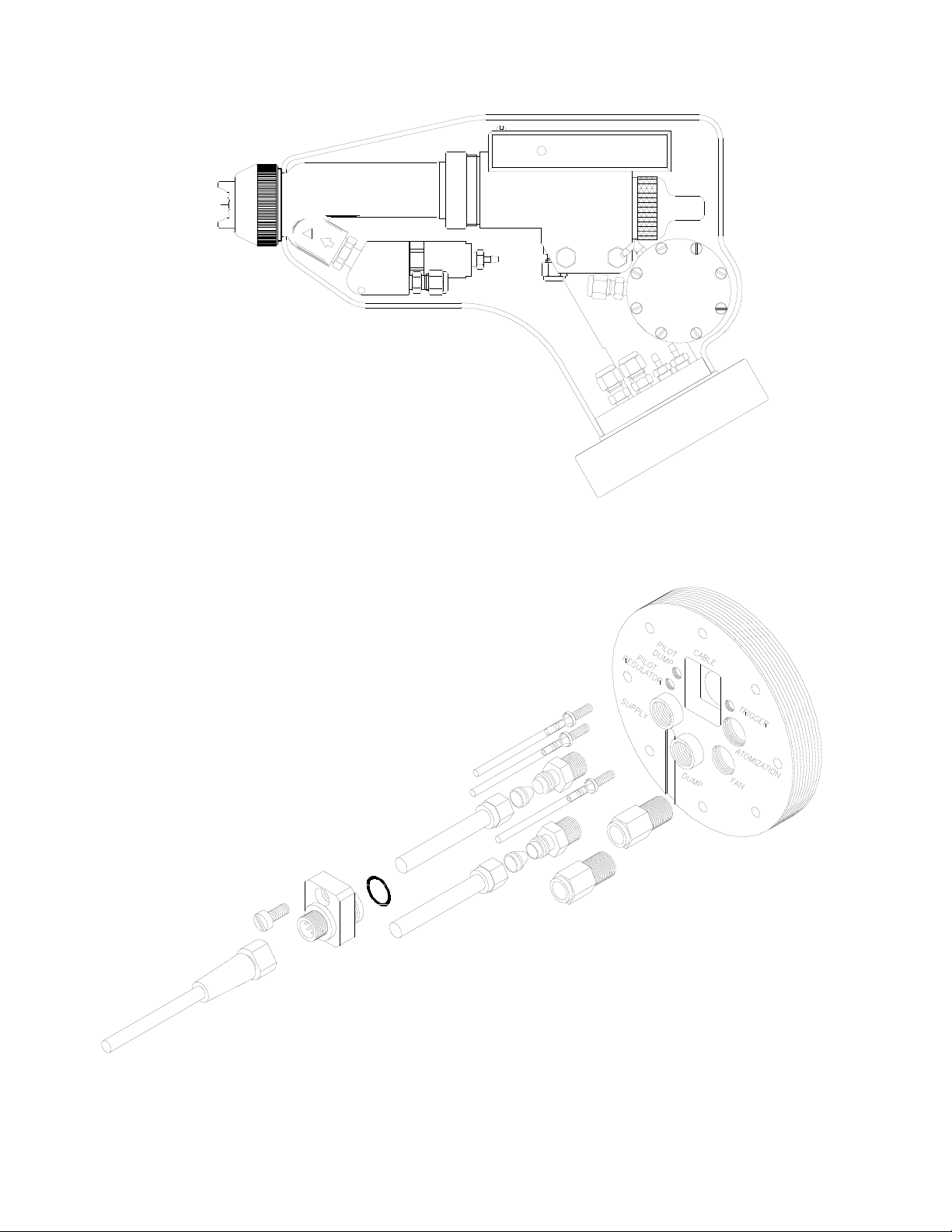
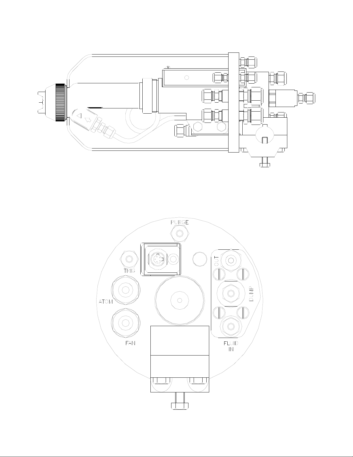
Figure 4a: REA 900A Solventborne Electrostatic Spray Applicator
Ransburg
13
Figure 4b: View of Back Plate
AA-99-02.5

Ransburg
REA Automatic Applicators - Introduction
SPECIFICATIONS SOLVENTBORNE REA 9000R
Electrical / Physical
Operating Voltage: 85kV DC [-] max.
Current Output: 120 microamperes max.
Weight: 41 oz. (1,162g)
Applicator Height: 6.5-inch (33.66cm)
Applicator Length: 13.25-inch (33.66cm)
Applicator Width: 2-inch (5.08cm)
Cable Lengths: 36-ft.
Atomizer Assembly: 4904-65R
4907-45
HVLP 75600-01
HVLP 75601-00
Fluid Flow Rate: Variable to 1,000 cc/min.
Operating Pressure (Air Spray):
Atomizing Air 0-100 psig (6.8 bar)
Fan Air 0-100 psig (6.8 bar)
Trigger Air 40 psig min. (2.7 bar)
100 psig max. (6.8 bar)
Fluid 0-100 psig (6.8 bar)
Operating Pressure (HVLP Spray):
Atomizing Air 0-100 psig (6.8 bar)
Fan Air 0-100 psig (6.8 bar)
Trigger Air 40 psig min. (2.7 bar)
100 psig max. (6.8 bar)
Fluid 0-100 psig (6.8 bar)
Piston Air Inlet
Size: 3/16” ODT
Atomization Air Inlet
Size: 3/8” ODT
Fan Air Inlet Size: 3/8” ODT
Fluid Inlet Size: 1/4” ODT
Paint Resistance*:
*(Ransburg Meter)
*( Ransburg Meter)
(Optional: 50, 75, and 100 ft.)
.1 MΩ to ∞
SPECIFICATIONS WATERBORNE REA 9000W
Electrical / Physical
Operating Voltage: 70kV DC [-] max.
Current Output: 120 microamperes
max. (Classic)
Weight: 82 oz. (2,325g)
Bulkhead Diameter: 6.69-inch (16.9cm)
Max Applicator Height: 7.90-inch (20.0cm)
Applicator Length: 16.51-inch (33.0cm)
Center Distance from Mount to:
Probe End 15.23-inch (38.6cm)
Nozzle End 11.80-inch (29.9cm)
Center Line of Nozzle 1.90-inch (4.8cm)
Center Line of Probe 5.92-inch (15.0cm)
Cable Lengths:
Classic Version 100 ft. max.
(SSW-1064 HVCable)
Atomizer Assembly: 4904-65R
4907-45
HVLP 75600-01
HVLP 75601-00
Fluid Flow Rate: Variable to 1,000 cc/min.
Operating Pressure (Air Spray):
Fluid 0-100 psi (6.8 bar)
Air 0-100 psi (6.8 bar)
Consumption 16 SCFM @ 50 psig
Operating Pressure (HVLP Spray):
Fluid 0-100 psig (6.8 bar)
Air 0-100 psig (6.8 bar)
Consumption 22 SCFM @ 50 psig
(input) for 10 psig
nozzle output
Atomization Air Inlet
Size: 3/8” NPT (F) 1/4” NPT
(F) 3/8” ODT
Fan Air InletSize: 3/8” NPT (F) 1/4” NPT
(F) 3/8” ODT
Fluid Inlet Size: 1/4” AN (F) 1/4” ODT
Dump Outlet Size: 1/4” AN(F) 3/8” ODT
Trigger Actuation: 1/4” ODT - 1/8” NPT (F)
Dump Actuation: 1/4” ODT - 1/8” NPT (F)
Probe Shroud/Knife
Air: 1/4” ODT - 1/8” NPT (F)
Shroud/Applicator
Cover Purge Air: 1/4” ODT - 1/8” NPT (F)
Applicator Mounting
Stud Diameter: .98” - 1.00”
Mount Woodruf Key Size: 1/4” Nominal
AA-99-02.5
14

REA Automatic Applicators - Introduction
Ransburg
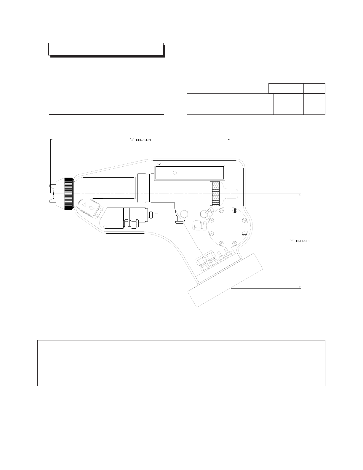
SPECIFICATIONS SOLVENTBORNE REA 900A
Electrical / Physical
Operating Voltage: 85kV DC [-] max.
Current Output: 120 microamperes max.
Weight: 84 oz. (2,100g)
Applicator Diameter: 5.50-inch (13.9cm)
Applicator Length: 14.85-inch (37.6cm)
Center Distance from Mount to:
Nozzle End 13.00-inch (32.9cm)
Center Line of
Nozzle 1.90-inch (4.8cm)
Cable Lengths: 36 ft.(std)
(Optional: 50, 75, and
100ft.)
Atomizer Assembly: 4904-65R
4907-45
HVLP 75600-01
HVLP 75601-00
Fluid Flow Rate:
Operating Pressure (Air Spray):
Fluid 0-100 psig (6.8 bar)
Air 0-100 psig (6.8 bar)
Consumption 16 SCFM @ 50 psig
Operating Pressure (HVLP Spray):
Fluid 0-100 psi (6.8 bar)
Air 0-100 psi (6.8 bar)
Consumption 22 SCFM @ 50 psig
(input) for 10 psig
nozzle output
Atomization Air Inlet
Size: 1/4” NPT (F) 1/2” ODT
Fan Air Inlet
Size: 1/4” NPT (F) 1/2” ODT
Fluid Inlet Size: 1/4” AN (F) 1/4” ODT
Dump Outlet Size: 1/4” AN (F) 3/8” ODT
Trigger Actuation: 1/8” NPT (F) 1/4” ODT
Dump Actuation: 1/8” NPT (F) 1/4” ODT
Shroud Purge Air: 1/8” NPT (F) 1/4” ODT
Gun Mounting Stud
Diameter: .98” - 1.00”
Mount Woodruf Key
Size: 1/4” Nominal
Paint Resistance*:
Variable to 1,000 cc/min
.1 MΩ to ∞
NOTES
.
15
AA-99-02.5
Ransburg
INSTALLATION
REA Automatic Applicators - Installation
W A R N I N G
!
> Install and route the hoses and cables so
they are NOT exposed to temperatures in ex-
cess of 120
bends are NOT less than a 6-inch (15 cm)
radius. Failure to comply with these parameters could cause equipment malfunctions that
might create HAZARDOUS CONDITIONS!
°F and so that all hose and cable
TYPICAL REA
AUTOMATIC
APPLICATOR
INSTALLATION
Connect the voltage cable to the control unit voltage
socket. Gently hand tighten the cable retaining
nut. Connect the other end of the voltage cable
to the receptacle at the rear mounting plate of the
applicator, using a wrench to tighten.
W A R N I N G
!
> The 9000W is is intended for use with
waterborne coating formulations only!
W A R N I N G
!
> The control unit MUST be located at least
three feet outside of the spray area. Install
units in accordance with the code requirements (see NFPA-33, OSHA, and local codes).
W A R N I N G
!
> The electrical discharge which is available
from the charging electrode must not exceed
0.25 mJ of energy. To achieve this limit, any
ow of energy from the paint supply through
the paint line to the applicator electrode
MUST BE prevented by grounding the paint
line at the inlet.
!
> DO NOT overtighten voltage cable con-
nection to applicator, as damage to plastic
parts may occur.
The control unit of cascade style applicators
MAY be connected through conduit with an ex-
plosion-proof terminal on or near the spray booth
where it will be convenient, or may be connected
with a line cord depending upon application requirement.
C A U T I O N
NOTE
> Refer to the Control Unit Service
manual for the “Circuit Diagram and
Instructions to Connect the Control Unit”.
> Verify that the paint inlet is actually ground-
ed BEFORE operating it! This is done with a
fully connected and operational system by
placing one lead of an ohmmeter to the inlet
tting and the other to the building electrical
ground (cold water pipe, building structure,
etc.). The reading should be essentially zero.
> If a greater reading is obtained, check that
the control unit is grounded. (See the Control
Unit manual for “Grounding Procedure”).
AA-99-02.5
16

REA Automatic Applicators - Installation
Ransburg
To Install the REA 9000W or
REA 900A
1. Mount the applicator to the reciprocator bar.
It is recommended to use a keyed bar with 1/4”
Woodruff key. The applicator may be mounted
on bars from the size .98-inch diam. (25 mm) to
1.00-inch diam. (27 mm). Tighten the ve (5)
mounting screws securely.
2. Run 1/4-inch ODT air line to the trigger line
tting.
NOTE
> All ttings may be replaced with
alternate ttings, depending on your
installation. (See “Specifications”
previously discussed in the “Introduction” section, for female thread size.
C A U T I O N
!
> Failure to connect the shroud purge air line
on the REA 900A Gun can allow excessive
corona to build up within the shroud and cause
premature failure of the barrel and transformer
assemblies.
6. Install 1/4-inch ODT air line for dump actuation.
7. Install 3/8-inch ODT uid line to dump out.
C A U T I O N
!
> Failure to use dump line will degrade color change time and applicator performance.
W A R N I N G
!
> Whenever the applicator is in the dump
or ush mode, the electrostatics must be off.
W A R N I N G
!
> ALL ttings used must be noncon-
ductive. The use of electrical conductive
tting may cause injury or re.
3. Run 3/8-inch ODT or 1/2-inch ODT uid line to
the applicator.
4. Connect atomization air and fan air lines. Depending upon atomization technology used, size
the line accordingly.
NOTE
> The atomization and fan air line should
always lead the trigger signal when the
applicator is on, and lag the trigger signal
when the applicator is off. Failure to follow
this procedure will cause applicator spits.
Filters
NOTE
> For optimum nish quality use clean,
dry ltered air.
1. Install a uid lter on the output of uid supply,
as shown in Figure 5.
2. Detail depends on whether pressure tank,
pump unit, recirculating system, etc., is used. The
lter must be installed vertically with drain valve
down and arrow pointing in direction of ow.
17
5. Install 1/4” ODT air line to shroud or probe
purge air. Set pressure between 5-10 psig.
Figure 5: Typical Fluid Filter Installation
AA-99-02.5

Ransburg
REA Automatic Applicators - Installation
Paint Preparation
A proper paint mixture is essential to electrostatic
operation. Paint test equipment may be obtained
through your Ransburg representative. Consult
Ransburg “Paint Related Information for REA and
REM Applicators” manual, for paint formulation
information. For further paint formu-lation and
testing procedures, consult your Ransburg representative and/or your paint supplier.
Spray Technology Conversion
Procedure
Remove existing retaining ring and air cap from
end of applicator. Remove uid nozzle using
applicator wrench 19749-00.
C A U T I O N
!
> To avoid damage to the uid nozzle and
electrode, the paint pressure and trigger return
spring tension MUST be released by triggering
the applicator prior to removing the uid nozzle.
Atomizer Assembly Selection
The “Atomizer Assembly Selection Chart” is provided to give you a comparison of the air caps
and uid nozzles. THE CHOICE OF ATOMIZER
ASSEMBLY SHOULD DEPEND ON QUALITIES
DESIRED AND MUST BE VERIFIED BY ACTUAL
TRIAL. See your authorized Ransburg electro-
static distributor for atomizer demonstration.
Spray Pattern Adjustment
The spray pattern of fan atomizers is adjustable
from a small circle to an elongated oval, approximately 10 to 18-inches across the usable long
axis at 8 to 12-inches from the target. The swirl
atomizer assemblies produce a round pattern
from 5 to 9-inches in diameter. To adjust pattern
size, increasing fan air pressure will expand the
pattern, a reduction will decrease it. To change
the spray pattern axis of fan atomizers from
horizontal to vertical, loosen retainer ring, rotate
the air cap clockwise to the desired position and
gently tighten the ring.
> The applicator MUST be tilted front down to
remove the uid nozzle. Failure to do so may
allow paint to enter the air passages, thereby
reducing air ow and damaging the applicator
barrel or cause electrical shorting. Applicators
may be ushed in lieu of tilting, but they MUST
be either ushed or tilted BEFORE removing
the uid nozzle!
With a bladed screwdriver, remove pressure
reducers by turning counter-clockwise from barrel. Install the desired pressure reducer. Apply
suitable liquid pipe thread sealant to threads.
Install appropriate uid nozzle, gently tightening
into place using the applicator wrench 19749-00.
Reinstall appropriate air cap and retaining ring.
(See “Nozzle Selection Chart” later in this section,
for proper combination of air caps, uid nozzles
and pressure reducers).
For remote HVLP fan air applications fan control,
air pressure should not exceed 10 psi. Fan control pressure should be adjusted depending upon
pattern size desired.
C A U T I O N
!
> A counter-clockwise turn of the air cap may
loosen the uid nozzle and cause air to get
into the paint or paint to cross over into the air
passages.
Applicator To Target Distance
Mount the applicator 6 to 12-inches maximum
from the target for best operation. (A higher
transfer efciency will be achieved at the closer
target distance).
AA-99-02.5
18

REA Automatic Applicators - Installation
Ransburg
Wiring The Unit
The REA 9000R comes with a complete cable
from the mounting plate.
W A R N I N G
!
> If the REA 9000R cable must be terminated
at the robot, it must be done within a suitable
explosion proof enclosure.
ATOMIZER ASSEMBLY SELECTION
REA NOZZLES (Conventional Spray)
Air Cap Part
Number
Fluid Nozzle Part
Number
Oriface
The cable from the control unit of the REA 9000R
should be run through suitable conduit and con-
nected at the robot explosion proof enclosure, if
necessary.
Pressure
Reducer
(Black)
ID
Separate
Retaining Ring
70899-00 70898-00 Swirl 4903-00 74963-02
LREA0002 LREA0003 Round 73569-00 74963-02
4904-65R 4907-44 .055 73569-00 74963-02
4904-65R 4907-45 .070 73569-00 74963-02
4904-65R 4907-46 .042 73569-00 74963-02
4904-65R 4907-47 .028 73569-00 74963-02
4904-65R 4907-48 .047 73569-00 74963-02
4904-63 4907-44 .055 73569-00 74963-02
4904-63 4907-45 .070 73569-00 74963-02
4904-63 4907-46 .042 73569-00 74963-02
4904-63 4907-47 .028 73569-00 74963-02
4904-63 4907-48 .047 73569-00 74963-02
4904-98 4907-44 .055 73569-00 74963-02
4904-98 4907-45 .070 73569-00 74963-02
4904-98 4907-46 .042 73569-00 74963-02
4904-98 4907-47 .028 73569-00 74963-02
4904-98 4907-48 .047 73569-00 74963-02
REA NOZZLES (HVLP)
Air Cap
Part Number
Fluid Nozzle
Part Number
Oriface
ID
Separate
Retaining
Ring
Pressure
Reducer
(White)
19
75601-00 75600-01 .055 73569-00 74963-03
75601-00 75600-02 .070 73569-00 74963-03
75601-00 75600-03 .086 73569-00 74963-03
AA-99-02.5

Ransburg
MAINTENANCE
REA Automatic Applicators - Maintenance
W A R N I N G
!
> The user MUST read and be familiar with
the SAFETY INSTRUCTIONS in this manual.
> If compressed air is used in cleaning, REMEMBER THAT HIGH PRESSURE AIR CAN
BE DANGEROUS AND SHOULD NEVER BE
USED AGAINST THE BODY. It can blind,
deafen and may even penetrate the skin. If
used for cleaning equipment, the users should
wear safety glasses.
> ALWAYS turn the control unit power off prior
to cleaning or servicing equipment.
> Be SURE the power is OFF and the system
is grounded BEFORE using solvent to clean
ANY of the equipment.
> DO NOT OPERATE A FAULTY APPLICATOR!
C A U T I O N
!
> NEVER remove the uid nozzle assembly
while paint is in the gun or paint may clog the
air passages. Clogged air passages will cause
poor atomization and electrical shorting. Air
passages which are clogged with conductive
material may lead to excessive current output
levels and consequent low operating voltage
and long range electrical damage. Before undertaking any atomizer assembly procedure,
see “Atomizer Assembly Cleaning Procedure”.
> The applicator MUST be tilted front down
to remove the air cap and/or uid nozzle.
Failure to do so may allow paint to enter the
air passages, thereby reducing air ow and
damaging the applicator barrel/cascade.
Applicators may be ushed in lieu of tilting.
However, they must be either ushed or tilted
down!
> When using cleaning solvent, standard
health and safety precautions should apply.
ROUTINE SCHEDULE
Follow these maintenance steps to extend the life
of the applicator and ensure efcient operation.
Several Times Daily
• Turn the control unit power to OFF!
• Inspect the air cap for paint accumulation.
Clean as frequently as necessary with a soft
bristled brush and a suitable solvent, and
blow clean.
• Clean all insulating surfaces in the system.
Remove paint accumulation from the exteriorof
the applicator, low voltage cable and air
lines with a solvent dampened cloth. Use only
non-polar (non-conductive) solvent.
W A R N I N G
!
> NEVER soak or submerge the electrical
components of the applicator (i.e. barrel, transformer, cable). Damage and failure may occur.
Daily (at the start of each shift)
• Verify that ALL solvent safety containers are
grounded!
• Check within 20 feet of the point of operation
(of the applicator) and remove or ground ALL
loose or ungrounded objects.
AA-99-02.5
20

REA Automatic Applicators - Maintenance
Ransburg
• Inspect workholders for accumulated coating
materials, removing such accumulations.
• Check that atomizer assembly is clean and
undamaged.
• Straighten the applicator electrode if
necessary.
C A U T I O N
!
> When straightening the electrode, be
careful not to distort the uid nozzle orice.
• Clean the uid lter, if used.
• Turn the control unit power ON. The
applicatorred transformer light should light
when triggered.
• Run a current/voltage output test.
Electrical Current Output Test
1. Turn the paint supply OFF.
2. Turn high voltage on at applicator.
3. Slowly approach the applicator electrode to any
grounded object and make contact.
4. Monitor the current output reading on the
voltage supply meter. As applicator approaches,
ground current should increase near 100 mA
overload current should “trip,” shutting “off” high
voltage. Overload indication should come on.
5. Release the trigger and turn the control unit
power OFF.
If the control unit does not trip, DO NOT use the
applicator until the problem has been corrected.
(See the “Troubleshooting Guide” in the “Maintenance” section of this manual).
Shut-Down
(and at the end of each shift)
1. Turn the control unit power OFF.
2. Turn the paint supply OFF.
3. Turn the atomizing air and fan air OFF.
4. Wipe the applicator, cable and hoses with a rag
and a suitable non-polar (non-conductive) solvent.
5. Flush the lines and allow the solvent to remain
in the lines unpressured. (See “Flushing Procedures” in the “Maintenance” section of this manual).
NOTE
> If the shutdown is to be short, the lines
may not require ushing, depending on
the coating material being used. If the
solids in the material settle slowly, the
lines will not need to be ushed as soon
after shut-down as with fast settling
solids. The paint being used and the
length of time that the lines will be shutdown will determine the need for ushing. Metallic paint and primer will require
ushing sooner than some other kinds
of coating materials.
C A U T I O N
!
> If the coating material is fast settling and
if the lines are not ushed soon enough, the
applicator’s uid passages as well as the lines
may become clogged and cause excessive
down time and/or service and repair.
Weekly
• Check the entire system for damage, leaks
and paint accumulation.
21
• Clean the atomizer assembly.
AA-99-02.5

Ransburg
REA Automatic Applicators - Maintenance
ATOMIZER ASSEMBLY
CLEANING PROCEDURE
Routine Cleaning Equipment
Needed
• An appropriate non-polar (non-conductive)
solvent.
• A solvent safety container (grounded).
• A small soft-bristled brush.
• The Ransburg 19749-00 special Multi-
Purpose Wrench from the Installation Kit.
C A U T I O N
!
> To avoid damage to the uid nozzle, nee-
dle/electrode, the paint pressure MUST be
released by triggering the applicator prior to
removing the tip.
W A R N I N G
!
> NEVER wrap the applicator in plastic to keep
it clean. A surface charge may build-up on the
plastic surface and discharge to the nearest
grounded object. Efciency of the applicator
will also be reduced and damage or failure of
the applicator components may occur. WRAP-
PING THE APPLICATOR IN PLASTIC WILL
VOID WARRANTY.
Proceed as follows:
1. Turn the control unit power OFF.
2. Release the trigger.
3. Turn the paint ow OFF.
4. See “Disassmbly Procedure” in the ”Maintenance” section.
> The applicator MUST be tilted front down
to remove the air cap and/or uid nozzle.
Failure to do so may allow paint to enter the
air passages, thereby reducing air ow and
damaging the applicator barrel/cascade. Ap-
plicators may be ushed in lieu of removing
nozzles. However, they must be either ushed
prior to, or tilted down during nozzle removal!
> The control unit power MUST always be
off when removing the nozzles or any other
service to the applicator.
> Using any tool other than the Ransburg
19749-00 wrench to remove or reinstall
the uid nozzle may distort or damage it.
For efcient operation, keep the applicator’s exte-
rior and the voltage cable clean and free of paint
accumulation and dirt. This prevents the loss of
voltage to ground with a resulting reduction in
electrostatic effect. Paint accumulation at the air
cap orices reduces atomization quality and increases the potential for paint spits. Clean the air
cap with a brush and solvent as often as needed
to ensure good atomization.
W A R N I N G
!
> Any damage to the gun may result in UNSAFE operating.
5. Clean the removed parts with a soft brush
and suitable solvent.
C A U T I O N
!
> Metal tools and wire brushes must NEVER
be used. NEVER use a cleaning tool that
is harder than the plastic parts. If a deposit
cannot be removed with solvent and a rag or
soft brush, soak the part in the solvent ONLY
until the deposit can be removed! NEVER
SOAK THE APPLICATOR BODY, BARREL,
OR TRANSFORMER!
AA-99-02.5
22

REA Automatic Applicators - Maintenance
Ransburg
FLUSHING PROCEDURES
1. Turn the control unit power OFF.
2. Turn the paint supply OFF.
3. Turn the atomizing air supply OFF.
4. Activate dump air and ush with solvent until
it is clear of paint. Air purge the dump line.
5. De-activate dump air and activate trigger air
until the applicator uid passage is clear.
6. Disconnect the solvent supply.
7. Activate the trigger valve until it is clear of
solvent. After the preceding steps are complete,
the applicator is ready for color change, storage
or service.
NOTES
23
AA-99-02.5

Ransburg
REA Automatic Applicators - Maintenance
TROUBLESHOOTING GUIDE
General Problem Possible Cause Solution
DEFECTIVE SPRAY PATTERN
Pattern will not
shape
Pattern heavy at
one end
Extremely heavy
spitting or severely
deformed pattern.
DEFECTIVE DELIVERY
Air
Fluid
1. Clogged or faulty fan valve remote
fan air line
2. Air passages in applicator or air
feed lines clogged
3. Worn, faulty or clogged air cap
1. Clogged or faulty air cap
2. Clogged or faulty uid nozzle
1. Wrong air cap/uid nozzle
combination
2. Timing of uid on and air on is not
adjusted
1. Air passages in applicator or air feed
lines clogged
2. Decient source air
3. Paint in air passage
1. Clogged or faulty uid nozzle
2. Clogged passages in applicator uid
tube or uid feed lines
3. Insufcient needle/electrode travel
4. Low source pressure
5. Clogged uid lter
6. Clogged or obstructed ball valve or
uid regulator
1. Clean, replace or repair.
2. Blow out.
3. Clean or replace.
1. Clean or replace.
2. Clean or replace.
1. Ensure proper uid nozzle/air
nozzle pressure reducer
combinations (see chart).
2. Check programming se quence.
1. Blow out.
2. Increase.
3. Clean and blow out.
1. Flush or replace.
2. Flush.
3. Adjust (see “Trigger Nut
Adjustment”).
4. Increase.
5. Clean or replace.
6. Clean as required.
AA-99-02.5
LEAKAGE
Air
Fluid (at rear of
barrel)
Fluid (sight at nozzle
when trigger is
released)
1. Loose or defective ttings
1. Packing, chevron seals and/or
needle /electrode shaft defective
1. Nozzle not secure
2. Trigger valve closing before uid
nozzle valve
1. Tighten or replace.
1. Tighten needle or replace.
1. Tighten.
2. Check programming
sequence.
24

REA Automatic Applicators - Maintenance
TROUBLESHOOTING GUIDE (Cont.)
General Problem Possible Cause Solution
LEAKAGE (Cont.)
Ransburg
Fluid (constant at
nozzle)
ELECTRICAL
Wrap Back
Improper or No HV
1. Worn or damaged uid nozzle seat
2. Worn or damaged needle/electrode
3. Nozzle not secure
4. Trigger valve needle seat
1. Improper target ground
2. Improper booth exhaust
3. Excessive atomizing air
1. Faulty cable connections
2. Faulty transformer assembly
3. Improper or no ground
4. Faulty barrel/cascade assembly
5. Faulty low voltage cable
6. Faulty high voltage cable
7. Faulty control unit
8. Check fuses
9. > IS THE POWER TURNED ON?
> IS THE ATOMIZING AIR
TURNED ON?
> IS THE (RED LIGHT) TRANS FORMER ON?
>
IS THE PAINT TOO CONDUCTIVE?
10. Paint in air passages
1. Replace uid nozzle.
2. Replace.
3. Tighten.
4. Rebuild valve.
1. Trace and correct.
2. Trace and correct.
3. Reduce fan and atomization
pressure.
1. Check and secure at the
applicator and at the control
unit.
2. Replace.
3. Trace and correct.
4. Replace.
5. Replace.
6. Replace.
7. See the Control Unit manual.
8. Replace.
9.
10.Clean passages with soft
bristled brush
25
High Current Draw 1. Paint in air passages
2. Dirty dump line
3. Paint in dump line
4. Dirty applicator exterior
1. Clean passages with soft
bristled brush
2. Clean or replace dump line;
always use lines.
3. Review air push cycle
4. Clean with appropriate sol vent and install new applicator
cover.
AA-99-02.5

Ransburg
SERVICE - REA 9000W SERIES
REA Automatic Applicators - Maintenance
All repairs should be made on a clean, at surface. If a vise is used to hold parts during service
or repair, DO NOT clamp onto plastic parts and
always pad the vise jaws!
The following parts should be thoroughly packed
with LSCH0009-00 dielectric grease leaving NO
air space or voids when assembling.
• All o-rings (o-rings do not need lubrication),
chevron seals and all internal and external
threads.
C A U T I O N
!
> Failure to pack the needle electrode/electrode
shaft assembly and packing tube MAY CAUSE
lower electrical output of the applicator.
• Needle shaft LREA4005-00
• Transformer assembly LREA4004-00
REPLACEMENT
PROCEDURE
(REA 9000R, 9000W and 900A)
C A U T I O N
!
> ALWAYS remove the applicator from the
work site for service or repair! DO NOT USE
any silicone lubricants in order to avoid paint
defects.
W A R N I N G
!
> PRIOR to performing a applicator removal, be
sure ALL power to the control unit is turned off.
TO REMOVE THE
APPLICATOR FROM THE
EQUIPMENT REQUIRED
(REA 9000R, 9000W and 900A)
• 19749-00 spanner (nozzle) wrench (3 in 1)
for barrel nut, uid nozzle, and
needle shaft assembly
• Screwdriver (broad)
• Dielectric grease (59972-00) or
LSCH0009-00
• 1/2-inch (13mm) nut driver
• 9/16-inch socket and handle
• Adjustable wrenches
WORK SITE
1. Turn the control unit power OFF.
2. Detach voltage cable from applicator.
3. Turn the paint supply OFF.
4. Turn the atomizing air supply OFF.
5. Properly ush the applicator.
6. Remove air actuation ttings.
7. Remove uid in and out lines.
8. Remove the applicator from the work site
(and voltage cable, if necessary).
AA-99-02.5
26

REA Automatic Applicators - Maintenance
Ransburg
NOZZLE AND
ELECTRODE CLEANING
OR REPLACEMENT
(REA 9000W)
C A U T I O N
!
> NEVER bend the electrode!
NOTE
> See “Atomizer Assembly Cleaning
Procedure” previously discussed in this
section.
W A R N I N G
!
> NEVER shorten the electrode wire.
Air Cap
1. Unscrew retaining ring, remove air cap from
barrel and clean using proper method or replace
it.
Fluid Nozzle
C A U T I O N
!
> To avoid damage to the uid nozzle, needle/
electrode, the paint pressure MUST be released
by triggering the applicator prior to removing
the tip.
> The applicator MUST be tilted front down to
remove the air cap and/or uid nozzle. Failure
to do so may allow paint to enter the air passag-
es, thereby reducing air ow and damaging the
applicator barrel/cascade. Applicators may be
ushed in lieu of removing nozzles. However,
they MUST be either ushed or tilted down
BEFORE removing the uid nozzle!
> The control unit power MUST always be off
when removing the nozzles.
C A U T I O N
!
> Using any tool other than the Ransburg
19749-00 wrench to remove or reinstall the
uid nozzle may distort or damage it.
> Over-tightening of plastic parts may cause
breakage.
2. Replace air cap and tighten retaining ring back
onto the barrel.
27
1. Remove air cap and retaining ring from barrel
and clean or replace it.
2. With the nozzle wrench on wrench ats,
remove uid nozzle from barrel.
3. Clean or replace uid nozzle using appropri-
ate cleaning method.
4. Screw the cleaned or new uid nozzle into
barrel and secure with the nozzle wrench.
5. Screw retaining ring over the air cap onto
barrel.
AA-99-02.5

Ransburg
REA Automatic Applicators - Maintenance
NOTE
> If the uid nozzle is replaced, there is
a good chance that the needle/electrode
assembly will need to be replaced, too.
Needle / Electrode - REA 9000W
Only
1. Unscrew probe retaining nut and pull probe
straight out of the probe holder body.
2. Unscrew the rear plastic plunger nut of the
probe assembly and remove.
3. Gently tap the probe body against your hand
until the needle assembly falls loose. Pull the
needle assembly out of the probe body.
4. By hand, unscrew (counter-clockwise) or
where necessary gently use needle nose pliers
on the needle/electrode ridges to remove it from
the needle shaft assembly. Clean as necessary
using appropriate cleaning procedure.
To Test - (REA 9000W)
1. Install electrode on front end of an available
18865-04 needle shaft. Be sure that electrode
is completely seated for proper contact between
metal shaft and conductive threaded insert in rear
of resistor.
2. Using a VOM meter that will read 15 megohms accurately, connect one meter lead to the
metal needle shaft and the other lead to the wire
at front of electrode. Electrode should be 14.5
to 19 megohms (nominal 15 megohms at 9 volts
or 11 to 17 megohms at 1000 volts). Electrodes
outside this range must be replaced (see Figure 6).
5. Inspect needle assembly components for signs
of high voltage arcing. Replace if necessary.
C A U T I O N
!
> DO NOT use dielectric grease inside the
probe assembly. Air must be able to ow freely
through this assembly.
6. If LREA4001 Resistive Electrode is being
replaced, it must be trimmed to the proper length.
Reassemble the probe with the new electrode.
Trim the electrode wire 1/16-inch from the end of
the probe body.
Figure 6: Testing Resistive Electrode
AA-99-02.5
28

REA Automatic Applicators - Maintenance
Ransburg
BARREL ASSEMBLY
REMOVAL
(REA 9000W)
1. Remove air cap retaining ring.
2. Pull shroud or applicator cover straight off the
applicator exposing the trigger/dump and barrel
assemblies.
3. REA 9000W ONLY- remove the high voltage
module to barrel mounting bracket.
4. Loosen barrel nut with spanner wrench.
5. Pull barrel and automatic body STRAIGHT
apart. Take extra care in handling barrel assembly
to prevent damage.
6. Remove the color valve manifold assembly by
turning the nut counter-clockwise until loose, then
pull the manifold straight out of the barrel.
7. Remove the trigger valve. Remove the ferruled
connector for the uid tube. Remove the coiled
uid tube by removing the ferruled connector at
the trigger valve manifold.
BARREL DISASSEMBLY
(REA 9000W)
1. Remove needle shaft assembly from rear of
the barrel with the 19749-00 spanner wrench.
2. Firmly pull the needle/electrode shaft assembly
out of the packing chamber.
C A U T I O N
!
> During this operation, be CAREFUL that
the interior surface of packing chamber is NOT
damaged (marred or scratched)! This chamber
is a seal area and the barrel assembly will have
to be replaced if it is damaged.
3. Unscrew needle/electrode from shaft and slide
parts off of the shaft (see Figure 7).
4. Inspect and replace parts as necessary. Since
the needle shaft in the REA 9000W does not
move, the packing wear should be minimal.
Rear
29
NOTE
> There is no need to remove retaining
ring or barrel nut from barrel unless they
are damaged. If they are to be removed,
lift one end of ring out of its groove and
spiral it off of the end of the barrel. The
nut can be removed. To replace them
on the barrel, slide nut onto the barrel,
place ring against the back of the barrel,
lift one end of it onto the barrel and spiral
it on and into its groove.
C A U T I O N
!
> Firmly spreading the retaining ring may
break it!
Front
Conductive
Retainer
Figure 7: Chevron Seal Assembly
AA-99-02.5

Ransburg
REA Automatic Applicators - Maintenance
BARREL REASSEMBLY
(REA 9000W)
• Clean all parts with a suitable non-polar
(non-conductive) solvent.
• If the electrode wire is bent, straighten it CARE-
FULLY by hand or use needle nose pliers.
• Check all parts for damage or wear. Replace
those that are damaged or worn with new
parts.
• Replace chevron seals with new parts.
• From time to time it is desirable to test the
electrical integrity of the LREA4001-00 resistive electrode (see “To Test“ in the “Service
for 9000W” in the “Maintenance” section).
3. Place male nonconductive chevron adaptor
onto shaft with the convex end rearward.
NOTE
> The chevron adaptors and chevron
seals should seat together to form an
unbroken seal.
4. Screw needle/electrode onto shaft and hand
tighten.
5. When replacing the needle/electrode on the
needle shaft of the REA 9000W applicator ONLY,
the electrode wire MUST be trimmed OFF ush
with the electrode body. Failure to do so may
allow the uid supplylLine to become charged,
thus reducing available voltage at the external
probe electrode.
C A U T I O N
!
> To avoid damage to the chevron seals, they
MUST be installed from the rear of the barrel.
1. Place conductive female chevron adaptor onto
the front of shaft with the concave side toward
the front.
2. Screw the four (4) new chevron seals onto
shaft, concave sides forward.
C A U T I O N
!
> DO NOT push the chevron seals straight
onto the shaft. The shaft threads may damage
the chevron bore and cause the applicator to
leak uid.
> Inspect needle/electrode shaft sealing surface for wear. If it is rough or uneven, replace it.
NOTE
> Apply a coating of dielectric grease
to the chevron seals and needle shaft.
C A U T I O N
!
> FAILURE to coat the needle shaft assem-
bly MAY CAUSE lower electrical output of the
applicator.
6. Insert the assembled items through the rear
barrel packing chamber of the barrel/cascade
assembly.
C A U T I O N
!
> DO NOT over-tighten. Over-tightening may
result in stripped threads or cracked barrel.
AA-99-02.5
30

REA Automatic Applicators - Maintenance
Ransburg
BARREL TO BODY
ASSEMBLY
(REA 9000W)
1. Slide gasket over the rear end of the barrel
assembly. Lightly coat cascade high voltage connections with LSCH0009-00 dielectric grease.
2. Tighten retaining ring with 19749-00 spanner
wrench.
C A U T I O N
!
> Nut should be secured hand tight only.
NEVER apply more than 10 lb•ft torque.
HIGH VOLTAGE MODULE
ASSEMBLY
4. Remove module retaining screw from the top
of the module.
5. Remove the two (2) 1/4-20 screws that attach
the rear bulkhead plate to the high voltage module.
These screws are accessed through holes in the
sides of the bulkhead plate.
6. Pull the high voltage module STRAIGHT out
through the bulkhead plate.
7. Install new high voltage module and assembly
in reverse order.
NOTE
> Generously lubricate probe body
metal plunger and high voltage module
contact bore with LSCH0009-00 dieletic
grease.
REPLACEMENT
(REA 9000W Only)
W A R N I N G
!
> Turn OFF all power, air and uid at the source.
C A U T I O N
!
> The voltage cable MUST be removed before
removing the high voltage module.
1. Remove the voltage cable from the rear of the
high voltage module assembly.
2. Remove the high voltage module to barrel
mounting bracket.
3. Remove the four (4) 1/4-20 at head screws
in the top of the probe holder body assembly.
Remove the probe AND body as ONE assembly.
LOW VOLTAGE CABLE
REPLACEMENT
(REA 900A Only)
W A R N I N G
!
> Ensure control unit power is OFF before dis-
connecting cable from applicator or control unit.
Disassembly:
1. Using wrench on connector ats, disconnect
low voltage cable from connector assembly.
2. Disconnect other end of low voltage cable from
control unit and remove cable from system.
31
AA-99-02.5

Ransburg
REA Automatic Applicators - Maintenance
Assembly:
1. Connect low voltage cable to control unit;
hand tighten.
2. Connect other end of low voltage cable to connector assembly using a wrench on the connector
ats to tighten.
C A U T I O N
!
> DO NOT overtighten low voltage cable con-
nection to spray applicator as damage to plastic
parts may occur.
VALVE BODY SERVICE
(REA 9000W)
When service is performed on any of the body
elements, it is best to remove the barrel and high
voltage module / transformer assembly to avoid
damage to the nozzle, electrode or any of the
plastic parts.
TO RETURN THE SPRAY
APPLICATOR TO THE
WORK SITE
1. Attach applicator to mounting bar and secure
screws.
2. Attach the air line to applicator air ttings.
3. Attach uid hose to uid hose tting.
4. Attach and secure the low/high voltage cable
to the spray applicator.
5. Turn the power, air and uid on at the source
and return the applicator to service.
After the disassembly of any body element:
• Clean all parts with a suitable clean solvent.
• Check all parts for damage or wear. Replace
those that are damaged or worn with new
parts.
AIR VALVE BODY
DISASSEMBLY
(REA 9000W)
1. Remove barrel assembly (see “Barrel Removal for the 9000W”, previously discussed in
this section).
2. Remove high voltage module/transformer
assembly (see “Transformer Assembly Replace-ment, for the 9000W”, previously discussed
in this section).
3. Remove two (2) back plate screws.
AA-99-02.5
32

REA Automatic Applicators - Maintenance
SERVICE - REA 9000R AND REA 900A SERIES
Ransburg
BARREL ASSEMBLY
REMOVAL
(REA 9000R & 900A)
C A U T I O N
!
> Firmly spreading the retaining ring may
break it!
1. REA 900A ONLY - Remove pneumatic and
uid lines from the front of the bulkhead plate.
Remove the bulkhead plate.
2. Remove rear housing and two (2) springs.
3. Using an adjustable wrench on the ats of the
valve rod extension, remove the air valve adjusting,
and air valve lock nut.
4. Disconnect coiled uid tube at the uid inlet
tting.
NOZZLE AND
ELECTRODE CLEANING
OR REPLACEMENT
(REA 9000R & 900A)
C A U T I O N
!
> NEVER bend the electrode!
NOTE
> See “Atomizer Assembly Cleaning
Procedure” previously discussed in this
section.
W A R N I N G
!
> NEVER shorten the electrode wire.
5. Loosen barrel nut with 19749-00 spanner
wrench.
6. Pull the barrel and automatic body STRAIGHT
apart. Take extra care in handling barrel assembly
to prevent bending of the extension valve rod.
NOTE
> There is no need to remove retaining
ring or barrel nut from barrel unless they
are damaged. If they are to be removed,
lift one end of ring out of its groove and
spiral it off of the end of the barrel, then
barrel nut can be removed. To replace
them on the barrel, slide nut onto the barrel, place ring against the back of the barrel, lift one end of it onto the barrel and
spiral it on and into its groove.
Air Cap
1. Unscrew retaining ring, remove air cap from
barrel, and clean using proper method or replace it.
2. Replace air cap and tighten retaining ring back
onto the barrel.
33
AA-99-02.5

Ransburg
REA Automatic Applicators - Maintenance
Fluid Nozzle
C A U T I O N
!
> To avoid damage to the uid nozzle, needle/
electrode, the paint pressure MUST be released
by triggering the applicator prior to removing
the tip.
> The applicator MUST be tilted front down to
remove the air cap and/or uid nozzle. Failure
to do so may allow paint to enter the air passag-
es, thereby reducing air ow and damaging the
applicator barrel/cascade. Applicators may be
ushed in lieu of removing nozzles. However,
they MUST be either ushed or tilted down
BEFORE removing the uid nozzle!
> The control unit power MUST always be off
when removing the nozzles.
5. Screw the cleaned or new uid nozzle into barrel
and secure with the nozzle wrench.
6. Screw retaining ring over the air cap onto
barrel.
NOTE
> If the uid nozzle is replaced, there is
a good chance that the needle/electrode
assembly will need to be replaced, too.
BARREL DISASSEMBLY
(REA 9000R and 900A)
1. Remove packing nut from rear of the barrel
with the 19749-00 spanner wrench.
C A U T I O N
!
> Using any tool other than the Ransburg
19749-00 wrench to remove or reinstall the
uid nozzle may distort or damage it.
> Over-tightening of plastic parts may cause
breakage.
1. Remove air cap and retaining ring from barrel
and clean or replace it.
2. Prior to removing the uid nozzle from the
applicator barrel, the trigger must be actuated
by applying air pressure to the trigger port or by
removing the rear piston housing and pulling back
on the needle shaft assembly. This will prevent
damage to the inside sealing surface of the uid
nozzle or the sealing taper of the electrode.
2. Firmly pull the needle/electrode shaft as-
sembly using the extension valve rod out of the
packing chamber:
• Resistive Electrode Accessory
• Male Chevron Adapter
• Chevron Seals (4 required)
• Female Chevron Adapter (conductive)
• Needle/Electrode Shaft
• Packing Tube
• O-Ring
• Rear Seal Retainer
• U-Cup (spring loaded)
• Spacer and (Belville) Spring Washers
(6 required)
3. Remove extension valve rod and adjustin nut
with two (2) 3/8” wrenches.
• Check all parts for damage or wear. Replace
those that are damaged or worn with new
parts.
3. With the nozzle wrench on wrench ats, remove
uid nozzle from barrel.
4. Clean or replace uid nozzle using appropri-
ate cleaning method.
AA-99-02.5
• Replace chevron seals, o-ring and u-cup
with new parts.
34

REA Automatic Applicators - Maintenance
Ransburg
• From time to time it is desirable to test the
electrical integrity of the 70430-00 resistive
electrode (see “To Test” in the “Service for
9000W”, previously discussed in the
“Maintenance” section of this manual).
C A U T I O N
!
> To avoid damage to the chevron seals, they
MUST be installed from the rear of the barrel.
BARREL REASSEMBLY
(REA 9000R and 900A)
1. Place conductive female chevron adaptor onto
the front of shaft with the concave side toward
the front.
2. Screw the four (4) new chevron seals onto shaft,
concave sides forward.
4. Screw needle/electrode onto shaft hand- tighten.
NOTE
> Apply a light coating of dielectric
grease to the chevron seals. The packing tube 18842-02 should be thoroughly
packed with LSCH0009-00 dielectric
grease leaving no air space or voids
when assembling.
C A U T I O N
!
> Failure to pack the needle electrode/electrode shaft assembly and packing tube may
cause lower electrical output of the applicator.
5. Place packing tube over the end of shaft.
C A U T I O N
!
> DO NOT push the chevron seals straight
onto the shaft. The shaft threads may
damage the chevron bore and cause the
applicator to leak uid.
> Inspect needle/electrode shaft sealing
surface for wear. If it is rough or uneven,
replace it.
3. Place male non-conductive chevron adaptor
onto shaft with the convex end rearward.
NOTE
> The chevron adaptors and chevron
seals should seat together to form an
unbroken seal.
6. Place the new u-cup into rear retainer with the
open side out.
NOTE
> Seat the u-cup into the rear retainer
very carefully with the eraser end of a
pencil or a wood or plastic dowel rod.
7. Place new o-ring onto rear retainer.
8. Place rear retainer over shaft with the open
end toward the rear.
9. Place the spacer over shaft, anged end rst.
10. Place the six (6) (Belville) spring washers onto
shaft with the rst, third, and fth ones with the
cupped side facing the electrode (front of shaft),
and the second, fourth and sixth ones with the
cupped side facing the rear of shaft (see Figure 8).
35
AA-99-02.5

Ransburg
REA Automatic Applicators - Maintenance
C A U T I O N
!
> There MUST be six (6) spring washer
(alternately faced) or the applicator will
malfunction!
Figure 8: Spring Washer Assembly
11. Place packing nut onto shaft.
16. Place the extension valve rod onto shaft and
align the nuts.
17. To adjust 3/8-inch hex nut and extension
valve rod:
a. Push shaft fully forward until needle/
electrode seats in the uid nozzle.
b. Screw nut clockwise until it runs out of
thread on end of needle shaft.
c. Screw the valve extension rod until the
faces of the nuts are seated against each
other.
P-EXTENSION REMOVAL
(REA 9000R)
1. Remove transformer connecting screw and
remove plug from transformer.
2. Remove two (2) P-extension screws from bottom mounting plate. Pull P-extension away.
12. Place adjustment nut onto shaft.
13. Insert uid nozzle into front of barrel and secure
it rmly with the 19749-00 spanner (nozzle) wrench.
C A U T I O N
!
> DO NOT over-tighten. Over-tightening may
result in stripped threads or cracked barrel.
14. Insert the assembled items through the rear
packing chamber of the barrel/cascade assembly.
15. Screw packing nut into rear of barrel and
secure it with the 19749-00 Spanner Wrench.
NOTE
> The packing nut should be tight
enough that the needle shaft moves in
and out with rm resistance.
3. Remove two (2) nylon screws from body.
4. Gently pull P-extension from body locating
the two (2) spacers.
P-EXTENSION
REPLACEMENT
(REA 9000R)
1. Locate two (2) spacers in the counter bores of
the body.
2. Locate the two (2) spacers in counter bores of
the P-extension.
3. Secure the two (2) nylon screws in the body.
4. Locate the P-extension into the bottom plate
and fasten using two (2) screws.
5. Reinstall P-extension plug in transformer
using screw.
AA-99-02.5
36

REA Automatic Applicators - Maintenance
AIR BUSHING /
BODY DISASSEMBLY
C A U T I O N
!
> The piston housing is spring loaded. Use
care in disassembly.
(REA 9000R and 900A)
1. Remove piston housing from body.
2. Remove adjustment hex nut and air valve
adjustment nut from extension rod.
3. Remove retaining ring from body and pull the
Ransburg
AIR BUSHING /
BODY ASSEMBLY
(REA 9000R and 900A)
1. Insert a new o-ring into the valve seal retaining nut.
2. Using a 3/8” nut driver, tighten the valve seal
retaining nut into the body.
3. Insert a new o-ring into the groove on the front
of the bushing.
4. Place a new o-ring onto the o-ring groove on
the outside of the bushing.
5. Insert the bushing into the rear of the body
and rmly press into position.
C A U T I O N
!
> Pull barrel STRAIGHT out from body or
bending of extension vale rod may occur.
barrel STRAIGHT out.
4. Using pliers, grab the piston nut and pull the
piston o-ring, shaft valve piston, piston washer,
packing cup, piston and hex nut STRAIGHT out
of the body.
5. Using the 20049-00 special wrench, remove
the bushing nut.
6. Remove the extension rod from the needle
shaft or use an extra extension rod. Insert the
hex end of the extension rod into a slot of the
bushing and pull straight out.
7. Using a 3/8-inch nut driver, remove the valve
seal retaining nut and o-ring.
NOTE
> The bushing has a locator pin pressed
into the front. This pin must align with
the receptacle hole in the body (see
Figure 9).
Figure 9: View of Rear Body
37
AA-99-02.5

Ransburg
REA Automatic Applicators - Maintenance
6. Insert the bushing nut into the rear of the body.
Using the 20049-00 Spanner Wrench securely
tighten the bushing nut into the body.
7. Pull the needle shaft back into an actuated
position. Screw the trigger adjustment nut onto
the needle shaft until there are no more threads.
8. Screw the extension rod on the needle shaft
until the hex of the extension rod is ush against
the hex of the trigger adjustment screw. (Using
T-Shaped Gauge on 19749-00, adjust to the
11/16-inch maximum dimension shown in Figure
10.)
9. Using two (2) 3/8” wrenches, tighten the two
(2) hexes against each other to prevent movement
of the parts.
10. Lubricate the piston assembly with LSCH000900 dielectric grease.
17. Push the extension rod fully forward to seat
the electrode into the uid nozzle.
18. Screw onto the extension rod jam nut and the
air valve adjusting nut.
19. Position the jam nut 1/16-inch from the end of
the piston assembly.
20. Tighten the nuts against each other to prevent
movement (see Figure 11).
21. If the extension rod rotates while you are tightening the nuts, hold it using an adjustable wrench
on the ats.
NOTE
> The hex nut and air valve adjust nut
control your air before uid adjustment.
11. Insert the piston assembly into the rear of the
body, through the bushing nut.
12. Slide the gasket onto the barrel assembly.
13. Place the barrel assembly onto the front of
the body. Making sure that the extension rod slides
STRAIGHT through the body.
14. Tighten the retaining ring to the body using the
19749-00 Spanner Wrench.
22. Install the two (2) springs.
23. Install the rear piston housing.
Figure 11: Air Before Fluid Adaptor
(Piston Housing not shown for clarity)
AA-99-02.5
Figure 10: Rod and Trigger Adjustment Nuts
(Do not exceed the 11/16 maximum dimension
shown in this gure)
38

REA Automatic Applicators - Maintenance
Ransburg
TRANSFORMER
ASSEMBLY
REPLACEMENT
(REA 9000R AND 900A)
W A R N I N G
!
> Turn OFF all power, air, and uid at the
source.
C A U T I O N
!
> The low voltage cable MUST be removed
before removing the transformer assembly.
1. Remove the low voltage cable connector from
the transformer by removing the scew and pull
STRAIGHT out of the chamber.
8. Install low voltage cable connector by matching
the hole on the connector and the transformer, and
pushing the connector straight into the chamber.
9. Secure in place with screw.
LOW VOLTAGE CABLE
REPLACEMENT
(REA 9000R)
1. Remove applicator from robot.
2. Remove rear mounting plate from fobot.
3. Using a wrench on connector ats, disconnect
low voltage cable from connector assembly.
4. Replace cable in robot arm.
5. Connect new cable to connector assembly
using a wrench on the connector ats to tighten.
2. Remove the barrel/cascade assembly. (See
“Barrel Assembly Removal” in the “Maintenance”
section.)
3. Remove the berglass screw.
4. Slide transformer backward and upward out
of body channel.
NOTE
> Generously lubricate transformer
assembly base and body channel with
LSCH0009-00 dielectric grease.
5. Slide replacement transformer into channel of
automatic body.
6. Place gasket in position.
C A U T I O N
!
> DO NOT overtighten low voltage cable
connection to spray applicator, as damage to
plastic parts may occur.
LOW VOLTAGE CABLE
CONNECTOR ASSEMBLY
(REA 9000R)
1. Remove applicator from robot.
2. Remove rear mounting plate from fobot.
3. Using a wrench on connector ats, disconnect
low voltage cable from connector assembly.
4. Remove screw from rear mounting plate.
7. Replace the barrel/cascade assembly. (See
“Barrel Assembly Removal in the “Maintenance”
section.)
39
5. Pull connector assembly out of mounting plate.
AA-99-02.5

Ransburg
REA Automatic Applicators - Maintenance
6. Install new connector assembly in rear mounting
plate and secure with screw.
7. Reconnect low voltage cable to connector
assembly using a wrench on connector ats to
tighten.
8. Reinstall mounting plate and applicator to robot.
LOW VOLTAGE CABLE
PLUG ASSEMBLY
(REA 9000R)
1. Remove applicator from robot.
2. Thread screws into threaded hole in plug assembly.
3. Pull on screw to remove plug assembly from
P-extension.
NOTES
4. Insert female end of new plug assembly into
P-extensions. Push plug assembly in until completely seated.
NOTE
> It does not matter which receptacle of
the plug assembly is connected to which
pin of the P-extension.
5. Reinstall applicator to robot.
AA-99-02.5
40

REA Automatic Applicators - Parts Identication
PARTS IDENTIFICATION
Ransburg
41
Figure 12: REA 9000R Solventborne Assembly
AA-99-02.5

Ransburg
REA Automatic Applicators - Parts Identication
AA-99-02.5
Figure 13: REA 9000R Rear Mounting Plate Assembly
42

REA Automatic Applicators - Parts Identication
REA 9000R SOLVENTBORNE - PARTS LIST (Model No. 76110)
(Figures 12 and 13)
Item # Description Part #
REA 9000 Robot:
REA 9000 Robot:
1
2
3
4
5
6
7
8
9
10
11
12
13
14
15
16
17
18
19
20
21
22
23
24
25
26
27
28
29
30A
Complete Assembly (Air Spray)
Complete Assembly (HVLP)
Retaining Ring
Air Cap:
Flat Pattern (Air Spray) (Standard)
Flat Pattern (HVLP) (Standard)
Fluid Nozzle:
Flat Pattern (Air Spray) (Standard)
Flat Pattern (HVLP) (Standard)
Standard Pressure Reducer
HVLP Pressure Reducer
Barrel Replacement Kit
[Includes the Following:]
(1) Barrel
(1) HVLP Pressure Reducer
(1) Standard Pressure Reducer
(1) Male Chevron Adapter
(4) Chevron Seals
(1) Packing Tube
(1) Dielectic Grease
(1) Spray Technology Instruction Sheet
(1) Delta Series Instruction Sheet
Shroud:
o
60
o
90
Screw, #8 - 32” x .5” (2 Required)
Retaining Pins (5 Required)
Coiled Fluid Tube
Barrel Retaining Ring
Barrel Snap Ring
Electrode
Male Chevron Adapter
Chevron Seal (4 Required)
Female Chevron Adapter, Conductive
Tubing, 1/8” ID x 3/16” OD
Fitting, 1/8” T x 1/8” NPT Barb
Valve Assembly [Includes Items 19 - 29:]
Valve Cap
Clamping Nut
Piston Cup
Piston Nut
Valve Spring
Spring Washer
Needle Seal
Valve Body
O-Ring, .426” ID x .070” CS, Solvent Proof
Needle Seat
Valve Needle
Fitting, 5/16” T x 5/16” AN
Ransburg
76110S-XXXX1
76110L-XXXX1
73569-00
4904-65R
75601-00
4907-45
75600-01
74963-02
74963-03
75038-06
N/A
74963-03
74963-02
74653-00
14323-00
18842-01
LSCH0009-00
75739-00
74956-00
76363-00
76396-00
8350-16C
76650-01
LREA0023-00
LREA0021-00
75326-00
70430-00
74653-00
14323-00
18821-00
75949-01
75951-02
76917-00
76925-00
76926-00
VA-246
76919-00
76928-00
76927-00
76920-00
76918-00
SSG-8136
75960-00
76921-00
LSFI0022-05
43
AA-99-02.5

Ransburg
REA Automatic Applicators - Parts Identication
REA 9000R SOLVENTBORNE - PARTS LIST (Model No. 76110) (Cont.)
(Figures 12 and 13)
Item # Description Part #
30
31
32
33
34
35
36
37
38
39
40
41
42
43
44
45
46
47
48
49
50
51
52
53
54
55
56
57
58
59
60
61
62
63
64
65
66
67
68
69
70
71
72
73
74
75
76
Fitting, 1/4” T x 1/4” AN
Manifold
O-Ring, .364” ID x .070” CS, Solvent Proof
Ferrule
Nut
Needle Shaft Assembly
Packing Tube
Rear Retainer
O-Ring .301” ID x .070” CS, Solvent Resistent
U-Cup Seal
Spacer
Spring Washer (6 Required)
Packing Nut
Gasket
Nut
Valve Rod Extension
Fitting, 3/8” T x 1/4” NPT
Tubing, 3/8” OD
Tubing, 3/16” OD
Fitting, 3/16” T x 1/8” NPT
Body
Screw, 5/16-18 x 1.50” LG (2 Required)
Retaining Nut
O-Ring, .239” ID x .070” CS, Solvent Proof
Elbow, 3/8” T x 1/4” NPT
Screw, #10
Transformer
O-Ring, .551” ID x .070” CS, Solvent Resistent
Screws, M5
O-Ring .426” ID x .070” CS, Solvent Proof
O-Ring, .614” ID x .070” CS, Solvent Resistent
Bushing
O-Ring, .801” ID x .070 CS, Solvent Resistent
Bushing Retainer
O-Ring, .487” ID x .103” CS, Solvent Resistent
O-Ring, .299” ID x .103” CS, Solvent Resistent
Piston Shaft
Piston Washer
Piston Cup
Piston
Nut
Spring
Nut
Air Valve Adjustment Nut
Spring
Piston Housing
Spacer (2 Required)
LSFI0022-04
76922-02
SSG-8137
18844-00
18843-00
18865-04
18842-01
18836-00
7554-08
10051-05
18837-00
17390-04
18838-00
72360-00
18859-00
76215-00
LSF10025-21
H-2338
SSP-5014
LSF10025-09
76231-00
76198-48C
20053-00
13076-10
14157-03
LSFA0027-00
LREA4004-00
7554-12
73490-01
13076-13
7554-42
76216-00
7554-33
76200-00
7554-28
7554-111
76220-00
20057-00
7723-06
20056-00
7733-44
9334-00
7733-07
76199-00
17615-00
76217-00
76219-00
AA-99-02.5
44

REA Automatic Applicators - Parts Identication
REA 9000R SOLVENTBORNE - PARTS LIST
(Model No. 76110) (Cont.) (Figures 12 and 13)
Item # Description Part #
Ransburg
45
77
78
79
80
81
82
83
84
85
86
87
88
89
90
91
92
93
94
95
96
97
98
98A
99
100
P-Extension:
60°
90°
Retaining Ring
Fitting, 3/16” T x 1/8” NPT
Fitting, 1/8” T x 1/8” NPT (2 Required)
Rear Plate
Screw, 5/16”
O-Ring, .208” ID x .070” CS, Solvent Proof (3 Required)
O-Ring, .426” ID x .070” CS, Solvent Proof (2 Required)
O-Ring, .301” ID x .070” CS, Solvent Proof (2 Required)
Fitting (2 Required)
(All Parts are Required to Make a Complete Fitting)
Fitting, 3/8” T x 1/4” NPT (2 Required)
Rear Mounting Plate Assembly
(Includes Items 89-100:)
36 Ft. of Cable and Hoses, Polyethylene Tube
50 Ft. of Cable and Hoses, Polyethylene Tube
75 Ft. of Cable and Hoses, Polyethylene Tube
100 Ft. of Cable and Hoses, Polyethylene Tube
36 Ft. of Cable and Hoses, Tube
50 Ft. of Cable and Hoses, Tube
75 Ft. of Cable and Hoses, Tube
100 Ft. of Cable and Hoses, Tube
DR1 Regulator
Rear Plate
Barbed Fitting (3 Required)
Fitting, 1/4” T x 1/4” AN
Fitting, 3/8” T x 1/4” NPT (2 Required)
Tubing, 3/16” OD
Fitting, 5/16” T x 5/16” AN
Tubing, 1/4” OD
Tubing, 5/16” OD
O-Ring, 551” ID x .070” CS, Solvent Resistent
Plut Connector (Includes Items 97 & 99) Low Voltage Plug
Extension Assembly Screw, M5
Screw, M5
Low Voltage Cable Assembly:
Cable (36 Ft.)
Cable (50 Ft.)
Cable (75 Ft.)
Cable (100 Ft.)
O-Ring Kit for Rear Plate
Dielectric Grease (1 oz.)
Dielectric Grease (4 oz.)
Special Multi-Purpose Wrench
Spanner Wrench
76232-01
76232-02
76224-00
LSF10025-09
75951-02
76229-00
LSFA0028-01
SSG-8163
SSG-8134
SSG-8134
(1) EMF-201
(1) EMF-202
(1) EMF-203
(1) 76223-00
(1) SSG-8162
LSF10025-21
76222-36
76222-50
76222-75
76222-100
76222-36A
76222-50A
76222-75A
76222-100A
76607-02
76197-00
EMF-82-1
LSF10033-03
77947-00
SSP-5014
LSF10033-02
SSP-5012
SSP-5011
7554-12
76873-01
76871-00
73490-01
78084-36
78084-50
78084-75
78084-100
76527-00
LSCH0009-00
59972-00
19749-00
20049-00
AA-99-02.5

Ransburg
REA Automatic Applicators - Parts Identication
REA 9000R Spare Parts In Kit Form (Model No. 76110)
Item # Description Part #
Rebuild Kits:
For Dump Valve Only (76917-00)
(Includes the Following:)
(1) Needle Seat
(1) Valve Needle
(1) O-Ring, .426” ID x .070” CS, Solvent Resistent
(1) Needle Seal
(1) Valve Spring
(1) Piston Seal
Soft Parts for the Applicator
(Includes the Following:)
(1) Male Chevron Adapter
(4) Chevron Seal
(1) Female Chevron Adapter
(1) O-Ring, .301” ID x .070” CS, Solvent Resistent
(1) U-Cup
(1) O-Ring, .364” ID x .070” CS, Solvent Resistent
(1) Gasket, Barrel
(1) O-Ring, .239” ID x .070” CS, Solvent Proof
(1) O-Ring, .426” ID x .070” CS, Solvent Proof
(1) .614” ID x .070” CS, Solvent Resistent
(1) O-Ring, .299” ID x .103” CS, Solvent Resistent
(1) Packing, Cup
(1) Dielectic Grease (1 oz.)
(1) O-Ring, .801” ID x .070” CS, Solvent Resistent
For DR1 Regulator (Includes the Following:)
(1) Diaphragm
(1) Diaphragm
(1) Diaphragm
(3) O-Ring, .489” ID x .070” CS, Solvent Resitent
For DR1 Regulator (Needle and Seat)
Needle Shaft Assembly (Completely Assembled Needle
Shaft, Less Grease)
(1) Electorde
(1) Needle Shaft
(1) Male Chevron Adapter
(4) Chevron Seals
(1) Female Chevron Adapter
(1) Packing Tube
(1) Retainer
(1) O-Ring, .301” ID x .070” CS, Solvent Resistent
(1) Spacer
(1) Packing Nut
(2) Nut
(1) U-Cup Seal
(6) Belville Washer
76931-00
75960-00
76921-00
7554-10
76920-00
76928-00
VA-246
76526-00
74653-00
14323-00
18821-00
7554-08
10051-05
7554-09
72360-00
13076-10
13076-13
7554-42
7554-111
7723-06
LSCH0009-00
7554-33
73913-00
74157-03
74157-04
74273-00
7554-11
74160-00
75732-01
70130-00
18865-04
74653-00
14323-00
18821-00
18842-00
18836-00
7554-08
18837-00
18838-00
18859-00
10051-05
17390-04
AA-99-02.5
46

REA Automatic Applicators - Parts Identication
REA 9000R Recommended Spare Parts (Model No. 76110)
Description Part # No. of Applicators Notes
1-2 3-4 5-6 7-8
Rebuild Kit
(Applicator Only) 76526-00 1 2 3 4
Rebuild Kit
(Cartridge Valve Only) 76931-00 1 2 3 4
Regulator Rebuild Kit 73913-00 1 1 2 2 Only if DR1 Fluid Regulator is
used.
O-Ring Mounting Plate Kit 76527-00 1 2 3 4
O-Ring SSG-8163 3 6 9 12
O-Ring SSG-8134 2 4 6 8
O-Ring SSG-8162 2 4 6 8
O-Ring SSG-8136 2 4 6 8
Electrode 70430-00 2 2 4 4
Needle Shaft 18865-04 1 1 2 2
Packing Tube 18842-01 1 1 2 2
Cartridge Valve 76917-00 1 1 2 2
Transformer LREA4004-00 1 1 1 1
Barrel Assembly 75038-06 1 1 2 2
Cable Assembly 76876-XX 1 1 2 2 XX must be replaced with desired
length of 36’, 50’, 75’, or 100’.
Screw 73490-00 1 2 2 3
Wrench 19749-00 2 2 4 4
Fluid Nozzle 4907-XX 2 2 4 4 Replace XX with 44, 45, 46, 47,
or 48.
Air Cap 4904-XX 2 2 4 4 Replace XX with 63, 98, or 65R.
Cap Retaining Ring 73569-00 1 1 2 2
High Voltage Test Probe Kit 76652-01 1 1 1 1 For Troubleshooting Complete
Assembly.
Ransburg
47
AA-99-02.5

Ransburg
REA Automatic Applicators - Parts Identication
AA-99-02.5
Figure 14: REA 9000W Waterborne Assembly
48

REA Automatic Applicators - Parts Identication
REA 9000W WATERBORNE - PARTS LIST (Model No. 77140)
(Figure 14)
Item # Description Part #
REA 9000W Complete Assembly 77140-01
High Voltage Probe Assembly 77156-03
(includes items 1-13:)
1 High Voltage Probe Body 77157-03
2 Air Knife 77172-00
3 Electrode LREA4001-01
4 High Voltage Probe Needle Shaft 77167-03
5 Tubing, 1/4” OD x 3/16” ID, 4.25”, Poly 9704-02
6 Coupling 77175-00
7 Compression Spring 75840-00
8 Contact Plug A10123-00
9 Retaining Plug 75836-01
10 Compression Spring 75831-03
11 Retaining Ring, External 75832-05
12 Contact Pin 75833-02
13 Retaining Cap 75835-00
14 Retaining Nut 75847-01
15 Screw, 1/4-20 x 2” (4 Required) 9141-64C
High Voltage Probe Holder Assembly 77177-00
(includes items 16-21:)
16 Probe Holder Body 77158-00
17 Contact Rod 75830-02
18 Compression Spring 75831-03
19 Retaining Ring 75832-05
20 Contact Plunger 77163-00
20A Retaining Cap 75884-00
21 O-Ring, .551” ID x .070” CS, Solvent Resistent LSOR0007-05
High Voltage Module Assembly 77301-01
(includes items 22, 24-28)
22 Module Shell 77155-01
23 Screw, #10-32 x 2.0” 77302-65F
24 Cable Adapter 77168-01
25 Contact Assembly 77173-00
26 Nut 77170-01
27 Connector Body 18687-00
28 Tube Fitting Nut, 3/8” T 3587-03
29 Fitting, 3/8” T x 1/4” NPT (2 Required) LSFI0025-21
30 Bushing, 3/8” NPT x 1/4” NPT (2 Required) LSFI0069-00
31 Applicator Body LREA0015-00
32 Mounting Bracket, Upper LREA0019-00
33 Mounting Bracket, Lower LREA0018-00
34 Screw, 5/1-18 x 1.50” (5 Required) LSFA0028-01
35 Screw, 5/16-18 x 1” (2 Required) LSFA0028-02
36 Fitting, 1/4” T x 1/4” AN LSFI0022-04
37 Screw, 1/4-20 x 1.5” (2 Required) LSFA0004-48C
38 Fitting, 1/4” T x 1/8” AN (4 Required) LSFI0025-12
39 Fitting, 3/8” T x 1/4” AN (2 Required) LSFI0022-06
Ransburg
49
AA-99-02.5

Ransburg
REA 9000W WATERBORNE - PARTS LIST (Model No. 77140)
(Cont.) (Figure 14)
Item # Description Part #
REA Automatic Applicators - Parts Identication
40 Rear Bulkhead 77171-00
42 Tubing, 3/8” OD x 1/4” ID, FEP (12” Required) SSP-5020
43 Screw, 8-32 x .5” (2 Required) LSFA0026-00
44 Gasket 18872-00
45 Fitting, 1/4” T x 1/8” NPT LSFI0025-12
46 Fitting, 1/4” AN x 1/4” OD LSFI0022-04
47 Tubing, 1/4” OD 9704-02
48 Elbow, 1/4” T x 1/8” NPT 14057-04
49 Female Chevron Adapter 18821-00
50 Chevron Seal (4 Required) 14323-00
51 Fluid Spacer 76797-00
52 Electrode 70430-00
53 Retaining Ring 75325-00
54 Barrel Nut LREA0021-00
55 High Voltage Module Bracket 77159-00
56 Screw, 10-32 x .5” (4 Required) 77302-16F
57 Barrel Replacement Kit 75038-06
(includes the following:)
(1) Barrel N/A
(1) HVLP Pressure Reducer 74963-03
(1) Standard Pressure Reducer 74963-02
(1) Male Chevron Adapter 74653-00
(4) Chevron Seals 14323-00
(1) Packing Tube 18842-01
(1) Dielectic Grease (1 oz.) LSCH0009-00
(1) Spray Technology Instruction Sheet 75739-00
(1) Delta Series Instruction Sheet 74956-00
58 Fluid Nozzle 4907-45
59 Air Cap 4904-65R
60 Air Cap Retaining Ring 73569-00
61 Pressure Reducer (Standard) 74963-02
62 Ferrule 18844-00
63 Nut 18843-00
64 O-Ring, .364” I D x .070” CS, Solvent Proof SSG-8137
65 Trigger/Dump Manifold 76929-00
66 Fitting, 1/4” T x 1/4” AN LSFI0022-04
67 Fitting, 3/8” T x 1/4” AN LSFI0022-06
68 Valve Assembly 76917-00
(includes items 69-79:)
69 Valve Needle 76921-00
70 Needle Seat 75960-00
71 O-Ring, .426” ID x .070” CS, Solvent Proof SSG-8136
72 Valve Body 76918-00
73 Needle Seal 76920-00
74 Spring Washer 76927-00
75 Valve Spring 76928-00
76 Piston Nut 76919-00
77 Piston Cup VA-246
AA-99-02.5
50

REA Automatic Applicators - Parts Identication
REA 9000W WATERBORNE PARTS LIST (Model No. 77140) (Cont.)
Item # Description Part #
78 Clamping Nut 76926-00
79 Valve Cap 76925-00
80 Elbow, 1/8 NPT x 3/16 T 14157-08
81 Fitting, 1/8 NPT x 3/16 T (2 Required) LSFI0025-09
82 Tubing, 3/16 O.D. (20” Required) SSP-5014
Dielectric Grease (1 oz.) LSCH0009-00
Dielectric Grease (4 oz.) 59972-00
Special Multi-Purpose Wrench 19749-00
Applicator Cover 77342-00
REA 9000W SPARE PARTS IN KIT FORM (Model No. 77140)
Item # Description Part #
Rebuild Kit for Trigger and Dump Valves 76931-00
Kit includes:
(1) Piston Cup VA-246
(1) Needle Seal 76920-00
(1) O-Ring 7554-10
(1) Valve Spring 76928-00
(1) Needle Seat 75960-00
(1) Valve Spring 76928-00
(1) Needle 76921-00
(1) Instruction Sheet 76924-00
(1) O-Ring SSG-8136
Ransburg
RECOMMENDED SPARE PARTS FOR REA 9000W (Model No. 77140)
Description Part # No. of Applicators Notes
1-2 3-4 5-6 7-8
Rebuild Kit
(Cartridge Valve Only) 76931-00 1 2 3 4
High Voltage Probe Assy. 75156-03 1 1 2 2
Electrode LREA4001-01 1 2 3 4 Trim at assembly
Probe Holder O-Ring LSOR0007-05 2 2 4 4
Fluid Manifold O-Ring SSG-8137 2 2 4 4
Needle Shaft LREA4005-00 1 1 2 2
Fluid Cartridge Valve 76917-00 1 1 2 2
Cartridge Valve O-Ring SSG-8136 2 2 4 4
High Voltage Module 77301-01 1 1 1 1
Applicator Barrel Kit 75038-01 1 1 2 2
High Voltage Cable SSW-1064 Order Per Foot
Fluid Nozzle 4907-XX 2 2 4 4 Replace XX with 44, 45, 46,
47 or 48
Air Cap 4904-XX 2 2 4 4 Replace XX with 63, 98, or
65R
Air Cap Retaining Ring 73569-00 1 1 2 2
Disposable Applicator Covers 77342-00 1 1 2 2 Package of 5
Multi Tool Applicator Wrench 19749-00 2 2 4 4
High Voltage Test Probe Kit 76652-01 1 1 1 1 For Troubleshooting
complete assembly.
51
AA-99-02.5

Ransburg
REA Automatic Applicators - Parts Identication
AA-99-02.5
Figure 15: REA 900A Solventborne Assembly
52

REA Automatic Applicators - Parts Identication
REA 900A SOLVENTBORNE - PARTS LIST (Model No. 77359)
(Figure 15)
Item # Description Part #
REA 900A Automatic (Air Spray):
Assembly, Complete without Dump Valve 77359S-BB111
Assembly, Complete with Dump Valve 77359S-BB221
Assembly, Complete with Dump Valve 77359S-BB331
REA 900A Automatic (HVLP):
Assembly, Complete without Dump Valve 77359L-BB111
Assembly, Complete with Dump Valve 7359L-BB221
Assembly, Complete with Dump Valve 77359L-BB3311
1 Air Nozzle Retaining Ring 76936-00
2 Air Cap:
Flat Pattern (Air Spray) (Standard) 4904-65R
Flat Pattern (HVLP) (Standard) 75601-00
3 Fluid Nozzle:
Flat Pattern (Air Spray) (Standard) 4907-45
Flat Pattern (HVLP) (Standard) 75600-01
4 Seal Nut 76935-00
5 O-Ring, 1.612” ID x .103” CS, Solvent Resistent 7554-85
6 Shroud 77554-00
7 Coiled Fluid Tube (route on right side) LREA0023-00
8 Barrel Replacement Kit 75038-06
(includes the following:)
(1) Barrel N/A
(1) HVLP Pressure Reducer 74963-03
(1) Standard Pressure Reducer 74963-02
(1) Male Chevron Adapter 74653-00
(4) Chevron Seals 14324-00
(1) Packing Tube 18842-01
(1) Dielectic Grease (1 oz.) LSCH0009-00
(1) Spray Technology Instruction Sheet 75739-00
(1) Delta Series Instruction Sheet 74956-00
9 Barrel Nut LREA0021-00
10 Retaining Ring 75326-00
11 Needle Electrode 70430-00
12 Male Chevron Adapter 74653-00
13 Chevron Seal (4 Required) 14323-00
14 Female Chevron Adapter 18821-00
15 Fitting, 1/4 T x 1/4 AN LSF1022-04
16 Adapter Fitting 77556-00
17 O-Ring, .364” ID x .070” CS, Solvent Proof SSG-8137
18 Standard Pressure Reducer 74963-02
HVLP Pressure Reducer 74963-03
19 Needle Assembly 18865-04
20 Packing Tube 18842-01
21 Rear Needle Retainer 18836-00
22 O-Ring, .301” ID x .070” CS, Solvent Resistent 7554-08
23 Spring Loaded U-Cup Seal 10051-05
24 Seal and Spring Spacer 18837-00
Ransburg
53
AA-99-02.5

Ransburg
REA Automatic Applicators - Parts Identication
REA 900A SOLVENTBORNE - PARTS LIST (Model No. 77359)
(Cont.) (Figure 15)
23 Spring Loaded U-Cup Seal 10051-05
Item # Description Part #
24 Seal & Spring Spacer 18837-00
25 Spring Washer (6 Required) 17390-04
26 Packing Nut 18838-00
27 Barrel Gasket 72360-00
28 Trigger Adjust Lock Nut 8859-00
29 Valve Rod Extension 76215-00
30 Valve Seal Retaining Nut 20053-00
31 O-Ring, .239” ID x .070” CS, Solvent Proof 13076-10
32 Elbow, 1/4” NPT x 3/8” T (2 Required) 14157-03
33 Transformer Assembly LREA4004-01
34 Screw, #10-32 x 1.5” LSFA0027-00
35 O-Ring, .551” ID x .070” CS, Solvent Resistent 7554-12
36 Low Voltage Cable Plug Assembly (Includes item 35) 74191-01
37 Screw, M5 73490-01
38 Low Voltage Cable Assembly:
Cable (36 ft.) 78084-36
Cable (50 ft.) 78084-50
Cable (75 ft.) 78084-75
Cable (100 ft.) 78084-100
39 Applicator Body Assembly 76231-00
40 Fitting, 3/16” T x 1/8” NPT LSF10025-09
41 Screw, 5/16-18 x 1.50” LG (2 Required) 76198-48C
42 O-Ring, .426” ID x .070” CS, Solvent Proof 13076-13
43 O-Ring, .614” ID x .070” CS, Solvent Resistent 7554-42
44 Bushing Assembly 76216-00
45 Bushing Retainer 76200-00
46 O-Ring, .487” ID x .103” CS, Solvent Resistent 7554-28
47 O-Ring, .299” ID x .103” CS,Solvent Resistent 7554-111
48 Piston Shaft 76220-00
49 Piston Washer 20057-00
50 Packing Cup 7723-06
51 Piston 20056-00
52 Jam Nut 3/8-24 7733-44
53 Spring 9334-00
54 Hex Nut 10-32 7733-07
55 Air Valve Adjust Nut 76199-00
56 Spring 17615-00
57 Piston Housing 76217-00
58 Fitting, 1/8” NPT x 1/4” T LSFI0025-12
59 Valve Assembly 76917-00
(Includes items 60-70:)
60 Valve Cap 76925-00
61 Clamping Nut 76926-00
62 Piston Cup VA-246
63 Piston Nut 76919-00
64 Valve Spring 76928-00
AA-99-02.5
54

REA Automatic Applicators - Parts Identication
REA 900A SOLVENTBORNE - PARTS LIST (Model No. 77359)
(Cont.) (Figure 15)
Item # Description Part #
65 Spring Washer 76927-00
66 Needle Seal 76920-00
67 Valve Body 76918-00
68 O-Ring, .426” ID x .070” CS, Solvent Proof SSG-8136
69 Needle Seat 75960-00
70 Valve Needle 76921-00
71 SS Male Connector, 3/8” Tube x 1/4” NPT 41-FTC-1002
72 Tubing, 3/8” OD x 1/4” ID (6ft. Required), FEP SSP-5020
Label, Grounded Fluid Supply (2 Required) 77557-00
73 Fitting, 1/4” AN x 3/8” T LSFI0022-06
74 Screw for use with:
Assembly Without Dump Valve (2 Required) LSFA0004-40C
Assembly With Dump Manifold (4 Required) LSFA0004-64C
75 Fitting, 1/4” AN x 3/8” T LSFI0022-06
76 Manifold Assembly Without Dump Valve 77550-01
Manifold Assembly with Dump Manifold 77550-02
Manifold Assembly with Dump Manifold 77550-03
77 Rear Bulkhead Plate 77553-00
78 Fitting, 1/4” AN x 1/4” T LSFI0022-04
79 Screw, 3/8-16 x .75” LG LSFA0021-24C
80 Tubing, 3/8” OD x 1/4” ID (7.25” Required) H-2338
81 Tube Fitting, 1/4” NPT x 3/8” OD (2 Required) LSFI0025-21
82 Tubing, 3/16” OD x .025” Wall (10.5” Required) SSP-5014
83 Tube Fitting, 1/8” NPT x 3/16” OD LSF10025-09
84 Tube Fitting, 1/4” NPT x 1/2” OD (2 Required) LSFI0025-26
85 Tube Fitting, 1/8” NPT x 1/4” OD (2 Required) LSFI0025-12
86 Applicator Bar Bracket (Upper) 77161-02
87 Screw, 5/16-18 x 1.50” LG (5 Required) LSFA0028-01
88 Applicator Bar Bracket (Lower) LREA0018-00
Dielectric Grease (1 oz.) LSCH0009-00
Dielectric Grease (4 oz.) 59972-00
Special Multi-Purpose Wrench 19749-00
Spanner Wrench 20049-00
Nut Tool 77558-00
Ransburg
55
AA-99-02.5

Ransburg
REA Automatic Applicators - Parts Identication
REA 900A SPARE PARTS IN KIT FORM (Model No. 77359)
Item # Description Part #
Rebuild Kit for Trigger and Dump Valves 76931-00
(Includes the following:)
(1) Piston Cup VA-246
(1) Needle Seal 76920-00
(1) O-Ring 7554-10
(1) Needle Seat 75960-00
(1) Valve Spring 76928-00
(1) Needle 76921-00
(1) Instruction Sheet 76924-00
(1) O-Ring SSG-8136
Soft Parts for the Applicator 76526-00
(Includes the following:)
(1) Male Chevron Adapter 74653-00
(4) Chevron Seal 14323-00
(1) Female Chevron Adapter 18821-00
(1) O-Ring 7554-08
(1) U-Cup 10051-05
(1) O-Ring 7554-09
(1) Gasket, Barrel 72360-00
(1) O-Ring 13076-10
(1) O-Ring 13076-13
(1) O-Ring 7554-42
(1) O-Ring 7554-111
(1) Packing, Cup 7723-06
(1) Dielectic Grease (1 oz.) LSCH0009-00
(1) O-Ring 7554-33
Needle Shaft Assembly 75732-01
(Completely Assembled Needle Shaft, Less Grease)
(1) Electrode 70130-00
(1) Needle Shaft 18865-04
(1) Male Chevron Adapter 74653-00
(4) Chevron Seals 14323-00
(1) Female Chevron Adapter 18821-00
(1) Packing Tube 18842-00
(1) Retainer 18836-00
(1) O-Ring 7554-08
(1) Spacer 18837-00
(1) Packing Nut 18838-00
(2) Nut 18859-00
(1) U-Cup Seal 10051-05
(6) Belville Washer 17390-04
AA-99-02.5
56

REA Automatic Applicators - Parts Identication
RECOMMENDED SPARE PARTS FOR REA 900A (Model No. 77359)
Ransburg
Description Part #
No. of Applicators
Notes
1-2 3-4 5-6 7-8
Rebuild Kit (Applicator Only) 75778-00 1 2 3 4
Rebuild Kit
(Cartridge Valve Only) 76931-00 1 2 3 4
Electrode 70430-00 2 2 4 4
Needle Shaft 18865-04 1 1 2 2
Packing Tube 18842-01 1 1 2 2
Cartridge Valve 76917-00 1 1 2 2
Transformer LREA4004-00 1 1 1 1
Barrel Replacement Kit 75038-06 1 1 2 2
Cable Assembly 76876-XX 1 1 2 2
length of 36, 50 or 75.
Screw 73490-01 1 2 2 3
Wrench 19749-00 2 2 4 4
Fluid Nozzle 4907-XX 2 2 4 4 Replace XX with 44, 45, 46, 47,
or 48.
Air Cap 4904-XX 2 2 4 4 Replace XX with 63, 98 or 65R.
Cap Retaining Ring 73569-00 1 1 2 2
High Voltage Test Probe Kit 76652-01 1 1 1 1 For Troubleshooting Complete
Assembly.
Nozzle Nut Tool 77558-00 2 2 4 4
XX must be replaced with desired
57
AA-99-02.5

Ransburg
MISCELLANEOUS KITS FOR REA 9000R, REA 9000W AND REA 900A
Part # Description
REA Automatic Applicators - Parts Identication
Part # Description
74035-10 Air Cap Test Kit for #63 Air Cap
Includes the following items:
EMF-126 (2)Gages
EMF-127 (1) Bracket
7113-09 (16”) Tubing 1/8” OD
SSP-8201 (2) Fittings
74061-10 (1) #63 Air Cap Modied
73569-00 (1) Retaining Ring
74035-11 Air Cap Test Kit for #65R Air Cap
Includes the following items:
EMF-126 (2) Gages
EMF-127 (1) Bracket
7113-09 (16”) Tubing 1/8” OD
SSP-8201 (2) Fittings
74061-12 (1) #65R Air Cap Modied
73569-00 (1) Retaining Ring
74035-12 Air Cap Test Kit for #98 Air Cap
Includes the following items:
EMF-126 (2) Gages
EMF-127 (1) Bracket
7113-09 (16”) Tubing 1/8” OD
SSP-8201 (2) Fittings
74061-13 (1) #98 Air Cap Modied
73569-00 (1) Retaining Ring
76816-01 Atomization Kit
Includes the following items:
4904-65R (1) Air Cap
4907-44 (1) Fluid Nozzle
70430-00 (1) Electrode
76816-05 Atomization Kit
Includes the following items:
4904-63 (1) Air Cap
4907-45 (1) Fluid Nozzle
70430-00 (1) Electrode
76816-06 Atomization Kit
Includes the following items:
4904-63 (1) Air Cap
4907-46 (1) Fluid Nozzle
70430-00 (1) Electrode
76816-07 Atomization Kit
Includes the following items:
4904-98 (1) Air Cap
4907-44 (1) Fluid Nozzle
70430-00 (1) Electrode
76816-08 Atomization Kit
Includes the following items:
4904-98 (1) Air Cap
4907-45 (1) Fluid Nozzle
70430-00 (1) Electrode
76816-09 Atomization Kit
Includes the following items:
4904-98 (1) Air Cap
4907-46 (1) Fluid Nozzle
70430-00 (1) Electrode
AA-99-02.5
76816-02 Atomization Kit
Includes the following items:
4904-65R (1) Air Cap
4907-45 (1) Fluid Nozzle
70430-00 (1) Electrode
76816-03 Atomization Kit
Includes the following items:
4904-65R (1) Air Cap
4907-46 (1) Fluid Nozzle
70430-00 (1) Electrode
76816-04 Atomization Kit
Includes the following items:
4904-63 (1) Air Cap
4907-44 (1) Fluid Nozzle
70430-00 (1) Electrode
58

REA Automatic Applicators - Parts Identication
Miscellaneous Kits for REA 9000R, REA 9000W and REA 900A
Part # Description
73570-01 Conversion Kit
Includes the following items:
4904-65R (1) Air Cap
4907-44 (1) Fluid Nozzle
73569-00 (1) Retaining Ring
73570-02 Conversion Kit
Includes the following items:
4904-65R (1) Air Cap
4907-45 (1) Fluid Nozzle
73569-00 (1) Retaining Ring
73570-03 Conversion Kit
Includes the following items:
4904-65R (1) Air Cap
4907-46 (1) Fluid Nozzle
73569-00 (1) Retaining Ring
73570-04 Conversion Kit
Includes the following items:
4904-65R (1) Air Cap
4907-47 (1) Fluid Nozzle
73569-00 (1) Retaining Ring
73570-05 Conversion Kit
Includes the following items:
4904-65R (1) Air Cap
4907-48 (1) Fluid Nozzle
73569-00 (1) Retaining Ring
73570-06 Conversion Kit
Includes the following items:
4904-98 (1) Air Cap
4907-44 (1) Fluid Nozzle
73569-00 (1) Retaining Ring
73570-07 Conversion Kit
Includes the following items:
4904-98 (1) Air Cap
4907-45 (1) Fluid Nozzle
73569-00 (1) Retaining Ring
73570-08 Conversion Kit
Includes the following items:
4904-98 (1) Air Cap
4907-46 (1) Fluid Nozzle
73569-00 (1) Retaining Ring
73570-09 Conversion Kit
Includes the following items:
4904-98 (1) Air Cap
4907-47 (1) Fluid Nozzle
73569-00 (1) Retaining Ring
73570-10 Conversion Kit
Includes the following items:
4904-98 (1) Air Cap
4907-48 (1) Fluid Nozzle
73569-00 (1) Retaining Ring
73570-11 Conversion Kit
Includes the following items:
4904-63 (1) Air Cap
4907-44 (1) Fluid Nozzle
73569-00 (1) Retaining Ring
73570-12 Conversion Kit
Includes the following items:
4904-63 (1) Air Cap
4907-45 (1) Fluid Nozzle
73569-00 (1) Retaining Ring
73570-13 Conversion Kit
Includes the following items:
4904-63 (1) Air Cap
4907-46 (1) Fluid Nozzle
73569-00 (1) Retaining Ring
73570-14 Conversion Kit
Includes the following items:
4904-63 (1) Air Cap
4907-47 (1) Fluid Nozzle
73569-00 (1) Retaining Ring
73570-15 Conversion Kit
Includes the following items:
4904-63 (1) Air Cap
4907-48 (1) Fluid Nozzle
73569-00 (1) Retaining Ring
73571-00 Conversion Kit [HVLP]
Includes the following items:
75601-00 (1) Air Cap
75600-01 (1) Fluid Nozzle
73569-00 (1) Retaining Ring
Ransburg
Part # Description
59
AA-99-02.5

Ransburg
WARRANTY POLICIES
REA Automatic Applicators - Warranty Policies
LIMITED WARRANTY
Ransburg will replace or repair without charge any
part and/or equipment that falls within the specied
time (see below) because of faulty workmanship
or material, provided that the equipment has been
used and maintained in accordance with Ransburg's written safety and operating instructions,
and has been used under normal operating con-
ditions. Normal wear items are excluded.
THE USE OF OTHER THAN RANSBURG APPROVED PARTS, VOID ALL WARRANTIES.
SPARE PARTS: One hundred and eighty (180)
days from date of purchase, except for rebuilt
parts (any part number ending in "R") for which
the warranty period is ninety (90) days.
EQUIPMENT: When purchased as a complete unit,
(i.e., guns, power supplies, control units, etc.), is
one (1) year from date of purchase. WRAPPING
THE APPLICATOR, ASSOCIATED VALVES AND
TUBING, AND SUPPORTING HARDWARE IN
PLASTIC, SHRINK-WRAP, OR ANY OTHER
NON-APPROVED COVERING, WILL VOID THIS
WARRANTY.
RANSBURG'S ONLY OBLIGATION UNDER
THIS WARRANTY IS TO REPLACE PARTS
THAT HAVE FAILED BECAUSE OF FAULTY
WORKMANSHIP OR MATERIALS. THERE ARE
NO IMPLIED WARRANTIES NOR WARRANTIES
OF EITHER MERCHANTABILITY OR FITNESS
FOR A PARTICULAR PURPOSE. RANSBURG
ASSUMES NO LIABILITY FOR INJURY, DAMAGE TO PROPERTY OR FOR CONSEQUENTIAL DAMAGES FOR LOSS OF GOODWILL OR
PRODUCTION OR INCOME, WHICH RESULT
FROM USE OR MISUSE OF THE EQUIPMENT
BY PURCHASER OR OTHERS.
EXCLUSIONS:
If, in Ransburg's opinion the warranty item in
question, or other items damaged by this part
was improperly installed, operated or maintained,
Ransburg will assume no responsibility for repair
or replacement of the item or items. The purchaser, therefore will assume all responsibility for any
cost of repair or replacement and service related
costs if applicable.
AA-99-02.5
60

REA Automatic Applicators - Manual Change Summary
MANUAL CHANGE SUMMARY
This manual was published to replace Service
Manual AA-99-02.4 REA Automatic Applicators,
to make the following changes:
1. Change logo.
Ransburg
61
AA-99-02.5

Service Manual Price: $50.00 (U.S.)
Manufacturing
1910 North Wayne Street
Angola, Indiana 46703-9100
Telephone: 260/665-8800
Fax: 260/665-8516
Technical/Service Assistance
Telephone: 800/ 233-3366
Fax: 419/ 470-2071
www.ransburg.com
Technical Support Representative will direct you to the appropriate
telephone number for ordering Spare Parts.
© 2013 Ransburg. All rights reserved.
Models and specications subject to change without notice.
Form No. AA-99-02.5
Litho in U.S.A
04/13
 Loading...