

Page 1

VP 12
Vocal Processor
Features & Benefits
Introduction
The VP12 is a full featured vocal
processor offering a plethora of
processing functions for microphone control. This unit offers
more precise control at a price
well below any comparable
product of it’s kind, while maintaining superior audio quality.
Design
The VP12 is a single input, two
output vocal processor. The unit
features switchable microphone
and line level inputs, de-esser,
gate/expander, compressor and
equalization with parametric and
cut filters.
Target Markets
The primary market for the VP 12
is broadcast facilities that require
vocal processing for on-air and
production studio microphones.
The secondary markets are any
type of studio doing vocal recording (including voice-overs and
ADR (additional dialog replacement) for film and video). The
third market is live sound, including installed systems in
churches, auditoriums, board
rooms and other systems requiring precise vocal microphone
control.
Page 2
Input Section Front Panel
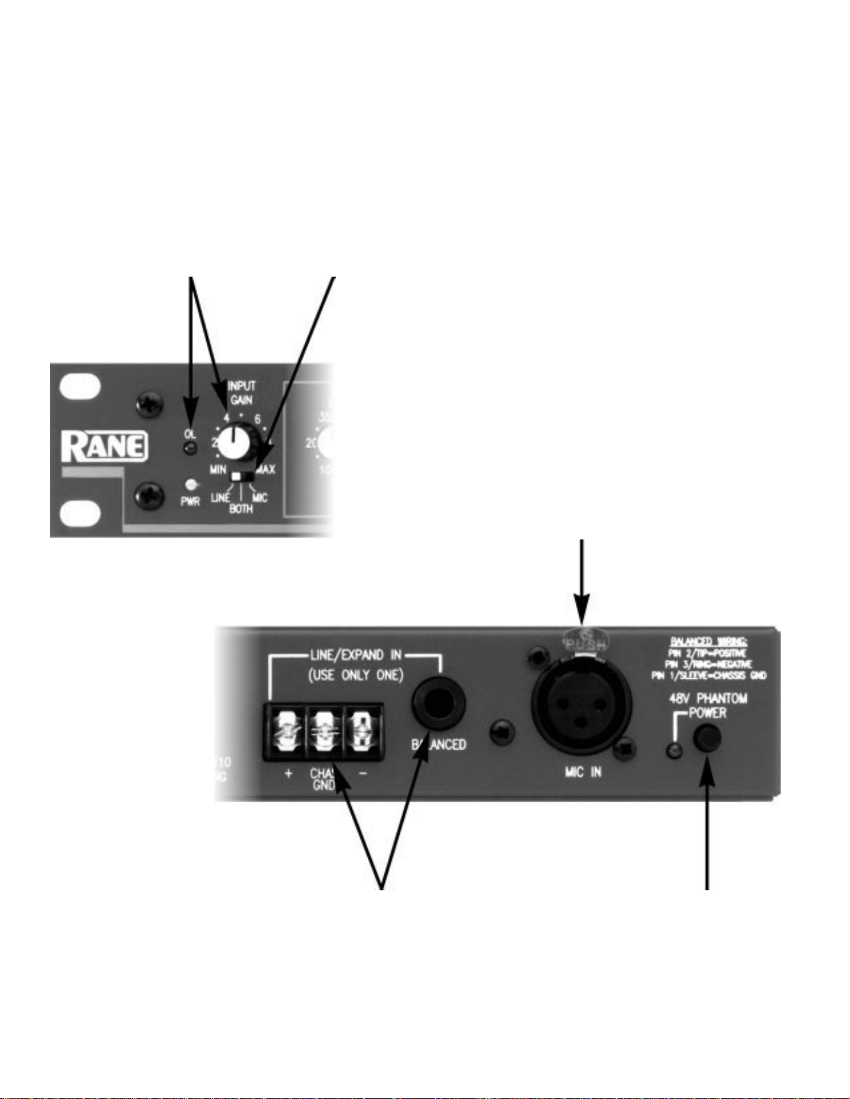
INPUT GAIN control
This control adjusts microphone
input level. Set this to make the
OL (Overload) LED flash occasionally. If the OL LED is on constantly, the level is too high—no
illumination means the level is
too low. It’s important to have
this gain stage set up properly to
maintain the best signal-to-noise
ratio.
LINE/BOTH/MIC switch
This three position switch allows
selection of which rear panel
input is active: line, mic, or a
sum of both inputs.
Input Section Rear Panel
MIC IN
This XLR accepts microphone
level inputs.
LINE/EXPAND IN
connectors
Use either the balanced/unbalanced ¼" TRS or the screw
terminals to connect a line level
input. Do not use both.
48V PHANTOM POWER
switch
This engages 48V phantom power
for condenser microphones. The
associated red LED indicates that
phantom power is on. Be sure the
mic can accept 48V phantom.
Page 3
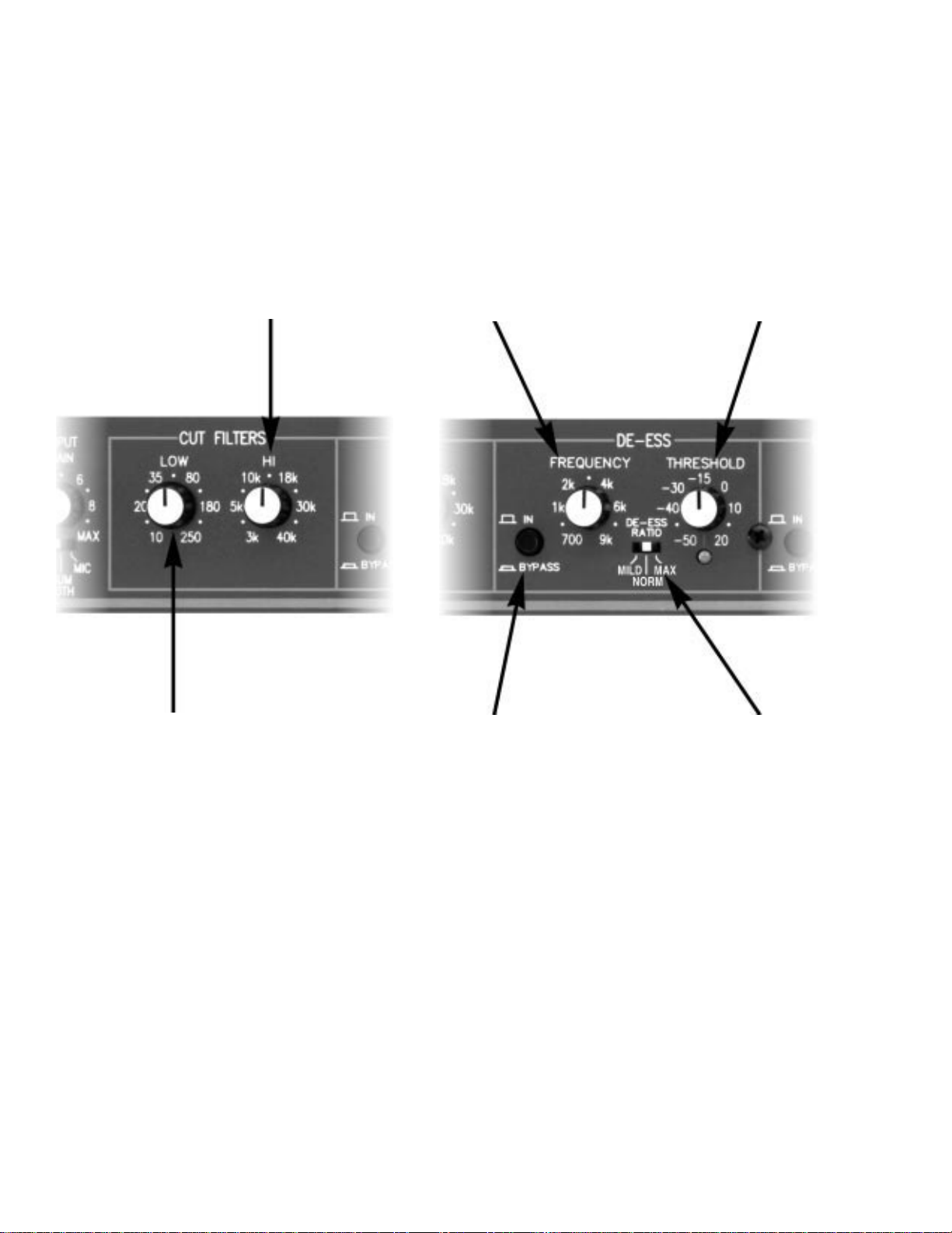
Cut Filters
De-esser
DE-ESS THRESHOLD
HI CUT FILTER
This control rolls the high frequencies off at a rate of 12 dB
per octave. The frequency designator (3 kHz to 40 kHz) is the
corner frequency at which the
high end starts to roll off. Turned
all the way clockwise, the high
cut filter is essentially out of the
circuit.
DE-ESS FREQUENCY
This control selects the upper
range of frequencies that the deesser circuit responds to. A
setting of 700 Hz is for extreme
de-essing, while 9 kHz provides
very light de-essing.
This control determines the level
in dBu that the upper frequencies (as set by the FREQUENCY
control) must exceed to activate
de-essing. A setting of -50 deesses everything, while at 20 no
de-essing occurs. The THRESHOLD
LED illuminates when the deesser threshold has been reached
and the de-esser is active.
LOW CUT FILTER
This control rolls the low frequencies off at a rate of 12 dB per
octave. The frequency designator
(10 Hz to 250 Hz) is the corner
frequency at which the low end
starts to roll off. Turned all the
way counterclockwise, the low
cut filter is essentially out of the
circuit.
BYPASS switch
This allows de-essing to be
bypassed for easy comparison
between de-essed and non-deessed signal.
DE-ESS RATIO switch
This sets the amont the sliding
band filter will “slide” for a given
amount of sibilance. The ratio
settings are adjustable from MILD
(a little de-essing), NORM (moderate de-essing), and MAX (heavy
de-essing).
Page 4

What is De-Essing?
In a nutshell, de-essing is nothing more than attenuation at
specific frequencies. Sibilance
(that annoying hissssing of “ess”
sounds that exhibits itself in
some peoples’ speech) manifests
itself as an increased level,
normally in the 3.5 kHz range.
However, this frequency may vary
from individual to individual,
hence the de-esser frequency
adjustment on the VP 12.
Large amounts of overall compression can actually accentuate
sibilant sounds. This not only
upsets the balance between high
and low frequency speech components, but can drive the sound
system into distortion.
Therefore, the best approach to
controlling sibilance is a circuit
that is adjustable to engage at
and above specific frequencies.
The characteristics of sibilance
demand a circuit with a fast
attack time and slow release time
to ensure a smooth inaudible
transition between the gainreducing state and the constantgain condition.
Through exhaustive testing of
currently available de-esser
circuits in other manufacturers’
products, Rane found that most
exhibit unwanted artifacts such
as common compressor “pumping” and “breathing”. Some
exhibit 180° phase errors as well
as uneven frequency responses
(as much as +3 dB) at the deesser corner frequency.
Deciding that there had to be a
better way to accomplish sibilance control, the Rane engineering team designed and implemented a totally new circuit
utilizing a revolutionary adaptive
servo controlled sliding band
circuit. Excellent buzz-words, but
in simple English this means that
instead of frequency dependent
compression, we designed a
sliding band filter that responds
quickly and quietly.
low pass filter
Amplitude (dB)
20 Hz 20 kHz
compression levels
Frequency (Hz)
The band pass filter, controlled
by the de-esser FREQUENCY
control, selects the frequencies
above which sibilance resides,
and since the filter is out of the
signal path and in the detector
path only, there are no summing
or gain errors. The voltage controlled 6 dB per octave sliding
band filter has an adaptive ratio
that allows a quick response, but
when it starts to attenuate the
unwanted sibilance, the response
slows down, providing a minimum of artifacts.
The graphs below visually demonstrate the new way versus the
old way.
+3 dB
sum error
high pass filter
o
180 out of phase
sibilance frequency
Other De-Esser Response
Amplitude (dB)
20 Hz
sibilance frequency
Frequency (Hz)
Rane De-Esser Response
20 kHz
Page 5

Gate/Expander & Compressor
GATE/EXPANDER
THRESHOLD
This control sets the point below
which the output of the VP 12 is
turned down or shut off, depending on the RATIO selected. The
associated yellow LED indicates
when the threshold has been
reached.
COMPRESSOR
THRESHOLD
This control sets the point above
which the gain is held in check.
The associated red LED indicates
when the threshold has been
reached.
COMPRESSOR RATIO
Determines by how much the
gain is held in check. Remember,
higher ratios mean the compressor works harder, essentially
turning it into a limiter. Ratios
are expressed in X:1. A 1:1 ratio
is no gain reduction, like being
bypassed. A ratio of 10:1 means
that for every 10 dB of signal over
the threshold point, only 1 dB
gets out—this is considered a
limiter. A straight limiter is
usually preset at 10:1 or higher; a
compressor has a variable ratio
that allows subtle compression to
heavy limiting.
BYPASS switch
This switch allows gate/expansion and compression to be
bypassed for easy comparison
between processed and nonprocessed signal.
GATE RATIO switch
This switch determines how
much the signal is turned down
when the gate activates. For
gating, effectively turn the signal
off with a low GATE/EXPANDER
THRESHOLD and high (3:1) GATE
RATIO. For downward expanding,
use a more moderate GATE/
EXPANDER THRESHOLD setting and
a low (1.5:1) GATE RATIO.
GAIN REDUCTION meter
This gives a visual indication of
how much compression is going
on. The metering is still active in
the bypass mode. This allows
adjustment of the compression
section “on the fly” while in
bypass to visually verify how
different settings will affect the
signal.
Page 6

Parametric Equalizers
FREQUENCY control
This selects the specific center
frequency to be affected. This
control works along with the
select switch below it to provide
full audio spectrum frequency
range for each band.
LEVEL control
This allows between +12 dB of
boost and -15 dB of cut at the
center frequency.
BW control
BW stands for “bandwidth”. This
allows selection of a skirt as
narrow as .03 octave (feedback
control) or as wide as 2.0 octaves
(broad tonal shaping) around the
center frequency.
BYPASS switch
This switch allows parametric
equalizers to be bypassed for easy
comparison between equalized
and non-equalized signal.
FREQUENCY select switch
This ingenious little three-position switch allows you to select
one of three frequency ranges,
allowing the FREQUENCY control
to cover the entire audio spectrum with greater resolution. The
“x0.1” setting allows frequencies
of 10 Hz to 200 Hz to be dialed
in. The “x1.0” setting provides the
100 Hz to 2 kHz frequencies
silkscreened on the front panel.
The “x10” setting provides the
frequencies of 1000 Hz (1 kHz) to
20 kHz.
BAND 2
The controls of this second
parametric are the same as those
found in BAND 1. Two bands
allow for two separate frequencies
to be modified. The two parametric bands are connected in series,
so simply setting the filters to the
same frequency can double the
amount of boost or cut. Total cut
for a single frequency can
amount to -30 dB!
Page 7

Output Section Front Panel
MAIN & AUX output
meters
These six segment meters show
the output levels. Note: If the rear
panel MAIN OUT LEVEL is switched
to MIC, the meter is no longer in
dBu, but gives visual indication
of available headroom.
Output Section Rear Panel
MAIN OUT LEVEL switch
This sets the output level for the
Main output to either LINE or MIC
level.
MAIN OUT
These XLR and screw terminals
are fully balanced, and may both
be used at the same time.
MAIN & AUX OUTPUT
LEVEL controls
This is a concentric rotary pot.
The small diameter capped knob
controls the main output, while
the large diameter knob controls
the aux output.
AUX OUT
These XLR and screw terminals
are also fully balanced, and may
both be used at the same time.
Page 8

Screw Terminal Patch Strip
This strip is configured from the factory with all functions operational in the same left-to-right order as
the front panel. Factory jumper locations are indicated by the arrows. This strip allows reconfiguring the
order of processing functions and/or wiring around unwanted functions. The SIDE CHAIN PATCH allows the
insertion of external processing.
Features and Benefits:
Feature: Line/Both/Mic Switch
Benefit: Allows summing of both mic and line
inputs. No other voice processor has this feature.
Feature: High and Low Cut Filters
Benefit: Allows both high and low ends to be rolled
off. Often with voice signal there is little or no audio
in these areas, and this affords greater signal-tonoise ratio.
Feature: Adaptive Ratio Sliding Band
De-esser Circuit.
Benefit: This totally new circuit design provides
more accurate de-essing with fewer artifacts and
more precise control than frequency dependent
compression.
Feature: Frequency Multiplier on
Parametric EQ.
Feature: Parametric bands wired in
series.
Benefit: Doubling up on a frequency in both bands
allows twice the boost and cut.
Feature: Main and Aux Outputs
Benefit: Allows signal to be sent to the stereo input
of the next device or to two different locations with
independent level control.
Feature: Main Out Level (Mic-Line)
Switch:
Benefit: Allows feeding a mic level signal to the mic
input of a console.
Feature: Screw Terminal Patch Strip
Benefit: Allows processing functions to be rearranged or bypassed.
Benefit: Allows each parametric band to cover 10
Hz to 20 kHz while maintaining precise control.
©Rane Corporation 10802 47th Ave. W., Mukilteo WA 98275-5098 TEL (206)355-6000 FAX (206)347-7757 WEB http://www.rane.com
520-494 APR96
 Loading...