

Rane VP 12 User Manual
OPERATORS MANUAL VP 12
QUICK START
Even if you don’t like to read manuals, read this part. We’ll
make it quick and painless. We promise.
Turn down (fully counterclockwise) the MIC INPUT GAIN
and both MAIN and AUX OUTPUT LEVEL controls. Set
the LOW CUT FILTER to 10 (fully CCW) and the HI CUT
FILTER to 40k (fully CW). Depress all BYPASS switches on
the front panel.
If you are using a mic, connect it to the MIC IN jack located
on the rear of the unit. If your mic requires phantom power,
press the rear panel 48V PHANTOM POWER switch. If you
are using a line level source (like the output of a wireless mic
receiver), connect its output to either the ¼" TRS jack or the
screw terminals located on the rear of the unit labeled LINE/
EXPAND IN. Leave all jumpers located on the long screw terminal patch strip in the original factory shipped position. ese
positions guarantee you access to all the features of the VP 12.
Connect the Outputs of the VP 12 to your mixer board or
recorder. e switch located directly next to the XLR MAIN
OUT jack converts the MAIN OUTs to either a MIC or LINE
level output, depending on your driving requirements. e AUX
OUT of the VP 12 is only line level.
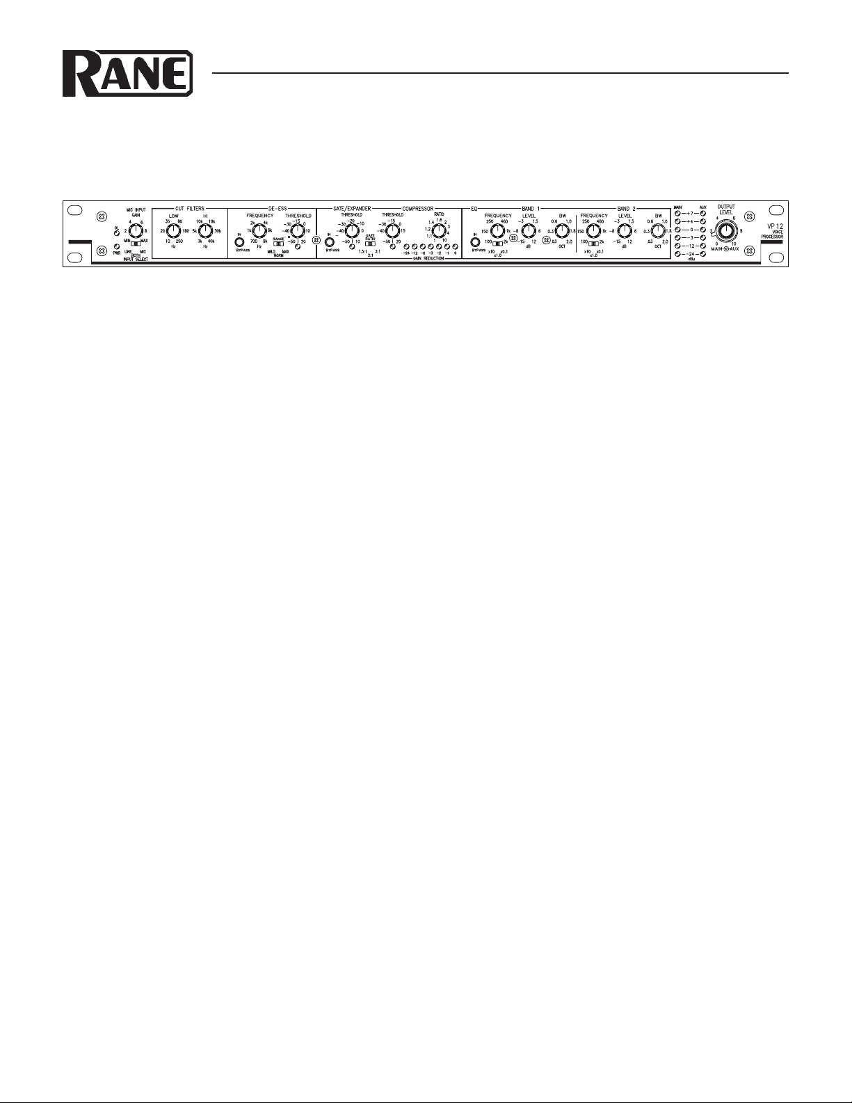
VOICE PROCESSOR
Plug the included power supply (see italics below) into the
VP 12. e yellow PWR LED will illuminate if all is well. Now
warn everyone else around, and yell into your mic the loudest
sound you expect during your session or performance. While
doing this adjust the INPUT GAIN control so that the loudest
sounds will occasionally illuminate the OL LED. If you are using the LINE IN, adjust the output level of the previous device
to occasionally illuminate the OL LED of the VP 12 when the
loudest signal you expect to hear is present.
Adjust the VP 12 OUTPUT LEVEL controls to match
the device you are driving. Now taking one processing section
at a time, release its BYPASS switch and adjust the processing
controls. Any number of processing sections may be IN or BY-
PASSED to isolate different parameters. For details on setting
these properly see OPER ATING INSTRUCTIONS on the last
two pages.
Never connect anything except an approved Rane power
supply to the thing that looks like a telephone jack on the rear
of the VP 12. is is an AC input and requires special attention if you do not have an operational power supply EXACTLY like the one originally packed with your unit.
WEAR PARTS: is product contains no wear parts.
Manual-1
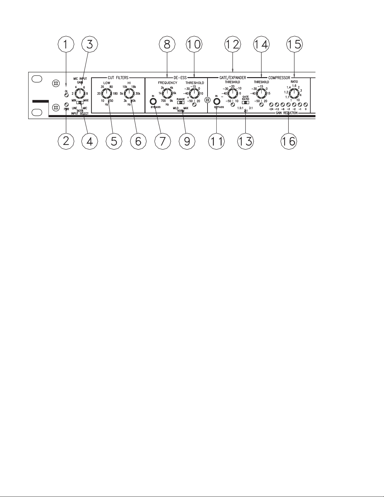
FRONT PANEL DESCRIPTION
1 OL (overload) indicator LED. Illuminates (red) any time the signal is within 4 dB of overloading. Five locations are monitored.
See the block diagram with the schematics elsewhere in this manual.
2 PWR (power) indicator LED. Illuminates (yellow) when power is connected. Use only an approved RANE AC remote supply
such as an RS 1 (included) or RAP 10.
3 MIC INPUT GAIN control. Increases mic input gain as it is rotated clockwise. It’s range is 15 dB of gain at full CCW rotation
to 60 dB at full CW rotation.
4 MIC INPUT SELECT switch. In the LINE position, the signal entering LINE/EXPAND IN is active. In the MIC position the
signal entering the MIC IN is active. In the BOTH position both LINE and MIC signals are summed together. Level matching
between LINE and MIC signals must be done externally in the SUM BOTH position.
5 LOW CUT filter. Defines the low cut-off frequency. In the full CCW position the LOW CUT filter is essentially out of the
signal path.
6 HI CUT filter. is control defines the high cut-off frequency. In the full CW position the HI CUT filter is essentially out of the
signal path.
7 DE-ESS BYPASS switch. When this switch is in the DE-ESS function of the VP 12 is not functional and the DE-ESS controls
will do nothing. DE-ESS is active in the out position.
8 DE-ESS FREQUENCY. is control determines the range of frequency that the DE-ESS circuit is sensitive to. In practice it
is best to set this to the highest frequency that will provide the amount of DE-ESSING you require and no lower. e lower the
frequency setting the less transparent the DE-ESSING function becomes.
9 DE-ESS RATIO. is three-position switch determines the rate at which the DE-ESS filter responds to expected sibilance. e
NORM setting is best for most situations.
0 DE-ESS THRESHOLD control and LED. is control sets the signal level in dBu above which the DE-ESS function becomes
active. When the LED is lit, the threshold has been exceeded and the DE-ESSER is doing its thing.
Manual-2
 Loading...