

Page 1
OPERATORS MANUAL Via 10
ETHERNET BRIDGE
Introduction
Normally, one would find our Quick Start at this
location. But to break with tradition and keep us all on our
toes, we thought we’d be different. After all, the Via 10 is
different in that it has no audio connections. Many Via 10
users employ the Via 10 to run Rane’s RW 232 devices
over a standard Ethernet LAN. Such users need only read
the Configuring the Via 10 & PC (page Manual-4) and the
RW 232 section under Hardware (page Manual-6) to get
rolling. Those who want the Quick Start need only think of
these two sections as the Quick Start. See, it’s not that
different.
This document is organized in four parts. Part one is a
short description of the front and rear panel controls found
on the Via 10 (page Manual-2). Part two is Configuring the
Via 10 & PC (page Manual-4) which explains what the Via
10 Config Utility does. It also reviews the computer setup that
is required so the computer can talk through the Via 10’s IP
(Internet Protocol) “language.” Part three goes over the
Hardware details of the Via 10’s I/O ports (page Manual-6).
Four sections are found: RS-232; RS-485; Versatile Input
Port (VIP); and the Versatile Output Port (VOP). OK, so VIP
and VOP should have been forever retired as cheesy splash
screens from the old Batman TV series. For those who watch
Dilbert, it is true that naming things like this is always the
hardest part of product development. Part four gets into
Microsoft’s ActiveX controls and how to use them to control
RW 232 and other parameters (page Manual-9). Part four also
contains the ActiveX Control details of the Via 10 and other
Rane-specific ActiveX controls for our computer-controllable
products.
WEAR PARTS: This product contains no wear parts.
Manual-1
Page 2

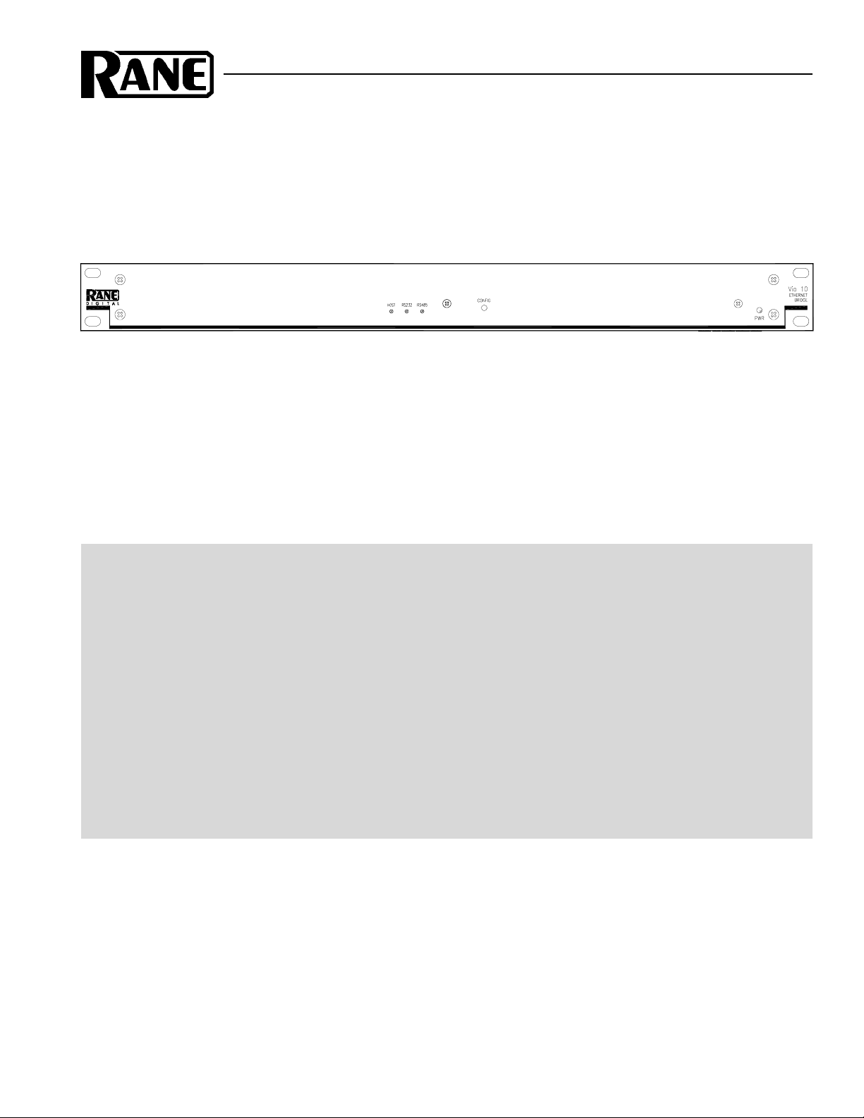
FRONT PANEL DESCRIPTION
햲 HOST indicator lights only when the Via 10’s internal host microprocessor “talks” (reads or writes) to the VIP or VOP.
햳 RS232 indicator illuminates when there is activity on the Via 10’s RS-232 port.
햴 RS485 indicator flashes when there is activity on the Via 10’s RS-485 port.
햵 CONFIG button is recessed, only used to set the Via 10’s IP address during initial setup. See Configuring the Via 10 & PC
on page Manual-4.
햶 PWR indicator lights when the Via 10 is powered. It flashes when in Via 10 CONFIG mode.
Manual-2
Page 3
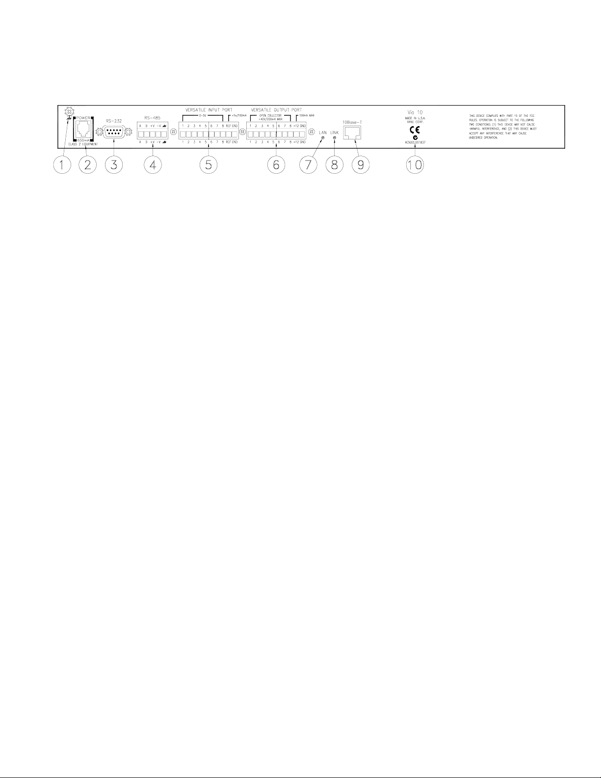
REAR PANEL DESCRIPTION
햲 Chassis ground screw & star washer. Since the Via 10 is powered from a remote AC power supply which does not carry
chassis ground through to the grounding pin of the AC cord, this screw is provided in case your system does not have
another earth grounding means. See the CHASSIS GROUNDING note below.
햳 POWER input connector. Use only a Rane RS 1, or other Remote AC power supply approved by Rane. This unit is
supplied with a remote power supply suitable for connection to this input jack. Consult the factory for a replacement or a
substitute. This unit’s power input is designed for an AC supply, delivering 18 volts, from a center-tapped transformer
capable of supplying at least the 650 mA of current demanded by this product. Using any other type of supply may damage
the unit, void the warranty or catapult the moon out of its orbit. See RaneNote 121 “Remote AC Power—An Idea Long
Overdue.”
햴 RS-232 port provides the communications data path between RS-232-based serial devices such as our RaneWare line of
audio products. Be sure the Via 10 is configured properly for your serial application.
햵 RS-485 port provides the communications data path between RS-485-based serial devices such as Rane’s SR 1L Smart
Remote control which is an accessory for the SRM 66 Splitter Router Mixer. Be sure the Via 10 is configured properly for
your cereal application. (OK, it’s a bad joke.)
햶 Versatile Input Port (VIP) is an exquisitely programmable logic and/or A/D input port for use with external switches,
potentiometers or any zero to five volt instrumentation device. Up to eight input devices in any variety are supported. See
the Hardware VIP section on page Manual-7 for further details.
햷 Versatile Output Port (VOP) is a splendidly programmable open-collector logic output port for use with external indicator
lamps, LEDs, relays or any ground referenced external device. Up to eight output ports support any assortment of output
devices. See the Hardware VOP section on Manual-8 for further details.
햸 LAN indicator flashes when the Via 10 is connected to a 10Base-T network.
햹 LINK indicator quickly glows when any packet is present on the network. Yes, this means any packet, including packets
that are or are not intended for the Via 10.
햺 10Base-T Ethernet jack connects the Via 10 with a standard RJ-45 connector to either a PC’s Ethernet card or a standard
HUB or concentrator in a network.
햻 The Australian C-Tick mark does nothing when pressed, should not be licked and indicates that the Via 10 is safe (in the
UL sense) to use down under.
CHASSIS GROUNDING
Units like the Via 10 with outboard power supplies do not
earth ground the chassis through the line cord. This chassis
connection is critical and in most installations, required by
law. Many ground this point to an amplifier chassis ground,
grounded rack rails or directly to the grounding screw on a
grounded AC outlet cover by means of a wire secured on both
ends with star washers to guarantee proper contact.
Please refer to RaneNote 110, “Sound System Interconnection” (available at www.rane.com) for further information
on system grounding.
Manual-3
Page 4

Configuring the Via 10 & PC
The disks that ship with the Via 10 contain several tools:
1) The VIACONFIG utility for initializing the Via 10.
2) Rane ActiveX controls for the four Via 10 hardware ports
plus controls for Rane’s RW 232, SRM 66 and SR 1L
products. These ActiveX controls are registered (i.e.,
copied to your computer) during the installation process.
3) The VIPVOP utility for testing the VIP and VOP interfaces.
Example HTML (HyperText Markup Language) files to
assist system programmers are available as links from Rane’s
Via 10 web page at http://www.rane.com/via10.htm.
Three steps are required to configure the computer and
Via 10 for typical applications. Step one is to design the
network and determine its needs; for example, the number of
network devices (also called DTEs [Data Terminal Equip-
ment]). In step two you must determine the IP addresses you
want to use for each computer in the system. You’ll also need
to verify that the computer is configured properly to speak to
the Via 10 and the rest of the network. Step three is running
the Via 10 Configuration Utility (VIACONFIG) to set the IP
address and RS-232 and RS-485 port baud rates and parities,
among other things.
I. Network design. First design your Ethernet network. If
you only have one computer and one Via 10, you’ll need a
CAT 5 (Category 5) crossover cable, not a standard ethernet
cable…and you thought crossovers only split audio signals
into highs and lows. A crossover cable is a CAT 5 cable wired
so the transmit pair at one end is connected to the receive pair
at the other. If you have more than two Ethernet devices –
i.e., more than one computer or more than one Via 10 or other
Ethernet device – you’ll need a hub (also called a concentra-
tor or repeater) to connect them. There are many sources for
help on designing Ethernet-based networks, such as the Rane
Via 10 web page. It includes links to some very helpful web
sites with more information on Ethernet and network design
than you’d ever need to know: www.rane.com/via10.htm.
Also, see RaneNote 144, “Emerging Standards for Network
Audio System Control” for background on how all this
network talk fits into the audio industry in the first place.
II. Computer IP set up. The computer used with the Via
10 must be set for network operation to allow it to speak to
the Via 10 using TCP/IP protocol. (TCP stands for Transmission Control Protocol.) If your computer is already set up for
network operation you can skip to the next section.
Setting up a Windows 95/98 PC for network communications:
Note: As you go through the following procedure your
computer tells you on more than one occasion that it needs to
reboot before changes take effect. Just go along with it when
this happens. Yeah, it’s a big waste of time but this is an
owner’s manual, not an editorial page – so just do it, OK?
1. Insure you have a functional Ethernet adapter (NIC or
Network Interface Card) installed in the PC. If installed, its
operation may be checked by right clicking on ‘My
Computer’ followed by a left-click on the selection
‘Properties’ and again a left-click on the ‘Device Man-
ager’ tab of the ‘System Properties’ dialog box. Click on
the plus (+) sign to the left of ‘Network Adapters’ to view
the configured adapters. A malfunctioning adapter is
indicated by either a yellow question mark or a red ‘X’.
There are several troubleshooting aids available in Windows Help to assist you in making the network adapter
functional.
2. Once you have a correctly operating Ethernet adapter,
TCP/IP is easy to configure. To begin, open ‘My Com-
puter’ or ‘Start > Settings,’ then ‘Control Panel >
Network’. The ‘Configuration’ tab shows a list of config-
ured devices, such as your network card and possibly dialup networking. Below these is a list of network protocols
previously configured for the system. If TCP/IP has been
configured and bound to the Ethernet adapter, you will see
an entry resembling ‘TCP/IP -> NameOfAdapter Pnp
LAN Adapter.’ If this shows on the list, skip to step 4. If
it’s not there, go through step 3 first.
3. To add TCP/IP to the LAN Adapter, click the ‘Add’ button
in the Network dialog. A list of network component types
displays. Choose ‘Protocol,’ then ‘Add’. A list of manufacturers displays. Click on ‘Microsoft’, then ‘TCP/IP’ in
the right-hand window, then ‘OK’.
4. To be a part of a TCP/IP network, your computer (and each
network device including the Via 10) needs a unique IP
address of its own. If not already open, open ‘Settings >
Control Panels > Network.’ Highlight the ‘TCP/IP ->
NameOfAdapter PnP LAN Adapter’ by clicking on it.
Then choose ‘Properties > IP Address.’ Click on the
‘Specify an IP address’ option. If your computer is part of
an existing network, you must now obtain a valid address
from the network administrator—if you have one. If not,
you may use an address out of the internationally accepted
private network block of addresses, which is
192.168.nnn.nnn where nnn represents any number
between 0 and 255. A good choice might be
192.168.100.100 just because it’s easy to remember if you
ever need to know it again. The ‘Subnet Mask’ should be
set to 255.255.0.0 for most installations. These two
settings allow a network with addresses in the range of
192.168.0.0 through 192.168.255.255. Click the ‘OK’
buttons as many times as they appear to extinguish all the
network setup dialog boxes.
Note: Once you’ve set networking on a Win95/98 computer, you’ll notice it wants a user name and optional password each time it boots. To eliminate this nuisance, go back
in to Control Panel > Network and change the ‘Primary
Network Logon’ selection from ‘Client for Microsoft
Networks’ to ‘Windows Logon’ then click ‘OK’ again. Oh,
and guess what? Your computer will want to be rebooted
again for the change to take effect. Good news, though, it
won’t ask for a user name and password this time.
III. Via 10 Config Utility. The Via 10 Config Utility
(VIACONFIG) ships on floppy disk with each Via 10 and can
also be found at www.rane.com/via10.htm.
Manual-4
Page 5
VIACONFIG has several purposes:
a) It allows setup of the Via 10’s IP address and serial port
baud rate and parity settings.
b) It verifies Via 10 operation with the computer.
c) It allows Via 10 firmware updates over the LAN.
d) It provides a debug mode to test the Via 10 serial ports
using Windows’ HyperTerminal or a similar terminal
program. (A separate VIPVOP application tests the Via
10’s VIP and VOP interfaces.) VIACONFIG is also the
place to look if you need to find out the MAC (Media
Access Control) address of a Via 10.
By default, VIACONFIG places its files in a folder called
C:\Program Files\Rane Corporation\Via 10 Utilities. Also,
shortcuts to VIACONFIG and VIPVOP are placed in
C:\Windows\Start Menu\Programs\RaneWare. This
provides access to Via 10 files through Window’s Start
Menu.
Via 10 MAC address. Every Ethernet device in the
world, including each Via 10, contains a unique MAC
address. The IEEE doles out MAC addresses to the universe
and each Via 10 is loaded with a unique MAC address at
Rane’s factory before shipping. (Otherwise, we couldn’t test
them on a LAN before shipping…get it?) When you run
VIACONFIG with a Via 10 (in config mode) connected, the
MAC address for the connected device is displayed at the top.
MAC addresses are in hexadecimal and are 6 bytes long—for
example: 00:60:2B:02:3F:FF. For the curious, this is an
address somewhere around 4.13 X 10⁹. There are many more
addresses available for the future. Rane offers substantial
discounts for the first system ordered where this number of
MAC addresses is insufficient.
Setting the Via 10 IP Address. Each Via 10 requires a
unique IP address so the network knows what “phone
number” to use to talk to each Via 10. See step #4 under
Computer IP Setup (previous page) to determine valid IP
addresses for the Via 10(s). Using the proper IP address is
important because of potential (or future) conflicts with other
network traffic. Also, depending on what IP Address and
Subnet Mask you’ve used on the PC(s) involved, certain Via
10 IP addresses will be invalid and not work. If you’ve set the
PC with IP address 192.168.0.0 and Subnet Mask
255.255.0.0, a good start for Via 10 IP Addresses might be
192.168.100.100. Add 1 to the final number for subsequent
Via 10 IP addresses.
1. Install the Via 10 Config Utility by inserting the disk in the
computer’s floppy drive (or download it from our web site
www.rane.com), then select Run from Windows’ Start
menu and Browse to the floppy drive (or file) and doubleclick SETUP to run the VIACONFIG install routine.
2. If you power up a new Via 10, it comes up in config mode
which is indicated by a flashing POWER LED. If it’s not
already, place the Via 10 in config mode by unplugging the
power, then, hold in the Via 10’s front panel CONFIG
button with a pen or small implement and plug in the
power to the Via 10. The POWER LED flashes indicating
config mode.
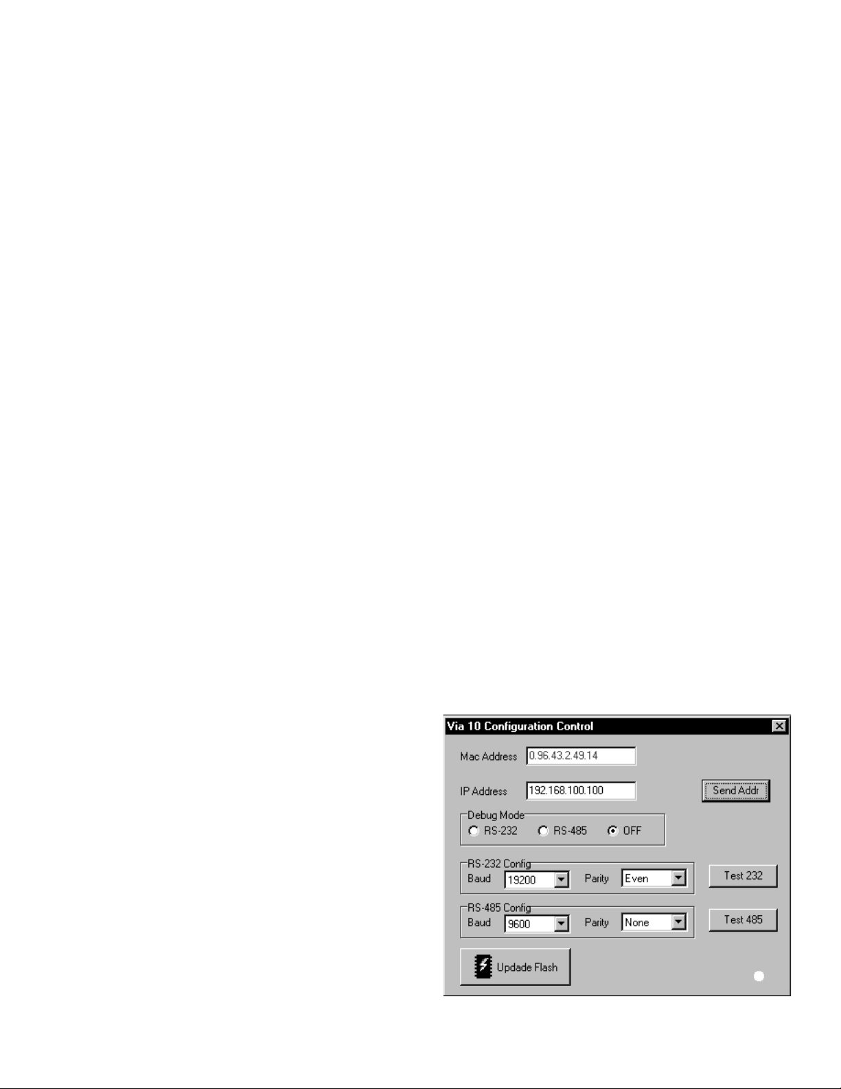
3. Run VIACONFIG, then type in the proper IP address for
the connected Via 10 in the IP address field and click the
Send Addr button. When you run VIACONFIG and have a
powered Via 10 in config mode connected to the network,
the indicator at the bottom right of the VIACONFIG screen
turns green indicating communication with the Via 10. If
this indicator is yellow, it means that the Via 10 is successfully receiving network packets, but the Via 10 IP address
you’ve input is in conflict with the valid IP addresses set
on the PC. If this indicator is grayed out, verify that the Via
10 is in CONFIG mode. To debug a non-communicating
Via 10, check that the computer and any hubs in use are set
and operating properly and be sure you have the proper
cables. Most non-communicating Via 10’s are caused by
improper network settings on the various components.
Note: Be sure you use a valid IP address obtained either
from a network administrator (many won’t have one of these
nerds) or from using one of the IP numbers discussed above
under Computer IP Setup, step #4. A good reason to always
obey these “Standard Committee-driven” IP address rules
includes future network upgrades and their disposition which
(although unforeseen and maybe inconceivable now) might
do rather strange things when installed a year or three from
now.
Once the Via 10 IP address is set properly, the other fields
in the VIACONFIG screen are viewable and show the current
Via 10 settings such as MAC address and RS-232 and RS-485
Baud and Parity values.
4. Unplug the Via 10 and plug it back in again to complete
the Via 10 IP Address setup. The Power LED should not
flash once power is restored. If it does, see steps 2 and 3
again.
RS-232 & RS-485 Baud and Parity settings for the Via
10 ports are shown on the VIACONFIG screen. The default
RS-232 baud rate is 19200, default parity, Even. If your
application requires different settings, select the new settings
from the pull-down menus provided. To send these settings to
the Via 10, you must hit the Test 232 and Test 485 buttons.
VIACONFIG screen
Manual-5
Page 6
Test the Via 10’s RS-232 port (optional) by running
Windows’ HyperTerminal program found under Start >
Programs > Accessories > HyperTerminal. With
HyperTerminal running and the Via 10’s RS-232 port hooked
up to the computer’s RS-232 port using (unfortunately) a null
modem cable, click the Test 232 button on the Via 10
Configuration screen. If working properly, the message: “232
Test” shows in the HyperTerminal screen. This verifies that
the baud and parity settings are correct.
Note: A null modem cable is required for this test because
the Via 10’s RS-232 port must “look like” a terminal to the
computer.
Testing the Via 10’s RS-485
port (optional) takes one extra
piece of hardware. The Rane DSC 1
accessory is an RS-485 to RS-232
converter that is useful for this test.
Run Windows’ HyperTerminal
program found under ‘Start >
Programs > Accessories >
HyperTerminal.’ With
HyperTerminal running and the Via
10’s RS-485 port hooked up
through an RS-485 (or RS-422) to
RS-232 converter using a null
modem cable hooked to the computer’s RS-232 port, hit the
Test 485 button on the Via 10 Configuration screen. If
working properly, the message: ‘485 Test’ shows in the
HyperTerminal screen.
Note: A null modem cable is required for this test because
the Via 10’s RS-485 port must “look like” a terminal to the
computer.
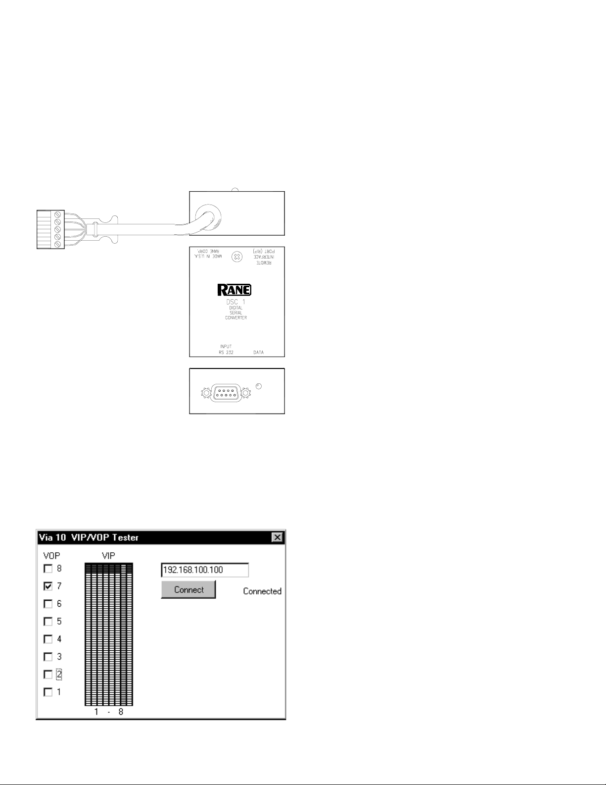
Test the VIP & VOP ports (optional) by looping them
together so data sent out of the VOP appears on the VIP.
Connect VOP 1 to VIP 1, VOP 2 to VIP 2, etc. Then run the
VIPVOP utility. The default location after installation is:
C:\Program Files\Rane Corporation\VIPVOP. In the box in
the upper right corner of the VIPVOP screen, type in the
proper IP address of the Via 10 you are testing. Then click the
Connect button; the green LED on the VIPVOP screen lights
when connection is successful.
VIPVOP displays 8 VOP check boxes down the left side;
when checked, the corresponding Via 10 VOP pin is pulled
low (0 volts/ground). When unchecked, the corresponding
VOP pin is pulled high (+5 VDC). Since the VOP pins were
previously connected directly to the corresponding VIP pins,
any changes to the VOP check boxes should immediately
show up on the VIP meters in the center of the VIPVOP
screen. VIP pin 1 is the left-most meter, then pin 2, 3, et
cetera, with VIP pin 8 on the far right. Connect a potentiometer to the VIP to vary the voltage and display the corresponding meter reading on the vipvop screen.
Hardware
This section discusses each of the Via 10 hardware ports.
As the title suggests, here you’ll find the hardware details for
each. Software details as well as applications are found in –
you guessed it – the Software and Applications section on
page Manual-8.
Hardware 1: RS-232 & the RW 232
RS-232 with Rane RW 232. The RS-232 port on the Via
10 can be hooked directly to the RW 232 Input port on any
Rane RW 232 device allowing extended communication
distances up to 305 feet (100 meters) over a standard 10BaseT Ethernet LAN. ActiveX controls for commonly controlled
parameters on the following Rane products are accessible
using any ActiveX capable software development tool: RPE
228d, RPM 26v, ECB 62, ECM 64, RPD 1. (See Applications
Using ActiveX on page Manual-10 for software and control
details for these products.) In English what this means is that
through a little bit of software know-how, one can, for
example, draw a slider on a web page, then link the slider’s
operation to the Master Output Level control on the Rane
RPM 26v. But, since this is the Hardware section of the
Manual, we’re a bit premature in even mentioning software
here.
The default settings of the Via 10’s RS-232 port support
RW 232 communications. If RW 232 devices are being used
with the Via 10 RS-232 port, the shipped baud and parity
settings of the RS-232 port need not be changed. Just in case,
the default settings are listed below. Only 8-bit wide words
are supported—no 7-bit words.
Manual-6
Via 10 Default RS-232 Communications Settings
(required for RW 232 use)
Baud Parity Start bit Stop bit RS-232 cable length
19200 Even 1 (always) 1 (always) 50 feet max
VIPVOP screen
Page 7

RaneWare RW 232 Ethernet operation. Run RaneWare
(2.10 or higher) and from the System menu, select System
Setup. In the Connection box, select the Via 10 (Ethernet)
radio button so RW 232 commands will be sent out of the
Ethernet port (rather than out the PC’s RS-232 COM port nor
out the computer’s modem and phone line to a far end modem
and Rane’s RPD 1). Make sure to type the proper Via 10 IP
address for the RaneWare RW 232 device(s) you wish to
control over the network. Each Via 10 can accept up to 16
RW 232 devices in any variety connected to its RS-232 port.
To address more RW 232 devices, use additional Via 10s.
Generic RS-232 use. RS-232 based serial devices can
transport their data through the Via 10 as long as the Via 10’s
RS-232 port is configured properly. The default settings for
the Via 10 RS-232 port are shown above. Supported ranges
for RS-232 communications can be found in the VIACONFIG
utility. The pull down fields display all supported settings.
For detailed RS-232 port specifications, see the Data Sheet
section of this Manual.
Standard RS-232/DB-9 wiring for Tx and Rx connections
are provided. The maximum cable length supported by RS232 is still 50 feet (15 meters); this assumes good quality,
CAT 5 cable.
A variety of external means are available to lengthen the
50 feet limitation by using RS-232 to RS-422 or RS-485
converter devices. These can be sourced from a variety of
manufacturers (but not Rane – we can’t make everything,
where would we put it? [OK, this is a Steven Wright joke, but
a good one]). At this point, we’re compelled to ask: doesn’t it
seem strange to have to mention such devices when your
system already includes 100 meter-capable Ethernet for
control?
Hardware 2: RS-485, the Rane SR 1L and SRM 66
SR 1L Use. This Rane accessory is a generic RS-485
device. Though an accessory for the Rane SRM 66 Splitter
Router Mixer, SR 1L’s can be used independently for a
variety of applications. See Software and Applications on
page Manual-8.
Up to seven SR 1L Smart Remotes can be wired directly
to the Via 10 RS-485 port in any combination of daisy chain
or star configuration. Use CAT 5 cable (two twisted pairs plus
a shield) and double check the wiring since this is often the
cause of baldness (i.e., pulling our collective hair out debug-
ging problems). Only the most distant SR 1L connected to the
Via 10 should have its RT switch ON, which connects a 150
ohm terminating resistor.
SRM 66 Use. The SRM 66 contains an RS-485 port
(called RIP for Remote Interface Port) which may be wired to
the Via 10’s RS-485 port for SRM 66 control over a LAN;
however, you cannot connect both an SRM 66 and SR 1L
remote(s) to the same Via 10—one device per RS-485 port.
Do not connect the V+ terminals together—connect A to A, B
to B, V– to V– and shield to shield.
RS-485 remote power. The Via 10’s RS-485 port
includes a low current, 8 VDC supply which is required for
SR 1L operation, but can be used for powering other low
power peripheral devices. The data sheet (in this booklet) lists
the specifications for this small power source, including its
current capabilities.
Generic RS-485 Use. Use CAT 5 cable for connection to
the RS-485 port. The balanced data connections can drive up
to 100 meters of cable when properly terminated with 150
ohms to obey the standard and ensure trouble-free operation.
Hardware 3: Versatile Input Port (VIP)
The VIP provides the perfect place to connect memory
recall switches, potentiometers, temperature sensors and other
instrumentation and/or logic devices. Each of the eight inputs
accepts 0 to 5 VDC and includes a true 8-bit A-to-D converter
providing 256 steps; (it’s actually a 10-bit converter that is
rounded to an 8-bit word length). You can therefore use each
of the eight VIPs as independently programmable comparators, ratiometric controls or instrumentation inputs. A currentlimited (100 mA max) internal voltage reference of 5 volts
(Vref) is supplied. Each port includes a 100k ohm pull-up
resistor to Vref and a 2
nd
-order, 15 Hz Butterworth low pass
averaging filter. Any range of potentiometer values and tapers
can be used as long as the 100 mA current limitation is not
exceeded. Either momentary or position-sensitive switches
can be used; use whatever is appropriate or easiest for your
application and its software setup requirements. Any instrumentation output with a 0 to 5 VDC range can be used with
the VIP. The VIP update rate is dominated by the network
transmission speed and is read each time the VIP data is
requested using the Via10VIPX ActiveX control (see page
Manual-9).
SR 1L Smart Digital Remote Control
INTERNAL REFERENCE
+5VDC (100mA)
TO HOST CONTROLLER
OCTAL 10 BIT A/D
REF
12345678
VIP (Versatile Input Port)
INPUT BUFFER
(0 to 5 volts DC)
Manual-7
Page 8

Hardware 4: Versatile Output Port (VOP)
The VOP provides an impeccable place to connect
indicators (LEDs, small lamps), relays and/or other logic
inputs. Each of the eight open collector outputs are independently programmable using the Via10VOPX ActiveX control.
Use each of the eight VOPs to independently drive indicators
or relays. Current on each of the eight open collector ports is
limited to 100 mA maximum when all 8 ports are driven; 200
mA maximum when 4 ports are driven. The VOP’s internal
12 VDC supply pin is limited to 100 mA maximum. Each
open collector VOP output includes a clamping diode for
switching inductive loads. Any combination of lamps, LEDs,
relays and logic input ports can be used as long as the 100
mA (8 driven) current limitation is not exceeded. So choose
your parts wisely. External power supplies may be necessary
when using larger current capacity relays that require more
than the 12 VDC/100 mA maximum allowed by the VOP. Up
to a 40 volt external power supply can be used with the VOP
as long as the external supply is ground referenced (i.e.,
connected) to the VOP GND pin. The VOP update rate is
dominated by the network transmission speed and is updated
each time the VOP data is renewed or changed using the
Via10VOPX ActiveX control.
VOP
= | MAX
+12
1
GND
RELAY
LOGIC
COIL
INPUT LAMP LED
OR OR OR
EXTERNAL
POWER
SUPPLY
+V (VP TO 40 VOLTS)
GND
12 VOLTS OR OR OR
100 mA= | MAX
8 PORTS DRIVEN: 100 mA
4 PORTS DRIVEN: 200 mA
GND
PORT 1 SHOWN, 2 THROUGH 8 THE SAME
VOP (Versatile Output Port)
Manual-8
Software and Applications
ActiveX and Software issues
ActiveX controls (defined in the next section) are of
concern to the pro audio community. This technology allows
designers of computer-controlled sound systems to create
common front-end software control panels that operate
different manufacturers’ units, without having to know
anything about their internal code or algorithms. This is
powerful. Once more manufacturers jump on the ActiveX
bandwagon, systems designers will no longer be limited by
the products offered by a single, platform-specific (i.e., closed
architecture) manufacturer. Each ActiveX control is made up
of Properties and Events. ActiveX control Properties are
values associated with the control which might include such
things as level settings, mute condition and meter readings.
ActiveX control Events tell the computer something significant has happened, such as a switch closure or clip detection.
ActiveX allows the manufacturer to create an object (a piece
of software code) which fully describes a device, while hiding
the implementation details such as protocol from the programmer. By hiding the communication details, there is no
longer a need for different manufacturers’ devices to agree on
protocol. This lack of a protocol standard means that cooperation between manufacturers is not required. It allows each
manufacturer to choose the best protocol for their devices.
For example, no longer would you need to know that the
th
17
byte of a 32-byte status message meant that the unit’s
second output channel was muted. With an ActiveX control,
you might simply refer to the device’s output 2 mute status as
“Device1.Out2Mute”.
What is ActiveX anyway? ActiveX is a Microsoft
developed software technology released in 1996. ActiveX,
formerly called OLE (Object Linking and Embedding), is
loosely based on the Component Object Model (COM), but
provides substantially different services to developers. At this
point, you might think: WHAT!?^* But keep reading! An
ActiveX control is a unit of executable code (such as an .EXE
file) that follows the Active X specification for providing
software objects. This technology allows programmers to
assemble reusable software controls into applications and
services. However, software development using ActiveX
technology should not be confused with Object-Oriented
Programming (OOP). OOP is concerned with creating
objects, while ActiveX is concerned with making objects
work together. Simply stated, ActiveX is a technology that
lets a program (the ActiveX control) interact with other
programs over a network (e.g., the Internet or Ethernet),
regardless of the language in which they were written.
ActiveX controls can do similar things as Java, but they are
quite different. Java is a programming language, while
ActiveX controls can be written in any language (e.g., Visual
Basic, C, C++, even Java). Also, ActiveX runs in a variety of
applications, while Java and Javascript usually run only in
Web browsers.
ActiveX controls can be used in web pages and within
visual programming languages such as Delphi, Power
Builder, Visual Basic and even in tools such as Lab View.
In English, for our pro audio applications, objects are the
Page 9

sliders, buttons, indicators and other graphical screen entities.
The objects have properties such as slider position and slider
range and on or off for buttons and indicators, etc. Once the
screen objects are chosen and placed, ActiveX controls can
then be used to link to the object’s properties to other
ActiveX controls. Thus, allowing linking a slider to the
ActiveX control for a level control so moving the level
control graphic subsequently varies the audio level.
Implementing ActiveX controls. An example might help
clear this up. A few assumptions are that a computer is used
to control an audio system over a 10Base-T Ethernet network
and that something on the computer’s screen controls some
function of the system. The basic idea is to place controls on
the computer screen and link them, using ActiveX, to a
parameter in the system. What’s important here is that only
the controls required by the computer’s end user need be
displayed. Additionally, more detailed interfaces (hidden or
password-protected web pages) can then be created to provide
any level of system parameter access desirable—from
complete system control, to a lone system power button or
anything in-between. No longer are systems limited to the
number of security levels provided by vendor’s software, nor
are you limited to controlling a single system parameter per
screen control. For example, you can link multiple ActiveX
controls to a single screen object, thus adjusting EQ level
simultaneously with master level control and limiter threshold. You can also program actions when certain events occur,
such as triggering audio playback or turning a system off at a
certain time or adjusting delay time as the temperature
changes.
Via 10 ActiveX Example. The short version of this
procedure is: insert a Via 10 ActiveX control in your web
page, set the control’s Properties as needed; assign a button
(or scroll bar) to the ActiveX control and set its Properties;
then use Microsoft’s Script Wizard to link the button’s Events
to Via 10 ActiveX parameters or link other Events and
Actions if needed for your application.
Important note: Even though Via 10 ActiveX controls must
be inserted in each web page where Via 10 controls are
needed, the Via 10 controls that are displayed in FrontPage
2000’s Normal window are
Internet Explorer or in the Preview window in FrontPage
2000.
The James A. Michener version of these examples is
found on our web site. [This is the extra added advantage of
receiving an early Via 10 – the Manual is 99.8 percent done.
The 0.2% is on our web site.] Go to www.rane.com/via10.htm
for other future downloadable updates such as sample HTML
pages and additional ActiveX controls.
not visible when viewed in
Microsoft FrontPage 2000 ActiveX example. Many use
Microsoft’s FrontPage 2000 to create user interface web
pages for computer-controlled systems. These web pages may
or may not be accessible over the Internet. The examples
found on Rane’s web site will review the basic FrontPage
2000 procedures to link screen controls to ActiveX controls.
A second example illustrates how to use Events, such as
clipping, to program a hands-off script to turn a level down.
Once you master these two concepts, using FrontPage with
ActiveX provides literally an infinite number of programming
possibilities. More information about the Via 10’s I/O port
ActiveX controls and the ActiveX controls for Rane’s RW
232 devices is found in the sections below.
Manual-9
Page 10

Applications using ActiveX
Via 10 ActiveX Controls. Each Via 10 hardware port has
an associated ActiveX control to allow programmable access
to the data entering or leaving a given port. This manual has
previously suggested many applications for these ports. They
are summarized below.
Via 10 RS-232 port Applications:
• Extend the communications distance of RaneWare RW
232 devices allowing RaneWare use over 10Base-T
Ethernet networks. Keep in mind that many stacks of RW
232 equipment can be controlled from a single location. Up
to sixteen RW 232 devices can be used with each Via 10.
And multiple Via 10 devices can exist on the same
Ethernet network.
• Use on-screen meters to indicate the real time (or at least
close to real “network” time) levels of RW 232 devices.
For example, place six multi-segment meters on the
computer screen and link them to the six output meters
found on the RPM 26v. Place an RPM 26v Master Level
Control slider next to the meters as a system level slider.
Link this same screen slider to multiple RPM 26v devices
as well as the low shelf and high shelf EQ controls of all
RPM 26v input PEQ blocks thus creating a customized
loudness compensation control.
• Transport any RS-232 data over 10Base-T Ethernet. A
variety of baud and parity settings are supported and
ActiveX controls can actively and automatically change the
RS-232 port settings allowing a wide variety of RS-232
data.
Via 10 RS-485 port Applications:
• The RS-485 port interfaces directly with the Rane SRM 66
and the SR 1L. Link input routing screen controls to the
SRM 66 matrix mix cross-points (I/O routing), include
level controls next to each output for on-screen level
adjustments. In another Via 10 on the same network, use
up to seven SR 1L remote devices and link them to seven
different RPE 228d equalizer output level controls—one
per zone.
• Any RS-485 data can be transported via Ethernet 10BaseT as long as the Via 10 ports are configured with the
proper baud and parity settings.
system parameter – all automatically and simultaneously!
• Use the position of a potentiometer to recall parameter
values, adjust level settings, change an EQ curve, delay
time and display the pot’s position on a computer screen.
Link a temperature sensor’s value to adjust the delay times
of a speaker stack. Get really picky and adjust delay time
for humidity too. Use a wind sensor to actively rotate your
speaker stack to compensate for sudden wind shear at your
local hurricane music festival. (Don’t laugh, this works!)
VOP Applications
• Connect indicators (LEDs, small lamps), relays and/or
other logic inputs to the VOP to allow computer screen
controls to correspond to the real world indicators and
relays required in computer-controlled systems. Small
lamps and/or LEDs can be used as indicators for a wide
variety of applications: indicate current memory, signal
present or clip indicators, system on indication, etc. Relays
driven from the VOP can perform a variety of jobs – power
other devices, turn on or off other components in the
system, open doors, unlock bank safes, turn on lights,
lower projector screens, close the curtains, etc. Turn on
your water sprinkler system from your Internet home page
or better yet, connect a moisture sensor to the VIP port and
automatically water your lawn according to the precipitation in your ground. Link your cell phone messaging
system to heat up your hot tub before you get home from a
restaurant. Drive the logic input ports of non-networked
system devices to alter system parameters thus allowing
non-Ethernet ready devices to be integrated into networked
systems.
Find detailed applications and example HTML files on our
web site. Also on our web site will be newly published
ActiveX controls for Rane products as they become available.
Put a bookmark at www.rane.com/via10.htm.
VIP Applications
• Connect memory recall switches, potentiometers, temperature sensors & other instrumentation and/or logic outputs
to the Versatile Input Port. Third-party software like
FrontPage, C++, Delphi or Lab View allow programming
each VIP pin independently, thus providing any combination of up to eight applications. Thus, with software scripts,
there is an unlimited number of possibilities for the VIP.
• Use multiple hardware switches and/or logic output ports
on other system devices to recall system configurations or
specific system settings. Using scripts, when a switch is
closed, any ActiveX Control parameter(s) can be altered.
Use a logic output to change a screen indicator, turn on a
relay driven from a Via 10 VOP pin and change every
Manual-10
Page 11

Via 10 Active X Controls
VIP ActiveX control
Control Name: Via10VIPX
Description: Interface to Via 10’s VIP Port to read switches, pots, temperature sensors, other logic outputs…
Design Time Parameters:
Addr Via 10’s IP Address
AutoUpdate 0 = Manual VIP update only, -1 = Get VIP values automatically
UpdateFreq Number of milliseconds between auto updates
Runtime Parameters:
VIP1 0 – 255 = Value of VIP 1
VIP2 0 – 255 = Value of VIP 2
VIP3 0 – 255 = Value of VIP 3
VIP4 0 – 255 = Value of VIP 4
VIP5 0 – 255 = Value of VIP 5
VIP6 0 – 255 = Value of VIP 6
VIP7 0 – 255 = Value of VIP 7
VIP8 0 – 255 = Value of VIP 8
Key Methods:
DoConnect Initialize a connection to the Via 10
DoDisconnect Break connection to Via 10
RequestVIP Manually request VIP update
Events:
OnVIP1Change Value on VIP 1 input changed
OnVIP2Change Value on VIP 2 input changed
OnVIP3Change Value on VIP 3 input changed
OnVIP4Change Value on VIP 4 input changed
OnVIP5Change Value on VIP 5 input changed
OnVIP6Change Value on VIP 6 input changed
OnVIP7Change Value on VIP 7 input changed
OnVIP8Change Value on VIP 8 input changed
OnConnect Connection to Via 10 started
OnDisconnect Connection to Via 10 stopped
Initialization:
DoConnect must be called to initialize a connection to the Via 10
VOP ActiveX control
Control Name: Via10VOPX
Description: Interface to Via 10’s VOP Port to drive relays, lamps or LEDs, other logic input ports…
Design Time Parameters:
Addr Via 10’s IP Address
AutoSend 0 = Manually send VOP Changes, -1 = Automatically send VOP Changes
Manual-11
Page 12

Runtime Parameters:
VOP1 0 = VOP OFF, -1 = VOP ON
VOP2 0 = VOP OFF, -1 = VOP ON
VOP3 0 = VOP OFF, -1 = VOP ON
VOP4 0 = VOP OFF, -1 = VOP ON
VOP5 0 = VOP OFF, -1 = VOP ON
VOP6 0 = VOP OFF, -1 = VOP ON
VOP7 0 = VOP OFF, -1 = VOP ON
VOP8 0 = VOP OFF, -1 = VOP ON
Key Methods:
DoConnect Initialize a connection to the Via 10
DoDisconnect Break connection to Via 10
RequestVOP Request current VOP values
SendVOPValues Manually update VOP values
Events:
OnConnect Connection to Via 10 started
OnDisconnect Connection to Via 10 stopped
OnReceived New VOP values received
Initialization:
DoConnect must be called to initialize a connection to the Via 10
RS-232 ActiveX control
For RaneWare RW 232 or generic RS-232 device communications on to and off of Ethernet 10Base-T.
RS-485 ActiveX control
For SR 1L or generic RS-485 device communications on to and off of Ethernet 10Base-T.
Control Name: Via10SerialX
Description: General interface to Via 10’s Serial Ports (RS-232 & RS-485)
Design Time Parameters:
Addr Via 10’s IP Address
Port 0 = RS-232, 1 = RS-485
Baud 0 = 300, 1 = 1200, 2 = 2400, 3 = 4800, 4 = 9600, 5 = 19200, 6 = 38400
Parity 0 = Odd, 1 = Even, 2 = None
Runtime Parameters:
BytesIn Number of bytes in the input buffer
Key Methods:
DoConnect Initialize a connection to the Via 10
DoDisconnect Break connection to Via 10
PeakChar Read one character from the input buffer without removing it
PeakString Read a string from the input buffer without removing it
ReadChar Read one character from the input buffer and remove it
ReadString Read a string from the input buffer and remove it
Events:
DataAvailable Data exists in the input buffer
OnError An error occurred talking to the Via 10
Initialization:
DoConnect must be called to initialize a connection to the Via 10
Manual-12
Page 13

SR 1L ActiveX control
Control Name: Via10Sr1X
Description: Automatic control of SR 1L Remotes
Design Time Parameters:
Addr Via 10’s IP Address
Port 0 = RS-485, 1 = RS-232
Remote_0_Enabled 0 = Disabled, -1 = Enabled
Remote_1_Enabled 0 = Disabled, -1 = Enabled
Remote_2_Enabled 0 = Disabled, -1 = Enabled
Remote_3_Enabled 0 = Disabled, -1 = Enabled
Remote_4_Enabled 0 = Disabled, -1 = Enabled
Remote_5_Enabled 0 = Disabled, -1 = Enabled
Remote_6_Enabled 0 = Disabled, -1 = Enabled
Remote_7_Enabled 0 = Disabled, -1 = Enabled
Runtime Parameters:
ErrorCount 0
Remote_0 Value of SR 1L Address 0 (0 – 31)
Remote_1 Value of SR 1L Address 1 (0 – 31)
Remote_2 Value of SR 1L Address 2 (0 – 31)
Remote_3 Value of SR 1L Address 3 (0 – 31)
Remote_4 Value of SR 1L Address 4 (0 – 31)
Remote_5 Value of SR 1L Address 5 (0 – 31)
Remote_6 Value of SR 1L Address 6 (0 – 31)
Remote_7 Value of SR 1L Address 7 (0 – 31)
Key Methods:
DoConnect Initialize a connection to the Via 10;
SendMem Sends a memory change to a Slaved SRM 66
Events:
OnError Called when an error occurs talking to the Via 10
OnRemote0Change Remote 0’s value changed
OnRemote1Change Remote 1’s value changed
OnRemote2Change Remote 2’s value changed
OnRemote3Change Remote 3’s value changed
OnRemote4Change Remote 4’s value changed
OnRemote5Change Remote 5’s values changed
OnRemote6Change Remote 6’s values changed
OnRemote7Change Remote 7’s values changed
Initialization:
DoConnect must be called to initialize a connection to the Via 10
Automatically sets the proper baud and parity for SR 1L use.
Manual-13
Page 14

SRM 66 ActiveX control
Control Name: Via10SRM66X
Description: Allows control of an SRM 66 in DSC mode. See RaneNote 138 for more details on parameters.
Design Time Parameters:
Addr Via 10’s IP Address
Port 0 = RS-485, 1 = RS-232
AutoUpdate 0 = Manual update only, -1 = Update values of SRM 66 only
Runtime Parameters:
ErrorCount Count of communication errors to the SRM 66
Out1_In1 In 1 to Out 1’s Level (0 – 32)
Out1_In2 In 2 to Out 1’s Level (0 – 32)
Out1_In3 In 3 to Out 1’s Level (0 – 32)
Out1_In4 In 4 to Out 1’s Level (0 – 32)
Out1_In5 In 5 to Out 1’s Level (0 – 32)
Out1_In6 In 6 to Out 1’s Level (0 – 32)
Out1_Master Out 1’s Master Level (25 – 85)
Out1_Limiter Out 1’s Limiter Threshold (0 – 28)
Out2_In1 In 1 to Out 2’s Level (0 – 32)
Out2_In2 In 2 to Out 2’s Level (0 – 32)
Out2_In3 In 3 to Out 2’s Level (0 – 32)
Out2_In4 In 4 to Out 2’s Level (0 – 32)
Out2_In5 In 5 to Out 2’s Level (0 – 32)
Out2_In6 In 6 to Out 2’s Level (0 – 32)
Out2_Master Out 2’s Master Level (25 – 85)
Out2_Limiter Out 2’s Limiter Threshold (0 – 28)
Out3_In1 In 1 to Out 3’s Level (0 – 32)
Out3_In2 In 2 to Out 3’s Level (0 – 32)
Out3_In3 In 3 to Out 3’s Level (0 – 32)
Out3_In4 In 4 to Out 3’s Level (0 – 32)
Out3_In5 In 5 to Out 3’s Level (0 – 32)
Out3_In6 In 6 to Out 3’s Level (0 – 32)
Out3_Master Out 3’s Master Level (25 – 85)
Out3_Limiter Out 3’s Limiter Threshold (0 – 28)
Out4_In1 In 1 to Out 4’s Level (0 – 32)
Out4_In2 In 2 to Out 4’s Level (0 – 32)
Out4_In3 In 3 to Out 4’s Level (0 – 32)
Out4_In4 In 4 to Out 4’s Level (0 – 32)
Out4_In5 In 5 to Out 4’s Level (0 – 32)
Out4_In6 In 6 to Out 4’s Level (0 – 32)
Out4_Master Out 4’s Master Level (25 – 85)
Out4_Limiter Out 4’s Limiter Threshold (0 – 28)
Out5_In1 In 1 to Out 5’s Level (0 – 32)
Out5_In2 In 2 to Out 5’s Level (0 – 32)
Out5_In3 In 3 to Out 5’s Level (0 – 32)
Out5_In4 In 4 to Out 5’s Level (0 – 32)
Out5_In5 In 5 to Out 5’s Level (0 – 32)
Out5_In6 In 6 to Out 5’s Level (0 – 32)
Out5_Master Out 5’s Master Level (25 – 85)
Out5_Limiter Out 5’s Limiter Threshold (0 – 28)
Manual-14
Page 15

Out6_In1 In 1 to Out 6’s Level (0 – 32)
Out6_In2 In 2 to Out 6’s Level (0 – 32)
Out6_In3 In 3 to Out 6’s Level (0 – 32)
Out6_In4 In 4 to Out 6’s Level (0 – 32)
Out6_In5 In 5 to Out 6’s Level (0 – 32)
Out6_In6 In 6 to Out 6’s Level (0 – 32)
Out6_Master Out 6’s Master Level (25 – 85)
Out6_Limiter Out 6’s Limiter Threshold (0 – 28)
Out1_Group Out 1’s Group (0 – 6)
Out2_Group Out 2’s Group (0 – 6)
Out3_Group Out 3’s Group (0 – 6)
Out4_Group Out 4’s Group (0 – 6)
Out5_Group Out 5’s Group (0 – 6)
Out6_Group Out 6’s Group (0 – 6)
Rmt1_Group Remote Address 1’s Group (0 – 7)
Rmt2_Group Remote Address 2’s Group (0 – 7)
Rmt3_Group Remote Address 3’s Group (0 – 7)
Rmt4_Group Remote Address 4’s Group (0 – 7)
Rmt5_Group Remote Address 5’s Group (0 – 7)
Rmt6_Group Remote Address 6’s Group (0 – 7)
Rmt7_Group Remote Address 7’s Group (0 – 7)
Master_Group Groups to include in the Master Group (0-63)
Group1 Group 1 Level (0 – 31)
Group2 Group 2 Level (0 – 31)
Group3 Group 3 Level (0 – 31)
Group4 Group 4 Level (0 – 31)
Group5 Group 5 Level (0 – 31)
Group6 Group 6 Level (0 – 31)
Master Master Group Level (0 – 31)
Key Methods:
DoConnect Initialize a connection to the Via 10. This automatically sets the proper baud and parity
SetMem Sends a memory change
RequestAllData Gets all parameters from the SRM 66
RequestAllGroups Gets all Group values from the SRM 66
Events:
OnError An error occurred talking to the SRM 66
OnGotGroups Group levels updated
OnGotParams Unit Parameters updated
Initialization:
DoConnect must be called to initialize a connection to the Via 10
rates for SRM 66 use.
Manual-15
Page 16

SRM 66 Slave ActiveX control
Control Name: Via10SRMSlaveX
Description: Automatic control of an SRM 66 in SLAVE mode. See RaneNote 138 for more details on parameters.
Design Time Parameters:
Addr Via 10’s IP Address
Port 0 = RS-485, 1 = RS-232
Remote_1_Enabled 0 = Disabled, -1 = Enabled
Remote_2_Enabled 0 = Disabled, -1 = Enabled
Remote_3_Enabled 0 = Disabled, -1 = Enabled
Remote_4_Enabled 0 = Disabled, -1 = Enabled
Remote_5_Enabled 0 = Disabled, -1 = Enabled
Remote_6_Enabled 0 = Disabled, -1 = Enabled
Remote_7_Enabled 0 = Disabled, -1 = Enabled
Runtime Parameters:
ErrorCount 0
Remote_1 Value of SR 1L Address 1 (0 – 31)
Remote_2 Value of SR 1L Address 2 (0 – 31)
Remote_3 Value of SR 1L Address 3 (0 – 31)
Remote_4 Value of SR 1L Address 4 (0 – 31)
Remote_5 Value of SR 1L Address 5 (0 – 31)
Remote_6 Value of SR 1L Address 6 (0 – 31)
Remote_7 Value of SR 1L Address 7 (0 – 31)
Key Methods:
DoConnect Initialize a connection with the Via 10. This automatically sets the proper baud and parity
rates for SRM 66 use.
SetMem Memory change for all slaved SRM 66s
Events: OnError An error occurred talking to the Via 10
Initialization: DoConnect must be called to initialize a connection to the Via 10
RW 232 ActiveX control. Required for all RW 232 communications.
Control Name: Via10RW232X
Description: Communication manager required for all RW 232 based controls
Design Time Parameters:
Addr Via 10’s IP Address
Port 0 = RS-232, 1 = RS-485
Runtime Parameters:
Timeouts A count of Timeouts talking to units
Retrys Via 10 packets lost
Key Methods:
DoConnect Initialize a connection with the Via 10. This automatically sets the proper baud and parity
rates for RW 232 use.
Events: OnError An error occurred talking to the Via 10
Initialization: DoConnect Must be called to initialize a connection to the Via 10
Manual-16
Page 17

ECS ActiveX control
Control Name: Via10ECB6X
Description: Allows control of an ECB 6 connected to a Via 10.
See RaneNote 139 and ECB 6 user’s manual for parameter value details.
Design Time Parameters:
Addr RW 232 Address (1-250)
OpstatFreq Milliseconds between Opstat updates
Runtime Parameters:
Memory Current memory (Set to change memory)
OPSTAT Current Opstat
VUDisplay VU Source
VUMeter VU Level
MasterPort Master Port
MasterMic Master Mic
PortSigFlag Port Signal Present
MicSigFlag Mic Signal Present
ProgSigFlag Program Signal Present
NearSigOffset Near Signal Offset
ProgSigThresh Program Signal Threshold
Mixer1Status Mixer 1 Status
Mixer2Status Mixer 2 Status
Mixer3Status Mixer 3 Status
Mixer4Status Mixer 4 Status
Mixer5Status Mixer 5 Status
Mixer6Status Mixer 6 Status
Key Methods:
Set_Controller(Via10RW232X) Sets the current Via 10 RW 232 Communication Manager
SetMemPartial(Memory,Section) Recalls all or part of a memory
GetVUMeterSelect Returns VU Meter Select
GetMasterPortDelay Returns Master Port Delay
GetMasterMicDelay Returns Master Mic Delay
GetPortSigRelease Returns Port Signal Release
GetMicSigRelease Returns Mic Signal Release
GetNearSigOffset Returns Near Signal Offset
GetProgSigRelease Returns Program Signal Release
GetProgSigOffset Returns Program Signal Offset
GetProgSigThreshold Returns Program Signal Threshold
GetSystemOffset Returns System Offset
GetNoiseSource Returns Noise Source
GetNoiseSourcePowerUp Returns Noise Source Power Up
GetSuppression Returns Suppression
GetSuppressionLevel Returns Suppression Level
GetNoiseGate Returns Noise Gate
GetNoiseGateDepth Returns Noise Gate Depth
GetP3ProgContribute Returns Port 3 Program Contribute
GetLinkProgSig Returns Link Program Signal
SetVUMeterSelect(Value) Sets VU Meter Select
SetMasterPortDelay(Value) Sets Master Port Delay
SetMasterMicDelay(Value) Sets Master Mic Delay
SetPortSigRelease(Value) Sets Port Signal Release
SetMicSigRelease(Value) Sets Mic Signal Release
SetNearSigOffset(Value) Sets Near Signal Offset
SetProgSigRelease(Value) Sets Program Signal Release
Manual-17
Page 18

SetProgSigOffset(Value) Sets Program Signal Offset
SetProgSigThreshold(Value) Sets Program Signal Threshold
SetSystemOffset(Value) Sets System Offset
SetNoiseSource(Value) Sets Noise Source
SetNoiseSourcePowerUp(Value) Sets Noise Source Power Up
SetSuppression(Value) Sets Suppression
SetSuppressionLevel(Value) Sets Suppression Level
SetNoiseGate(Value) Sets Noise Gate
SetNoiseGateDepth(Value) Sets Noise Gate Depth
SetP3ProgContribute(Value) Sets Port 3 Program Contribution
SetLinkProgSig(Value) Sets Link Program Signal
GetPortInputOn(Port) Returns a Port’s Input On
GetPortInputSelectByte(Port) Returns a Port’s Input Select Byte
GetPortInputSelectBit(Port,Input) Returns a Port’s Input Select Indexed
GetPortInputAttenuation(Port) Returns a Port’s Input Attenuation
GetPortAutoLevel(Port) Returns a Port’s Auto Level
GetPortSigMode(Port) Returns a Port’s Signal Mode
GetPortThreshold(Port) Returns a Port’s Threshold
GetPortOutputOn(Port) Returns a Port’s Output Setting
GetPortOutputAttenuation(Port) Returns a Port’s Output Attenuation
SetPortInputOn(Port,Value) Sets a Port’s Input On Setting
SetPortInputSelectByte(Port,Value) Sets a Port’s Input Select Byte
SetPortInputSelectBit(Port,Input,Value) Sets a Port’s Input Select Bitwise
SetPortInputAttenuation(Port,Value) Sets a Port’s Input Attenuation
SetPortAutoLevel(Port,Value) Sets a Port’s Auto Level
SetPortSigMode(Port,Value) Sets a Port’s Signal Mode
SetPortThreshold(Port,Value) Sets a Port’s Threshold
SetPortOutputOn(Port,Value) Sets a Port’s Output Setting
SetPortOutputAttenuation(Port,Value) Sets a Port’s Output Attenuation
GetMixerEchoCancellerBypass(Mixer) Returns a Mixer’s Echo Canceller Bypass
GetMixerEchoCanceller3Kz(Mixer) Returns a Mixer’s Echo Canceller 3KHz Setting
GetMixerEchoCancellerEnhanced(Mixer) Returns a Mixer’s Echo Canceller Enhanced Setting
GetMixerGate(Mixer) Returns a Mixer’s Gate Setting
GetMixerGateDepth(Mixer) Returns a Mixer’s Gate Depth
GetMixerNOMM(Mixer) Returns a Mixer’s NOMM Setting
GetMixerON(Mixer) Returns a Mixer’s ON Setting
GetMixerMaxMicsOn(Mixer) Returns a Mixer’s Max Mics On Setting
GetMixerSuppression(Mixer) Returns a Mixer’s Suppression Setting
SetMixerEchoCancellerBypass(Mixer,Value) Sets a Mixer’s Echo Canceller Bypass
SetMixerEchoCanceller3Kz(Mixer,Value) Sets a Mixer’s Echo Canceller 3KHz
SetMixerEchoCancellerEnhanced(Mixer,Value) Sets a Mixer’s Echo Canceller Enhanced Setting
SetMixerGate(Mixer,Value) Sets a Mixer’s Gate Setting
SetMixerGateDepth(Mixer,Value) Sets a Mixer’s Gate Depth
SetMixerNOMM(Mixer,Value) Sets a Mixer’s NOMM Setting
SetMixerON(Mixer,Value) Sets a Mixer’s ON Setting
SetMixerMaxMicsOn(Mixer,Value) Sets a Mixer’s Max Mics On Setting
SetMixerSuppression(Mixer,Value) Sets a Mixer’s Suppression Setting
GetMicActive(Mic) Returns a Mic’s Active Setting
GetMicSigMode(Mic) Returns a Mic’s Signal Mode Setting
GetMicGateMode(Mic) Returns a Mic’s Gate Mode Setting
GetMicGateDepth(Mic) Returns a Mic’s Gate Depth
GetMicAutoThreshold(Mic) Returns a Mic’s Auto Threshold Setting
GetMicThresholdLevel(Mic) Returns a Mic’s Threshold Level
GetMicGateRelease(Mic) Returns a Mic’s Gate Release Setting
Manual-18
Page 19

SetMicActive(Mic, Value) Sets a Mic’s Active Setting
SetMicSigMode(Mic, Value) Sets a Mic’s Signal Mode Setting
SetMicGateMode(Mic, Value) Sets a Mic’s Gate Mode Setting
SetMicGateDepth(Mic, Value) Sets a Mic’s Gate Depth
SetMicAutoThreshold(Mic, Value) Sets a Mic’s Auto Threshold Setting
SetMicThresholdLevel(Mic, Value) Sets a Mic’s Threshold Level
SetMicGateRelease(Mic,Value) Sets a Mic’s Gate Release Setting
Events:
OnOpstats Opstats updated from ECB 6
OnParams Parameters updated from ECB 6
Initialization:
Set_Controller (Via10RW232X)
Must be called for each Via10 RW 232 ActiveX control as the argument to
begin communication. This must be called for each RW 232 device in the
system – where Via10RW232X is replaced with the name of each RW
232 ActiveX control inserted into FrontPage. See example 1 above.
RPE 228d ActiveX control
Control Name: Via10RPE228X
Description: Allows control of any RPE 228 or RPE 228d connected to a Via 10. See “RW 232 Device Control Language”,
available in PDF form in the Library at www.rane.com for parameter value details.
Design Time Parameters:
Addr RW 232 Address (1-250)
OpstatFreq Milliseconds between Opstat updates
Runtime Parameters:
Memory Reflects the current memory selected in the RPE 228
Ch1InGain Channel 2’s Input Gain
Ch1OutGain Channel 2’s Output Gain
Ch1Mute Channel 2’s Mute
Ch1LowCut Channel 2’s Low Cut Setting
Ch1HighCut0 Channel 2’s High Cut Setting
Ch1ByPass Channel 2’s Bypass
Ch2InGain Channel 2’s Input Gain
Ch2OutGain Channel 2’s Output Gain
Ch2Mute Channel 2’s Mute
Ch2LowCut Channel 2’s Low Cut Setting
Ch2HighCut0 Channel 2’s High Cut Setting
Ch2ByPass Channel 2’s Bypass
Events:
OnOpstats Opstats updated from RPE 228
OnParams Parameters updated from RPE 228
Initialization:
Set_Controller (Via10RW232X)
Must be called for each Via10 RW 232 ActiveX control as the argument to begin communication.
This must be called for each RW 232 device in the system – where Via10RW232X is replaced with
the name of each RW 232 ActiveX control inserted into FrontPage. See example 1 above.
Manual-19
Page 20

RPM 26v ActiveX control
Control Name: Via10RPM26vX
Description: Allows control of an RPM 26v connected to a Via 10
Design Time Parameters:
Addr RW 232 Address (1-250)
OpstatFreq Milliseconds between Opstat updates
Runtime Parameters:
Memory Reflects the current memory selected in the RPM 26v
DSPProgram Currently Active DSP Program
MeterInA Last meter reading for Input A
MeterInB Last meter reading for Input B
MeterOut1 Last meter reading for Output 1
MeterOut2 Last meter reading for Output 2
MeterOut3 Last meter reading for Output 3
MeterOut4 Last meter reading for Output 4
MeterOut5 Last meter reading for Output 5
MeterOut6 Last meter reading for Output 6
Limiters Current Limiter Flags
CompressorA Compression Level for Input A
CompressorB Compression Level for Input B
MasterLevel Master Level
InATrim Input A’s Trim
InAMute Input A’s Mute
InBTrim Input B’s Trim
InBMute Input B’s Mute
Out1Src Output 1’s Input Signal Source
Out2Src Output 2’s Input Signal Source
Out3Src Output 3’s Input Signal Source
Out4Src Output 4’s Input Signal Source
Out5Src Output 5’s Input Signal Source
Out6Src Output 6’s Input Signal Source
Out1Trim Output 1’s Trim
Out2Trim Output 2’s Trim
Out3Trim Output 3’s Trim
Out4Trim Output 4’s Trim
Out5Trim Output 5’s Trim
Out6Trim Output 6’s Trim
Out1Mute Output 1’s Mute
Out2Mute Output 2’s Mute
Out3Mute Output 3’s Mute
Out4Mute Output 4’s Mute
Out5Mute Output 5’s Mute
Out6Mute Output 6’s Mute
Events:
OnOpstats Opstats updated from RPM 26v
OnParams Parameters updated from RPM 26v
Initialization:
Set_Controller (Via10RW232X)
Must be called for each Via10 RW 232 ActiveX control as the argument to begin communication.
This must be called for each RW 232 device in the system – where Via10RW232X is replaced with
the name of each RW 232 ActiveX control inserted into FrontPage. See example 1 above.
©Rane Corporation 10802 47th Ave. W., Mukilteo WA 98275-5098 TEL (425)355-6000 FAX (425)347-7757 WEB http://www.rane.com
Manual-20
103417
 Loading...