

Page 1
OPERATORS MANUAL
Quick Start
Rane would like to thank you for selecting the
TTM 52i Performance Mixer. The TTM 52i is one
of the top performance mixers available. It features the same high quality components, reliability and performance as the Rane TTM 54i mixer
with a reduced feature set (see the comparison
chart on the last page of the Data Sheet, contained
in this manual.) For experienced turntablists, the
operation of the TTM 52i will be very familiar,
however, the TTM 52i has some unique features.
These new features will be mastered more quickly
if you read the entire manual. Right! We know
some of you can’t resist jumping right in, so please
read at least this portion of the manual. It will help
you get a good start and learn how to properly care
for your faders.
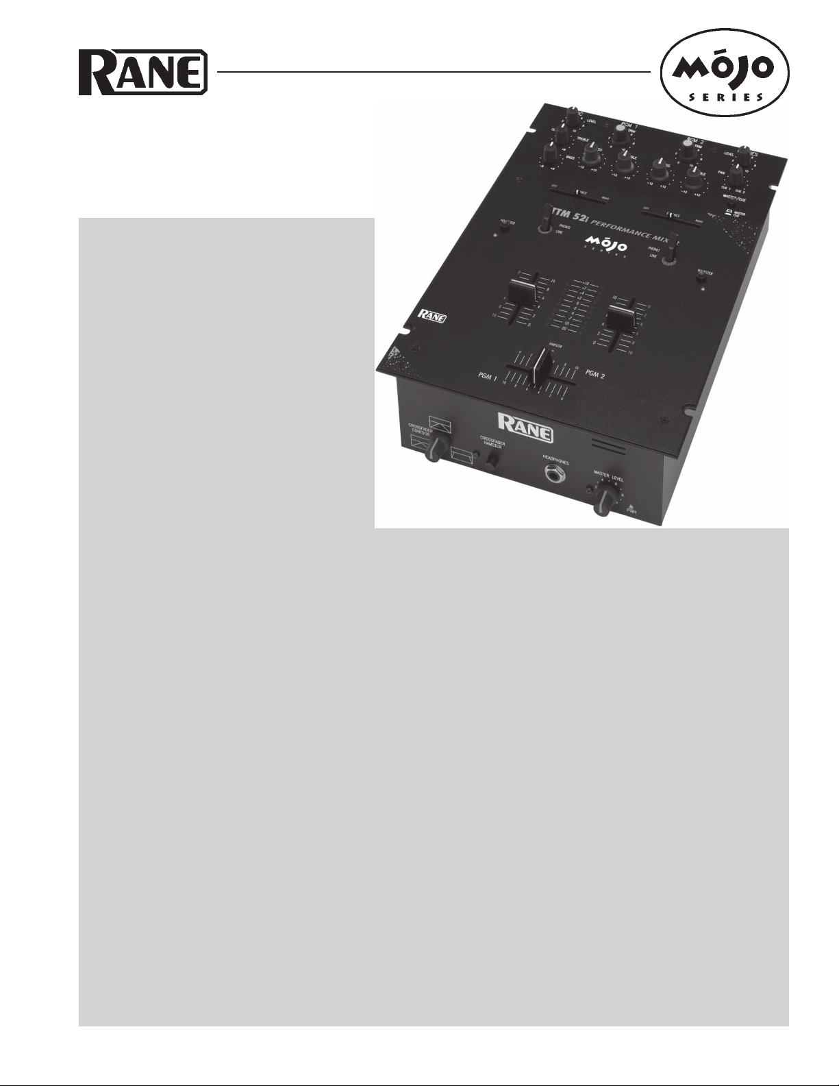
TTM 52i
MOJO PERFORMANCE MIXER
• GAIN TRIM: These controls are intended to
set the signal level before the Crossfader. Always set the GAIN TRIM controls to indicate an average signal level of +4
on the meter with the Program Faders set to maximum. Never use the GAIN TRIM controls to set the output level.
Always use the MASTER LEVEL control to set the output level. This is a very simple thing, yet makes a huge difference
in the performance of your mixer.
• PHONES: The headphone output of the TTM 52i is a high power output stage (unlike most you have used before). There
are some notable differences…
• The headphone output of the TTM 52i delivers very high volume into your headphones.
• To avoid pain, never put headphones on your head and then plug them in.
• Always start with the PHONES LEVEL turned down and then turn it up to the desired level.
• Because of the high current and low output impedance, never short one side to ground or short left and right
together as is possible with mono cup headphones. Note: Low power headphone stages typically use large
resistors on their outputs, which allow shorting, but prevent high power. The TTM 52i gives you high power
but does not allow shorting.
• MIC LEVEL: For best performance, keep this control at 0 when not in use.
• For instructions on rotating Phono/Line switches to the desired location, see page Manual-6.
• Do not spray cleaner or lubricant into the front of the Program Faders or Crossfader. The fluid will just run out the
bottom of the unit. Never use unapproved cleaner or lubricants such as skateboard wheel lube, as corrosive damage may
result, voiding the warranty. See page Manual-6 for cleaning and replacement instructions and cleaner recommendations.
• Never connect anything except an RS 1 Rane AC power supply to the thing that looks like a telephone jack on the rear.
This is an 18 VAC center-tapped power unit. Consult the Rane factory for replacement or substitution.
• WEAR PARTS: This product contains the following wear parts subject to the ninety (90) day warranty period described
on page Warranty-1: FT 45 Active Crossfader & Channel Fader Assembly(3); ST 2 Phono/Line Switch Assembly (2).
Manual-1
Page 2
AMPL(dBu)
AUDIO PRECI SION AMP-FREQ vs 04 NOV 98 0 8:11:55
20.000
18.000
16.000
14.000
12.000
10.000
8.0000
6.0000
4.0000
2.0000
0.0
-2.000
-4.000
-6.000
-8.000
-10.00
-12.00
-14.00
-16.00
-18.00
-20.00
20 100 1k 10k 20k
FREQ(Hz)
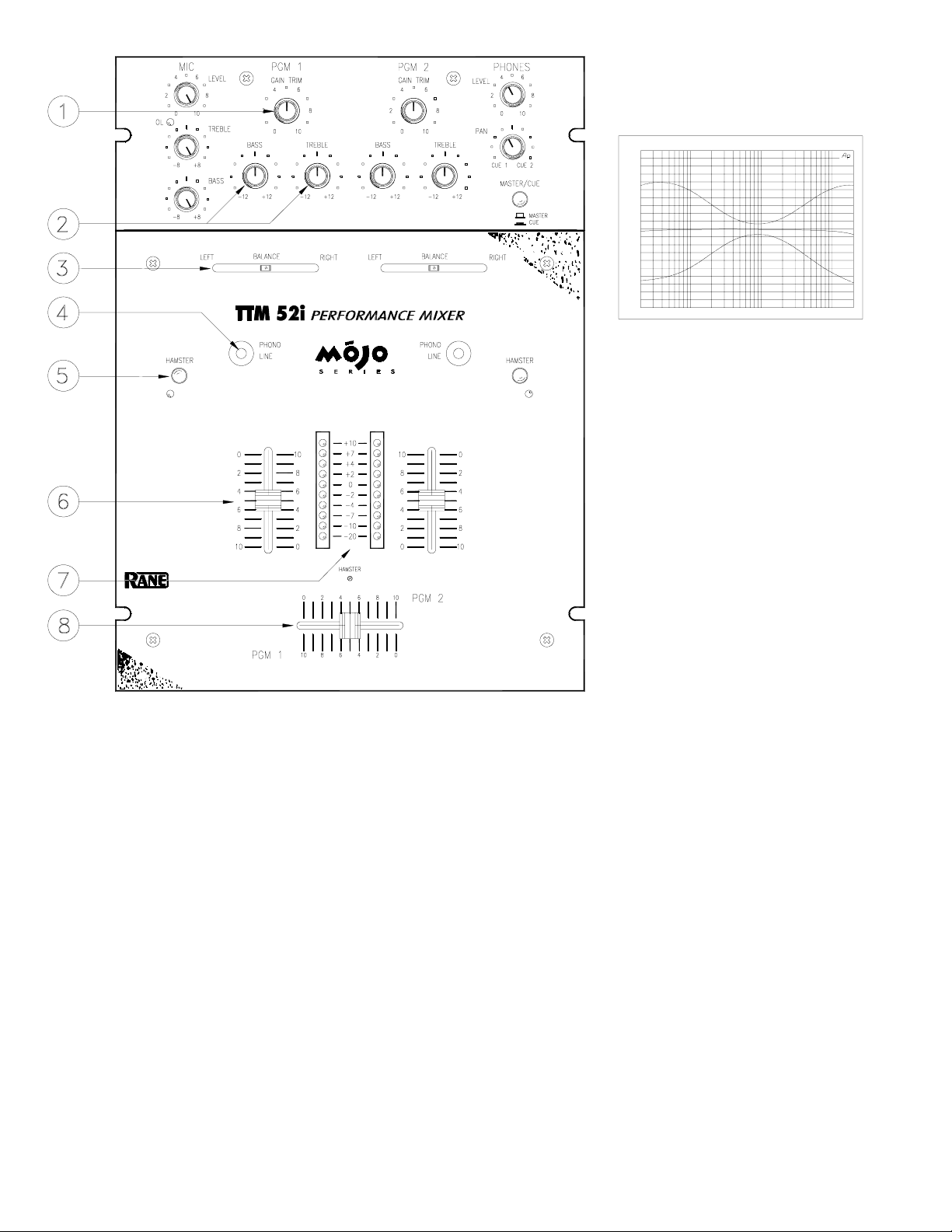
Figure 1. Bass & Treble Controls
PGM 1 and PGM 2 input GAIN TRIM controls are used to adjust input level. With the Program Faders (see ) at
maximum, set controls to give a peak reading of +4 on the meter. Set the Master Level to minimum while adjusting). It is
always best to run the input level at +4 to +7. Use the MASTER LEVEL (see ) control to adjust the volume at the
MASTER OUT (see ).
BASS and TREBLE controls provide ±12 dB of EQ for PGM 1 and PGM 2 . The graph shown in
Figure 1 indicates the response of the filters.
BALANCE controls are used for LEFT/RIGHT balance of PGM 1 and PGM 2 or for LEFT/RIGHT Pan effect. Push the
control to the left and sound moves to the left channel. Push the control to the right and sound moves to the right channel.
PHONO / LINE source select switches are provided for PGM 1 and PGM 2 . These are “clickless” switches suitable for
“transform scratch” applications. The switches are field replaceable and may be rotated in 45° increments. See Figure 4 on
page Manual-6 for rotation and replacement instructions.
HAMSTER switches are provided for PGM 1 and PGM 2 Program Faders. These switches reverse the operation of the
adjacent Program Fader . When engaged, signal is off with the Program Fader up, and maximum with the Program Fader
down.
Program Fader controls for PGM 1 and PGM 2 are ultra low noise, long-life, monorail devices. An ActiveFader™ design
completely isolates the control element from the audio, providing the highest reliability and performance. See page
Manual-6 for cleaning and replacement instructions.
Manual-2
Page 3
PGM 1 and PGM 2 Meters provide true L+R Dual Mono
indication of Post-Program Fader signal levels. Ten segment
resolution is provided with a one second peak hold indication.
With the Program Fader set to maximum, the input GAIN
TRIM should be set to indicate an average level of about +4.
Crossfader control is implemented using Ranes’ proprietary
ActiveFader™ design. As with the Program Faders, all audio
is isolated from the control element, greatly extending the life
and performance of the control. See page Manual-6 for cleaning
and replacement instructions
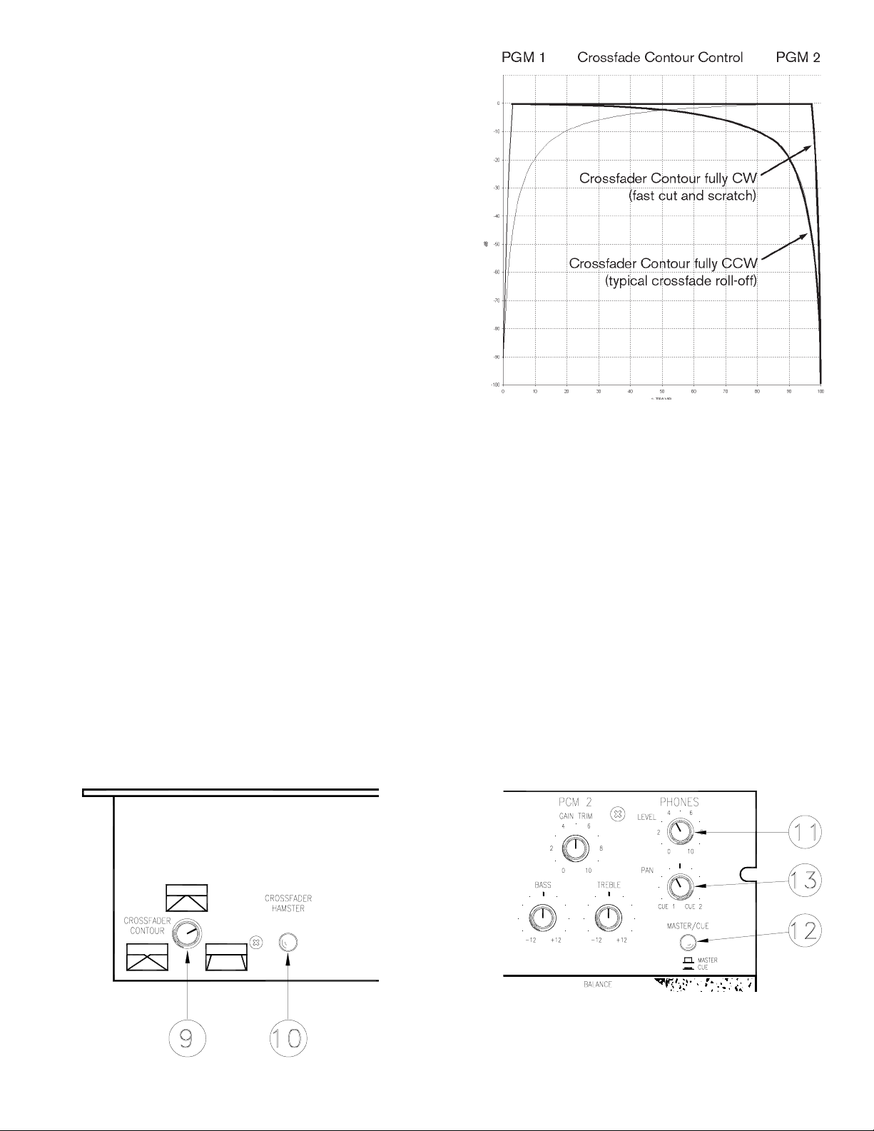
CROSSFADER CONTOUR control allows adjusting the
“shape” of the Crossfader response from a gentle curve for
smooth, long running fades, to the steep pitch required for top
performance cut and scratch effects shown in Figure 3.
CROSSFADER HAMSTER control allows reversing the
operation of the Crossfader. With the combination of
ActiveFader™, CONTOUR control, and HAMSTER control,
the TTM 52i provides a level of flexibility and performance
previously unavailable.
PHONES LEVEL control adjusts the loudness of the Headphone output signal. Always start with the LEVEL at minimum
(CCW) and increase to a comfortable level with signal present and your headphones on. This prevents tossing them across
the room after you put them on and plug in with the level set too high. The TTM 52i Headphone Amplifier delivers very
high sound pressure levels (SPL) into most headphone loads. Because of the high current and low output impedance, never
short one side to ground or short left and right together as is possible with mono cup headphones. Note: Low power head-
phone stages typically use large resistors on their outputs, which allow shorting, but prevent high power. The TTM 52i
gives you high power but does not allow shorting.
Figure 3. Crossfader Contour control
MASTER / CUE switch is used to select the HEADPHONES monitor source:
• Use MASTER to rehearse your performance. This signal is the same as that at the MASTER OUT, but is not
affected by the MASTER LEVEL control.
• Use CUE to monitor the Program Input signal, so you can “Cue” a signal before fading in. This signal is not
affected by the Program Faders or Crossfader.
PHONES PAN control is only active when CUE is selected. This control allows you to PAN between Program 1 or
Program 2.
Manual-3
Page 4

HEADPHONES jack provides a high current output, capable of
driving headphones between 8 ohms and 600 ohms. Because the
amplifier is capable of high current drive, it is important that the
outputs are not shorted together or to ground. Do NOT use single cup
phones that short tip and ring.
MASTER LEVEL adjusts the MASTER OUTPUT level for both the
balanced and unbalanced outputs.
POWER connector. This is not a telephone jack! Connect only the
Rane RS 1 power supply included with your TTM 52i. The ground
screw terminal may be used to solve potential grounding problems with
other equipment. See Chassis Grounding on page Manual-6.
MASTER OUT includes two sets of stereo outputs:
• The ¼" TRS jacks provide high current BALanced output, which
should be used whenever driving equipment with a balanced input or
running distances greater than about 10 feet. Due to the high drive capability and low impedance, never use a mono ¼" Tip/
Sleeve (no ring) cable in this jack; this grounds one side of the BALanced output.
• Use the UNBALanced output for shorter runs, such as connecting to a recorder, looping to another mixer, or to other local
signal processing or amplifiers. See Sound System Interconnection on page Manual-7.
PGM 1 and PGM 2 inputs include both PHONO and LINE input.
• PHONO 1 and PHONO 2 inputs are RIAA compensated inputs with 18 dB per octave, 20 Hz rumble filters.
• LINE 1 and LINE 2 inputs are unbalanced line level inputs with a nominal sensitivity of -10 dBV.
• PHONO/LINE selection is made as described in section .
• PGM 1 inputs are sent to the left side of the Crossfader. (HAMSTER switch out)
• PGM 2 inputs are sent to the right side of the Crossfader. (HAMSTER switch out)
PHONO GND terminals provide an independent ground connect point for two turntables. It is very important that each
turntable have a very good ground connection to one of these terminals. The thumb screws are not captivated, so use care
not to spin them off and lose them.
The MIC INPUT is a balanced ¼" TRS input specifically designed for a dynamic microphone.
MIC EFFECTS jacks are unbalanced mono ¼" Tip/Sleeve. This is an independent Effects Loop for the mic. There is no
engage switch, so the mic signal is always processed when you have an effects box connected.
• The SEND jack provides the output to your effects processor.
• The RETURN jack provides an input for the signal returning from your effects processor.
Manual-4
Page 5

MIC LEVEL sets the gain of the Mic Input. The range of
operation is off to +60 dB. There is no engage switch, so
set the MIC LEVEL to 0 when not in use.
The OL indicator lights 6 dB before clipping. Adjust the
MIC LEVEL so that the OL indicator flashes only when
you shout into the microphone.
MIC TREBLE and BASS controls provide as much as
8 dB of boost or 8 dB of cut. Response is flat when the
controls are set to center detent.
IMPORTANT NOTE
CHASSIS GROUNDING
If your system exhibits excessive hum or buzzing, there is an incompatibility in the grounding configuration between units
somewhere. Here are some things to try:
1. Check that the turntable grounding wires are connected to the PHONO GND posts (see ).
2. Try combinations of lifting grounds on units that are supplied with ground lift switches or links.
3. If your equipment is in a rack, verify that all chassis are tied to a good earth ground, either through the line cord grounding
pin or the rack screws to another grounded chassis, or tied to the ground screw located just above the POWER jack.
4. This unit’s outboard power supply does not ground the chassis through the line cord. Make sure that this unit is grounded
either to another chassis which is earth grounded, or directly to the grounding screw on an AC outlet cover by means of a
wire connected to a screw on the chassis with a star washer to guarantee proper contact (see ).
Please refer to Sound System Interconnection on page Manual-7 for further information on system grounding.
Manual-5
Page 6

Fader Cleaning
With heavy use in harsh environments, the
faders may need lubrication. This treatment
extends longevity and can make used faders as
good as new. The fader assembly must be
removed from the TTM 52i for proper cleaning. We recommend any of the following
cleaning solutions:
CAIG CaiLube MCL 100% spray lubricant
CAIG CaiLube MCL 5% spray cleaner
CRC 2-26 (www.crcindustries.com)
Figure 4. Phono/Line switch rotation or replacement
Rotating or Replacing Phono/Line
Switches
1. Remove the metal faceplace with a #2 philips screwdriver.
2. Remove the M2.5 x 6 mm screws with a #1 philips screwdriver.
3. If replacing, remove the jumper cable from the old switch and attach it to
the new switch.
4. Rotate or install switch to desired PHONO position.
5. Reinstall the M2.5 x 6 mm screws with a #1 philips screwdriver.
6. Replace the faceplate.
Replacement Wear Parts
Replacement Phono/Line switch assembly: ST 2
Replacement Fader Assembly: FT 45
All three faders use the same part.
Follow steps A and C in the Fader Cleaning instructions to the right.
Replacement assemblies available from your local Rane dealer.
Order CaiLube MCL
CAIG Laboratories, Inc.
12200 Thatcher Ct.
Poway, CA 92064
Phone 858-486-8388
Fax 858-486-8398
(www.caig.com)
CLEANING INSTRUCTIONS
A. Front panel removal
1. Disconnect the power cord.
2. Remove (3) slide fader knobs.
3. Remove (4) #4-40 front panel screws.
Faders and switches are now accessible.
B. Fader assembly removal
To remove any single fader:
1. Remove (2) 3mm screws.
2. Draw fader assembly out through hole.
3. Remove ribbon cable.
C. Fader cleaning
1. Hold the fader assembly away from the
mixer.
2. Position the fader at mid-travel.
3. Spray cleaner/lubricant into both ends of the
fader.
4. Move the fader over its full travel back and
forth a few times.
5. Shake excess fluid from the fader assembly.
6. Wipe off excess fluid.
D. Fader assembly installation
1. Connect the ribbon cable to the fader
assembly.
2. Place the fader assembly in position with the
ribbon connector to the right side or top, as
shown.
3. Line up the fader screw holes with the mixer
mounting holes.
4. Install (2 provided) 3mm screws. Using the
wrong screw will ruin the fader!
5. Replace the front panel and knobs.
®
from:
Manual-6
Page 7

SOUND SYSTEM INTERCONNECTION
Rane’s policy is to accommodate rather than dictate.
However, this document contains suggestions for external
wiring changes that should ideally only be implemented by
trained technical personnel. Safety regulations require that all
original grounding means provided from the factory be left
intact for safe operation. No guarantee of responsibility for
incidental or consequential damages can be provided. (In
other words, don’t modify cables, or try your own version of
grounding unless you really understand exactly what type of
output and input you have to connect.)
THE ABSOLUTE BEST RIGHT WAY TO DO IT
Use balanced lines and tie the cable shield to the metal
chassis (right where it enters the chassis) at both ends of the
cable.
A balanced line requires three separate conductors, two of
which are signal (+ and –) and one shield. The shield serves
to guard the sensitive audio lines from interference. Only by
using balanced line interconnects can you guarantee (yes,
guarantee) hum-free results. Always use twisted pair cable.
Chassis tying the shield at each end also guarantees the best
possible protection from RFI [radio frequency interference]
and other noises [neon signs, lighting dimmers].
THE NEXT BEST RIGHT WAY TO DO IT
The quickest, quietest and most foolproof method to
connect balanced and unbalanced is to transformer isolate
all unbalanced connections. Your audio dealer can recommend such a transformer.
The goal of transformer adaptors is to allow the use of
standard cables. With these transformer isolation boxes,
modification of cable assemblies is unnecessary. Virtually
any two pieces of audio equipment can be successfully
interfaced without risk of unwanted hum and noise.
Another way to create the necessary isolation is to use a
direct box. Originally named for its use to convert the high
impedance, high level output of an electric guitar to the low
impedance, low level input of a recording console, it allowed
the player to plug “directly” into the console. Now this term is
commonly used to describe any box used to convert unbalanced lines to balanced lines.
THE LAST BEST RIGHT WAY TO DO IT
If transformer isolation is not an option, special cable
assemblies are a last resort. The key here is to prevent the
shield currents from flowing into a unit whose grounding
scheme creates ground loops (hum) in the audio path (i.e.,
most audio equipment). Do not be tempted to use 3-prong to
2-prong “cheater” adapters to lift grounds. This is a dangerous
and illegal practice.
It is true that connecting both ends of the shield is theoretically the best way to interconnect equipment – though this
assumes the interconnected equipment is internally grounded
properly. Since most equipment is not internally grounded
properly, connecting both ends of the shield is not often
practiced, since doing so can create noisy interconnections.
involves disconnecting one end of the shield, even though one
can not buy off-the-shelf cables with the shield disconnected
at one end. The best end to disconnect is a matter of personal
preference and should be religiously obeyed; choose inputs or
outputs and always lift the side you choose (our drawings
happen to disconnect the outputs). If one end of the shield is
disconnected, the noisy hum current stops flowing and away
goes the hum — but only at low frequencies. A one-end-only
shield connection increases the possibility of high frequency
(radio) interference since the shield may act as an antenna.
Many reduce this potential RF interference by providing an
RF path through a small capacitor (0.1 or 0.01 microfarad
ceramic disc) connected from the lifted end of the shield to
the chassis. The fact that many modern day installers still
follow this one-end-only rule with consistent success indicates this and other acceptable solutions to RF issues exist,
though the increasing use of digital and wireless technology
greatly increases the possibility of future RF problems.
your particular interconnection needs. Find the appropriate
output configuration from either your mixer output or the MX
22 output (down the left side), and then match this with the
correct balanced or unbalanced input to the MX 22 or the
amplifer (down the right side.) An “off-the-shelf” cable may
be available or modifiable. Soldering should only be attempted by those trained in the art.
SUMMARY
balanced wiring with shields tied to the chassis at the point of
entry, or transformer isolate all unbalanced signals from
balanced signals) then there is no guarantee that a hum free
interconnect can be achieved, nor is there a definite scheme
that will assure noise free operation in all configurations.
WINNING THE WIRING WARS
• Use balanced connections whenever possible.
• Transformer isolate all unbalanced connections from
• Use special cable assemblies when unbalanced lines cannot
• Any unbalanced cable must be kept under ten feet (three
“Sound System Interconnection”. If you would like the
complete note, call or email the factory, download it from
Rane's web site http://www.rane.com, or ask your dealer for a
copy.
A common solution to these noisy hum and buzz problems
See the following page for suggested cable assemblies for
If you are unable to do things correctly (i.e. use fully
balanced connections.
be transformer isolated.
meters) in length. Lengths longer than this will amplify
the nasty side effects of unbalanced circuitry's ground
loops.
This information was condensed from Rane Note 110,
Manual-7
Page 8

VARIOUS XLR, RCA & ¼" CABLE ASSEMBLIES
©Rane Corporation 10802 47th Ave. W., Mukilteo WA 98275-5098 TEL (425)355-6000 FAX (425)347-7757 WEB http://www.rane.com
Manual-8
104033
Page 9

RISK OF ELECTRIC SHOCK
DO NOT OPEN
CAUTION
IMPORTANT SAFETY INSTRUCTIONS
1. Read these instructions.
2. Keep these instructions.
3. Heed all warnings.
4. Follow all instructions.
5. Do not use this apparatus near water.
6. Clean only with a dry cloth.
7. Do not block any ventilation openings. Install in accordance with manufacturer’s instructions.
8. Do not install near any heat sources such as radiators, registers, stoves, or other apparatus (including ampliers) that produce heat.
9. Do not defeat the safety purpose of the polarized or grounding-type plug. A polarized plug has two blades with one wider than the other. A grounding-type plug has two blades and a third grounding prong. e wide blade or third prong is provided for your safety. If the provided plug does not
t into your outlet, consult an electrician for replacement of the obsolete outlet.
10. Protect the power cord and plug from being walked on or pinched particularly at plugs, convenience receptacles, and the point where it exits from
the apparatus.
11. Only use attachments and accessories specied by Rane.
12. Use only with the cart, stand, tripod, bracket, or table specied by the manufacturer, or sold with the apparatus. When a cart is used, use caution
when moving the cart/apparatus combination to avoid injury from tip-over.
13. Unplug this apparatus during lightning storms or when unused for long periods of time.
14. Refer all servicing to qualied service personnel. Servicing is required when the apparatus has been damaged in any way, such as power supply
cord or plug is damaged, liquid has been spilled or objects have fallen into the apparatus, the apparatus has been exposed to rain or moisture, does
not operate normally, or has been dropped.
15. e plug on the power cord is the AC mains disconnect device and must remain readily operable. To completely disconnect this apparatus from
the AC mains, disconnect the power supply cord plug from the AC receptacle.
16. is apparatus shall be connected to a mains socket outlet with a protective earthing connection.
17. When permanently connected, an all-pole mains switch with a contact separation of at least 3 mm in each pole shall be incorporated in the electrical installation of the building.
18. If rackmounting, provide adequate ventilation. Equipment may be located above or below this apparatus, but some equipment (like large power
ampliers) may cause an unacceptable amount of hum or may generate too much heat and degrade the performance of this apparatus.
19. is apparatus may be installed in an industry standard equipment rack. Use screws through all mounting holes to provide the best support.
WARNING: To reduce the risk of re or electric shock, do not expose this apparatus to rain or moisture. Apparatus shall not be exposed to dripping
or splashing and no objects lled with liquids, such as vases, shall be placed on the apparatus.
NOTE: is equipment has been tested and found to comply with the limits for a Class B digital device, pursuant to part 15 of the FCC Rules. ese
limits are designed to provide reasonable protection against harmful interference in a residential installation. is equipment generates, uses and can
radiate radio frequency energy and, if not installed and used in accordance with the instructions, may cause harmful interference to radio communications. However, there is no guarantee that interference will not occur in a particular installation. If this equipment does cause harmful interference to
radio or television reception, which can be determined by turning the equipment o and on, the user is encouraged to try to correct the interference
by one or more of the following measures:
• Reorient or relocate the receiving antenna.
• Increase the separation between the equipment and receiver.
• Connect the equipment into an outlet on a circuit dierent from that to which the receiver is connected.
• Consult the dealer or an experienced radio/TV technician for help.
CAU TION: Changes or modications not expressly approved by Rane Corporation could void the user's authority to operate the equipment.
is Class B digital apparatus complies with Canadian ICES-003.
Cet appareil numérique de la classe B est conforme à la norme NMB-003 du Canada.
WARNING
To reduce the risk of electrical shock, do not open the unit. No user
serviceable parts inside. Refer servicing to qualied service personnel.
e symbols shown below are internationally accepted symbols that warn
of potential hazards with electrical products.
is symbol indicates that a dangerous voltage
constituting a risk of electric shock is present within
this unit.
is symbol indicates that there are important
operating and maintenance instructions in the
literature accompanying this unit.
 Loading...