

Page 1
OPERATORS MANUAL
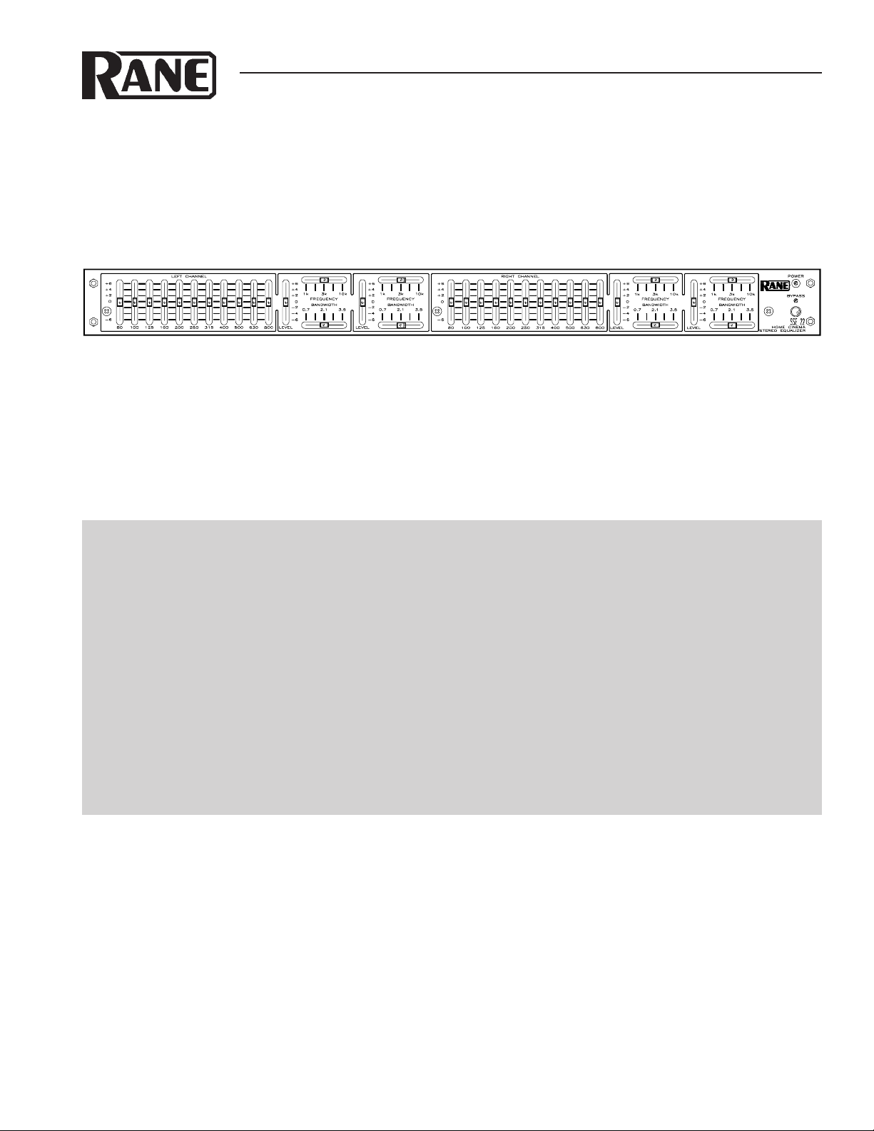
SSE 22
HOME CINEMA EQUALIZER
QUICK START
Great video is easy; great audio is hard, but a SSE 22 makes it a lot easier. Read at least this boxed section and you’ll be
on your way toward great audio.
Hook-up is intuitive: In from the controller, out to the amplifiers. Just follow the silkscreened legends near the gold-
plated RCA jacks on the rear of the unit.
Familiarity with other graphic and parametric equalizers makes the SSE 22 just as familiar. If this is your first equalizer,
be gentle; it can overwhelm you.
Use the BYPASS switch as an aid in comparing equalized results with unequalized results. Pushbutton in and locked
(LED on) is the bypassed (unequalized) mode; pushbutton out (LED off) is the normal equalized mode. See the Operating
Instructions on the page Manual-4 for alignment information.
Install the supplied security cover after completing all settings. Be sure the POWER light fits snugly into the hole in the
security cover.
Never connect anything except an approved Rane power supply to the thing that looks like a red telephone jack on
the rear of the unit. This is an AC input and requires special attention if you do not have a power supply exactly like the
one originally packed with your unit. See the full explanation of the power supply requirements on page Manual-3.
THX is a registered trademark of Lucasfilm Ltd.
Dolby and the double-D symbol are trademarks of Dolby Laboratories Licensing Corporation
Manual-1
Page 2
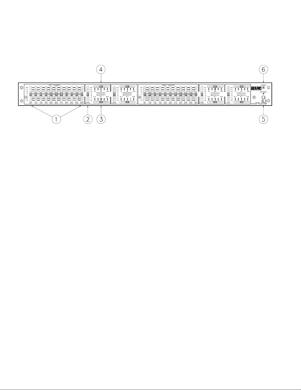
FRONT PANEL DESCRIPTION
1. Graphic equalizer filter level controls. The Left and Right Channels have eleven slide controls used to set the individual
levels of the constant-Q filters. Their range is ±6 dB. The grounded center-detent design ensures each filter is off when
positioned to 0 dB.
2. Parametric equalizer LEVEL control. Two parametric sections are included in each Channel with a ±6 dB range. This
control sets the amount of boost/cut for each parametric section. Same grounded center-detent design as the Graphic
Equalizer sections.
3. Parametric equalizer BANDWIDTH control. Slide control used to set the Bandwidth for this filter section. The range is
0.7-3.5 octaves.
4. Parametric equalizer FREQUENCY control. Slide control used to determine the center Frequency for this filter section.
The range is 1 kHz-10 kHz.
5. POWER indicator. This LED lights any time power is supplied from the Rane model RS 1 power supply (included). To
avoid confusion a distinction is made here between electrical and political.
6. Overall BYPASS switch & indicator. This pushbutton switch activates the “hard-wire” BYPASS function. When engaged
(red BYPASS LED on), the INPUT connectors directly tie to the OUTPUT connectors (hard-wired). Engaging this switch
converts the SSE 22 into a relatively expensive patch cord, albeit one with pretty lights. During the initial timed power-up
sequence or power loss of any sort, the SSE 22 is automatically in BYPASS mode.
Manual-2
Page 3

REAR PANEL DESCRIPTION
1. Remote POWER supply input. The unit is supplied from the factory with a Model RS 1 Remote Power Supply suitable for
connection to this input jack. The power requirements of the unit call for an 18 volt AC center-tapped transformer only. This
is not a telephone jack. Never use a power supply other than the one supplied, or a replacement approved by Rane Corporation. Using any other type of supply may damage the unit and void the warranty.
2. Chassis ground. A #6-32 screw is used for chassis grounding purposes. See the CHASSIS GROUNDING note below.
3. RCA OUTPUT connectors. Active unbalanced design. Use only high-grade RCA cables for interconnect to the power
amplifier inputs. For balanced amplifier inputs, use a Rane BB 44X Balance Buddy, or consult the RaneNote “Sound System
Interconnection” available from the factory or downloadable from the Rane web site.
4. RCA INPUT connectors. Active unbalanced design. Use only high-grade RCA cables for interconnect to the controller
outputs.
CHASSIS GROUNDING
If after hooking up your system it exhibits excessive hum or buzzing, there is an incompatibility in the grounding
configuration between units somewhere. Your mission, should you accept it, is to discover how your particular system
wants to be grounded. Here are some things to try:
1. Try combinations of lifting grounds on units that are supplied with ground lift switches or links.
2. If your equipment is in a rack, verify that all chassis are tied to a good earth ground, either through the line cord
grounding pin or the rack screws to another grounded chassis.
3. Units with outboard power supplies do NOT ground the chassis through the line cord. Make sure that these units are
grounded either to another chassis which is earth grounded, or directly to the grounding screw on an AC outlet cover by
means of a wire connected to a screw on the chassis with a star washer to guarantee proper contact.
Manual-3
Page 4

SSE 22 CONNECTION
When first connecting the SSE 22 to other components,
leave the power supply for last. This gives you a chance to
correct mistakes before damaging fragile speakers, ears and
nerves. The SSE 22 locates between the preamplifier/
processor and the amplifier.
INPUTS AND OUTPUTS
Connections are actively unbalanced and fitted with RCA
phono pin jacks. Use good quality cables and keep lengths as
short as possible. Longer length require balanced lines, using
an adaptor such as a Rane BB 44X Balance Buddy.
SIGNAL LEVELS
The SSE 22 is designed for audio reference levels of
0 dBr (150 mV rms), and provides a minimum headroom of
34.5 dB above reference, making it virtually unclippable.
With all LEVEL controls located in their 0 dB detented
positions, the SSE 22 operates with unity gain from Input to
Output. No additional gain settings are necessary. Use the
SSE 22 only for specific equalization, not level control.
SSE 22 BLOCK DIAGRAM
Manual-4
Page 5

OPERATING INSTRUCTIONS
STEREO EQUALIZATION
Depending on your philosophy, equalizers can perform
the role of fancy tone controls or correct speaker power
response in a room. The room is an extention of the speaker
cabinet, for the same speaker can sound different in different
rooms. Even more critical are in-wall speakers, which depend
on the wall as an extension of the cabinet, but not all walls
have the same construction or size. These differences are
more noticeable and specific in the lower frequencies where
1/3-octave EQ is required. The high frequencies need less
control, as they are less susceptible to room acoustics.
The SSE 22 can be adjusted by ear, but we highly recommend the use of a 1/3-octave realtime analyzer or other
similar test equipment. The results will be more accurate with
less response variance from channel to channel.
SURROUND CHANNEL ALIGNMENT
Whether the home cinema system is Dolby Pro-Logic,
Home THX, or Dolby Digital, the same principle applies: to
flatten the power response of the surrounds in the room.
There are no special curves to follow. Even though the
controller may have a preset filter for a given listening mode,
set the surrounds for a flat power response, just like the front
channels. Since surrounds may be of a different design than
the front channels, equalization can help the front and rear
speakers sound more similar, important when the sound pans
from front to back (as the spaceship flies overhead).
Test equipment is required to properly align a multichannel system, such as a 1/3-octave realtime analyzer,
preferable a model with a memory averaging function. Follow
the instructions with the analyzer. Though more time consuming, a test CD and a sound pressure level meter can work. For
this method, see the RaneNote on Home Theater Systems,
available from the factory or downloadable from the Rane
web site.
Align the system for a flat average response from each
Channel. Begin with the center channel, then tune each
channel separately with the other channels turned off.
Direct-radiating and dipolar surround designs follow the
same guidelines. With test equipment, measure the room, not
the speaker. Place the mic near the primary listening
position(s), aiming straight up, not aimed at the speaker.
For those using the THX 44 for the front channels and the
SSE 22 for the rear, follow the alignment procedure specified
by Lucasfilm Ltd. as described in the “Home THX® Audio
System Room Equalization Manual”. It is not possible to
align a Home THX Audio system without the use of proper
procedures and a one-third octave realtime analyzer with
averaging. It cannot be done by ear. The special THX “Wow”
Laserdisc comes in handy as well (only supplied with some
THX controllers or a licensed THX installer). The same
procedure may be used for Dolby Pro-Logic and Digital
systems without the THX “Wow” Laserdisc.
SETTING CURVES USING AN ANALYZER
Our unique interpolating constant-Q circuitry makes
setting curves easy. For the graphic sections, what you see is
what you get – more so than on any other equalizer. Referring
to your room result curves, begin by positioning the sliders to
create the inverse curve shown by the instrumentation. Most
applications require only a few dB of boost or cut. If more is
required, use architectural and mechanical means: add,
remove, or relocate acoustically sensitive items (speakers,
drapes, carpets, mirrors, etc.) as required.
The analyzer comes with a pink noise source. Simply
connect the noise source to the right or left auxiliary input on
the preamp, adjust volume for a comfortable listening level,
and begin alignment.
Some creativity is required when using one of these
devices on surround channels, as there is no direct surround
channel input on the preamp. If you are using the THX
“Wow” Laserdisc, the solution is simple. Use the pink noise
Chapters 8-11 on Side 2 for all channels in the system, with
the controller in Dolby Pro-Logic mode. Create a loop with
the A-B Repeat function on the laserdisc player for each
chapter, and align each channel one at a time. Chapter 11 is
the surround channel noise source. Disconnect the right
surround when you align the left surround, and vice versa.
Some analyzers require their own noise source to be used.
A “Wow” Laserdisc may not be available. For these situations, some temporary patching is required. Connect the pink
noise to an auxiliary Left input on the processor. Temporarily
connect the preamps Left front output to the Left SSE 22
Input. Connect the SSE 22 Outputs to an amplifier and
surrounds. With the SSE 22 set flat (0 dB), adjust volume to a
comfortable level on the processor and leave it set. Perform
the left surround alignment. Now move the cable coming
from the processor to the Right SSE 22 Input, and align. Once
alignment is complete, remove the analyzer and connect the
cables to their normal routing.
Once equalization for all channels is set, perform a final
channel level check with the Dolby Test on the processor. Use
the enclosed security cover to guard your precious settings
from inquisitive guests.
USING THE BYPASS SWITCH
The SSE 22 provides an overall BYPASS switch &
indicator as a useful tool for optimizing settings. Use the
BYPASS switch for making quick “A-B” comparisons, i.e.,
comparing “A”, equalized (BYPASS out, LED off), versus
“B”, unequalized (BYPASS in, LED on).
Since the SSE 22 always operates at unity gain in the
BYPASS mode, comparison can result in startling level
differences between the two when a lot of boosting or cutting
has been done. Therefore, keep the system level down during
the first use of the BYPASS switch. Be careful!
Manual-5
Page 6

SSE 22 FEATURES AND SPECIFICATIONS
Parameter Specification Limit Units Conditions/Comments
Graphic Equalizer Sections: Left & Right
..........Bands (11) 1/3-Octave ISO Spacing From 80 Hz to 800 Hz
..........Type Interpolating Constant-Q Smooth Combining
..........Travel 20 mm Positive Grounded Center Detent
..........Range ±6 0.25 dB
Parametric Equalizer Sections: Left & Right
..........Frequency Range 1 kHz-10 kHz
..........Bandwidth Range 0.7-3.5 octaves (Q=2.0-0.33)
..........Amplitude Range ±6 0.25 dB
Inputs: Type Active Unbalanced RCA Phono Connectors
..........Impedance 10k 1% ohms
..........Maximum Level 34.5 1 dBr 11 Volts peak
Outputs: Type Active Unbalanced RCA Phono Connectors
..........Impedance 50 1% ohms
..........Maximum Level +34.5 > = 2k ohm 1 dBr 11 Volts peak
Frequency Response 20 Hz-20 kHz +0/-.2 dB
Group Delay Linear (Minimum Phase) ±5° 20-20 kHz
THD+Noise 0.001 .0005 % 1 kHz, +27.5 dBr (5 V peak)
Signal-to-Noise 120 1 dB re 5 V pk; A-wtg; input short; flat
-92.5 1 dBr A-wtg; input short, flat
-90.5 1 dBr 20 kHz BW; input short, flat
-84.5 1 dBr A-wtg; input short, full boost
-87.5 1 dBr A-wtg; input short, full cut
Dynamic Range 127 1 dB Max out/noise floor (+34.5dBr/-92.5dBr)
Channel Separation 90 min dB 20-20 kHz
Unit: Agency Listing
..........120 VAC model Class 2 Equipment National Electrical Code
UL 813 Exempt Class 2
CSA Exempt Class 2
..........230 VAC model VDE, SELV Safety Extra Low Voltage
CE-EMC EMC directive 89/336/EEC
CE-Safety Exempt Article 1 of LV Directive 73/23/EEC
Power Supply: Agency Listing Class 2 Equipment
..........120 VAC model UL listed File no. E88261
CSA Certified File no. LR58948
..........230 VAC model CE-EMC Meets EMC Directive 89/336/EEC
CE-Safety LV Directive 73/23/EEC
Power Supply: Input 18 VAC w/center tap 10% Vrms Model RS 1
..........Current 750 max mA RMS Current From Remote Supply
Unit: Size 1.75"H x 19"W x 8.5"D (2U) (4.4 cm x 48.3 cm x 21.6 cm)
17 3/8" wide w/o rack ears (44.2 cm wide without rack ears)
..........Weight 5 lb (2.3 kg)
Shipping: Size 4.25" x 20.3" x 13.75" (11 cm x 52 cm x 35 cm)
..........Weight 8 lb (3.6 kg)
Note: 0 dBr=150 mVrms=Home THX Equalizer Reference Level
©Rane Corporation 10802 47th Ave. W., Mukilteo WA 98275-5098 TEL (425)355-6000 FAX (425)347-7757 WEB http://www.rane.com
All features & specifications subject to change without notice. AUG97
Manual-6
 Loading...