

Page 1

OPERATORS MANUAL
16dB
4dB
SPLITTER
MIXE
R
ROUTER
SRM 66
1 432
MIX INPUT HEADROOM
65
EXE
DATA
PWR
SHIFT
VIEWING
N
ANGL
E
X
M
I
A
M
Quick Start
Before complaining about having to install the SRM 66 in
the rack twice (because you forgot to set the internal highpass
filters ahead of time), take note that the very first (non-joke)
line in this manual is: Before installing the SRM 66 in a rack,
be sure the internally switchable 80 Hertz highpass filters are set
as desired. ey are shipped with the filters in the OUT (disabled)
position. (See the bottom of page Manual-2 to enable these filters.)
If you were smart enough to read this much of the manual, this
paragraph may already have saved you a few minutes of your
life – you’re welcome. If you’ve learned the hard way, hopefully
you’ve learned an important lesson – read at least the first line in
the manual first.
Make all connections with the power and amplifiers off. e
SRM 66 is fully balanced and equipped with removable 5-position Euroblock connectors. Inputs and Outputs are arranged on
Euroblocks in pairs, i.e., 1&2, 3&4, 5&6.
Be sure the FP LOCK switch (on rear) is in the out position
to enable programming from the front panel.
Apply power so the PWR LED lights and LCD screen glows
with the SRM 66 welcome marquee. During initialization, the
startup muting circuit immediately starts counting down from
40 in the Limiter Gain Reduction area of the display. Adjust the
VIEWING ANGLE with a miniature screwdriver if necessary.
With signal applied to the Inputs, watch the MIX INPUT
HEADROOM indicators. ese verify correct setting of the
Output of the previous device and the rear panel Input GAIN
switches. Adjust so that 4 dB lights during peaks.
Navigating the LCD Edit pages is simple. e top buttons
marked << and >> are the left/right Page scroll buttons. ese
navigate to Output pages 1 through 6, the assign Outputs to
Output Group page, the assign Remote to Group page, the assign
Group to Master Remote page, the Group Levels page, and the
Memory page.
SRM 66
SPLITTER ROUTER MIXER
e bottom buttons marked
buttons. ese select the (underlined) parameter to edit.
Rotating the DATA knob changes the parameter setting.
Let’s start by navigating to Output 1’s page. Move the cursor
under IN1. With a signal driving Input 1 and a working ampli-
fier connected to Output 1, adjust the DATA knob to the desired
level. Adjust any other Input going to Output 1. MST controls
the Master level of Output 1. LIM sets the Limit reshold of
the Limiter circuit for Output 1.
To Copy settings from Output 1 to any other Output, move
the cursor to Copy. Press the EXE button. e display now
reads Paste. Change the page to the one you want these same
settings in, and press EXE again. e settings have now been
pasted into the new Output.
Settings may be Stored and Recalled in the Memory Page. To
Store, select the Store field, select a Memory number with the
DATA wheel and press EXE. To Recall, select the Recall field,
select a Memory number with the DATA wheel and press EXE.
Look deeper into this manual for information on remote control
of Memories, level adjustments and, the most powerful feature
of the SRM 66, Output Groups which “link” Output levels. A
Master Remote feature allows controlling the level of any Output
Groups assigned to it.
For best signal control and dynamic range, turn the Master
Output off when no Inputs are routed to a given output.
CAUTION: Never connect anything except an approved
Rane power supply to the thing that looks like a red telephone
jack on the rear of the SRM 66. is is an 18 VAC center
tapped power input. Consult the Rane factory for a replacement
or substitute.
< and > are the left/right cursor
WEAR PARTS: is product contains no wear parts.
Manual-1
Page 2
Front Panel Description
16dB
4dB
SPLITTER
MIXE
R
ROUTER
SRM 66
1 432
MIX INPUT HEADROOM
65
EXE
DATA
PWR
SHIFT
VIEWING
N
ANGL
E
X
M
I
A
M
1 2 4
3 6
85
7
MIX INPUT HEADROOM meters. ese assist setting of the rear panel GAIN switches as well as the output level of the pre-
ceding device. e 16 dB and 4 dB LEDs indicate the remaining headroom for each of the six Inputs. Optimal settings allow the 4
dB LEDs to flash only during signal peaks.
Edit Pages. is 2x40 backlit LCD screen displays the Edit pages for controlling and revealing all the functions of the SRM 66
(see ). Refer to the OPERATION section on page Manual-4 for details.
VIEWING ANGLE adjust. is recessed adjustment allows optimizing the LCD display contrast for various vertical viewing
angles.
DATA wheel. Allows adjustment of a field parameter after it is selected with the Page (see ) and Cursor (see ) buttons. Turn-
ing the DATA wheel clockwise increases the parameter, and turning it counterclockwise decreases the parameter.
Page buttons. e Previous Page << and Next Page >> buttons scroll through all 10 Edit pages. When the EXE button is held
and MAX >> is pressed, the selected parameter jumps to its highest value (see ).
Cursor buttons. e Previous < and Next > cursor buttons scroll through each of the adjustable fields on each page. ese but-
tons select each adjustable parameter along the bottom row by moving the underline left < or right >. When any parameter is
selected, the DATA wheel adjusts that parameter. When the EXE button is held and MIN > is pressed, the selected parameter
jumps to its lowest value (see ).
EXE (Execute) button. Several commands are implemented with this button. Holding down EXE while pressing MAX >> alters
the selected parameter to its highest nominal value. Holding down EXE while pressing MIN > alters the selected parameter to its
lowest value or Off. Pressing EXE when the Copy, Paste, Recall, Store, and Zero commands are selected executes that func-
tion.
Power indicator. In case the backlit Edit display isn’t enough assurance, this yellow indicator glows anytime adequate power is
applied to the SRM 66, alerting you to its on condition.
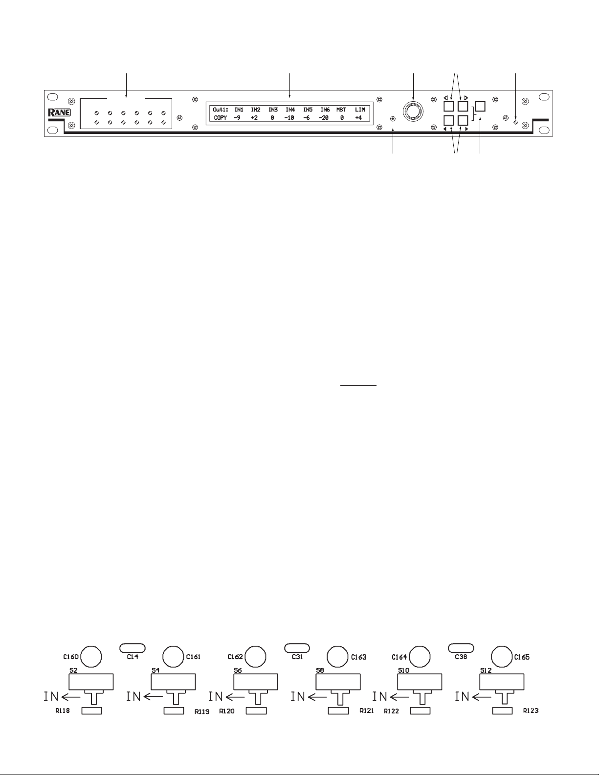
Internal 80 Hz High Pass Filters
Each Output of the SRM 66 features an internally switchable 80 Hz highpass filter. ese filters roll off low frequencies. is
is useful in small sound reinforcement systems or for use with constant voltage line transformers. ese switches are shipped
from the factory in the OUT position. If you wish to enable any or all of the filters for each Output, it will be necessary to
remove the unit’s top cover before installation. Locate the switches near the center of the board, as shown below. S2 = Output 1,
S4 = Output 2, S6 = Output 3, S8 = Output 4, S10 = Output 5, and S12 = Output 6.
Manual-2
Page 3

Rear Panel Description
-10dBV
+4dBu
GAIN GAIN GAIN GAIN GAIN GAIN
PORT (RIP)
REMOTE INTERF
ACE
MADE IN U.S.A.
MEMORY RECALL
PORT (MRP)
N108
RANE CORP.
-
+
+4dBu
-10dBV
-
+
-
+
-
+
7 8 A B +V -V
-
+
-
+
-
+
-
+
-
+
-
+
-
+
-
+
-
+
-
+
-
+
-
+
-
+
-
+
-
+
-
+
-
+
-
+
-
+
-
+
LOCK
COM 1 2 3 4 5 6
CLASS 2 EQUIPMENT
COMPLIES WITH PART 15 OF THE FCC RULES FOR A CLASS 'B' COMPUTING DEVICE
GAIN GAIN GAIN GAIN GAIN GAIN
COM 1 2 3 4 5 6 7 8
FP
-VA B +V
SRM 66
12
INPUTS
4 352 1 6
OUTPUTS
4 356
750mA
POWER
2
1
4
5
6
7
8
9
3
POWER input connector. Use only an RS 1, or other Remote AC power supply approved by Rane. is unit is supplied with a
remote power supply suitable for connection to this input jack. Consult the factory for a replacement or a substitute. is unit’s
power input is designed for an AC supply, delivering 18 volts, from a center-tapped transformer capable of supplying at least the
750 mA of current demanded by this product. Using any other type of supply may damage the unit and void the warranty.
Chassis ground point. A #6-32 screw is supplied for chassis grounding purposes. Units with external power supplies such as this
SRM 66 supply do not ground the chassis to earth through the line cord. is chassis connection is critical and in most installations, required by law. Many chassis ground this point to an amplifier chassis ground or directly to the grounding screw on a
grounded AC outlet cover by means of a wire secured on both ends with star washers to guarantee proper contact. See the Chassis
Grounding note on the next page.
FP LOCK button. When pressed in, locks out all front panel control except for Group Levels and Memory Recall. e
SR 1L remotes (sold separately) are also able to control Group Levels with FP LOCK engaged. e user is able to view, but not
edit, all Edit pages.
MEMORY RECALL PORT (MRP). is Port allows any remote switch to recall any of the system Memories. e first eight
Memories recall with simple switch closure to a single pin. A “binary” wiring mode allows access to more complex Memory recall
functions. See Figure 8 on page Manual-8. Complete programmability of the MRP is possible using the Edit MRP Configuration
feature found in SRM Exchange software. See DSC 1 & SRM Exchange software on page Manual-9.
REMOTE INTERFACE PORT (RIP). is Port supports up to seven optional SR 1L “Smart” digital Remote controls (see page
Manual-6). Each Remote may be assigned to adjust the Level of any one of the six SRM 66 Output Groups or the Master Group.
OUTPUT GAIN switches. ese assist setting the optimal gain structure of the Output stage, depending on what the following
device would like to see (or hear). Balanced signals usually require a +4 dBu setting (button out), and unbalanced signals usually
require the -10 dBV setting (button in).
OUTPUTS. ese balanced Euroblock connectors may be wired balanced or unbalanced. See page Manual-1 or the RaneNote,
“Sound System Interconnection” later in this manual for assistance.
INPUT GAIN switches. ese assist setting the optimal gain structure of the Input stage, depending on the level from the previ-
ous device. Balanced signals usually require a +4 dBu setting (button out), and unbalanced signals usually require the -10 dBV
setting (button in). Use the MIX INPUT HEADROOM meters as a guide for determining GAIN switch position (see in the
Front Panel Description).
INPUTS. ese line-level balanced Euroblock connectors may be wired balanced or unbalanced. Microphones require a pream-
plifier (see the Rane MS 1B for a solution). See the next page and the RaneNote “Sound System Interconnection” elsewhere in this
manual for assistance with various wiring options.
Manual-3
Page 4

SRM 66 Connection
Balanced Operation
Connect the ‘+’ to ‘+’, ‘–’ to ‘–’, and shield to shield. Use only
when driving from a true balanced source and driving to a true
balanced destination — either transformer coupled or active
drive.
Unbalanced Operation
To avoid nasty side effects such as hum and noise – which are
consequences of unbalanced operation – keep cable lengths as
short as possible. For lengths longer than ten feet, use a transformer such as a Rane BB 44x.
Coming from an unbalanced source, the SRM 66’s Input
uses two conductors plus a shield; connect ‘+’ to ‘+’, the unbalanced source ground to ‘–’, and the cable shield to the SRM 66’s
ground.
Going to an unbalanced device using a single conductor plus
a shield, connect ‘+’ to ‘+’, leave ‘–’ unconnected and connect the
cable shields at both ends to ground.
Combination Operation
For combined balanced and unbalanced operation, use
whichever half of the above instructions apply for each end. See
the “Sound System Interconnection” RaneNote included with
this manual for more information on cabling and grounding
requirements.
FP Lock
e recessed FP LOCK switch (on the rear) locks out all
front panel control except for Group Levels and Memory Recall.
With FP LOCK engaged, the SR 1L Remotes are able to control
Group Levels, and all Edit Pages are viewable but not editable.
Chassis Grounding
If after hooking up your system it exhibits excessive hum or
buzzing, there is an incompatibility in the grounding inside a
unit(s) or between units somewhere. Your mission is to discover
how your particular system wants to be grounded. Try these
things:
1. Try combinations of lifting grounds on units that are supplied
with ground lift switches or links. Other than in your own
home, it is illegal and unsafe to use 2-prong to 3-prong AC
line cord cheaters, even though this is a common (short term)
remedy. Using such “cheaters” can (and has been known to)
electrocute or kill people. [Ace Frehley and Keith Richards
survived; Keith Relf (e Yardbirds) and John Rostill (e
Shadows) did not.]
2. If your equipment is in a rack, verify that all chassis are tied to
a good earth ground, either through the AC line cord ground
ing pin (3
rd
prong) or the rack screws to another grounded
chassis.
3. Units with outboard power supplies may not ground the chas-
sis through the line cord. Make sure these units are grounded
either to another chassis which is earth grounded, or directly
to the grounding screw on a grounded AC outlet cover.
Please refer to the RaneNote “Sound System Interconnection”
(elsewhere in this manual) for further information.
-
Manual-4
Page 5

Output
Page,
where [x]
indicates
the Output
currently
being
edited.
Limiter gain reduction is
indicated in [y]dB when
the Limiter is ac
tive.
Out[x]:[y] IN1 IN2 IN3 IN4 IN5 IN6 MST LIM
Copy +6 -3 +6 Off +6 -25 +0 Max
Copy parameters of current page to clipboard.
Paste contents of clipboard to current page.
Recall[n] loads current page parameters from
Memory[n], where [n]=Memory 1-24.
Sets the
Limiter
Threshold
for Output
[x].
Operation
The User Interface
All SRM 66 programming is done with the Data wheel and
the front panel buttons using one of the eleven LCD pages. Each
page consists of the page name, multiple parameter fields and
possible Command fields and status indicators.
To navigate between pages use the Next Page (>>) and Previous Page (<<) buttons. Within a page the Next (>) and Previous
(<) buttons move the cursor to each field.
Above each parameter field is a label indicating its function.
Once the cursor is positioned beneath the desired parameter
field, turn the Data wheel clockwise to increase the value and
counter-clockwise to decrease it. To quickly jump to extreme
maximum or minimum values, hold down the Shift (EXE)
button and press either the MAX (>>) or MIN (>) buttons. For
added safety, executing MAX for the Input mix levels sets the
level to unity or zero gain, not +6 dB which is the actual maximum.
Command Fields
Most pages contain a Command field. Here you can Copy
settings from the current page to the clipboard, Paste settings
from the clipboard, Recall page settings from memory, and Zero
all page settings.
To access a command, position the cursor under the Com
mand field, use the Data wheel to select the desired command
(not all commands are available in all pages) and press the EXE
button.
Clipboard
ere are actually three separate clipboards in the SRM 66:
one for an Output’s settings (shared by all Outputs), one for the
Remote to Group settings, and one for the Output to Group set
tings. Using the clipboard can greatly simplify and speed setting
up multiple Outputs or multiple Memories. e clipboard settings
are lost whenever power is removed.
Status Indicators
Next to the page name in many pages is a Status Indicator.
In the Output pages it shows the current amount of Limiter gain
reduction or startup muting. If there is no gain reduction being
applied, the field is blank. On the Memory page an asterisk (*)
appears in this field whenever the current working Memory does
not match the last recalled Memory.
Programming the SRM 66
Programming each SRM 66 Output requires only one edit
page as in Figure 1. Note that unique Input mix levels are pos
sible for each Output. All adjustments are in 1 dB steps.
e following parameters define each Output:
IN1 Input one mix Level +6 dB to -25 dB, Off
IN2 Input two mix Level +6 dB to -25 dB, Off
IN3 Input three mix Level +6 dB to -25 dB, Off
IN4 Input four mix Level +6 dB to -25 dB, Off
IN5 Input five mix Level +6 dB to -25 dB, Off
IN6 Input six mix Level +6 dB to -25 dB, Off
MST Master mix Level +0 dB to -59 dB, Off
LIM Limit reshold Max (0 dB) to -28 dB re: clip point.
Figure 1. Output Edit Page
Output Groups
e SRM 66 uses Output Groups to link the attenuation
level and Limiter gain reduction of one or more Outputs. Any
one of the seven possible SR 1L remote controls can then be as-
-
signed to control an Output Group Level. e SRM 66 can also
assign any number of the six possible Output Groups to a Master
Group. Any number of the seven possible SR 1L Remotes can
then be assigned to control the Master Group Level. Understanding and utilizing the power of Groups is essential to harness
the power and versatility of the SRM 66.
e Output to Group Assign page is shown in Figure 2. Outputs can be assigned to 1 of 6 Output Groups or no Group (off ).
-
For example, a stereo Output pair would typically be assigned
to the same Output Group in order to ensure that the two stereo
Outputs limit together and are controlled by the same Output
Group Level. Output Group Levels may be controlled from the
Group Level page shown in Figure 3 or by any SR 1L remote
assigned to the Group on the Remote to Group page shown in
Figure 5.
e Group to Master Remote assignment page is shown in
Figure 4. Any number of the six (6) possible Output Groups
can be assigned to the Master Group. e Level of all Output
Groups assigned to the Master Group can be controlled by the
MST control on the Group Level page shown in Figure 3 or by
any SR 1L remote assigned to the Master Group on the Remote
to Group Assign page shown in Figure 5. is feature allows SR
1L remotes to independently control the level of up to six Zones
-
while allowing one or more Master Remotes to control the level
of all Zones.
Group Level parameters are independent of mix Input level
and Output Master level. Group Levels are not affected by Memory
changes. See the APPLICATIONS section for more discussion on
fully utilizing Group functionality.
Manual-5
Page 6

Group attenuation levels
page. This has the same
action as controlling from
optional SR 1 Remote(s).
Group Lvls G1 G2 G3 G4 G5 G6
Zero All -20 -10 0 Off 0 -6
Groups G1 through G6 may be attenuated
0 dB to -29 dB or set to Off.
When Zero All is selected, pressing EXE
sets all Group attenutation levels to 0 dB.
Output to Group Page,
where Outputs are
assigned to 1 of 6 Groups.
Out->Grp Out1 Out2 Out3 Out4 Out5 Out6
Copy G1 Off G6 G4 G3 G2
Channels Out1 through Out6 may be
assigned to 1 of 6 Groups or set to
Off.
Figure 2. Output to Group Edit Page
Remote to Group
Page, where Remotes
are assigned to 1 of 6
Groups.
Rmt->Grp R1 R2 R3 R4 R5 R6
Copy G1 Off G6 G4 G3 G2
Remotes R1 through R6 may be assigned
to 1 of 6 Groups or set to
Off.
Copy parameters of current page to clipboard.
Paste contents of clipboard to current page.
Recall[n] loads current page parameters from
Memory[n], where [n]=Memory number.
Group to Master Remote
page allows any group to
be assigned to the Master
Remote.
Grp-> Mstr Rmt G1 G2 G3 G4 G5 G6
Copy On Off Off Off On Off
Assigns Groups G1 through G6 to
Master Remote(s).
N
O
4321
N
O
4321
REMOTE
REMOTE
MASTER
SLAVE
SLAVE
Do not connect V+ between Master and Slave units.
SR 1L
SR 1L
SRM 66
SRM 66
SRM 66
+VBA -V
-V+VBA
REMOTE INTERFACE
PORT (RIP
)
-VA B +V
A B +V -V
REMOTE INTERFACE
PORT (RIP
)
-VA B +V
A B +V -V
REMOTE INTERFACE
PORT (RIP
)
ADDRESS
4
R
2
1
T
+VA B -V
ENCODER
LOCK
4
ADDRESS
2
1
R
-VA B +V
T
Remote Interface Port (RIP)
Modes
ere are three Remote Interface Port modes. e default
RIP mode allows communication to SR 1L Remotes.
When using the DSC 1 accessory, the RIP parameter must
be set to DSC. (See DSC 1 & SRM Exchange Software.)
When using the SRM 66’s Master Slave feature, RIP must be
set to SLAVE. A single SR 1L can control Output Groups across
multiple SRM 66’s. For information on Master/Slave functionality, see the RaneNote “Advanced Applications of the Ingenious
SRM 66 and SR 1L.”
SR 1L Remotes
e SRM 66 provides a Remote Interface Port which sup
ports up to seven optional SR 1L “Smart” Remote controls. e
SR 1L has 31 LEDs to indicate the Group’s current attenuation
setting of 0 to 29 dB in 1 dB steps, the last step is OFF. It is
designed to mount in a standard U.S. electrical box with a minimum depth of 2¼ inches, and can be covered with a standard
Decora® plate cover. (Decora is a registered trademark of Leviton). See the SR 1L Data Sheet for hookup and operation.
-
Figure 3. Group Levels Edit Page
Figure 4. Group to Master Remote Assign Page
Manual-6
Figure 5. Remote to Group Assign Page
Figure 6. Multiple SR 1L Remote and SRM 66 wiring
Page 7

Mem[n]* Store Recall
Memory [n] Stored! [ n] [ n]
*
RIP
[SR1]
Init
Fact
Memory location
to Recall. Select
Memory
with
DATA wheel and
press EXE to
Recall
.
Selects mode for the
Remote Interface Port.
Select SR1 when used
with SR 1 Remote
devices. DSC mode
allows future
communication options.
Memory location to
Store. Select Memory
with DATA wheel and
press EXE to Store.
After Execution, this
confirms that Memory
[n] has been Stored
or Recalled.
Selects mode for
standard Factory or
preset Room Combine
Programs
Memory page. The
indicates current
parameter settings do not
match the recalled
Memory; [n] indicates the
last recalled Memory.
87654321C
Mic
Switch
Memory
Switch
Paging
Mode
DSC 1
DIGITAL
SERIAL
CONVERTE
R
INPUT
RS 232 DATA
INTERFACE
REMOT
E
PORT (RIP)
RANE CORP.
MADE IN U.S.A.
DSC 1 & SRM Exchange
e optional Rane DSC 1 accessory provides a bridge to
connect a PC’s RS-232 port and the SRM 66’s Remote Interface
Port. Coupled with the included SRM Exchange Software, the
DSC 1 allows the exchange of settings between an SRM 66 and
SRM Exchange. Once the settings are obtained by the PC, they
can be manipulated, stored in a file, printed for future reference
or sent to subsequent SRM 66s. SRM Exchange software can be
downloaded from www.rane.com. e software allows SRM 66
programming “offline” without an SRM 66 present; however,
the DSC 1 is required to download these settings to the SRM
66. See the DSC 1 Data Sheet for hookup and operation.
For programming the Memory Recall Port using the Edit
MRP button, see the RaneNote “Advanced Applications for the
Ingenious SRM 66 and SR 1L.”
Memory Recall Port
In addition to the Memory page, the SRM 66 provides a
Memory Recall Port (MRP). is port allows remote switch closures to recall any of the twenty-four system Memories. e first
eight Memories recall with simple switch closures on the eight
MRP pins (see the Normal section of Table 1).
A binary wiring mode allows accessing all 24 Memories (see
the Binary section of Table 1). Simply hardwire connect the
Memory Recall Port (MRP) terminals numbered 5, 6 and 8 to
the COM terminal. is will enable the unit to accept binary
memory recall input and yield 24 memories.
“Paging” mode provides installers an easy way to configure
a system which uses a single switch (such as a push-to-talk mic
switch) to toggle between two sequential Memories to change
source levels. See Figure 8 and Table 1.
MRS 4 Memory Recall Switch
e optional MRS 4 accessory provides a simple solution
to recalling four Memories from a remote location. e MRS 4
mounts in a standard U.S. electrical box with a minimum depth
of 2.25" (5.5 cm). If connected to the MRP in Normal mode,
this remote allows up to 4 Memories to be recalled. See the Nor
mal section of Table 1 on the following page. See the
MRS 4 Data Sheet for hookup and operating instructions.
-
Memories
24 non-volatile Memories can save up to 24 system configurations. Each Memory contains these parameters:
Mix Source Routing Input 1-2-3-4-5-6 to each Output
Mix Source Levels +6 dB to -25 dB for each Output
Master Level Reduction +0 dB to -59 dB for each Output
Limit reshold Max (0 dBr) to -28 dBr, each Output
Output to Group Assignments
Remote to Group Assignments
Memories are stored and recalled using the Memory page
shown in Figure 7.
Figure 7. Memory Page
RCP 3 and RCP 4 Room Combining Panels
e optional RCP 3 (three-room combining panel) and RCP
4 (four-room combining panel) accessories show a graphical
representation of the rooms to be combined. Operation is very
intuitive. To combine adjacent rooms, the end user simply pushes
the button that straddles the desired rooms. Once the button’s
color becomes green, the rooms are “combined”. To uncombine
the adjacent rooms, the end user simply re-pushes the button.
e button’s color now becomes black, identifying the room’s
status as “uncombined.”
e RCP 3 and RCP 4 panels mount in a standard 19” rack
and utilize a single rack space. To create a “room combining
system”, the installer only has to connect the RCP 3 (or RCP 4)
to the MRP, and 3 (or 4) SR 1L’s to the RIP of an SRM 66. See
the RCP Data Sheet for hookup and operating instructions.
Figure 8. MRP Wiring
Manual-7
Page 8

1
2
3
4
5
6
7
8
Mode
Result
1 0 0 0 0 0 0 0 1
0
1 0 0 0 0 0 0 2
0 0
1 0 0 0 0 0 3
0 0 0
1 0 0 0 0 4
0 0 0 0
1 0 0 0 5
0 0 0 0 0
1 0 0 6
0 0 0 0 0 0
1 0 7
0 0 0 0 0 0 0
1 8
0
0
0
0
0
1
1
1
1
1
0
0
0
0
1
1
1
2
0
1
0
0
0
1
1
1
3
1
1
0
0
0
1
1
1
4
0
0
1
0
0
1
1
1
5
1
0
1
0
0
1
1
1
6
0
0
0
1
0
1
1
1
7
1
0
0
1
0
1
1
1
8
0
0
0
0
1
1
1
1
9
1
0
0
0
1
1
1
1
10
0
0
0
0 0
1
0
1
no change
1 0
0
0 0
1
0
1
1
0
1
0
0 0
1
0
1
2
1
1 0
0 0
1
0
1
3
0
0
1
0 0
1
0
1
4
1 0
1
0 0
1
0
1
5
0
1
1
0 0
1
0
1
6
1
1
1 0 0
1
0
1
7
0
0
0
1 0
1
0
1
8
1 0
0
1 0
1
0
1
9
0
1
0
1 0
1
0
1
10
1
1
0
1 0
1
0
1
11
0 0
1
1 0
1
0
1
12
1 0
1
1 0
1
0
1
13
0
1
1
1 0
1
0
1
14
1
1
1
1 0
1
0
1
15
0 0
0 0
1
1
0
1
16
1 0
0 0
1
1
0
1
17
0
1
0 0
1
1
0
1
18
1
1
0 0
1
1
0
1
19
0 0
1 0
1
1
0
1
20
1 0
1 0
1
1
0
1
21
0
1
1 0
1
1
0
1
22
1
1
1 0
1
1
0
1
23
0 0 0
1
1
1
0
1
24
Manual-8
Table 1. MRP Binary Control
Normal
PagingBinary
MRP and RIP Connections
When wiring to Euroblocks, a minimum wire gauge of 22
is preferred for reliability. If the ground or shield wire is left
shorter, it acts as a strain relief for the other wires. Cable with
a flexible jacket is easier to use and less likely to damage the
connections. Avoid stripping excess insulation. Inspect wires for
nicks that may lead to wire breakage. Fully insert each wire in
the appropriate socket and tighten the screw. Turn the power to
the unit off until all connections are made.
Wire Types
Variations in wire type do not greatly affect the performance
of the remote controls. However, 22-gauge stranded wire with
a flexible jacket is recommended. You may use 5- conductor
unshielded remote control signal cable for shorter runs (less than
200 ft.) or 4-conductor (2 pair) shielded remote control signal
cable (use the shield as the GND return) for longer runs (200 to
1000 ft.). e type of wire required is influenced by your instal
lation and local electrical codes. Rane Corporation does not provide or source cable. Please contact your local retail or wholesale
outlet, not the factory.
e following is a short list of suitable cable types:
CONSOLIDATED ELECTRONIC WIRE AND CABLE
Plenum cable:
Unshielded remote control signal cable CAT. #9896
Shielded remote control signal cable CAT. #9877 or #9852
WEICO WIRE & CABLE INC.
Communication and control cable:
Multiconductor, unshielded CAT. #7606
ALPHA
Communication and control cable:
Multiconductor, unshielded CAT. #1175C
BELDEN
Unshielded remote control signal cable CAT. #88741
Shielded remote control signal cable CAT. #88723
-
Page 9

Applications
One of the best ways to grasp the true versatility of the SRM
66 is to observe one in action.
Figure 9 shows an installation using one SRM 66 to distribute sound throughout an entire manufacturing facility. Each
Output can have different mix Inputs and Levels. For example,
the offices may mix in a different page source than the shop
floor. Also note that all three of the shop floor Outputs may have
different mixes, Master Levels and Limiter thresholds.
e use of Output Groups allows a large variety of Remote /
Output combinations. In this example both the offices and lobby
have their own Remotes to control their own Output Levels,
while the shop floor has two Remotes, either of which can control the level of all three Output Levels assigned to them.
e example shown in Figure 10 demonstrates a system using
the SRM 66 for room
combining. e fact
that Group configurations can be different
in each Memory adds
the versatility of linking multiple Remotes
together in one condition while separating
them in another. In
Memory 2, the Master can control both
Output Groups, while
permitting individual
control within each
divided room.
One thing to keep in mind in such a situation is the Group’s
Level is not stored in each Memory. is allows you to change
Memories without it resetting the Group’s Level each time. If
a different Group Level is desired you can change the Group
assignments. For example, in Figure 10 (Memory #2) you could
assign Output 1, Output 2 and Remote 1 to Group 3. When
you changed from Memory #1 to Memory #2 the Group’s Level
would change to the last value set for that Group. If your application requires no change in Level between Memories, simply
keep the Group Level assignments (to Outputs and Remotes)
intact between Memories.
Other applications for the SRM 66 are time of day clocks
with contact closure outputs which adjust the level and/or distribution of audio for scheduled events. Or connect the SRM 66’s
MRP through a relay
to the power switches
on noisy machinery to
increase and decrease
background or paging
audio during use in
manufacturing facilities.
Figure 9. Manufacturing Facility System
Figure 10. Room Combining System
Manual-9
Page 10

AMX & Crestron
For AMX or Crestron room controller applications, see
RaneNotes “Using a Control System with an SRM 66” and “Using SR 1L's with other Rane Products” available from the Rane
website. Two more advanced SRM 66 features are discussed in
“Advanced Applications of the Ingenious SRM 66 and SR 1L.”
Master/Slave functionality is covered, where one SR 1L remote
can control Output Groups across multiple SRM 66s. SR 1L
room controller applications are greatly simplified using Master/
Slave mode; AMX software for this application is also available
from Rane. Edit MRP Configuration can eliminate the costly,
time consuming and labor intensive diode logic that is occasionally required in applications with multiple contact closure sensors. is feature is provided via the completely programmable
SRM 66 Memory Recall Port using SRM Exchange software
(see the DSC 1 Data Sheet).
To externally control an SRM 66 from an AMX or Crestron,
first read “Using a Control System with an SRM 66.” ere are
3 modes of operation for the SRM 66 (RIP, DSC, SLAVE).
To externally control the SRM 66 (with AMX or Crestron)
you must use either DSC or SLAVE mode. DSC allows for full
access, while SLAVE only controls SRM 66 Group Levels and
Memories. If all you need is to control output levels and memories, SLAVE mode is by far the easiest.
AXCENT3 Wiring:
SRM 66 AMX Description
GND 5 Shield
A 4 & 6 Data +
B 1 & 9 Data -
Protocol:
RS-485 9600 kb, 1 Stop, 8 Data, No Parity
AMX demo programs (www.rane.com/srm66.html):
DSC mode SRM_DSC.AXS
SLAVE mode SRMSLAVE.AXS
Note the SR 1Ls do not need to be connected. e programs
scan for the SR 1Ls during power-up, and if they are not found
they are ignored.
©R ane Cor por ati on 1080 2 4 7th Ave. W., Mu kilteo WA 9 827 5-50 98 TEL 42 5-35 5-6 000 FA X 4 25-347- 775 7 WEB w ww. ran e.c om
Manual-10
105147
 Loading...