

Page 1
SR 3
SMART REMOTE
Contents
Quick Start 2
Front Panel Description 4
Rear Panel Description 5
Working with Smart Remotes 6
SR 3 Wiring Guidelines 16
SR 3 Communication Protocol 24
Appendix A - SR 3 LCD Format 41
Appendix B - Room Combining Images 42
Smart Remote Specications 44
Factory Authorized Service 46
Limited Domestic Warranty 46
Warranty Procedure - Valid in USA only 48
Declaration of Conformity 50
FCC Statement
NOTE: is equipment has been tested and found to comply with the limits for a
Class B digital device, pursuant to part 15 of the FCC Rules. ese limits are designed
to provide reasonable protection against harmful interference in a residential installation. is equipment generates, uses and can radiate radio frequency energy and,
if not installed and used in accordance with the instructions, may cause harmful
interference to radio communications. However, there is no guarantee that interference will not occur in a particular installation. If this equipment does cause harmful
interference to radio or television reception, which can be determined by turning the
equipment o and on, the user is encouraged to try to correct the interference by one
or more of the following measures:
• Reorient or relocate the receiving antenna.
• Increase the separation between the equipment and receiver.
• Connect the equipment into an outlet on a circuit dierent from that to which
the receiver is connected.
• Consult the dealer or an experienced radio/TV technician for help.
CAUTION: Changes or modications not expressly approved by Rane Corporation
could void the user's authority to operate the equipment.
is Class B digital apparatus complies with Canadian ICES-003.
Cet appareil numérique de la classe B est conforme à la norme NMB-003 du Canada.
Page 2

SR 3
SMART REMOTE OPERATORS MANUAL
Quick Start
Writing a Quick Start for the SR 3 is almost like writing a Quick Start for a
Windows PC – it depends on what you want to do.
Architectural look. Since Decora plates come in dierent colors, each SR 3 is
shipped with 4 dierent color inserts for installation behind the lens (we ship
them without an insert installed). Colors included are white (w/ black logo),
white (w/ almond logo), almond (w/ black logo) and black ( w/ white logo)
which accommodate most applications. If the architect or interior decorator
requires a custom color, a template is available on the SR 3 page at www.rane.
com/sr3.html allowing a custom insert to be printed and cut to the proper size.
(No, you cannot return the unused inserts for credit. Please recycle them,
keep them as backups or build a house of cards with them).
Address. Set the Device Address rotary switch on the side of the SR 3;
addresses from 0 through 7 are valid. Each device connected to the same RS485 bus must have a unique address.
Manual-2
Page 3

Wiring. Use CAT 5 cable with a minimum of 2 twisted pairs to connect to
the SR 3. (e use of DOG 4 cable may cause random barking in high trac areas.) Connect one twisted pair of wires to the “-V” and “+V” terminals – “-V”
must connect to the power supply ground and “+V” must connect to +8 to +15
volts. Connect the second twisted pair of wires to the “A” and “B” terminals;
“A” connects to the RS-485 “data +” connection and “B” connects to the
RS-485 “data –” connection. When shielded CAT 5 cable is used, a chassis
terminal is provided for shield termination.
Setup software. e SR 3 is congured using Drag Net software included
in the box or available at www.rane.com/dragnet. See “Working with Smart
Remotes” on page 6.
Fonts. Fonts are used to display strings on the LCD. e SR 3 contains two
types of fonts: text and symbol. e text font characters are standard ASCII
and come in three sizes: small, medium and large. e symbol font icons
(graphic symbols) are mapped to standard ASCII characters and come in two
sizes: medium and large. e simple icons can be used instead of, or in addi-
tion to text and graphics.
WEAR PARTS: is product contains no wear parts.
Manual-3
Page 4
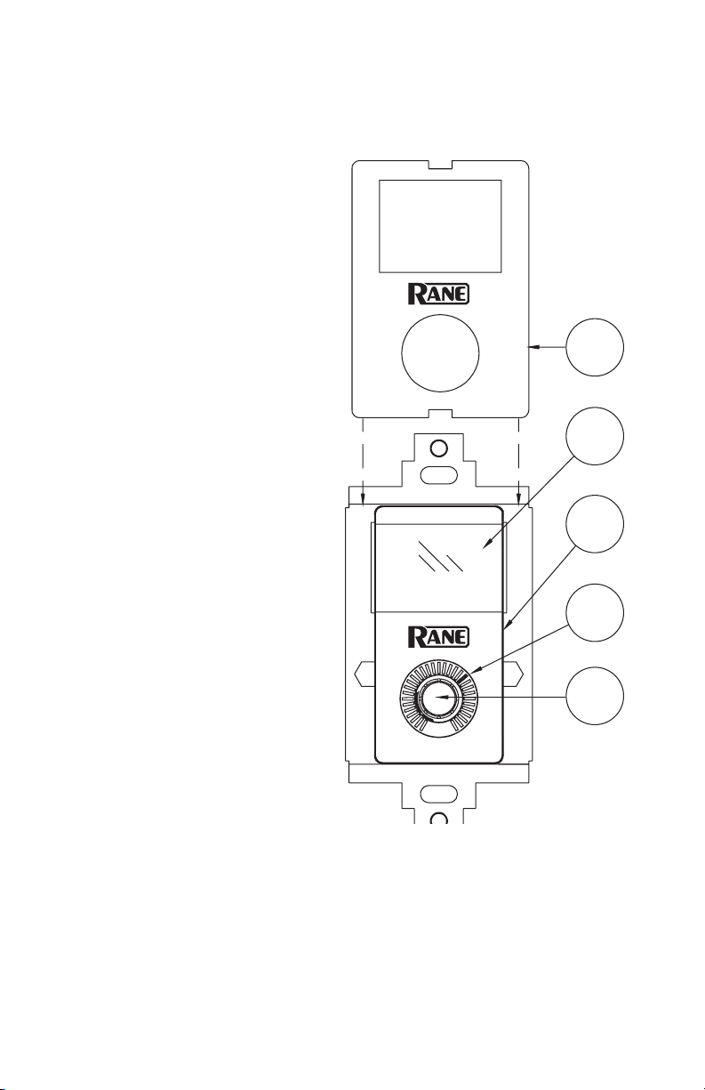
Front Panel Description
1 Colored insert: 4 colors
included: white (w/black logo),
white (w/ almond logo), almond
(w/black logo) and black (w/white
logo).
2 98 x 64 pixel LCD display.
3 Clear lens covers and protects
the LCD display and helps support dierent color templates
which mount behind the lens.
1
4 LED indicators. Indicate the
current “level” of the linked
parameter(s).
5 Encoder Knob with momen-
tary push switch is the user
input to the SR 3.
2
3
4
5
Manual-4
Page 5
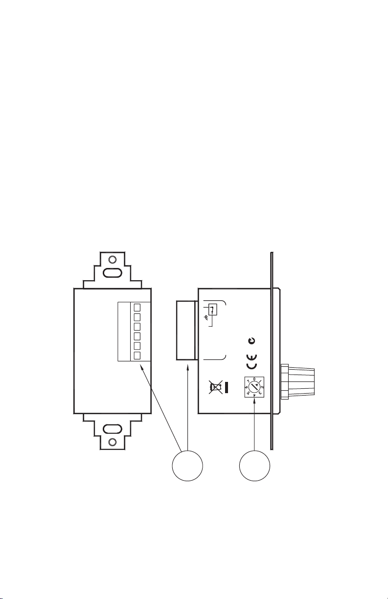
Rear Panel Description
12
ACN 001 345 482 RANE CORP.
REMOTE INTERFACE
PORT
MADE IN U.S.A.
ADDRESS
AB
ENCODER LOCK
+V -V
SR 3
1 Device Address switch assigns the device its RW 485 address. Addresses 0
through 7 are valid.
2 6-wire Euroblock connector. Connects the SR 3 to a controller. A con-
nects to RS-485 data +, B connects to RS-485 data –. +V is the positive
side of the power supply rail. –V is the negative/ground side of the power
supply rail. Ground is the connection point for the shield when shielded
cable is used. When the Encoder Lock pin is grounded and Auto Lock is
enabled, encoder input is ignored by the SR 3. is, for example, allows a
keyed switch to be installed next to the SR 3 that allows the device to be
“locked” so no one could change system volume.
Manual-5
Page 6

Working with Smart Remotes
Smart Remote Overview
Smart Remotes are congured within Drag Net 4 and higher. e following sections describe conguring the various parameters and modes for the
remotes themselves. Details on assigning remotes to control parameters and
functions with an RPM are found in Drag Net’s included Help le (Help >
Help Topics).
Creating a new Conguration
Smart Remote congurations can be created as oine Storage les, for subse-
quent transfer to a Live remote. To create a new Smart Remote Conguration:
1. Click the File menu, choose New, then select Conguration (CTRL + N).
- or - Click the New Conguration button in the standard toolbar.
- or - Right-click within the Project window and select New, then
Conguration (CTRL + N).
2. Select the conguration source, either from an empty conguration, or
from an existing Rane- or User-dened template. Select a device type from
the Conguration Type list to lter the list of le options (to only show
SR 3 les in the User Template directory, for example). Selecting the Copy
Settings check box copies all parameters to the new conguration. is
is a particularly useful feature when creating new congurations based on
existing User Templates.
3. Select a conguration type (SR 2, SR 3, SR 4) from the list of choices.
4. Click Next
5. Enter a Name, storage location on your hard drive, and brief description of
the conguration.
6. Click Finish and start conguring the remote!
File extensions for Smart Remote congurations follow the remote type –
SR 3 congurations are stored as .sr3 les, for example.
Each remote has a number of conguration parameters which determine
basic functions and user operation modes. ese parameters are stored locally
on each remote in non-volatile memory.
Manual-6
Page 7

SR 3 Conguration Parameters
e SR 3 features a 31-position LED indicator, rotary data encoder with
integrated push switch, and a 98 x 64 pixel monochrome LCD display with
a programmable backlight. Up to 16 images (plus a Title Page) are stored lo-
cally in the SR 3 as bitmap pages and automatically recalled to correspond to
dierent system modes.
Create your own bitmaps (.bmp les) using a graphics program such as
Microsoft Paint™, or use any of the images installed automatically with Drag
Net. e RaneSR_3 truetype font contains a number of useful audio/visual
symbols, and is automatically installed with Drag Net.
Auto Lock
Auto Lock is used in conjunction with the remote’s Encoder Lock pin to
disable the SR encoder. When the Encoder Lock pin is grounded and Auto
Lock is enabled, changes in position of the encoder are ignored by the SR.
For example, a keyed switch installed next to the SR allows the device to be
locked temporarily so the system volume can not be adjusted.
Auto Title Page & Page Timer
When Auto Title Page is enabled, the SR 3 automatically reverts to the Title
Page (Page 0) after a user-dened time out. Any adjustment of the encoder
causes the remote to exit Title Page mode and revert back to the most recently
displayed page. Auto Title Page mode is operational even when Auto Lock is
enabled.
e Page Timer determines how long the remote waits after the most
recent change before displaying the title page (Page 0). e valid range for the
timer is 1 to 25 seconds.
Knob Turn
When Auto Level is enabled and the encoder is turned normally (without
pushing it in) the LED moves clockwise or counterclockwise one position in
the direction the knob was turned.
Always enable Auto Level when using a Smart Remote with a Rane RPM
device.
Knob Push & Turn
When Auto Page is enabled and the encoder is held in and turned, the page
stored in the next (or previous) position is automatically loaded into the SR 3
displ ay.
When Page Roll is enabled the page selection wraps around from last
page to rst (or rst page to last, depending on the direction the encoder was
turned).
Manual-7
Page 8

When Update on Release is enabled, the SR updates its Page index when
the encoder is released, rather than updating each time the encoder is turned.
is feature allows users to scroll through and preview pages, select the Page
they want, then release the encoder to trigger the action (for example, recall
Preset on an RPM 88).
Knob Bump
When Auto Page is enabled and the encoder is pressed in and released (with-
out turning), the next Page is automatically loaded into the SR 3 display; the
Page index is updated after the Update Timer expires.
Note: Pages automatically roll from the last page to the rst page while in
Bump mode.
e Update Timer determines how long the SR 3 waits before updating
its Page index once the encoder is released. Setting this value to 0 updates
the Page index instantly, with every press/release combination of the encoder.
Increasing this value allows users to scroll through and preview pages without
updating the Page index on every press.
e valid range for the timer is 0 to 5 seconds.
Min Backlight
Min Backlight sets the desired brightness when the SR 3 is in its default or
resting state, after the backlight timer expires.
Max Backlight
Max Backlight sets the desired brightness when the SR 3 is in its active state.
Backlight Timer
e Backlight Timer determines how long the LCD backlight remains on
after the last change was made. e timer is restarted whenever a change is
made to the push switch or encoder. e valid range for the timer is 1 to 25
seconds.
Max Num Pages
Max Num Pages limits the number of user accessible pages. For example, if
Max Num Pages is set to 4, the user is only able to view Pages 1 through 4,
even though there are 12 other Pages (total of 16) stored on the device. e
SR 3 always displays Page 1 through Max Num Pages unless a value of 0 is
specied. If a value of 0 is specied the title page (Page 0) is displayed upon
power up and the user is unable to change pages.
Max Num Pages only applies when an Auto Page mode is enabled.
Manual-8
Page 9

Working with SR 3 Bitmaps and Pages
Creating Bitmaps
Bitmaps can be created using any third party graphics program, such as
Microsoft Paint™ or Adobe Photoshop™. To get started, a number of useful
images are installed in the Program Files\Rane Corporation\SR\Bitmap director y.
Images must be monochrome (1-bit), 98 pixels wide x 64 pixels high. It is
possible to concatenate multiple images together to form a single, larger im-
age. e concatenated image must be 98 pixels wide by (N * 64) pixels high,
where N is the number of Pages (max 17, including Title Page).
Inserting Bitmaps Into Pages
To insert a bitmap into a Page:
1. Left-click to select the Page to be updated. e selected Page is highlighted.
2. Choose Insert Bitmap (CTRL + F) from the Edit menu.
- or Click on the Insert Bitmap icon on the SR 3 Bar.
- or Right-click on the Page and choose Insert Bitmap.
3. Browse and select the le (.bmp extension) to be inserted.
Bitmaps can also be inserted or moved using standard Windows clipboard
Cut, Copy and Paste operations:
Copy (CTRL - C) - Copies the selected Page bitmap(s) to the Windows
clipboard. ese bitmaps can then be pasted back into the SR Conguration,
or to a graphics program for editing.
Paste (CTRL - V) - Pastes the current contents of the Windows clipboard
to the selected Page(s).
Copy and Paste operations support multiple Page selections. If a Copy
operation is performed while multiple Pages are selected, a single bitmap is
sent to the clipboard as a concatenation of the individually selected bitmaps in
the order they appear from top to bottom in the Page list.
If a Paste operation is performed with a bitmap containing more than one
Page, the Pages in the bitmap are inserted into the Page list one at a time in
order from top to bottom within the selected Pages.
If the number of images in the clipboard doesn’t match the number of selected Pages, the Paste operation matches the rst image in the clipboard with
the top-most selected item, continuing in this fashion until either all images
in the clipboard are used or the last selected Page is reached.
Manual-9
Page 10

Re-ordering Pages
To move bitmaps between adjacent Pages:
1. Select the Page to be moved.
2. Choose Move Up or Move Down from the Edit menu
- or Right-click on the Page and choose Move Up or Move Down.
Move Up (CTRL - ) swaps bitmaps with the Page immediately above
the currently selected Page. Move Down (CTRL - ) swaps bitmaps with the
Page immediately below the currently selected Page. Only one Page at a time
can be selected and moved.
Synchronizing Pages Between the PC and SR 3
By transferring from Storage to Live
Bitmaps on the remote are automatically updated in the destination (Live
remote or Storage SR 3 conguration) when any method described in Tra nsferring Congurations to and from a Live Remote is used. is feature can
be disabled as a user preference (Tools > Preferences > SR Devices).
When working with a Live remote
Double-clicking a remote listed under the Live folder of the Project window automatically opens the remote for parameter adjustment. e bitmap
images currently in the remote are immediately loaded for viewing and editing within Drag Net.
Inserting a bitmap using any of the means described in the Inserting Bitmaps Into Pages section automatically overwrites the remote’s current image
with the new image.
You can also select any page or pages and choose Get Selected from Drag
Net’s SR 3 Toolbar (View > SR 3 Bar) or the right-click context menu.
Manual-10
Page 11

Fonts
Since the SR 3 supports displaying strings on the LCD display, two types of
fonts are stored in read-only memory. e two types of fonts are text and symbol. e text font allows the host controller to send ASCII character strings to
the display in three dierent sizes. e symbol font allows the host controller
to send ASCII characters to the SR 3 that are displayed as simple icons in two
dierent sizes. e symbol font is useful when the end users of the SR 3 are
better served by graphics rather then text such as bilingual applications. When
needed, one can load bitmaps with foreign language characters using MS
Paint and save them in the LCD pages.
A few notes about the built-in fonts. Small font characters are 1 line tall,
medium font characters are 2 lines tall, and large font characters are 3 lines
tall. is is true for the medium and large symbol font icons as well. e LCD
display consists of 8 lines, therefore when using small characters, 8 total lines
are displayable; when using medium characters or icons, 4 lines t on the
LCD display; and when using large characters or icons, 2 lines t on the LCD
displ ay.
e protocol and communications details for the text and symbol fonts
are found in the section on Communications. e ASCII character to symbol
icon map is detailed on the next page. A hint: load a graphic image into the
display, then use the STR, SL, SR, or SC commands to overlay the fonts on
top of the graphic image.
Manual-11
Page 12

Manual-12
Kr
yeKrahCyeKrahCye
!
!
$
0
3
6
9
<
?
B
E
H
K
N
Q
T
W
Z
c
o
u
x
~
$
'
'
*
*
-
-
0
3
6
9
<
?
B
E
H
K
N
Q
T
W
Z
]
]
`
`
c
f
f
i
i
l
l
o
r
r
u
x
{
{
~
"
"
%
+
4
=
@
C
F
L
O
R
U
X
^
a
d
g
m
p
s
v
y
%
(
(
+
.
.
1
1
4
7
7
:
:
=
@
C
F
I
I
L
O
R
U
X
[
[
^
a
d
g
j
j
m
p
s
v
y
|
|
ahC
#
&
2
5
8
>
A
D
G
M
P
S
V
Y
_
b
e
h
k
n
q
w
#
&
)
)
,
,
/
/
2
5
8
;
;
>
A
D
G
J
J
M
P
S
V
Y
\
\
_
b
e
h
k
n
q
t
t
w
z
}
z
}
Page 13

Polling for Remotes
Ethernet versus Serial Communication
If Smart Remotes are connected to an RPM device, the RPM acts as a data
bridge, allowing communication with the remote through the Ethernet connection to the RPM. Smart Remotes appear beneath the RPM device in the
Live folder of the Project window.
Serial communication takes place through the PC’s COM port, which is
usually RS-232 and therefore must be connected to the SR using an RS-232
(unbalanced data) to RS-485 (balanced data) converter capable of supporting
the desired baud rate. Select the COM port connected to the SR from the list
of available ports when polling for Live devices.
Baud Rate
e Baud Rate can only be set when Serial Mode is selected during polling.
When conguring Remotes used with Rane controllers (RPM 88/44/22), the
RW 485 baud rate of 38400 bps is automatically set. Should you encounter
communication problems, settings can be restored to 38400 baud, 10 ms delay by holding the encoder in while powering the remote. Release the encoder
when its LED lights.
Transferring Congurations to and from a Live Remote
Remotes can be congured oine in Storage mode, then transferred to a Live
remote when you get to the job site. Alternately, you can transfer the contents
of a Live remote to an oine Storage conguration as a backup, or for editing
when you’re back in the comfy chair at the oce.
Storage to Live
Live remotes are initialized by transferring a Storage conguration to a Live
remote. is action replaces all settings on the remote. Once the transfer is
complete, you can continue to work directly with the Live remote, adjusting
mode parameters, inserting bitmaps (SR 3), and so on. Hint: You’ll need to
Poll for Live devices before transferring congurations. To transfer a Storage
remote conguration to a Live device:
1. Toggle the Project Window on if it’s not already visible (View > Project).
2a. Drag and drop the Storage conguration listed under the Storage folder
onto a destination remote listed under the Live folder.
- or 2b. Select the Storage conguration, click the Transfer Cong To button,
and then select a destination remote from the list.
- or 2c. Right-click the Storage conguration and choose Transfer To, then select
a destination remote from the list.
Manual-13
Page 14

Live to Storage
Important: Transferring from a Live remote to an existing Storage congura-
tion overwrites the Storage conguration.
To transfer from a Live remote to a Storage conguration:
1. Toggle the Project Window on if it’s not already visible (View > Project).
2a. Drag and drop the Live remote onto an existing destination Storage con-
guration.
- or -
2b. Select the Live remote, click the Transfer Cong To button, and then
select a destination Storage conguration from the list, or choose to create
a new conguration.
- or -
2c. Right-click the Live remote and choose Transfer To, then select the
destination Storage conguration from the list, or choose to create a new
conguration.
Editing a Live Remote
It is possible to edit any parameter on a Live remote directly, without rst having to transfer a Storage conguration to it.
To view the current contents of a Live remote simply double-click the
remote listed under the Live folder of the Project Window. Alternately, rightclick the Live remote and choose Open item. e contents of the Live remote
are then loaded into the Device Conguration window for viewing and/or
editing.
Renaming a Remote
To rename a Smart Remote:
1. Right-click the Live remote in the Project window and choose Properties.
2. Enter a new name for the remote in the Name eld.
Manual-14
Page 15

Updating Smart Remote Firmware
It may be necessary to update a Smart Remote’s rmware in order to add
features or address one of those pesky glitches that only seem to appear after
the product’s been released.
Remotes with the following rmware versions can be upgraded as new
rmware becomes available:
Remote With Firmware Version
SR 2 2.0 and higher
SR 3 4.0 and higher
SR 4 1.0 and higher
Older remotes may not be updateable, or updateable only by Rane. Contact
Rane Tech Support 425-355-6000 or visit www.rane.com to email us for
more information.
Firmware les for all remotes are installed as part of Drag Net and are
located in the Program Files\Rane Corporation\Drag Net\Firmware\Smart
Remotes directory.
To update rmware in a Smart Remote:
1. Ensure remotes are properly connected to the RPM device. Remotes must
be connected before powering the RPM on.
2. Connect directly to the RPM device, using an Ethernet crossover cable.
3. Poll to nd the Live device. Remotes are listed beneath the RPM device in
the Project window.
4. Select the Remote to be updated.
5. Launch the Update Device Firmware Wizard (Tools > Update Device
Firmware).
6. Follow the wizard’s on-screen instructions to complete the operation. e
device automatically resets itself once the update is complete.
Firmware updates performed using a COM Port (Serial) follow the exact same
steps, beginning with Step 3.
Manual-15
Page 16

SR 3 Wiring Guidelines
Restrictions
24 AWG CAT 5 cable resistance = 26 ohms per 1,000 feet. ere are two wiring restrictions. First, RW 485 has a maximum of 1,000 feet. e total length
may not exceed this limit in any combination of series or parallel runs.
Second, the voltage of the power supply also aects the maximum
distance of each length between, and the number of Remotes. Refer to the
tables on the following pages depending on which wire, voltage, number of
Remotes, and if you are using single or multiple runs.
External Power Supply
e RPM 88’s RW 485 port does not oer enough current to power more
than three SR 3 remotes — an external DC supply must be used. Rane recommends using a 12 to 15 volt DC regulated power supply capable of deliver-
ing a minimum of 1 amp of current. e combined current draw on the RPM
88’s RW 485 port and VOP cannot exceed 375 milliamps. [e RPM 44 and
RPM 22, however, can power up to eight SR 3 remotes.]
Most installations will have a mix of SR 2, SR 3, and SR 4 remotes each
with their own current requirements. To make calculation easy as to whether
or not an external supply is necessary, a Microsoft Excel™ spreadsheet is
available named SRXCABLELENGTH.XLS. is le is on the Drag Net
CD-ROM, or downloadable from www.rane.com/smart.html.
If you have a Radio Shack nearby, they oer a 15 volt 1 amp supply, cata-
log number: 273-1691. To ease installation, use a 6 foot Adaptaplug extension
cable, Radio Shack catalog number 273-1641.
Manual-16
Page 17

12 to 15 VDC
regulated
power
supply:
Radio Shack
273-1691
or equivalent.
Radio Shack
273-1641
Adaptaplug
TIP
REMOTE INTERFACE PORT
To more SR Remotes
RPM 88
AB+V -V
(RW 485)
0
2
7
1
6
5
4
3
RANE CORP.
REMOTE INTERFACE
White stripe = (+)
PORT
MADE IN U.S.A.
AB
ENCODER LOCK
+V -V
SR
ACN 001 345 482
ADDRESS
Manual-17
Page 18

REGULATED
POWER
SUPPLY
Single Run Distance (Series)
Multiple Run Distances (Star)
REMOTE INTERFACE PORT
RPM
AB+V
-V
(RW 485)
REGULATED
POWER
SUPPLY
REMOTE INTERFACE PORT
RPM
AB+V
-V
(RW 485)
d1
d1
d2
d2
d3
d3
dT
Cable Type 1
2 twisted pair unshielded CAT 5, Belden #1588(A,R)
2 twisted pair unshielded CAT 5, Belden #1590A
Single run restriction: Total cable length
d1+d2+d3 = dT ≤468 ft (per table example)
Manual-18
Page 19

Cable Type 1
2 twisted pair unshielded CAT 5, Belden #1588(A,R)
2 twisted pair unshielded CAT 5, Belden #1590A
Max Distance
for Cable (feet)
Vs = 15V
RPM 44
RPM 22
Vs = 12V
RPM 88
Requires
external
supply
Vs = 8V 149 45 1
1000 305 1
672 205 2
468 143 3
359 109 4
291 89 5
245 75 6
211 64 7
186 57 8
745 227 1
420 128 2
292 89 3
224 68 4
182 55 5
153 47 6
132 40 7
116 35 8
84 26 2
58 18 3
45 14 4
36 11 5
31 9 6
26 8 7
23 7 8
Max Distance for
Cable (meters)
Number of
SR 3 Remotes
Note: This table is only for systems using SR 3 remotes (all remotes on 485 bus are
the same). For mix and match calculation of SR 2, SR 3 and SR 4 Remotes, use the
SRCABLELENGTH.XLS Microsoft Excel™ spreadsheet on the Drag Net CD-ROM or
at www.rane.com/sr3.html.
Manual-19
Page 20

REMOTE INTERFACE PORT
RPM
AB+V
-V
(RW 485)
Cable Type 1
Multiple run restriction (per table entries): d1 ≤468 ft, d2 ≤672 ft, d3 ≤1,000 ft
Total cable length must be under 1,000 ft: d1 + d2 + d3 = dT ≤1,000 ft
Examples:
So if
d1=400 ft (<468 ft, OK)
d2=300 ft (<672 ft, OK)
d3=200 ft (<1,000 ft, OK)
d1+d2+d3=900 ft, then it's all OK!
BELDEN #1588 (A,R)
BLUE
ORANGE
WHITE/BLUE
WHITE/ORANGE
but if
d1=400 ft (<468 ft, OK)
d2=500 ft (<672 ft, OK)
d3=300 ft (<1,000 ft, OK)
d1+d2+d3=1,200 ft, then it's NOT OK!
BELDEN #1590 (A)
BLUE
WHITE/BLUE
ORANGE
WHITE/ORANGE
ADDR ES S
ADDRESS 0
4
Manual-20
-V+VA B
ENCOD E R LOC K
RE MO TE INTER FAC E
PO RT ( RI P)
6
7
5
0
1
3
2
S R S R S R
MADE IN U.S.A .
RAN E CO R P.
ADDR ES S ADDR ES S
5
ADDRESS 1
4
3
6
2
7
0
1
+VA B -V
ENCOD E R LOC K
RE MO TE INTER FAC E
PO RT ( RI P)
MADE IN U.S.A .
RAN E CO R P.
6
7
5
ADDRESS 7
0
4
1
3
2
+VA B -V
ENCOD E R LOC K
RE MO TE INTER FAC E
PO RT ( RI P)
MADE IN U.S.A .
RAN E CO R P.
Page 21

Cable Type 2
REGULATED
POWER
SUPPLY
Single Run Distance (Series)
Multiple Run Distances (Star)
REMOTE INTERFACE PORT
RPM
AB+V
-V
(RW 485)
REGULATED
POWER
SUPPLY
REMOTE INTERFACE PORT
RPM
AB+V
-V
(RW 485)
d1
d1
d2
d2
d3
d3
dT
4 twisted pair unshielded CAT 5, Belden #1583(A, B, E, ENH, R)
4 twisted pair shielded CAT 5, Belden #1624 (P, R)
4 twisted pair unsheilded CAT 5, Belden #1700 (A, R)
Single run restriction: Total cable length
d1+d2+d3 = dT ≤1,000 ft (per table example)
Manual-21
Page 22

Cable Type 2
4 twisted pair unshielded CAT 5, Belden #1583(A, B, E, ENH, R)
4 twisted pair shielded CAT 5, Belden #1624 (P, R)
4 twisted pair unsheilded CAT 5, Belden #1700 (A, R)
Max Distance
for Cable (feet)
Vs = 15V
RPM 44
RPM 22
Vs = 12V
RPM 88
Requires
external
supply
Vs = 8V 447 136 1
1000 305 1
1000 305 2
1000 305 3
1000 305 4
872 266 5
734 224 6
633 193 7
557 170 8
1000 305 1
1000 305 2
877 267 3
672 205 4
545 166 5
459 140 6
396 121 7
348 106 8
252 77 2
175 53 3
134 41 4
109 33 5
92 28 6
79 24 7
70 21 8
Max Distance for
Cable (meters)
Number of
SR 3 Remotes
Note: This table is only for systems using just SR 3 remotes (all remotes on 485
bus are the same). For mix and match calculation of SR 2, SR 3 and SR 4 Remotes,
use the SRCABLELENGTH.XLS Microsoft Excel™ spreadsheet on the Drag Net CDROM or at www.rane.com/sr3.html.
Manual-22
Page 23

Cable Type 2
REMOTE INTERFACE PORT
RPM
AB+V
-V
(RW 485)
More conductors mean greater operating distance.
Multiple run restriction (per table entries): d1 ≤1,000 ft, d2 ≤1,000 ft, d3 ≤1,000 ft
Total cable length must be under 1,000 ft: d1 + d2 + d3 = dT ≤1,000 ft
Examples:
So if
d1=400 ft (<1,000 ft, OK)
d2=300 ft (<1,000 ft, OK)
d3=200 ft (<1,000 ft, OK)
d1+d2+d3=900 ft, then it's all OK!
but if
BLUE
GREEN
BROWN
WHITE/ORANGE
*SHIELD
WHITE/GREEN
WHITE/BROWN
ORANGE
WHITE/BLUE
d1=500 ft (<1,000 ft, OK)
d2=400 ft (<1,000 ft, OK)
d3=300 ft (<1,000 ft, OK)
d1+d2+d3=1,200 ft, then it's NOT OK!
BELDEN #1583 (A, B, E, ENH, R)
BELDEN #1624 (P, R) *Shielded
BELDEN #1700 (A, R)
BLUE
WHITE/BLUE
ORANGE
WHITE/ORANGE
GREEN
BROWN
WHITE/GREEN
ADDR ES S
ADDRESS 0
5
4
3
WHITE/BROWN
*SHIELD
6
7
0
1
2
-V+VA B
ENCOD ER LOC K
RE MOTE I NTER FAC E
PO RT ( RI P)
S R S R S R
MADE IN U.S.A .
RANE CO RP.
ADDR ES S ADDR ES S
ADDRESS 1
+VA B -V
ENCOD ER LOC K
RE MOTE I NTER FA CE
PO RT ( RI P)
6
7
5
0
4
3
2
MADE IN U.S.A .
1
RANE CO RP.
ADDRESS 7
6
7
5
0
4
1
3
2
+VA B -V
ENCOD ER LOC K
RE MOTE I NTER FAC E
PO RT ( RI P)
MADE IN U.S.A .
RANE CO RP.
Manual-23
Page 24

SR 3 Communication Protocol
e SR 3 communication protocol follows Rane’s RW 485 specication. e following describes the SR 3 implementation.
Physical
e baud rate is 38,400 bps with No parity, 8 Data Bits, 1 Stop Bit (N81) format. e
SR 3 also supports 9600, 19200, 57600, and 115200 bps. When conguring Remotes
used with Rane controllers (RPM 22, 44, 88), the RW 485 baud rate of 38400 bps is
required. At the end of a command message, the Master must release the bus within
10 ms. e SR 3 waits this length of time before transmitting its response. To restore
the SR 4 communication settings to 38400 baud 10 ms delay, apply power while
pushing the encoder in for several seconds until “COMM RESTORED” is displayed
on the LCD.
Master/Slave
RW 485 is a master/slave bus network, with only one master in charge, which we dene as the Protocol Master (controller). When the Protocol Master expects a response
from a slave, it relinquishes control of the bus, allowing the slave to drive the RS-485
bus. e slave must then release the bus back to the Protocol Master, and we start
again. e SR 3 is always a slave.
Value Encoding
All numeric values are represented in ASCII decimal format separated by commas,
except LCD data which are represented in ASCII hex (2 characters per byte, no
commas). Values with the MSB set ($80 or larger) are interpreted as potential device
addresses.
Syntax
Command messages are sent from the Protocol Master to the SR 3. Response messages are returned to the Protocol Master from the SR 3. e SR 3 always responds to
the Protocol Master upon receiving a complete command message at the correct baud
rate.
Command and response messages have the same format:
message = <addr> <msgtype> <devtype> <checksum> <command/data>
<CR>
<addr> Each device has a unique address in the range [0, 7]. e encoding is one
byte with the MSB set.
For example, if the SR 3’s address switch is set to 5, the controller would send
10000101.
Manual-24
Page 25

e SR 3 always returns its address switch setting plus $80.
Note: Upon power-up of the SR 3, a status screen is displayed on the LCD display
that reports the switch setting. In rmware version >2.1, the status screen also displays
the rmware version and can be displayed any time by holding the encoder in for six
seconds. e status screen is displayed until the encoder is released. is feature is not
aected by the hardware lock, although it can be defeated by the software lock. See
ILK command in the SR 3 Command Set for details.
<msgtype> e msgtype is a one byte set of ags indicating options, bit 7=MSB:
bit 0) set = checksum is valid
bit 1) set = there has been an error (response only)
bit 2-5) reserved, cleared to 0
bit 6) always 1
bit 7) always 0
If the controller wants the SR 3 to verify the checksum, it would send a value of
$41, or an ASCII ‘A’. If the controller wants the SR 3 to ignore the checksum, it would
send a value of $40, or an ASCII ‘@’. e SR 3 echoes back the <msgtype> it was
sent. In the case of an error, the SR 3 sets bit 1.
<devtype> e SR 3 device type value is $31, or an ASCII ‘1’. e SR 3 also ac-
cepts a value of $30, or an ASCII ‘0’, the universal device type used for polling. e
SR 3 always returns its device type of $31.
<checksum> e checksum is dened as the sum of the ASCII encoded values of
the <command/data > section. e sum is then masked with $007F to produce one
byte with the MSB set to zero.
e controller would send a valid checksum as dened above if it sent a value of
$41 for the <msgtype>. e SR 3 then veries the sent checksum by calculating the
checksum from the data it received in the <command/d ata> section of the sent message. On the other hand, if the controller sent a value of $40 for the <msgtype> the
SR 3 ignores the sent checksum. e controller must always send a checksum less than
or equal to $7F, even if it intends for the SR 3 to ignore it.
e SR 3 <checksum> response is based on the <msgtype> it was sent. If the SR
3 received a <msgtype> of $41, it returns a valid checksum (as dened) calculated
from it’s response data. If the SR 3 received a <msgtype> of $40, it returns zero.
<comma nd/data> e general format is <cmd1,arg1,arg2,…,cmd2,arg1,…>. e
commas are part of the <command/data> structure and act as delimiters between the
ASCII encoded commands and data. Text string arguments are delimited with quotes
("String"). If the string argument contains quotes, an accent character (') placed in
the string argument will be interpreted by the SR 3 as a double quote character (").
e ASCII value for the accent char is $60, not to be confused with a single quote
character ('), ASCII value $27. For example: string argument: "A string that contains
'quotes'" is interpreted as: A string that contains "quotes".
Manual-25
Page 26

e controller sends commands/arguments for the SR 3 to process. is section
of the message is limited to 250 characters for the SR 3. See the SR 3 Command Set
section for details of valid commands.
e SR 3 responds with response data based on the commands/arguments it was
sent. e SR 3 limits its response data to 250 characters. In the case of an error, the
response data is: n,"ERROR" where n is an error code dened below:
Hex ASCII Error Code Meaning
$31 '1' Sent <devtype> invalid.
$32 '2' Sent <checksum> did not verify.
$33 '3' Sent <comma nd/data> parse error.
$34 '4' Sent <comma nd/data> greater than 250 characters.
$35 '5' Response <comma nd/data> greater than 250 charac-
ters.
See the SR 3 Command Set section below for details of valid SR 3 responses.
<CR> A carriage return ($0D) terminates every message.
SR 3 Command Set
is section details the <comma nd/data> portion of a complete RW 485 mes-
sage. e SR 3 supports 25 commands. Below is a table of commands and associated
responses, followed by descriptions.
Conguration Commands
Cmd Arg(s)* Description Response**
V Get Firmware, Hardware Version n1,n2,"OK"
N ["ccc…"] Read/Write Device's Name "ccc…","OK"
SPL n1[,n2] Read/Write Stored Parameter n,"OK"
Display Commands
BL n1 Backlight O/On "OK"
BMP n1 Display ROM based Bitmap "OK"
CLS Clear Screen "OK"
CLL n1 Clear Line "OK"
RVL n1 Reverse Line "OK"
FNT n1 Select Font "OK"
MC n1,n2 Move Cursor "OK"
XDR n1 Read Hex Data from LCD xxxx,"OK"
XDS n1,xxxx… Send Hex Data to LCD "OK"
STR "ccc…" String "OK"
SL n1,"ccc…" String Left "OK"
SC n1,"ccc…" String Center "OK"
SR n1,"ccc…" String Right "OK"
PS n1 Page Select "OK"
PW n1 Page Write "OK"
Input Commands
ILD [n1] Get/Set LED n1,"OK"
ILK [n1] Read/Write Input Lock n1,"OK"
IQ Input Query n1,n2,"OK"
Manual-26
Page 27

IR Input Raw n1,n2,n3,n4,"OK"
IS n1,n2 Input Suggest n1,n2,"OK"
ISR n1,n2 Input Suggest Raw n1,n2,n3,n4,"OK"
IF n1,n2 Input Force "OK"
* [ ] denotes optional Command Argument
** Responses from concatenated commands produce only one "OK"
Conguration Commands
V
Get Firmware, Hardware Version
Send: V
Response: n1,n2,"OK"
Where: n1 is a two digit ASCII encoded decimal value
representation of the rmware version. e rst digit is
the major rmware version and the second digit is the
minor rmware version.
n2 is a one digit ASCII encoded decimal value
representation of the hardware version.
Example: 13,2,"OK" means rmware version 1.3, hardware
version 2.
N
Read/Write Device's Name
e device’s name is limited to 32 characters and is stored in non-volatile memory.
e default name is SR 3.
To read the device’s name:
Send: N
Response: "ccc","OK"
Where: ccc is the device’s name.
Example: "SR 3","OK" means the device’s name is SR 3
To write a new name to the device:
Send: N,"ccc"
Where: ccc is the new name.
Example: N,"Conference Room 101" will rename the device to
Conference Room 101
Response: "OK"
SPL
Read/Write Stored Parameter
Various conguration parameters are stored in non-volatile memory. is command
reads and writes these parameters. For details of each parameter, see the Stored Parameter List section following the Command Set section.
Manual-27
Page 28

To read a stored parameter value:
Send: SPL,n1
Where: n1 is the stored parameter index.
Example: SPL,7 indexes the seventh parameter in the list which is
the Auto Level parameter.
Response: n1,"OK"
Where: n1 is the value of the indexed parameter.
Example: 1,"OK" means that Auto Level is enabled.
To write a stored parameter value:
Send: SPL,n1,n2
Where: n1 is the stored parameter index.
n2 is the value to be stored.
Example: SPL,7,0 sets Auto Level parameter to 0, disabling the
Auto Level function.
Response: "OK"
LCD Display Commands
BL
Back light O/On
Toggles the LCD back light from maximum brightness setting to minimum bright-
ness setting and vice-versa. See the Stored Parameter List section for further details on
back light conguration.
Send: BL,n1
Where: n1 is the back light ag
Example: BL,1 sets the back light brightness to the maximum
brightness specied by the back light maximum
conguration and starts the back light timer. After the
timer expires, the back light brightness fades to the
minimum brightness specied by the back light
minimum conguration and the back light ag is
cleared. BL,0 clears the back light ag and causes the
back light brightness to immediately fade to the
minimum brightness specied by the back light
minimum conguration.
Response: "OK"
Manual-28
Page 29

BMP
Display ROM based Bitmap
Displays the specied read-only bitmap. See Appendix B for room combining images.
Se n d : BMP, n1
Where: n1 is the bitmap index. Bitmap image 0 is the Rane
splash screen and bitmap images 1-17 are the default
images used to initialize pages 0-16. Bitmap images 18
to 41 are the room combining images.
Example: BMP,1 transfers the ROM based image 1 to the LCD.
Response: "OK"
CLS
Clear Screen
Clears the LCD image data and resets the cursor position to (0, 0).
Send: CLS
Response: "OK"
CLL
Clear Line
Clears the LCD image data on the specied line.
Send: CLL,n1
Where: n1 is t he line number to be cle ared. n1 range s from 0 to 7.
Line 0 is the bottom line.
Example: CLL,1 clears the second line from the bottom.
Response: "OK"
RVL
Reverse Line
Reverses the LCD black/white image data on the specied line.
Send: RVL,n1
Where: n1 is the line number to be reversed. n1 ranges from 0 to 7.
Line 0 is the bottom line.
Example: RVL,0 reverses the black/white image data of the
bottom line.
Response: "OK"
FNT
Select Font
Selects the font used by string commands. Small fonts are one line tall, medium fonts
are two lines tall, large fonts are three lines tall. Font 0 is the small alphanumeric font,
font 1 is the medium alphanumeric font, font 2 is the large alphanumeric font, font 3
is the medium symbol font, and font 4 is the large symbol font.
Send: FNT,n1
Where: n1 is the font index. n1 ranges from 0 to 4.
Example: FNT,2 selects the large alphanumeric font.
Response: "OK"
Manual-29
Page 30

MC
Move Cursor
Moves the cursor to (x, y) location, where x is the x-axis location ranging from 0
through 97 (one pixel width) and y is the y-axis location ranging from 0 through 7
(eight pixel height). Cursor position (0, 0) is the lower left corner of the display. For a
visual description, see Appendix A at the end of this document.
Send: MC,n1,n2
Where: n1 is x-location ranging from 0 through 97
n2 is the y-location (or line number) ranging from 0
through 7.
Example: MC,8,5 moves the cursor to x-location 8 (9 pixels from
the left), y-location 5 (6 lines from the bottom).
Response: "OK"
XDR
Hex Data Read
Reads Hex Data from the LCD starting from the current cursor location and proceed-
ing left to right. Bytes are represented in two ASCII characters per byte. Since the
width is known, no commas are used for delimiting values. e format of the data
bytes is shown in Appendix A at the end of this document.
Send: XDR,n1
Where: n1 is the number of bytes to read. e range is [1, 98].
Example: XDR,4 will read four bytes of LCD data starting at the
current cursor location.
Response: xxxx,"OK"
Where: xxxx is the ASCII Hex representation of the LCD data.
e range is [00, FF].
Example: 03693F2B,"OK" means that the four bytes requested
starting from the current cursor position and
proceeding from left to right are
03 or 0000 0011
69 or 0110 1001
3F or 0 011 1111
2B or 0010 1011
For byte to pixel interpretation, see Appendix A at the end of this document.
XDS
Hex Data Send
Sends Hex Data to the LCD starting from the current cursor location and proceeding
left to right. Bytes are represented in two ASCII characters per byte. Since the width
is known, no commas are used for delimiting values. e format of the data bytes is
shown in Appendix A at the end of this document.
Send: XDS,n1,xxxx
Where: n1 is the number of bytes to send. e range is [1, 98].
xxxx is a list two ASCII character per byte
representation of the bytes to send.
Example: XDR,4,03693F2B will send four bytes of LCD data
to the display starting at the current cursor location.
Manual-30
Page 31

e four bytes are:
03 or 0000 0011
69 or 0110 1001
3F or 0 011 1111
2B or 0010 1011
For byte to pixel interpretation, see Appendix A at the end of this document.
Response: "OK"
STR
String
Displays a string using the current font starting at the current cursor location.
Send: STR,"ccccc"
Where: ccccc is the string of characters to be displayed
Example: STR,"Hello World" displays the string: Hello World.
Response: "OK"
SL
String Left
Displays a left justied string using the current font on the specied line.
Send: SL,n1,"ccccc"
Where: n1 is the line number for the string to be displayed on.
n1 ranges from 0 (bottom line) to 7 (top line).
ccccc is the string of characters to be displayed.
Example: SL,3,"Hello World" displays the left-justied string:
Hello World
Response: "OK"
SC
String Center
Displays a center justied string using the current font on the specied line.
Send: SC,n1,"ccccc"
Where: n1 is the line number for the string to be displayed on.
n1 ranges from 0 (bottom line) to 7 (top line).
ccccc is the string of characters to be displayed
Example: SC,3,"Hello World" displays the center-justied string:
Hello World
Response: "OK"
SR
String Right
Displays a right justied string using the current font on the specied line.
Send: SR,n1,"ccccc"
Where: n1 is the line number for the string to be displayed on.
n1 ranges from 0 (bottom line) to 7 (top line).
ccccc is the string of characters to be displayed
Example: SR,3,"Hello World" displays the right-justied string:
Hello World
Response: "OK"
Manual-31
Page 32

PS
Page Select
Displays the associated bitmap image on the LCD display. If either Auto Page is
enabled (“Knob Push & Turn” or “Knob Bump”), the page index is updated as well.
Page 0 is the user title page which is not accessible from encoder input. Pages 1-16 are
accessible from encoder input.
Send: PS,n1
Where: n1 is the requested page index. n1 ranges from 0 to 16.
Example: PS,3 displays the page 3 bitmap image. If either Auto
Page is enabled, the page index is updated to 3.
Response: "OK"
PW
Page Write
Writes the current LCD bitmap image to the indexed page memory.
Send : P W, n1
Where: n1 is the page index. n1 ranges from 0 through 16.
Example: PW,0 stores the current LCD image data to page 0 (the
title page).
Response: "OK"
Encoder Input Commands
ILD
Get/Set LED
Gets or sets the LED indicator status.
To get the LED indicator status:
Send: ILD
Response: n1,"OK"
Where: n1 is the LED status. e status range is [0, 1].
Example: 1,"OK" means that the LED is on.
To set the LED indicator status:
Send: ILD,n1
Where: n1 is the LED status. e status range is [0, 1].
Example: ILD,0 turns the LED o.
Response: "OK"
ILK
Read/Write Software Input Lock
Reads or writes the input encoder software lock byte.
e software lock is used to lock out separate encoder actions and other features. e
format of the lock byte is bit wise where bit set (1) locks the corresponding action, bit
clear (0) unlocks the corresponding action. e lock byte is volatile and is cleared to
zero on power up.
e bit denitions are as follows: bit 0 (LSB) controls the resulting action of
turning the encoder, bit 1 controls the resulting action of turning the encoder while it
is pushed in, bit 2 controls the resulting action of pushing and releasing the encoder
(bump), bit 3 controls the Auto Title Page feature, bit 4 controls the Rane splash
Manual-32
Page 33

screen feature, bits 5 and 6 are don’t cares, bit 7 (MSB) is always zero. e acceptable
range of the Software Input Lock byte is rmware version specic. For version 2.1 and
later the range is 0 through 127. For version 2.0 and 1.1, the range is 0 through 7. For
version 1.0, the range is 0 through 3.
To read the Software Input Lock byte:
Send: ILK
Response: n1,"OK"
Where: n1 is the Software Input Lock byte.
Example: 3, "OK" means that bit 0 and bit 1 are set so the
resulting actions of turning the encoder and of turning
the encoder while it is pushed in are locked.
To write the Software Input Lock byte:
Send: ILK,n1
Where: n1 is the Software Input Lock byte.
Example: ILK,2 locks the resulting action of turning the encoder
while it is pushed in.
Response: "OK"
IQ
Input Query
Returns the current level and page index. Resets the command state byte to No
Operation.
Send: IQ
Response: n1,n2,"OK"
Where: n1 is the current level. e level range is [1, 31].
n2 is the current page index. e page index range is
[0, 16].
Example: 15,4,"OK" means that the current level is 15 and the
current page index is 4.
IR
Input Raw
Returns the current level, page index, command state byte, and the length of time the
encoder button has been pressed. Resets the command state to No Operation.
Send: IR
Response: n1,n2,n3,n4,"OK"
Where: n1 is the current level. e level range is [1, 31].
n2 is the current page index. e page index range is
[0, 16].
n3 is the current command state byte. e command
state byte represents the state of the encoder.
e possible states follow:
0 No Operation e encoder has not changed.
1 Encoder Left e encoder has been turned counter clockwise.
2 Encoder Right e encoder has been turned clockwise
16 Selection Left e encoder has been pushed in and turned counter clockwise.
32 Selection Right e encoder has been pushed in and turned clockwise.
64 Enter e encoder has been pushed in and released without being turned.
Manual-33
Page 34

n4 is the length of time the encoder button has been pressed. e time the button has
been pressed is in units of .01 seconds and the range is [0, 255] or 0 to 2.55 seconds.
e button timer starts at the press of the button and is reset to zero when the button
is released.
Example: 1,2,32,100,"OK" means the current level is 1, the
c ur r e nt pa g e in d e x i s 2, th e e nc od e r ha s b e en p us h ed i n
and turned clockwise, and the button has been held in
for 1 second.
IS
Input Suggest
Suggests new level and page index. Resets the command state byte to No Operation.
If Auto Level is enabled, the level is updated and indicated by the LED only if the
device’s level has not changed by someone turning the encoder. Otherwise, if Auto
Level is disabled, the level is updated and indicated by the LED regardless of encoder
input. If either Auto Page is enabled (“Knob Push & Turn” or “Knob Bump”), the
page index is updated and the associated bitmap is displayed only if the device’s page
index has not changed by local encoder action. Otherwise, if neither Auto Page is enabled, the page index is updated but the associated bitmap is not displayed, regardless
of local encoder action.
Send: IS,n1,n2
Where: n1 is the suggested new level. e level range is [0, 31].
If n1 is [0], the level remains unchanged.
n2 is the suggested new page index. e page index
range is [0, 16]. If n2 is [0], the page remains
unchanged.
Use the PS command to force page [0].
Example: IS,3,5 suggests a new level of 3 and a new page index of
5.
Response: n1,n2,"OK"
Where: n1 is the current level. e level range is [1, 31].
n2 is the current page index. e page index range is
[0, 16].
Example: 3,5,"OK" means the current level is 3 and the current
page index is 5. is means the suggested level and
page index were updated. A response of 10,5,"OK"
means the current level is 10 and was last changed by
someone turning the encoder and the current page
index was updated to 5.
ISR
Input Suggest Raw
Same operation as IS Input Suggest, except ISR returns the command state byte and
button time.
Send: ISR,n1,n2
Where: n1 is the suggested new level. e level range is [0, 31].
If n1 is [0], the level remains unchanged.
Manual-34
Page 35

n2 is the suggested new page index. e page index
range is [0, 16]. If n2 is [0], the page remains
unchanged.
Use the PS command to force page [0].
Example: ISR,3,5 suggests a new level of 3 and a new page index
of 5.
Response: n1,n2,n3,n4,"OK"
Where: n1 is the current level. e level range is [1, 31].
n2 is the current page index. e page index range is
[0, 16].
n3 is the current command state byte. e command
state byte represents the state of the encoder.
e possible states follow:
0 No Operation e encoder has not changed.
1 Encoder Left e encoder has been turned counter clockwise.
2 Encoder Right e encoder has been turned clockwise
16 Selection Left e encoder has been pushed in and turned counter clockwise.
32 Selection Right e encoder has been pushed in and turned clockwise.
64 Enter e encoder has been pushed in and released without being turned.
n4 is the length of time the encoder button has been pressed. e time the button has
been pressed is in units of .01 seconds and the range is [0, 255] or 0 to 2.55 seconds.
e button timer starts at the press of the button and is reset to zero when the button
is released. Example: 3,5,0,0,"OK" means the current level is 3, the current page
index is 5, the current command state byte is a No Operation and the button is not
pushed in. is means the suggested level and page index were updated. A response of
3,7,32,100,"OK" means the current level was updated to 3, the current page index is
7 and was last changed by someone pushing in and turning the encoder, the current
command state byte is a Page Right, and a non-zero button time means someone is
still holding the button in.
IF
Input Force
Forces new level and page index. Resets the command state byte to No Operation.
e level is updated and indicated by the LED regardless of Auto Level conguration.
If either Auto Page is enabled (“Knob Push & Turn” or “Knob Bump”), the page index is updated and the associated bitmap is displayed. Otherwise, if neither Auto Page
is enabled, the page index is updated but the associated bitmap is not displayed.
Send: IF,n1,n2
Where: n1 is the new level. e level range is [0, 31]. If n1 is
[0], the level remains unchanged.
n2 is the new page index. e page index range is [0, 16]. If n2 is
[0], the page remains unchanged.
Use the PS command to force page [0].
Example: IF,3,5 sets a new level of 3 and a new page index of 5.
Response: "OK"
Manual-35
Page 36

Stored Parameter List (SPL)
Below is a table of stored parameters followed by descriptions of each parameter.
Index Description Va lue Range Setting Meaning
1 Back light Maximum Brightness 1 - 255 190 0.4 - 100 %
2 Back light Minimum Brightness 1 - 255 1 0.4 - 100 %
3 Back light Timer (.1 sec) 1 - 255 150 0.1 - 25.5 seconds, ignored if SPL 2 >= SPL 1.
4 Auto Page - Knob Push & Turn 0 - 1 1 disabled - enabled
5 Maximum Number of Pages 0 - 16 16
6 Knob Push & Turn Page Roll 0 - 1 0 disabled - enabled, ignored if SPL 4 disabled.
7 Auto Level - Knob Turn 0 - 1 1 disabled - enabled
8 Auto Lock - Hardware 0 - 1 1 disabled - enabled
9 Baud Rate 0 - 4 2 0 = 9600, 1 = 19200, 2 = 38400, 3 = 57600, 4 = 115200
10 RW 485 Transmit Delay (ms) 2 - 200 10 2 - 200 milliseconds
11 Knob Push & Turn Update on Release 0 – 1 1 disabled - enabled, ignored if SPL 4 disabled.
12 Auto Page - Knob Bump 0 – 1 0 disabled - enabled
13 Knob Bump Update Timer (sec) 0 – 5 3 0 - 5 seconds, ignored if SPL 12 disabled. Knob Push & Turn updates take priority over time out.
14 Auto Title Page 0 – 1 0 disabled - enabled
15 Title Page Timer (sec) 1-25 5 1 - 25 seconds, ignored if SPL 14 disabled.
Parameter Descriptions
1. Back light maximum brightness ranges from 1 through 255 and controls the maxi-
mum brightness of the LCD light.
2. Back light minimum brightness ranges from 1 through 255 and controls the mini-
mum brightness of the LCD back light. If the minimum brightness is congured
to a value greater than the maximum brightness, the back light timer is defeated
and the brightness is set to the maximum value.
3. Back light timer conguration ranges from 1 through 255 which corresponds to a
time interval of 0.1 through 25.5 seconds. e back light is illuminated to maxi-
mum brightness when the device is powered up or when the encoder is activated.
e back light stays illuminated at the maximum brightness until the back light
time has expired, then the back light fades to the minimum brightness.
4. Auto Page - Knob Push & Turn conguration aects the result of turning the en-
coder while it is pushed in. If this parameter is enabled (a value of 1), the next page
bitmap is displayed based on the conguration of parameters 5 and 6. e page
index is updated based on the conguration of parameter 11. e conguration of
this parameter also aects the commands PS, IS, ISR, and IF. See SR 3 Command Set section for details of how these commands are aected.
5. Maximum Number of Pages congures the number of pages that can be accessed
by the encoder (Knob Push & Turn and/or Knob Bump). is parameter is ig-
Manual-36
Page 37

0 - 16 Pages, ignored if SPL 4 & 12 disabled.
nored if both parameters 4 and 12 are disabled. For example, if this value is 3, then
only pages 1 through 3 will be selected by encoder action.
6. Knob Push & Turn Page Roll congures the action taken when the last page is dis-
played and the encoder is pushed an turned. is parameter is ignored if parameter
4 is disabled. For example, if this parameter is not ignored and enabled (a value of
1), parameter 5 is 16, and the device is currently displaying page 16, the opera-
tion of turning the encoder clockwise while it is pushed in will cause page 1 to be
displayed, the page index is updated based on the conguration of parameter 11. If
this parameter is disabled (a value of 0), then the operation of turning the encoder
clockwise while it is pushed in will have no aect in the above example.
7. Auto Level conguration aects the result of turning the encoder. If this parameter
is enabled (a value of 1), the level is updated and indicated by the LED as well. e
Auto Level conguration also aects the commands IS and ISR. See SR 3 Com-
mand Set section for details of how these commands are aected.
8. Auto Lock conguration aects the operation of the device when the lock input is
shorted to –V (hardware lock). If Auto Lock is enabled (a value of 1) and the Lock
input is shorted to -V, encoder action is locked out regardless of the software lock
status. If Auto Lock is disabled (a value of 0), the Lock input is ignored and the
encoder’s lock state is dened by the software lock status. e Auto Title Page and
Rane splash screen features are not eected by a hardware lock. e Auto Title
Page feature can defeated by disabling it (see parameter 14) or can be temporar-
Manual-37
Page 38

ily defeated by the software lock. e only way to defeat the Rane splash screen
feature is by the software lock. See the ILK command in the SR 3 Command Set
section for details.
9. is parameter sets the baud rate of the device. When this parameter is changed
via a RW 485 message, the response is sent at the current baud rate, then the baud
rate is updated to the new baud rate specied by the value sent. e default setting
of 38400 is required for use with Rane controllers (i.e., RPM 88/44/22). It can
be restored by holding the encoder in during power-up for several seconds until
“COMM RESTORED” is displayed on the LCD.
10. is parameter sets the minimum time in milliseconds the remote waits after
receiving a RW 485 message before it transmits a response. It is recommended
that this value not be changed. e default setting can be restored by holding the
encoder in during power-up for several seconds until “COMM RESTORED” is
displayed on the LCD.
11. Knob Push & Turn Update on Release congures when the page index is updated
after the encoder is pushed in and turned. is parameter is ignored if parameter
4 is disabled. For example, if this parameter is not ignored and enabled (a value
of 1), the page index is updated to the last page displayed upon the release of the
encoder. Otherwise, if this parameter is not ignored and disabled, the page index is
immediately updated upon turning the encoder while it is pushed in.
12. Auto Page - Knob Bump conguration aects the result of pushing and releasing
the encoder within 2 seconds. If this parameter is enabled (a value of 1), the next
page bitmap is displayed based on the conguration of parameter 5. e page index
is updated based on the conguration of parameter 13. e conguration of this
parameter also aects the commands PS, IS, ISR, and IF. See SR 3 Command Set
section for details of how these commands are aected.
13. Knob Bump Update Timer congures when the page index is updated after
the encoder is pushed and released. is parameter is ignored if parameter 12 is
disabled. For example, if this parameter is not ignored and set to 0, the page index
is immediately updated for each bump. Another example, if this parameter is not
ignored and set to 3 the page index is updated to the last page displayed after a 3
second time out. Each bump restarts the time out period. Page index updates based
on parameter 4 and its associated parameters take priority over this timeout.
14. Auto Title Page conguration aects the display of Page 0, the user title page.
If this parameter is enabled, (a value of 1), the page 0 image is automatically
displayed after a timeout dened by parameter 15. is has no eect on the page
index. Any encoder activity displays the current page and restarts the Title Page
Timer.
15. Title Page Timer congures the time interval after encoder activity stops and the
display of the title page. is parameter is ignored if parameter 14 is disabled.
Manual-38
Page 39

Get LCD Image Example
is example rst selects page 0 to display the target image to upload. e SR 3 limits
its <com mand /d ata> size to 250 characters, so image data must be requested a line at
a time. e Move Cursor and Hex Data Read commands are concatenated. e image
data is represented in ASCII hex so there is a two character representation for each
byte of data. e encoder is locked out before the data requests to prevent someone
changing the display during an upload. See the ILK command in the SR 3 Com-
mand Set section for details. e encoder is then unlocked after the upload to restore
normal encoder operation.
1. Temporarily lock the encoder.
Send: ILK,127
Response: "OK"
2. Select Page 0 to display target image.
Send: PS,0
Response: "OK"
3. Get line 0 image data
Send: MC,0,0,XDR,98
Response: xxxxxx…,"OK"
4. Repeat for lines 1-7
Send: MC,0,1,XDR,98
Response: xxxxxx…,"OK"
Send: MC,0,2,XDR,98
Response: xxxxxx…,"OK"
Send: MC,0,3,XDR,98
Response: xxxxxx…,"OK"
Send: MC,0,4,XDR,98
Response: xxxxxx…,"OK"
Send: MC,0,5,XDR,98
Response: xxxxxx…,"OK"
Send: MC,0,6,XDR,98
Response: xxxxxx…,"OK"
Send: MC,0,7,XDR,98
Response: xxxxxx…,"OK"
5. Unlock the encoder.
Send: ILK,0
Response: "OK"
Manual-39
Page 40

Send LCD Image Example
e SR 3 limits its <comma nd/data> size to 250 characters, so image data must be
sent a line at a time. e Move Cursor and Hex Data Send commands are concatenated. e image data is represented in ASCII hex so there is a two character
representation for each byte of data. is example writes the image to page 0 after the
download. e encoder is locked out before data transmissions to prevent someone
changing the display during a download. See the ILK command in the SR 3 Com-
mand Set section for details. e encoder is then unlocked after the download/page
write to restore normal encoder operation.
1. Temporarily lock the encoder.
Send: ILK,127
Response: "OK"
2. Send line 0 image data
Send: MC,0,0,XDS,98,xxxxxxxx…
Response: "OK"
3. Repeat for lines 1-7
Send: MC,0,1,XDS,98,xxxxxxxx…
Response: "OK"
Send: MC,0,2,XDS,98,xxxxxxxx…
Response: "OK"
Send: MC,0,3,XDS,98,xxxxxxxx…
Response: "OK"
Send: MC,0,4,XDS,98,xxxxxxxx…
Response: "OK"
Send: MC,0,5,XDS,98,xxxxxxxx…
Response: "OK"
Send: MC,0,6,XDS,98,xxxxxxxx…
Response: "OK"
Send: MC,0,7,XDS,98,xxxxxxxx…
Response: "OK"
4. Write image to page 0
Send: PW,0
Response: "OK"
5. Unlock the encoder.
Send: ILK,0
Response: "OK"
Manual-40
Page 41

7
6
5
4
3
2
1
0
0123 456
0-6 7-13 14-20 21-27 28-34 35-41 42-48 49-55 56-62 63-69 70-76 77-83 84-90 91-97
b7
b6
b5
b4
b3
b2
b1
b0
Appendix A - SR 3 LCD Format
e SR 3 display is a 98 by 64 pixel LCD. e display is divided into 98 columns by 8 lines of bytes. e cursor X-position is in the range [0,97] and the
Y-position is in the range of [0,7] which is denoted below. e byte format is
MSB = top, 1 = black, 0 = gray. For example, the byte at cursor position (0,0)
is $55 = 01010101, see the gure below.
Manual-41
Page 42

Image 18 - 2 Individual Rooms
Image 19 - 2 Rooms Combined
Image 20 - 3 Individual Rooms
Image 21 - 3 Rooms; Rooms 1,2 combined
Image 22 - 3 Rooms; Rooms 2,3 combined
Image 23 - 3 Rooms; All combined
Image 24 - 4 Individual Rooms
Image 25 - 4 Rooms; Rooms 1,2 combined
Image 26 - 4 Rooms; Rooms 2,3 combined
Image 27 - 4 Rooms; Rooms 3,4 combined
Image 28 - 4 Rooms; Rooms 1,2,3 combined
Image 29 - 4 Rooms; Rooms 2,3,4 combined
Image 30 - 4 Rooms; All combined
Image 31 - 5 Individual Rooms
Image 32 - 5 Rooms; Rooms 1,2 combined
Image 33 - 5 Rooms; Rooms 2,3 combined
Image 34 - 5 Rooms; Rooms 3,4 combined
Image 35 - 5 Rooms; Rooms 4,5 combined
Image 36 - 5 Rooms; Rooms 1,2,3 combined
Image 37 - 5 Rooms; Rooms 2,3,4 combined
Image 38 - 5 Rooms; Rooms 3,4,5 combined
Image 39 - 5 Rooms; Rooms 1,2, 3,4 combined
Image 40 - 5 Rooms; Rooms 2,3,4,5 combined
Image 41 - 5 Rooms; All combined
Appendix B - Room Combining Images
Manual-42
Page 43

Image 30 - 4 Rooms; All combined
Image 31 - 5 Individual Rooms
Image 32 - 5 Rooms; Rooms 1,2 combined
Image 33 - 5 Rooms; Rooms 2,3 combined
Image 34 - 5 Rooms; Rooms 3,4 combined
Image 35 - 5 Rooms; Rooms 4,5 combined
Image 36 - 5 Rooms; Rooms 1,2,3 combined
Image 37 - 5 Rooms; Rooms 2,3,4 combined
Image 38 - 5 Rooms; Rooms 3,4,5 combined
Image 39 - 5 Rooms; Rooms 1,2, 3,4 combined
Image 40 - 5 Rooms; Rooms 2,3,4,5 combined
Image 41 - 5 Rooms; All combined
Manual-43
Page 44

Smart Remote Specications
Parameter Specication Limit Units Conditions/Comments
I/O: Type RS-485 Euroblock connector
..........Impedance 12k min Ω Receive Mode
..........Baud Rate 38400 <1% bps RW 485 baud rate
9600 <1% bps Programmable
192 0 0 <1% bps Programmable
5760 0 <1% bps Programmable
1152 00 <1% bps Programmable
..........Data Format N81 No parity, 8 data bits, 1 stop bit
Power Supply Requirement 7 minimum, 16 maximum min VDC DC voltage @ +V referenced to -V
RW 485 Drive Current 28 +1 mA
SR 4: Supply Current 52 +5 mA Communication idle
SR 3: Supply Current 50 +5 mA Backlight o, communication idle
95 +5 mA Backlight max brightness, communication idle
SR 2: Supply Current 42 +4 mA Communication idle
All Units: Agency Listing CE (EMC) EMC directive 89/336/EEC
CE (safety) Exempt Exempt per article 1, LVD 73/23/EEC
..........Construction Steel Chassis
Polycarbonate Lens
SR 2 / SR 4: Size 4.1" H x 1.7" W x 2.8" D (10.4 cm x 4.3 cm x 7.1 cm)
SR 3: Size 4.1" H x 1.9" W x 2.8" D (10.4 cm x 4.8 cm x 7.1 cm)
All Units: Weig ht 8 oz (.23 kg)
.....Shipping: Size 3.6" H x 11.75" W x 7.2" D (9.2 cm x 30 cm x 18 cm)
..........Weight 1 lb 8 oz (.69 kg)
Manual-44
Page 45

No termination, communication active.
One remote per bus active at a time.
Manual-45
Page 46

Warranty
Factory Authorized Service
Your unit may be serviced by the Rane Factory or any Authorized Rane Service
Center. To nd a Service Center near you, please call the Rane factory, or check the
Rane website. Please do not return your unit to Ra ne without prior authorization.
Rane Corporation
To obtain service or a Return Authorization, please phone 425-355-6000
or Fax 425-347-7757
e current list of U.S. Rane Authorized Service Centers is on our website:
www.rane.com/service.html
Limited Domestic Warranty
RANE CORPORATION WARRANTS ALL RANE PRODUCTS (EXCEPT THOSE
ITEMS CLASSIFIED AS WEAR PARTS, AND LISTED ON THE FIRST PAGE OF
EACH OPERATORS MANUAL) PURCHASED IN THE U.S. AGAINST DEFECTS
IN MATERIAL OR WORKMANSHIP FOR A PERIOD OF TWO (2) YEARS. WEAR
PARTS ARE LIMITED TO A PERIOD OF NINETY (90) DAYS FROM THE INITIAL
DATE OF RETAIL PURCHASE FROM AN AUTHORIZED RANE DEALER—WEAR
PARTS REQUIRE PROOF OF PURCHASE DATE.
purchasers or owners of the product during the warranty period beginning with the original
retail purchase. Rane Corporation does not, however, warrant its products against any and
all defects: 1) arising out of material or workmanship not provided or furnished by Rane,
or 2) resulting from abnormal use of the product or use in violation of instructions, or 3)
in products repaired or serviced by other than authorized Rane repair facilities, or 4) in
products with removed or defaced serial numbers, or 5) in components or parts or products
expressly warranted by another manufacturer. Rane agrees to supply all parts and labor to
repair or replace defects covered by this limited warranty with parts or products of original
or improved design, at its option in each respect, if the defective product is shipped prior
to the end of the warranty period to any Rane authorized warranty repair facility in the
U.S. or to the Rane factory in the original packaging or a replacement supplied by Rane,
with all transportation costs and full insurance paid each way by the purchaser or owner.
is limited warranty extends to all
Manual-46
Page 47

LIMITED WARRANTY OUTSIDE THE U.S.A.
RANE PRODUCTS ARE WARRANTED ONLY IN THE COUNTRY WHERE
PURCHASED, THROUGH THE AUTHORIZED RANE DISTRIBUTOR IN THAT
COUNTRY, AGAINST DEFECTS IN MATERIAL OR WORKMANSHIP, THE
SPECIFIC PERIOD OF THIS LIMITED WARRANTY SHALL BE THAT WHICH IS
DESCRIBED TO THE ORIGINAL RETAIL PURCHASER BY THE AUTHORIZED
RANE DEALER OR DISTRIBUTOR AT THE TIME OF PURCHASE. Rane
Corporation does not, however, warrant its products against any and all defects: 1) arising
out of materials or workmanship not provided or furnished by Rane, or 2) resulting from
abnormal use of the product or use in violation of instructions, or 3) in products repaired
or serviced by other than authorized Rane repair facilities, or 4) in products with removed
or defaced serial numbers, or 5) in components or parts or products expressly warranted by
another manufacturer. Rane agrees, through the applicable authorized distributor, to repair
or replace defects covered by this limited warranty with parts or products of original or
improved design, at its option in each respect, if the defective product is shipped prior to
the end of the warranty period to the designated authorized Rane warranty repair facility in
the country where purchased, or to the Rane factory in the U.S., in the original packaging
or a replacement supplied by Rane, with all transportation costs and full insurance paid
each way by the purchaser or owner.
ALL REMEDIES AND THE MEASURE OF DAMAGES ARE LIMITED TO THE
ABOVE SERVICES, IT IS POSSIBLE THAT ECONOMIC LOSS OR INJURY TO
PERSON OR PROPERTY MAY RESULT FROM THE FAILURE OF THE PRODUCT;
HOWEVER, EVEN IF RANE HAS BEEN ADVISED OF THIS POSSIBILITY, THIS
LIMITED WARRANTY DOES NOT COVER ANY SUCH CONSEQUENTIAL OR
INCIDENTAL DAMAGES. SOME STATES OR COUNTRIES DO NOT ALLOW
THE LIMITATIONS OR EXCLUSION OF INCIDENTAL OR CONSEQUENTIAL
DAMAGES, SO THE ABOVE LIMITATION MAY NOT APPLY TO YOU.
ANY AND ALL WARRANTIES, EXPRESS OR IMPLIED, ARISING BY LAW,
COURSE OF DEALING, COURSE OF PERFORMANCE, USAGE OF TRADE, OR
OTHERWISE, INCLUDING BUT NOT LIMITED TO IMPLIED WARRANTIES
OF MERCHANTABILITY AND FITNESS FOR A PARTICULAR PURPOSE, ARE
LIMITED TO A PERIOD OF TWO (2) YEARS FROM EITHER THE DATE OF
ORIGINAL RETAIL PURCHASE OR, IN THE EVENT NO PROOF OF PURCHASE
DATE IS AVAILABLE, THE DATE OF MANUFACTURE, SOME STATES OR
COUNTRIES DO NOT ALLOW LIMITATIONS ON HOW LONG AN IMPLIED
WARRANTY LASTS, SO THE ABOVE LIMITATIONS MAY NOT APPLY TO YOU.
THIS LIMITED WARRANTY GIVES YOU SPECIFIC LEGAL RIGHTS, AND YOU
MAY ALSO HAVE OTHER RIGHTS WHICH VARY FROM STATE TO STATE,
COUNTRY TO COUNTRY.
Manual-47
Page 48

Warranty Procedure - Valid in USA only
NOTICE! You must complete and return the
warranty card or register your product online to
extend the Warranty from 2 years to 3 years!
TO VALIDATE YOUR EXTENDED WARRANTY
Use the postcard that came in the box with your unit, or go to www.rane.com
and click on New Product Registration. Fill out the warranty completely,
being sure to include the model and serial number of the unit since this is how
warranties are tracked. If your Rane product was purchased in the U.S.A., mail
the completed card or register online with to Rane Corporation within 10 days
from the date of purchase. If you purchased the product outside the U.S.A.
you must le your warranty registration with the Rane Distributor in that
cou ntr y. It is advised that you keep your bill of sale as proof of purchase, should
any diculties arise concerning the registration of the warranty card. NOTICE:
It is not neces sary to reg ister in order to re ceive Rane Cor poration’s s tandard
two-year limited warranty.
WARRANTY REGISTR ATION is made and tracked by model and serial
numbers only, not by the purchaser’s or owner’s name. erefore any warranty
correspondence or inquires must include the model and serial number of the
product in question. Be sure to ll in the model and serial number in the space
provided below and keep this in a safe place for future reference.
WARRANTY SERVICE MUST BE PERFORMED ONLY BY AN
AUTHORIZED RANE SERVICE FACILITY LOCATED IN THE
COUNTRY WHERE THE UNIT WAS PURCHASED, OR (if product was
purchased in the U.S.) AT THE R ANE FACTORY IN THE USA. If the product
is being sent to Rane for repair, please call the factory for a Return Authorization
number. We recommend advance notice be given to the repair facility to avoid
possible needless shipment in case the problem can be solved over the phone.
UNAUTHORIZED SERVICE PERFORMED ON ANY R ANE PRODUCT
WILL VOID ITS EXISTING FACTORY WARR ANTY.
Manual-48
Page 49

FACTORY SERVICE
If you wish your Rane product to be serviced at the factory, it must be shipped
fully insured, in the original packing box or equivalent. is warranty will
not cover repairs on products damaged through improper packaging. If possible,
avoid sending products through the U.S. mail. Be sure to include in the package:
1. Complete return street shipping address (P.O. Box numbers are not a cceptable).
2. A detailed description of any problems experienced, including the make and
model numbers of any other system equipment.
3. Remote power supply, if applicable.
Repaired products purchased in the U.S. will be returned prepaid freight via the
same method they were sent to Rane. Products purchased in the U.S., but sent
to the factory from outside the U.S. must include return freight funds, and the
sender is fully responsible for all customs procedures, duties, taris and deposits.
In order to qualify for Rane’s one year extended
warranty (for a total of 3 years parts and labor),
the warranty must be completely lled out and
sent to us immediately. Valid in the USA only.
We recommend you write your serial number
here in your owners manual and on your sales
receipt for your records.
SERIAL NUMBER:______________________________________
PURCHASE DATE:______________________________________
©Rane Corporation 10802 47th Ave. W., Mukilteo WA 982755000 TEL 425-355-6000 FAX 425-347-7757 WEB www.rane.com
Manual-49
Page 50

EN 6 0 0 65:1998
EN55103-1:1996
EN55103-2:1996
ENVIRONMENT E2
LIGHT INDUSTRIAL
COMMERCIAL AND
Standard(s) to which
conformity is declared:
Declaration of Conformity
Manual-50
73/23/EEC
Application of
89/336/EEC
Council directive(s):
Manufacturer:
Rane Corporation
10802 47th Avenue West
Mukilteo WA 98275-5098 USA
is equipment has been tested and found to be in compliance with all applicable standards and regulations applying to the
EU’s Low Voltage (LV) directive 73/23/EEC, and Electromagnetic Compatibility (EMC) directive 89/336/EEC. In order
for the customer to maintain compliance with this regulation, high quality shielded cable must be used for interconnection
to other equipment. Modication of the equipment, other than that expressly outlined by the manufacturer, is not allowed
under this directive. e user of this equipment shall accept full responsibility for compliance with the LV directive and
EMC directive in the event that the equipment is modied without written consent of the manufacturer.
Page 51

(Position)
Compliance Engineer
(Full Name)
Roy G. Gill
107458
(Place)
Mukilteo WA USA
Manufacturer: Rane Corporation
(Date)
to the Directive(s) and Standard(s) shown above.
November1, 2001
I, the undersigned, hereby declare that the equipment specied above conforms
Type of Equipment: Professional Audio Signal Processing
Models: SR 2, SR 3, SR 4
Immunity Results:
No susceptibilities observed.
(Signature)
Page 52

SR 3
0.7"
4.1"
SMART REMOTE
3.8"
3.25"
1.9"
+V -V
AB
1.95"
0.15"
ENCODER LOCK
PORT
REMOTE INTERFACE
ADDRESS
SR 3
MADE IN U.S.A.
0
1
7
2
6
3
5
4
ACN.001.345.482 RANE CORP.
1.4"
Rane part 16442
 Loading...