

Page 1
TWO COMPUTERS, TWO USB PORTS, TWO DECKS AND A RANGE OF EFFECTS
RAN E SIXTY-TWO MIXER FOR SER ATO SCRATCH LIV E • OPER ATOR’S MAN UAL 2.5.0
Page 2
Important Safety Instructions
1. Read these instructions.
2. Keep these instructions.
3. Heed all warnings.
4. Follow all instructions.
5. Do not use this apparatus near water.
6. Clean only with a dry cloth.
7. Do not block any ventilation openings.
Install in accordance with manufacturer’s
instructions.
8. Do not install near any heat sources
such as radiators, registers, stoves, or
other apparatus (including ampliers)
that produce heat.
9. Do not defeat the safety purpose of
the polarized or grounding type plug.
A polarized plug has two blades with
one wider than the other. A groundingtype plug has two blades and a third
grounding prong. The wide blade or
third prong is provided for your safety.
If the provided plug does not t into
your outlet, consult an electrician for
replacement of the obsolete outlet.
10. Protect the power cord and plug from
being walked on or pinched particularly
at plugs, convenience receptacles,
and the point where it exits from the
apparatus.
11. Only use attachments & accessories
specied by Rane.
12. Use only with the cart, stand,
tripod, bracket, or table specied by
the manufacturer, or sold with the
apparatus. When a cart is used, use
caution when moving the cart/apparatus
combination to avoid injury from tipover.
13. Unplug this apparatus during lightning
storms or when unused for long periods
of time.
14. Refer all servicing to qualied service
personnel. Servicing is required when
the apparatus has been damaged in any
way, such as power supply cord or plug
is damaged, liquid has been spilled or
objects have fallen into the apparatus,
the apparatus has been exposed to rain
or moisture, does not operate normally,
or has been dropped.
15. The plug on the power cord is the
AC mains disconnect device and must
remain readily operable. To completely
disconnect this apparatus from the AC
mains, disconnect the power supply
cord plug from the AC receptacle.
16. This apparatus shall be connected to
a mains socket outlet with a protective
earthing connection.
17. When permanently connected, an
all-pole mains switch with a contact
separation of at least 3 mm in each pole
shall be incorporated in the electrical
installation of the building.
18. If rack-mounting, provide adequate
ventilation. Equipment may be located
above or below this apparatus, but
some equipment (like large power
ampliers) may cause an unacceptable
amount of hum or may generate
too much heat and degrade the
performance of this apparatus.
WARNING: To reduce the risk of re
or electric shock, do not expose this
apparatus to rain or moisture. Apparatus
shall not be exposed to dripping or
splashing and no objects lled with
liquids, such as vases, shall be placed on
the apparatus.
Warning
CAUTION
RISK OF ELECTRIC SHOCK
DO NOT OPEN
To reduce the risk of electrical shock, do
not open the unit. No user serviceable
parts inside. Refer servicing to qualied
service personnel. The symbols shown
below are internationally accepted
symbols that warn of potential hazards
with electrical products.
This symbol indicates that
there are important operating
and maintenance instructions
in the literature accompanying
this unit.
This symbol indicates that a
dangerous voltage constituting
a risk of electric shock is
present within this unit.
These stickers are located on the bottom
of the mixer.
WARNING: This product may contain
chemicals known to the State of California
to cause cancer, or birth defects or other
reproductive harm.
FCC Statement
This equipment has been tested and
found to comply with the limits for a Class
B digital device, pursuant to part 15 of
the FCC Rules. These limits are designed
to provide reasonable protection against
harmful interference in a residential
installation. This equipment generates,
uses and can radiate radio frequency
energy and, if not installed and used
in accordance with the instructions,
may cause harmful interference to
radio communications. However, there
is no guarantee that interference will
not occur in a particular installation.
If this equipment does cause harmful
interference to radio or television
reception, which can be determined
by turning the equipment off and on,
the user is encouraged to try to correct
the interference by one or more of the
following measures:
• Reorient or relocate the receiving
antenna.
• Increase the separation between the
equipment and receiver.
• Connect the equipment into an outlet on
a circuit different from that to which the
receiver is connected.
• Consult the dealer or an experienced
radio/TV technician for help.
CAUTION: Changes or modications not
expressly approved by Rane Corporation
could void the user’s authority to operate
the equipment.
This Class B digital apparatus complies
with Canadian ICES-003.
Cet appareil numérique de la classe B
est conforme à la norme NMB-003 du
Canada.
2
RAN E SIXTY-TWO MIXER FOR SERATO SCRATCH LIVE • OPER ATOR’S MANUAL 2. 5.0
Page 3

Copyright Notices
© 2013 Rane Corporation. All rights
reserved. Scratch Live and the Scratch
Live logo are trademarks of Serato.
Trademarked in the U.S. and other
countries. This software is based in part
on the work of the Independent JPEG
Group, and uses libpng code, copyright
© 2000-2002 Glenn Randers-Pehrson.
The Scratch Live Control Tone, the audio
pressed on Scratch Live Control vinyl
and Control CDs, is copyright ©20042013 Serato. The Control Vinyl and
Control CDs are licensed for personal use
only. The creation of personal backups
of the Control CD is allowed, however
duplicating Control CDs for commercial
benet is strictly prohibited. For avoidance
of doubt the duplication or creation
of Control vinyl for any use is strictly
prohibited. Please respect our copyright.
Windows
of Microsoft Corporation in the United
States and other countries. Apple, Mac,
Macintosh, iTunes, Safari, QuickTime,
GarageBand, and OS X are registered
trademarks of Apple Inc., registered in the
U.S. and other countries.
®
is a registered trademark
Introduction
Please read through these operating
instructions so you will know how to get
the most from your Sixty-Two and the
included Scratch Live software. Keep this
manual in a safe place. If you ever lose it,
a new copy may be downloaded at
dj.rane.com.
To keep up with the latest tips, and to
check for Scratch Live software updates,
visit the Ofcial Scratch Live Forum at
serato.com.
Minimum System Requirements
• Available USB 2.0 port.
• 1280 x 720 screen resolution or
higher.
• 2 GB RAM, more for a large library.
• Hard drive space for music:
5400 RPM minimum, 7200 RPM
recommended for high resolution
audio playback.
PC
• 2.2 GHz Intel Core Duo.
• Windows XP with Service Pack
3 or higher, or Vista with Service
Pack 2 or higher, or Windows 7.
We recommend Windows 7 over
Vista.
Mac
• 1.83 GHz Intel Core Duo.
• OSX 10.5.8 or higher.
PLEASE NOTE: These are the
minimum requirements to run
Serato Scratch Live without optional
plugins. For best performance or
when using optional plugins we
recommend you use a higher spec
computer. Please see the Minimum
Specs at serato.com/scratchlive.
RAN E SIXTY-TWO MIXER FOR SERATO SCRATCH LI VE • OPER ATOR’S MANUAL 2. 5.0
Check List
These items are included in the box:
• 1 Sixty-Two Mixer.
• Scratch Live software install disc.
• 2 (two) control CDs in two sleeves.
• 2 (two) control records.
• 2 USB cables.
• IEC C5 line cord.
• Quick Start Guide.
• This manual.
Wear Parts
The Sixty-Two Mixer contains no
wear parts. The vinyl records and
CDs are wear parts as described in
“Limited Warranties” on page 58.
3
Page 4
Contents
Important Safety Instructions 2
Warning 2
FCC Statement 2
Copyright Notices 3
Introduction 3
Minimum System Requirements 3
Check List 3
Wear Parts 3
Sixty-Two Mixer Overview 6
Connecting the Mixer 6
Power Supply 6
Analog Inputs 6
Analog Outputs 6
USB Audio 7
Mixer Controls 8
Program Channels 8
Source Selector 8
Level 8
Pan 8
Tone Controls 8
Filter 8
FlexFX 9
Headphone Cue 9
Channel Faders & Crossfader 9
Channel Meters 9
AUX 9
Mic Input 9
Session In and Out 9
Main and Booth 9
Headphones 9
Control Strip Controls 9
Library Browse 9
Loops Manual / Auto 10
Manual Loop Controls 10
Auto Loop Controls 10
Cues / Samples control 10
Cue Points 10
Sample Player (SP-6) Triggers 10
FlexFX 11
Internal Audio Effects 12
Effects Parameter Table 13
Core Audio and ASIO Drivers 14
ASIO (Windows) 14
Core Audio (Macintosh) 14
Driver Control Panel 14
Factory Defaults 15
Scratch Live: Getting started 16
System Overview 16
Connecting the Sixty-Two 16
Turntable Setup 16
CD Player Setup 16
Installing Scratch Live 16
Mac 16
Windows 17
Additional Windows Drivers 17
Starting the Software 17
Installing More Than One Version 17
Firmware Check 17
Using the Tool Tips 17
Calibrating Scratch Live 18
The Noise Threshold 18
The Scopes 18
Calibration Troubleshooting 18
Importing and Playing Music 19
Importing Your Music 19
Supported File Types 19
Playing Music 19
Track Display 19
Whitelabel.net 20
Preparing Your Files 20
How to Analyze Files 20
About Corrupt Files 20
Set Auto BPM 20
The Offline Player 20
Playback Control 21
The Control Record 21
The Control CD 21
Vinyl Scroll 21
Main Screen Overview 21
Virtual Deck 21
Visual Aids 22
Tempo Matching Display 22
Track Overview Display 22
Main Waveform Display 22
Beat Matching Display 22
Master Gain 22
33 / 45 Speeds 22
Tracking Indicator 23
Tap Tempo 23
Eject 23
Key Lock 23
Repeat 23
Censor 23
Autoplay 23
Track Gain 23
USB Dropout Indicator 23
Display Modes 24
Library Views 24
Scratch Live Modes 24
Absolute Mode 25
Relative Mode 25
Internal Mode 25
Temporary Cue 26
More Controls 26
Cue Points 26
Setting Cue Points 26
Enable Hot Cues 27
Triggering Cue Points 27
Editing Cue Points 27
Customizing Cue Points 27
Looping 27
Auto-Looping 27
The A-Slot 28
Loop Roll 28
Loop Roll with MIDI 28
4
RAN E SIXTY-TWO MIXER FOR SERATO SCRATCH LI VE • OPER ATOR’S MANUAL 2. 5.0
Page 5

SP-6 Sample Player 28
Loading the SP-6 29
Playing Samples 29
SP-6 Instant Doubles 29
SP-6 Play Modes 29
SP-6 Pitch Controls 29
SP-6 ‘Play From’ Selector 29
SP-6 Track Overviews 30
SP-6 Slot Volumes 30
SP-6 Output Selector 30
Individual Output Selectors 30
SP-6 Sample Banks 30
SP-6 Mute Buttons 30
SP-6 MIDI 30
DJ-FX Plugin 30
Ultra Knob Mode 30
Super Knob Mode 31
Effects BPM Multiplier 31
Deck Assign 31
Show Parameters 31
Macro Edit Mode 31
MIDI Control 32
MIDI Controller Setup 32
Assigning Controls 32
MIDI Output Lighting 32
MIDI Platters 32
Assign MIDI to Other Controls 32
Ctrl-Click Functionality 32
Presets 32
Native Controller Support 33
MIDI Devices 33
MIDI Mapping 33
MIDI Assignments 34
MIDI Layers 34
Organizing Your Music 34
Grouping Tracks into Crates 34
Subcrates 34
Smart Crates 34
Sorting Your Files 35
Using the Song Browser 35
Searching 35
Prepare Window 35
History 35
Serato Playlists 36
Uploading Serato Playlists 36
Live Playlists 36
Editing ID3 tags 37
Library Zoom 37
Display Album Art 37
Adding Album Art 37
Status Icons 37
File Management 38
Rescan ID3 Tags 38
Relocate Lost Files 38
Deleting Crates and Tracks 38
Copy & Move Files & Folders 38
Copy & Move Crates 38
Scratch Live Backup 38
Recording 39
Record Gain Knob 39
Sampling From Vinyl 39
Mixing With One Turntable Or CD
Player 39
Two Computer Connection 40
Keyboard Shortcuts 41
Additional Setup 42
Hardware: General 42
USB Buffer Size (Latency) 42
Updating Firmware 42
Control Source 42
MIDI Assign of Mixer Controls 42
Input Select Status 42
Recording Bit Depth 42
Hardware: Effects 42
Filter 42
Flanger 42
Echo 42
Channel Filters 42
Playback 43
Track End Warning 43
Playback Keys Use Shift 43
Lock Playing Deck 43
Sort Cues Chronologically 43
Enable Hot Cues 43
Use Auto Gain 43
Hi-Fi Resampler 43
Play From Start 43
Instant Doubles 43
Play From First Cue Point 43
Braking 43
Audio Output 43
Vinyl Control 44
Adjust Loops with Vinyl 44
Next Song On Flip 44
Enable Vinyl Scroll 44
Reverse Vinyl Scroll 44
Vinyl Scroll Speed 44
Drop To Absolute Position 44
Drop To Cue Points 44
Vinyl Start Offset 44
Library 44
Read iTunes Library 44
Protect Library 44
Customize Crate Views 44
Center On Selected Song 44
Show All File Types 44
Include Subcrate Tracks 45
AutoFill Overviews 45
Font Size 45
Album Art Size 45
Display 45
Maximum Screen Updates 45
Audio Cache 45
Show Album Art On Deck 45
Plugins 45
Enable SP-6 Sample Player 45
Enable DJ-FX 45
Enable Mixer DJ-FX Send 45
Enable Serato Playlists 45
Enable Live Playlists 45
Serato Video 45
Serato Remote 45
Troubleshooting and FAQ 46
Corrupt File Descriptions and
Diagnoses 47
Scope Reading and Fixes 48
Appendix 50
Sixty-Two Specifications 50
Battle Bridge Accessory 51
Magnetic Fader Maintenance 52
Fader Assembly Removal 52
Fader Cleaning 52
Fader Calibration 52
MIDI Implementation 53
MIDI Note ON/OFF Chart 53
MIDI Control Change Chart 55
Declaration of Conformity 57
Limited Warranties 58
RAN E SIXTY-TWO MIXER FOR SERATO SCRATCH LI VE • OPER ATOR’S MANUAL 2. 5.0
5
Page 6

SixtyTwo Mixer
Overview
• Includes Serato Scratch Live, ASIO and
Core Audio Drivers.
• Independently control Library, Cues,
Loops and Samples on two computers
with more than 40 software controls.
• Each of the two USB ports support 6
stereo record and 4 stereo playback
channels.
• Record channels support:
• Vinyl control signal for 2 Virtual Decks.
• Record PGM 1 and PGM 2 post-fader.
• Record the Main Mix or the Mic.
• FlexFX USB Insert Send to computer.
• Playback channels support:
• Playback for 2 Virtual Decks.
• USB Aux playback for sample player.
• FlexFX USB Insert Return from
computer.
• 32-bit oating point audio sampled at 48
kHz.
• PGM controls include:
• Level, 3-band full-cut EQ, L/R Pan.
• HP/LP Filter with resonance adjust.
• FlexFX and Headphone Cue assigns.
• Magnetic faders with contour and
reverse.
• Mic input with FlexFX, tone and On/Over.
• Advanced post-fader FlexFX Loop:
• Internal Effects engine with:
• Filter, Flanger, Phaser, Echo, Robot,
Reverb.
• MIDI Beat-Clock track and generate.
• BPM effects sync with Scratch Live.
• TAP time encode and beat multiply.
• External analog insert for effects.
• USB Insert for post-fader soft effects.
• USB Aux input for SP-6 sample player.
• Main Mix, Booth and Session In/Out.
• Headphone monitor with split cueing.
Connecting the Mixer
Power Supply
The Sixty-Two features an internal
universal switching power supply that
operates on any AC mains 100 to 240
VAC, 50 or 60 Hz (most places in the
world). All that is required when traveling
is the appropriate IEC line cord which is
usually readily available. The universal
supply is a major plus for the traveling
DJ. Leave the power unplugged until
everything else is connected!
Analog Inputs
Four Phono / CD inputs are provided
by RCA jacks. These may be set for PH
or CD using rear panel slide switches.
Analog inputs 1 and 2 are used by
Program 1 (PGM 1). Analog inputs 3
and 4 are used by Program 2 (PGM 2).
Analog Input 1 or 2 may be selected in
Scratch Live software as the Digital Vinyl
Simulation (DVS) signal for the Left Virtual
Deck or for recording on USB stereo pair
5-6. Analog Input 3 or 4 may be selected
in software as the DVS signal for the Right
Virtual Deck or for recording on USB
stereo pair 7-8. Set any unused inputs to
CD. Connect your turntable ground wires
to the ground posts provided on the rear
panel when using PH inputs.
One stereo Session Input is available
on a pair of RCA input jacks. This input
may be used for connecting two mixers
together or as a general purpose auxiliary
input to the mixer.
The Mic Input will accept an XLR
3-pin plug, a balanced ¼˝ TRS (tip-ringsleeve) plug or an unbalanced TS (tipsleeve) plug. This input may be set for
Microphone or Line level using the Mic /
Line switch on the rear panel. Set this to
Line when connecting a wireless receiver.
A stereo FlexFX Loop Return input is on
a pair of unbalanced ¼˝ TS jacks. These
inputs are automatically congured for
mono when only one cable is connected
to the left or right Return input. The
FlexFX Return input is normally used in
conjunction with the FlexFX Send output
to connect an outboard analog effects
processor.
Analog Outputs
There are ve stereo analog outputs
available on the mixer: Main Out, Booth
Out, Session Out, FlexFX Send and
Headphone Monitor.
• Main Out is on a pair of balanced
XLR jacks with pin 2 “hot” per AES
standards.
• Booth Out is on a pair of balanced ¼˝
TRS jacks.
• Session Out is available on a pair of
unbalanced RCA jacks.
• FlexFX Loop Send output is available
on a pair of unbalanced ¼˝ inch TS
jacks. For a mono FlexFX Send, use the
Left output. The FlexFX Send output is
normally used in conjunction with the
FlexFX Loop Return input to connect
outboard effects.
• Headphones output is available on both
¼˝ TRS and 3.5 mm jacks.
The Main, Booth and Session outputs
come from the same “Main Mix” signal.
Main, Booth and Session outputs each
have their own Level control. Because all
signals are identical, users may use any
of these outputs as the “Main” output if a
different cable type is required for system
connection.
Rane recommends balanced wiring for
the strongest signal and rejection of hum
and noise. If your cable to the destination
is less than 10 feet (3 meters), you can
often get away with an unbalanced
cable. See the RaneNote “Sound System
Interconnection” at rane.com for cable
wiring recommendations.
6
RAN E SIXTY-TWO MIXER FOR SERATO SCRATCH LI VE • OPER ATOR’S MANUAL 2. 5.0
Page 7
MAIN OUT
SEND
PHONO
GROUNDS
INPUT SELECT
SESSION
ANALOG INPUTS
100-240V 50/60 Hz 15 WATTS
LEFT
RIGHT
ACN 001
345 482
MADE IN U.S.A. RANE CORP.
RETURN
FLEXFX LOOP
USB1
USB2
BOOTH OUT
LEFT
RIGHT
LEFT
RIGHT
LEFT
RIGHT
OUT
IN
R
L
2
1
R
L
4
3
PH - CD
PH - CD
PH - CD
PH - CD
R
L
MIC - LINE
MIC
INPUT
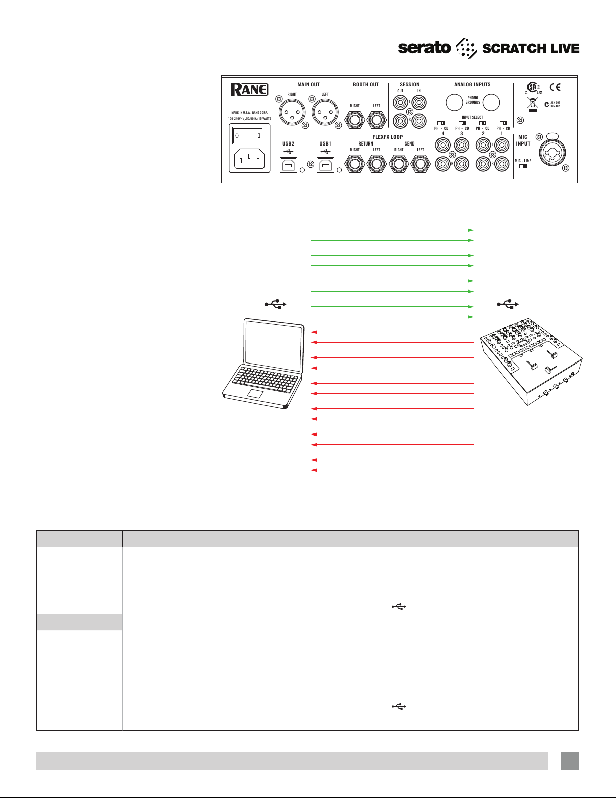
USB Audio
There are six stereo record channels and
four stereo playback channels. These
channels are simultaneously available on
two USB ports, allowing two computers to
share the device. This allows two DJs to
play together and supports uninterrupted
transitions from one DJ to another.
The Sixty-Two is a dual personality
device. When using Serato Scratch Live,
proprietary Serato Audio Research drivers
are used in place of ASIO (windows) and
Core Audio (Mac) drivers supplied by
Rane. These Rane drivers are used when
Scratch Live is not running.
Rane ASIO and Core Audio drivers
allow the Sixty-Two to act as a 12-record
8-playback USB sound card for use with
multiple third-party software applications
that support ASIO or Core Audio. ASIO
and Core Audio drivers are multi-client,
meaning they allow multiple applications
on a computer to share the device at the
same time. ASIO and Core Audio drivers
are not available when Scratch Live is
running.
The Sixty-Two has two USB ports,
allowing simultaneous connection of
two computers. Each port is completely
independent. It is possible to run Scratch
Live using proprietary drivers on one
computer while running third party
software using ASIO or Core Audio on the
other, Mac or PC, in any combination.
SIXTY-TWO
Left Virtual Deck L&R
Right Virtual Deck L&R
USB RECORD USB PLAYBACK
PGM 1 Record L&R
PGM 2 Record L&R
Left DVS Control L&R
Right DVS Control L&R
DJ-FX Send L&R
Main Mix Record L&R
SP-6 Sample Player L&R
DJ-FX Return L&R
x2 USB PORTS
USB Playback Stereo Pair Scratch Live Description Mixer Use
1
2
3
4
1-2 Left Virtual Deck Output Select as PGM 1 Source from USB A or USB B
3-4 Right Virtual Deck Output Select as PGM 2 Source from USB A or USB B
5-6 SP-6 Output Option USB AUX Source (sum of USB A and USB B)
7-8 DJ Effects Return to the Mixer
FlexFX
Insert Return (sum of USB A and USB B)
USB Record
1
2
3
4
5
6
RAN E SIXTY-TWO MIXER FOR SERATO SCRATCH LI VE • OPER ATOR’S MANUAL 2. 5.0
1-2 Record Source PGM 1 PGM-1 Post Fader and Post Crossfader Output
3-4 Record Source PGM 2 PGM-2 Post Fader and Post Crossfader Output
5-6 Record or DVS Control for Left Deck Selects PH/CD 1 or PH/CD 2 in Control Panel
7-8 Record or DVS Control for Right Deck Selects PH/CD 3 or PH/CD 4 in Control Panel
9-10 DJ Effects Send from the Mixer
FlexFX
Insert Send
11-12 Record the Main Mix or Mic Select Main Mix or Mic in the Control Panel
7
Page 8
Mixer Controls
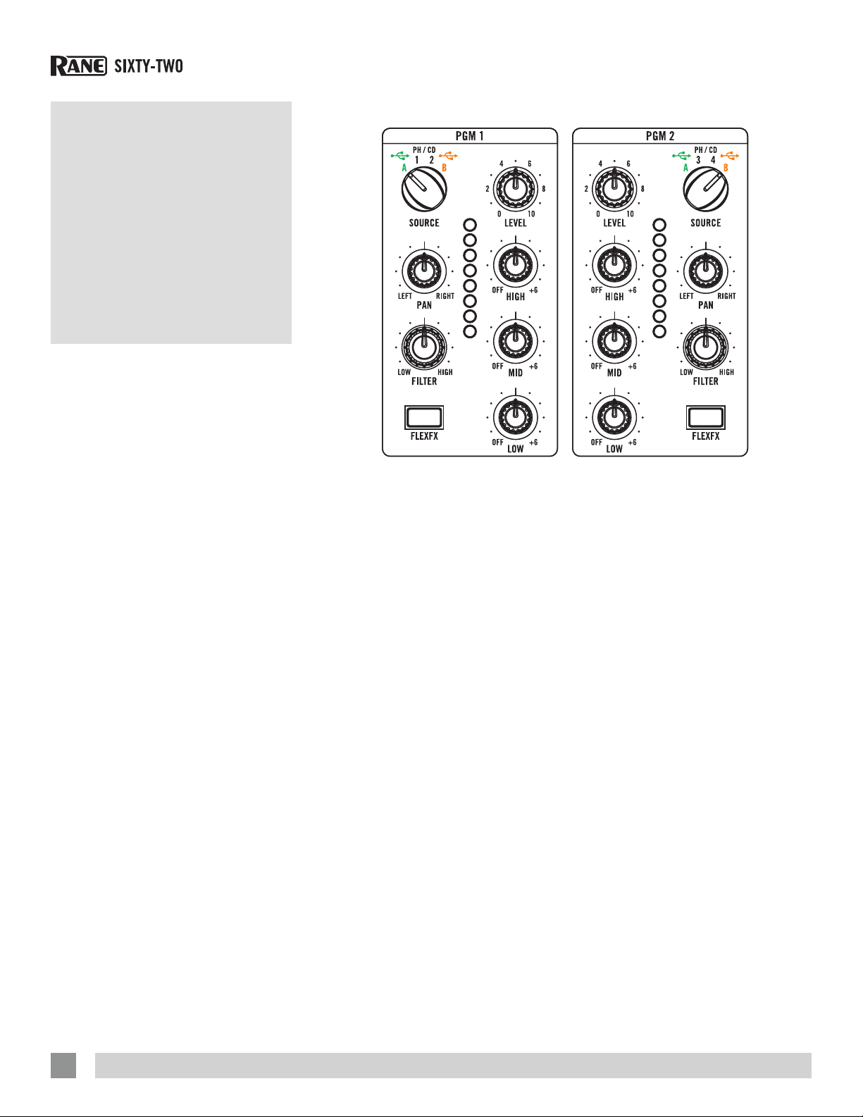
Program Channels
Two Program channels, or buses,
have nearly identical controls with the
exception of the Source selectors.
Source Selector
The SOURCE selector for PGM 1 selects
one of four sources:
• Left Virtual Deck (USB stereo playback
pair 1-2) from USB A.
• Also assigns the MIDI controls for the
Left-Deck software and PGM 1 mixer to
USB A.
• PH / CD 1 (THRU): Set to PH or CD with
the rear panel switch.
• When selected in software, this input
is available on USB record 5-6 for use
as the DVS control signal or for audio
recording. To select this control source
in Serato Scratch Live: go to Setup >
Hardware > Control Source > PGM 1
and select “1”. See “Control Source”
on page 42.
• PH / CD 2 (THRU): Set to PH or CD with
the rear panel switch.
• When selected in software, this input
is available on USB record 5-6 for use
as the DVS control signal or for audio
recording. To select this as the control
source in Serato Scratch Live: go to
Setup > Hardware > Control Source >
PGM 1 and select “2”.
• Left Virtual Deck (USB stereo playback
pair 1-2) from USB B.
• Also assigns the MIDI controls for the
Left-Deck software and PGM 1 mixer to
USB B.
The SOURCE selector for PGM 2 selects
one of four sources:
• Right Virtual Deck (USB stereo playback
pair 3-4) from USB A.
• Also assigns the MIDI controls for the
Right-Deck software and PGM 2 mixer
to USB A.
• PH / CD 3 (THRU): Set to PH or CD with
the rear panel switch.
• When selected in software, this input
is available on USB record 7-8 for use
as the DVS control signal or for audio
recording. To select this control source
in Serato Scratch Live: go to Setup >
Hardware > Control Source > PGM 2
and select “3”.
• PH / CD 4 (THRU): Set to PH or CD with
the rear panel switch.
• When selected in software, this input
is available on USB record 7-8 for use
as the DVS control signal or for audio
recording. To select this control source
in Serato Scratch Live: go to Setup >
Hardware > Control Source > PGM 2
and select “4”.
• Right Virtual Deck (USB stereo playback
pair 3-4) from USB B.
• Also assigns the MIDI controls for the
Left-Deck software and PGM 2 mixer to
USB B.
Level
LEVEL controls adjust the input gain from
off to +15 dB. Unity gain (no boost or cut)
is at 12 o’clock.
Pan
Left / Right PAN controls adjust the balance
of left and right signals. Left and right are
equal at 12 o’clock .
Tone Controls
HIGH, MID and LOW full-cut tone controls
adjust the frequency response from off to
+6 dB. Unity gain (no boost or cut) is at 12
o’clock.
Filter
The FILTER sweeps from Low-Pass to
High-Pass. Set to 12 o’clock for a at
frequency response. Moving the lter
toward the LOW position progressively
reduces high-frequencies. Moving the
lter toward the HIGH position progressively
reduces low-frequencies. The Resonance
or Q of the Filter can be adjusted in
Scratch Live: go to Setup > Hardware
> to set the Resonance. High resonance
adds a “zip” effect to the Filter when it is
moved. Low resonance is best when the
Filter is used for mixing.
8
RAN E SIXTY-TWO MIXER FOR SERATO SCRATCH LI VE • OPER ATOR’S MANUAL 2. 5.0
Page 9
FlexFX
The FLExFx button assigns a PGM channel
to the FlexFX bus where internal, external
analog or software effects via USB may be
inserted. Enable Serato Scratch Live DJ
Effects by going to Setup > Plugins > DJFX and click “Enable mixer DJ-FX send.”
The FlexFX loop allows any combination
of PGM 1, PGM 2, MIC or USB AUX to be
assigned with the option to insert internal
effects, external analog effects or software
effects via USB.
Headphone Cue
Headphone CUE assigns a signal to
the headphone monitor. Headphone
CUE controls operate as solo or radiobutton controls. This means engaging
a headphone CUE turns all the other
headphone CUE controls off. You can
select more than one at a time by
simultaneously pressing more than one
CUE.
Channel Faders & Crossfader
These faders use magnetic non-contact
mechanisms with no noise and no bleed.
Each fader has REVERSE and CONTOUR
controls on the front panel.
Channel Meters
Each PGM channel has a mono meter to
assist in setting levels. These meters are
quasi-peak with peak hold. The goal is to
stay out of the red.
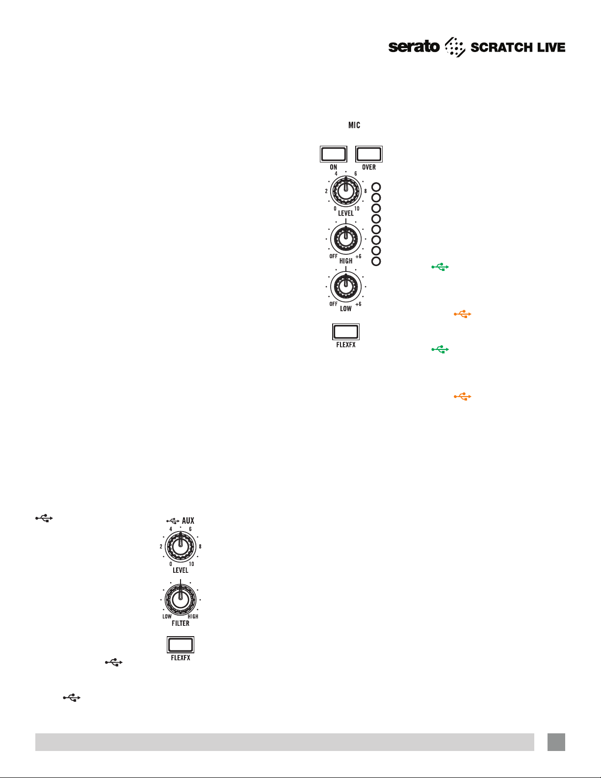
AUX
This digital input is on USB
playback stereo pair 5-6
and is normally used for the
Serato Scratch Live SP-6
sample player.
To enable the SP-6 player,
go to Setup > Plugins >
SP-6 Sample Player and
click “enable SP-6 Sample
Player Plugin.”
To assign the SP-6
Sample Player to
click the SP-6 tab on the main software
screen and select “A” as the SP-6 output.
This
AUx input has it’s own LEVEL,
AUx,
FILTER and FLExFx assign. CUE for USB AUx is
in the center just below the SAMPLES row of
buttons.
Mic Input
This Mic input on a
XLR/TRS combo jack
has LEVEL, HIGH and LOW
tone controls, FLExFx
assign and a meter.
Select MIC or LINE level
using the rear panel
switch. LINE is usually
correct for wireless mic
receivers.
MIC ON turns the
mic input on without
ducking other inputs.
MIC OVER momentarily
turns the microphone
on, and ducks other
inputs by 10 dB (about
1/3).
Session In and Out
This SESSION IN has it’s own level control
and may be used as a general purpose
analog AUX input from RCA jacks. SESSION
IN and SESSION OUT are typically used to
chain mixers together.
Main and Booth
The Main and Booth outputs each have
their own Level control. The Main outputs
use balanced XLR connectors and the
Booth outputs use balanced ¼˝ TRS
connectors. Since the Main, Booth and
Session Outputs have the same mix, you
can run any of them to your main amplier
if the proper cables are not available.
The main mix has a quasi-peak stereo
meter with peak hold.
Headphones
The Headphone Monitor provides stereo
or mono split-cue operation.
• In Stereo operation, the PAN control
pans between stereo Cue and stereo
Main Mix.
• In SPLIT CUE operation, the PAN control
pans between Mono Cue in the left ear
and mono Main Mix in the right ear.
• Individual Cue buttons are provided for
PGM 1, PGM 2, USB AUX and FlexFX
Loop.
• The Headphone Level control sets the
level in the front panel 3.5 mm and ¼˝
output jacks.
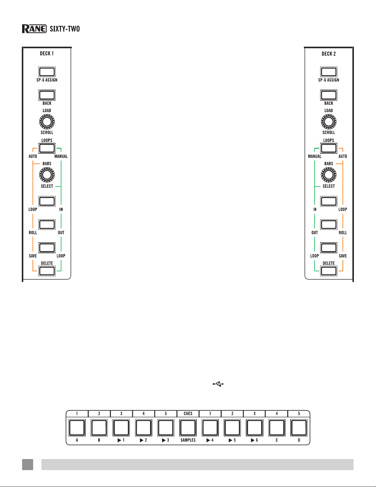
Control Strip Controls
The Sixty-Two Mixer has dedicated
Scratch Live software controls for the Left
Virtual Deck and Right Virtual Deck. The
mixer has two high-speed USB ports,
USB A and USB B. Virtual Deck and
associated PGM controls are assigned
to USB A or USB B using the PGM Input
Source selectors.
When
the SP-6 ASSIGN button at the top of the
left-hand control strip turns GREEN to
coincide with the silk-screen color for
USB A. When
ASSIGN button turns ORANGE to coincide
with the color for USB B.
When
the SP-6 ASSIGN button at the top of the
right-hand control strip turns GREEN
to coincide with the silk-screen color for
USB A. When
ASSIGN button turns ORANGE to coincide
with the color for USB B.
The MIDI controls are only sent to
the selected port, allowing completely
independent Library Browsing, Cue, Loop
and Sample control for each USB port.
MIDI controls not dedicated to a channel
strip, such as SP-6 player controls, are
assigned to the Left or Right control-strip
using the SP-6 ASSIGN control.
Library Browse
BACK button: Switches the focus between
the Crate and Library area in Scratch Live.
If you have any panels open in Serato
Scratch Live, the BACK button will also
move the focus between this and the
Crate and Library areas.
SCROLL / LOAD encoder: Rotate the knob to
scroll through the Crate / Library panel
currently in focus. When the focus is in the
Crate area, pressing the knob displays the
contents of the selected Crate and moves
the focus into the Library area. When
the focus is in the Library area, pressing
A is selected for PGM 1,
B is selected, the SP-6
A is selected for PGM 2,
B is selected, the SP-6
RAN E SIXTY-TWO MIXER FOR SERATO SCRATCH LI VE • OPER ATOR’S MANUAL 2. 5.0
9
Page 10
the knob loads the selected track to the
Virtual Deck. Double-pressing will load
an instant double to this Deck from the
opposite Deck.
Loops Manual / Auto
MANUAL / AUTO button toggles the state of
the Loop controls between Manual and
Auto Loop mode. In Manual mode, the
LOOP buttons light GREEN to correspond
with the GREEN lines by the LOOP controls.
In Auto mode, the buttons are lit ORANGE
to correspond with the ORANGE lines.
In CUE mode, the CUES / SAMPLES
button is ORANGE and the Cue buttons
are GREEN. There are ve Cue buttons
dedicated to the Left Virtual Deck and
ve dedicated to the Right Virtual Deck,
numbered above each button.
In SAMPLES mode, the CUES / SAMPLES
button is RED, the four Bank buttons
A, B, C and D are ORANGE and the six
Sample buttons are GREEN. Sample
buttons are assigned to USB A or USB
B using the SP-6 ASSIGN button at the top
of each control strip. See “Control Strip
Controls” on page 9.
Manual Loop Controls
When Manual Loop mode is selected, loop
control buttons are illuminated GREEN.
Loop buttons ash during loop playback.
SELECT - Selects a loop slot in Scratch Live
when the encoder is pressed.
IN - Sets a loop in point.
OUT - Sets a loop out point.
LOOP - Turns a loop on or off.
DELETE - Allows you to delete a loop. Press
Delete and the Loop button now glows
ORANGE. Next, use the SELECT knob to
select the loop to be deleted then press
the ashing LOOP button.
Auto Loop Controls
When Auto loop mode is selected, loop
control buttons are illuminated ORANGE.
BARS - Selects the auto loop length in
Scratch Live. This can be adjusted while
an auto loop is already looping as an
effect.
LOOP - Performs an auto loop of the
number of Bars selected.
ROLL - Performs a loop roll of the number
of Bars selected.
SAVE - Saves the current loop to an
available loop slot in Scratch Live.
Cues / Samples control
The CUES / SAMPLES button toggles the ten
CUE buttons between CUES and SAMPLES
modes.
Cue Points
In CUE mode, you can set and trigger
ve cue points for each Virtual Deck
using the Cue buttons. If a Cue is set in
Scratch Live, a Cue button is lit bright
GREEN, and pressing it will trigger the
corresponding Cue point in Scratch
Live. If a corresponding Cue point is not
set, the button will be dim GREEN and
pressing it will set a new cue point. You
can delete a Cue point in Scratch Live by
pressing and holding the DELETE button
in the active control strip, then pressing
the corresponding Cue button. see “Cue
Points” on page 26.
Sample Player (SP-6) Triggers
In SAMPLES mode, you can trigger six
samples in each of four banks. Select
Bank A, B, C or D. An ORANGE Bank
button is brightly lit if any of the six slots
in that bank have a track loaded, and that
Bank is currently selected. When a bank
is selected, any GREEN Sample button
with a track loaded in the corresponding
slot is brightly lit. The button ashes while
its sample is playing. The Play behavior
follows the behavior selected in Scratch
Live. Sample playback can be assigned
to the Left Virtual Deck, Right Virtual
Deck or
dedicated USB AUX input for the sample
player typically used for SP-6 playback.
AUX. The Sixty-Two has a
10
RAN E SIXTY-TWO MIXER FOR SERATO SCRATCH LI VE • OPER ATOR’S MANUAL 2. 5.0
Page 11
When two USB ports are in use, the SP-6
SEND
LEFT
RIGHT
RETURN
LEFT
RIGHT
USB
Record
USB
Playback
Main
Mix
Cue
Bus
CUE
ASSIGN button at the top of each control
strip determines which computer the SP-6
player controls are assigned to. Audio
from both USB ports is summed in the
mixer. See “SP-6 Sample Player” on
page 28.
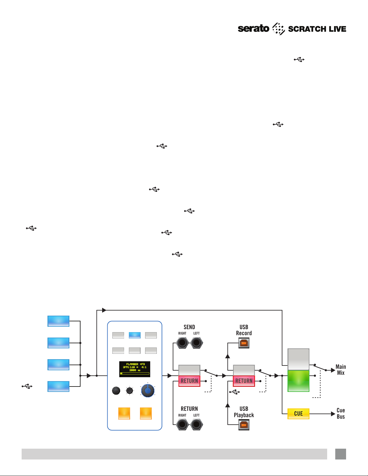
FlexFX
The FlexFX Bus in the Sixty-Two works
differently than a typical effects insert
loop. This architecture is very exible
and opens up many new possibilities not
possible with simple effect insert designs
found on other mixers.
The FlexFX Bus is more like an auxiliary
bus that can have multiple signals
assigned to it. Signals assigned to the bus
may then have internal effects, external
analog effects and external USB effects
applied in any combination. The order of
processing in the FlexFX Bus is shown in
the graphic below.
1. FLExFx buttons for PGM 1, PGM 2, MIC and
AUx assign signals to the FlexFX
Bus (BRIGHT BLUE) or the Main Mix
(DIM BLUE). This allows assigning
multiple inputs to the FlexFX Bus and/
or changing the assignment without
interrupting audio.
2. The six effect buttons both turn on and
sync an internal effect. By keeping this
separate from the effects ON button,
it is possible to turn on, sync and cue
effects before you hear the Wet signal
in the Main Mix. Only one internal
effect is selected at a time. Having six
independent buttons, it is possible
to drum in different effects without
interruption.
3. ExT. INSERT is turned on/off with a
separate button. The external analog
insert can be used with internal effects
and the
INSERT or independently.
NOTE: If no external connection is
made to the FLExFx LOOP RETURN jack, the
signal will be interrupted when the ExT.
INSERT button is turned on.
4. The
INSERT is turned on/off with
a separate button, and can be used
with internal effects, the ExT. INSERT or
independently. The
INSERT uses
USB record pair 9-10 for the Send and
USB playback pair 7-8 for the Return.
Using the
INSERT generally requires
a low latency setting. NOTE: Assign a
PGM channel or signal to FLExFx before
engaging the
INSERT button to
avoid audible artifacts.
In the setup screen, both DJ-FX and
Enable Mixer DJ-FX Send must be
checked to use the
INSERT button.
See “Enable DJ-FX” on page 45,
and “Enable Mixer DJ-FX Send” on
page 45.
NOTE: If no connection is made in
Scratch Live between the USB send
and USB return or “Enable Mixer DJFX send” is not checked in Scratch
Live, the signal will be interrupted
when the
INSERT button is turned
on.
5. The FlexFX CUE is after the internal
effects insert, analog external insert,
USB insert and before the effects ON
function. This allows cueing a Wet signal
while listening to the Dry signal before
turning the effect ON.
6. When effect ON is not engaged, internal
effects insert, analog external insert and
USB insert points are bypassed, and
any signal assigned to the FlexFX Loop
is simply summed into the main mix.
This allows you to CUE the Wet signal
before the Wet signal is heard in the
Main Mix.
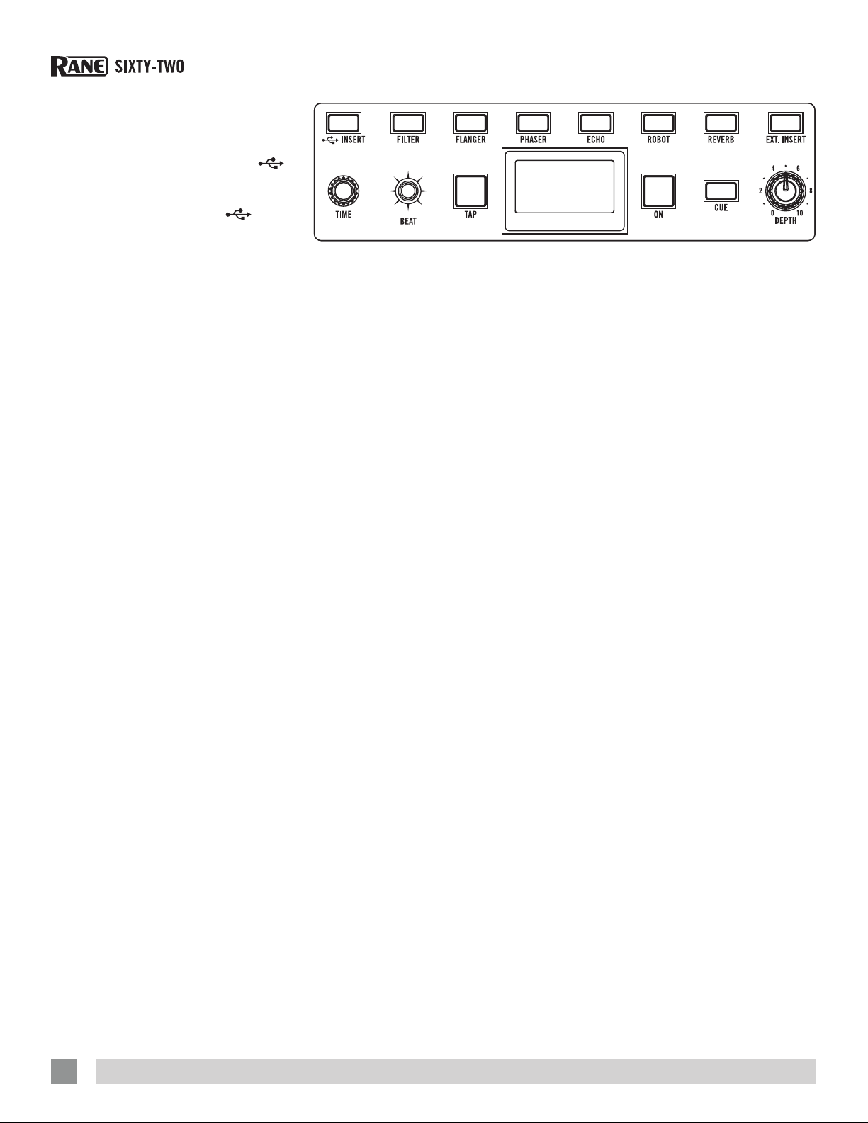
1 2 3 4
FLEXFXPGM 1
EFFECTS ENGINE
FLEXFXPGM 2
FLEXFXMIC
FILTER
BPM:120 * 4:1
FLANGER +FB
FLEXFXAUX
TIME BEAT
TAP
RAN E SIXTY-TWO MIXER FOR SERATO SCRATCH LI VE • OPER ATOR’S MANUAL 2. 5.0
PHASERFLANGER
ROBOTECHO REVERB
2000 MS
2
0
DEPTH
ON
SEND
64
8
10
RETURN
EXT. INSERT
SEND
RETURN
INSERT
6
BYPASS
ON
FLEXFX ON
5
11
Page 12
Internal Audio Effects
The internal effects engine is located
in the FlexFX Loop. This allows any
combination of PGM 1, PGM 2, MIC and
AUx to be assigned to an effect. Individual
effects are turned on/off using the six
effects buttons. ExT. INSERT and
are also engaged independently. The
FlexFX Loop (which includes the External
Insert and the USB Insert) is turned On/Off
with the FlexFX ON button (off bypasses
the loop).
The six built-in effects are:
• FILTER • FLANGER • PHASER
• HOLD ECHO • ROBOT • REVERB
General Behavior
• The effect multiplier is saved for each
effect.
• Changing BPM for one effect changes
the BPM for all effects.
• Tapping the BPM requires at least two
taps.
• Changing the Beat multiplier results in
an immediate change in the effect time.
• Changing the effect BPM adjusts the
multiplier for other effects so that the
new multiplier is as close as possible to
the saved effect time.
Effects Display, BPM Source and Match
Indicator
The effects display shows the name of
the current effect, BPM, MIDI Beat-Clock
source, Beat Multiplier and Time. A bar
graph represents the effect time relative
to its range. If no effect is selected, the
information for the last effect is displayed.
The display for the Robot and Reverb is
somewhat different as outlined below.
There four possible BPM sources:
(*) Manual Tap
(S) Scratch Live
(A) USB A Beat-Clock,
(B) USB B Beat-Clock.
To change the BPM source, press
and hold the TAP button and use the BEAT
joystick to step through the sources. If
a new BPM is manually tapped in or the
time is manually altered, the BPM source
returns to (*) Manual.
INSERT
The effect time is normally a product
of the BPM and the Beat Multiplier. If the
right arrow or left arrow appears, there
is an inequality between the BPM*Beat
and Time. The arrow indicates which way
to adjust the Beat Multiplier to correct the
inequality and get the closest possible
time. If the BPM source is displayed
(*, S, A, B), the BPM*Beat matches the
displayed Time.
For example, 120 BPM with a 4:1 Beat
Multiplier would result in an effect Time
of 2000 ms. If the Time is adjusted to a
different value, such as 2097 ms, an arrow
indicates that the product of the displayed
BPM and Beat Multiplier does not result
in the displayed effect Time. For this
example, 2000 ms is below 2097 ms. In
this case, moving the BEAT joystick left or
down snaps to 120 * 4:1 and changes the
time to 2000 ms.
A ashing Beat Multiplier indicates that
the Time required to match the current
BPM*Beat product is out of range. For
an echo example, if a BPM of 60 is used
with a Beat Multiplier of 8, the resulting
time is 8000 milliseconds. If the multiplier
is set to 16, the resulting time would be
16000 milliseconds, which is out of range.
In this case, the time remains at 8000
milliseconds and the multiplier ashes.
Effects Synchronization
This mixer can synchronize its internal
effects to four sources as described in
the preceding section. The desired clock
source is selected by holding down the
TAP button and pushing the BEAT joystick
up/right or down/left. The selected source
(*, S, A, B) is displayed just following the
BPM number. Manually tapping a BPM
forces the selection to (*) Manual.
Pressing a FLExFx button with no other
FLExFx button engaged, with a BPMtagged song playing in Scratch Live on
that channel, forces the clock source to
(S) Scratch Live. The mixer will continue
to track the Scratch Live BPM until a new
BPM is manually tapped or a new clock
source is selected. When one of S, A, or B
is selected, the clock source indicator will
ash when the mixer is actively following
the selected clock.
At any point the BPM and BPM source
can be locked. By clicking down on the
Joystick, the current BPM is frozen and
the BPM source is set to (*) Manual and
locked. The BPM label on the display
ashes to indicate that the BPM source
has been locked. The mixer will not
change the BPM or BPM source until the
user manually enters new BPM or time
information, changes the BPM source, or
unlocks the BPM by clicking down once
more on the Joystick.
Regardless of the clock source, the
mixer broadcasts the current MIDI BeatClock to both USB ports when the Send
MIDI Beat Clock option is selected in the
MIDI Conguration page of the driver
control panel. Both USB ports will also
echo out any system real-time messages
from the host computer. See “Core Audio
and ASIO Drivers” on page 14.
12
RAN E SIXTY-TWO MIXER FOR SERATO SCRATCH LI VE • OPER ATOR’S MANUAL 2. 5.0
Page 13
Effects Parameter Table
Effect Depth Knob Time Encoder Tap Button Beat Joystick Control Panel Option*
Adjusts the BPM
multiplier to change the
Filter
Adjusts the strength of
the effect.
Flanger
Phaser None
Adjusts the amount
of echo recirculation,
which in turn affects
how quickly the echo
effect decays. The
amount of recirculation
varies with the echo
options selected (see
last column). Setting
the control to minimum
or “0” results in a
Echo
Robot
Reverb Adjusts reverb intensity.
Dry signal with the
minimum recirculation
setting. Setting the
control to maximum
or “10” results a Wet
signal with maximum
recirculation.
When either Hold Echo option is selected, it is possible to suspend an echo. To engage suspend, press the
TIME encoder. The ECHO button ashes, indicating that suspend is active. Suspend terminates input to the
delay memory while continuing to play delay memory indenitely. Press the TIME encoder again to terminate
suspend. If you want a suspended echo to gradually decay, turn the DEPTH knob CCW. If you want the decay
to stop, turn the DEPTH knob back to or above where it was at when suspend was engaged.
Adjusts the Wet/Dry
mix and warble of the
robot.
Adjusts the LFO time
independent of the current
BPM and Beat Multiplier.
• Holding down the TAP
button and turning the
TIME encoder adjusts the
BPM.
• Pressing the TIME encoder
re-syncs the effect.
Adjusts the length of the
recorded sample used by
the echo.
• Holding down the TAP
button and turning the
TIME encoder adjusts the
BPM.
• Pressing the ECHO button
clears the echo. Time
range is 1 ms to 10920
ms.
Hold down the ECHO button
and turn the TIME encoder
to adjust the ltered echo
frequency.
Adjusts the % of pitch shift.
• % of pitch shift is shown
by the bar in the display.
• Pressing the TIME encoder
resets pitch shift to 0%.
Adjusts reverb decay time.
• % of decay time is
shown by the bar in the
display.
The TAP button
manually enters a new
BPM.
• A minimum of two
taps is required to
get a new BPM.
• Manually tapping
in a BPM switches
the BPM source to
(*) Manual.
Pressing the TAP
button and tilting the
BEAT joystick up/right
or down/left selects
the BPM source.
The source is shown
in the mixer display
after the BPM
number:
(*) Manual Tap
(S) Scratch Live
(A) USB A Beat-Clock,
(B) USB B Beat-Clock.
Does not affect the
robot.
Does not affect
reverb.
number of bars.
• UP increases the
multiplier and DOWN
decreases the multiplier.
• Available multiplier
values are: 1/16, 1/8,
1/4, 1/2, 3/4, 1/1, 2/1
4/1, 8/1, 16/1, 32/1 and
64/1. (64/1 not available
in Echo).
Press down on the
BEAT joystick to Lock
the current BPM. This
prevents the current BPM
from changing until you
manually change the
BPM, Time, BPM Clock
Source, or click the Beat
Joystick Button again to
unlock it. Locked BPM
is indicated by “BPM”
ashing in the display.
Hold down the FILTER
button and toggle the BEAT
joystick to scroll through
the Filter types.
Hold down the FLANGER
button and toggle the BEAT
joystick to switch between
+ / – feedback.
Hold down the ECHO
button and toggle the BEAT
joystick to scroll through
the Echo types.
Adjusts the pitch up/right
or down/left in 20% steps.
Adjusts the decay time
up/right or down/left in
10% steps.
• High-Pass Filter with
low or high frequency
sync.
• Low-Pass Filter with
low or high frequency
sync.
• Flanger with positive
feedback.
• Flanger with negative
feedback.
• Echo: No feedback
lter. Recirculation is
adjustable 0-70%.
• Hold Echo: No
feedback lter.
Recirculation is
adjustable 0-100%.
• Low-Cut Echo:
Feedback lter
adjustable from
20 Hz to 10 kHz.
Recirculation is
adjustable 0-70%.
• Low-Cut Hold Echo:
Feedback lter
adjustable from
20 Hz to 10 kHz.
Recirculation is
adjustable 0-100%.
None
*Effect options available
in the Scratch Live,
ASIO and Core Audio
hardware control panels.
RAN E SIXTY-TWO MIXER FOR SERATO SCRATCH LI VE • OPER ATOR’S MANUAL 2. 5.0
13
Page 14
Core Audio and ASIO Drivers
The Scratch Live installer includes drivers
that allow you to use your Rane Sixty-Two
with other audio applications. The Core
Audio (Mac) and ASIO (PC) drivers can be
installed when you install Scratch Live.
See the instructions in “Installing Scratch
Live” on page 12.
Once installed, you will have the option
to use the Sixty-Two with 3rd party DAWs
using ASIO or Core Audio interfaces.
NOTE: These drivers only work with audio
applications that are compatible with
these audio standards.
ASIO (Windows)
The Sixty-Two comes with a low-latency
ASIO device driver to interface with
software applications other than Scratch
Live on Windows operating systems.
Multi-client ASIO allows different audio
software applications to simultaneously
stream audio to and from the Sixty-Two.
If the same playback channel is selected
in more than one application, the driver
mixes the audio from the applications
before streaming it to the device.
The driver Control Panel may be
launched from the Windows Control
Panel. Select Start > Control Panel > Rane
Sixty-Two.
Core Audio (Macintosh)
The Sixty-Two uses a low-latency Core
Audio device driver to interface with
software applications other than Scratch
Live on Macintosh operating systems.
Core Audio allows different audio software
applications to simultaneously stream
audio to and from the Sixty-Two.
To launch the Sixty-Two driver Control
Panel, open the System Preferences
window. Locate the Sixty-Two in the
“Other” section and click the Sixty-Two
icon.
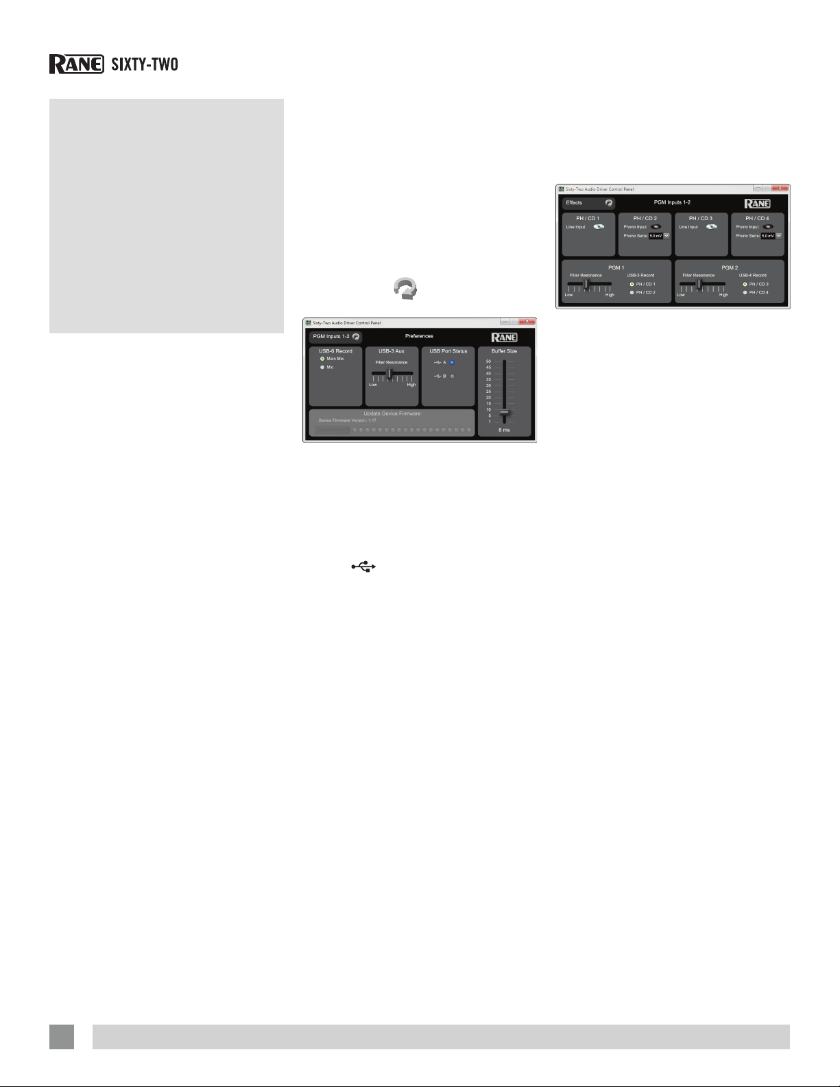
Driver Control Panel
The control Panel consists of four pages:
Preferences, Program Inputs 1-2, Effects
and MIDI. To move between the four
pages, click the
left-hand corner of the control panel.
Preferences page controls:
• USB-6 (11-12) Record source: Two
radio buttons select the Main Mix or
Mic.
• USB-3 (5-6) Filter Resonance: Slider
adjusts the resonance from Low to High
for the
• USB Port Status: Indicates active USB
port(s).
• Buffer Size: The Buffer Size control
allows the USB driver buffer to be
increased or decreased. The Sixty-Two
drivers are designed to run at latencies
as low 8 milliseconds. However,
computer performance and available
resources (number of applications
running) may adversely affect the
computer’s ability to stream audio
reliably. If pops and clicks are heard in
the USB audio, try increasing the buffer
size to eliminate them. With ASIO, total
round-trip latency is equal to Buffer Size
plus device latency. With Core Audio,
total round-trip latency is equal to Buffer
Size plus software application buffer
latency, plus device latency. Device
latency is 2.26 ms.
• Update Device Firmware: This panel
indicates the rmware version currently
installed in the Sixty-Two. If the SixtyTwo rmware installed on your computer
is newer than the rmware in your
AUx Filter.
icon in the upper
Sixty-Two, the Update Device Firmware
panel is enabled. Pressing the Update
Firmware button updates the Sixty-Two
rmware to the newer version.
PGM Inputs 1-2 Page Controls:
There is one panel for each channel strip
on the mixer. Each PGM panel controls
these functions:
• Analog Input Source: The analog input
for each channel may be set for Line
level (CD) or Phono level (PH) using a
switch on the rear of the mixer. PH/CD 1
and PH/CD 2 are associated with PGM
1. PH/CD 3 and PH/CD 4 are associated
with PGM 2. The control panel shows
the input mode selected on the mixer for
each of the four inputs. The mode can
only be changed on the mixer.
• Phono Sensitivity: If Phono Input
is selected on the mixer, the Phono
Sensitivity adjustment appears in the
panel. Click the down-arrow to display
a list of 16 sensitivity settings between
2.5 mV and 10 mV in 0.5 mV steps. The
default is 5 mV. Set the Phono Sensitivity
to the same level of your cartridge
(see your cartridge documentation for
the correct value). Another method is
to match the level of a CD on another
input.
• Filter Resonance: Each channel of
the Sixty-Two has a Filter knob that
provides High- and Low-Pass ltering.
Filter resonance controls the “peak”
of the lter cutoff frequency. The Low
setting provides the smoothest Filter
without adding gain. The High setting
adds accent to frequencies near the
Filter cutoff point by adding about 12 dB
of gain. Adding gain in a narrow region
around the cutoff frequency adds a “zip”
effect to audio as the Filter is swept. The
default is 5 dB.
14
RAN E SIXTY-TWO MIXER FOR SERATO SCRATCH LI VE • OPER ATOR’S MANUAL 2. 5.0
Page 15
• USB-3 (5-6) Record Source: This
control allows users to select one of two
analog sources as the vinyl emulation or
USB record source for PGM 1. The two
radio buttons allow the user to select
PH/CD 1 or PH/CD 2. The post PGM
1 fader signal is always available for
recording on USB 1 (1-2) record.
• USB-4 (7-8) Record Source: This
control allows selecting one of two
analog sources as the vinyl emulation
or the USB record source for PGM 2.
The two radio buttons allow the user to
select PH/CD 3 or PH/CD 4. The post
PGM 2 fader signal is always available
for recording on USB 2 (3-4) record.
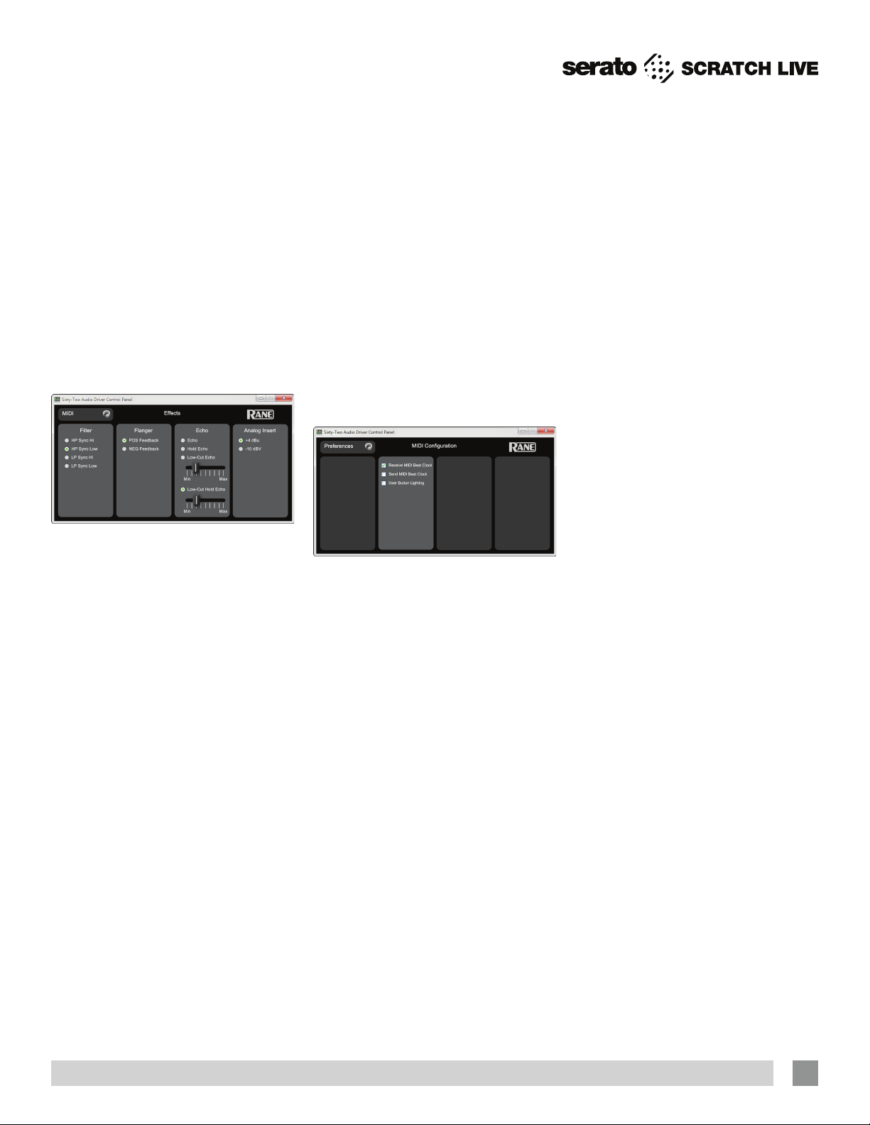
Effects Page Controls:
The Filter panel has four radio buttons
allowing users to select lter type and
sync mode:
• High-Pass Filter with high-frequency
sync.
• High-Pass Filter with low-frequency
sync.
• Low-Pass Filter with high-frequency
sync.
• Low-Pass Filter with low-frequency
sync.
The Flanger panel has two radio buttons
allowing users to select one of two
feedback modes:
• Positive feedback.
• Negative feedback.
The Echo panel allows users to select
one of four echo modes:
• Echo with no feedback lter and
adjustable recirculation 0 to 70%.
• Hold Echo with no feedback lter
and adjustable recirculation of 0% to
100%.
• Low-Cut Echo with adjustable
feedback lter and adjustable
recirculation 0 to 70%.
• Low-Cut Hold Echo with adjustable
feedback lter and adjustable
recirculation of 0% to 100%.
• The sliders in the control panel set
the low-cut lter cut off frequency.
Echo Default Effects settings are:
• Low-Pass Filter with high-frequency
sync.
• Flanger with positive feedback.
• Echo with no feedback lter.
• Echo lter frequencies default to 82
Hz.
The Analog Insert panel has two options:
• +4 dBu
• -10 dBV
We recommend the +4 dBu setting unless
you insert a low-voltage device, in which
you should use the -10 dBV setting.
MIDI Configuration Page:
• When Receive MIDI Beat Clock is
checked, the mixer receives MIDI Real
Time System Messages.
• When Send MIDI Beat Clock is
checked, the mixer sends MIDI Real
Time System Messages.
• When User Button Lighting is checked,
the mixer will not automatically light
button LEDs for momentary presses.
Enable this option if you wish to send
MIDI commands to the mixer from thirdparty software to control button LEDs.
Factory Defaults
To reset the Sixty-Two Mixer’s:
• Record/Control Sources
• LP/HP Filter Resonances
• Filter Type, Flanger and Echo effects
to factory default settings:
1. Power off the Sixty-Two.
2. Push both PGM 1 and 2 FLExFx buttons
at the same time.
4. While holding these buttons down,
power on the Sixty-Two.
5. Immediately after fading up, the FLExFx
lights ash one time, indicating a
successful reset.
NOTE: Settings are saved in the mixer.
Software is updated with the mixer’s
settings. Therefore, the mixer may
replace control source and effect
settings in Scratch Live or software
control panels with current mixer
settings that may have been changed
by a different laptop.
RAN E SIXTY-TWO MIXER FOR SERATO SCRATCH LI VE • OPER ATOR’S MANUAL 2. 5.0
15
Page 16
the left and right channels swapped from
your deck.
Scratch Live: Getting Started
System Overview
The Scratch Live control records and
CDs are pressed with an audible tone
specically developed for controlling the
Scratch Live software application.
The Sixty-Two converts the control
signal coming from each deck into digital
audio, to be sent via USB to the Scratch
Live software, which decodes that signal
into a stream of information based on
what the DJ is doing with the control disc.
A virtual ‘deck’ replicates the movements
of the control disc. Audio les loaded
onto the Virtual Decks are then played
back through the outputs of the SixtyTwo, with any manipulation of the control
discs reproduced on the audio, effectively
emulating vinyl control of the les loaded
in software.
Connecting the Sixty-Two
Follow these steps to set up the SixtyTwo for Scratch Live, using up to two
turntables or CD players to control the
software playback.
1. Inputs
Connect your CD players or turntables
to the ANALOG INPUTS on the Sixty-Two.
Connect the deck left of the mixer to 1 or
2, and the deck on the right to 3 or 4.
Match the L channel from each of
your decks (usually white) with the white
(uppermost) RCA sockets on the mixer
and R (usually red) with the red sockets.
This is important to give Scratch Live
the correct direction of playback. If your
songs play backwards, you probably have
2. Input Level Selection
Set each input to the correct input level
using the PH - CD switches. PH = Phono and
CD = Line (for CD players). Unused inputs
are best set to CD.
3. USB Audio
Select Scratch Live as the audio source
for a channel by turning a PGM SOURCE
knob to a
analogue inputs may be used for Scratch
Live vinyl emulation control. Control input
sources for both PGM 1 and PGM 2 are
selected in the Scratch Live setup screen.
4. Connect the Sixty-Two to your
computer
Using the provided USB cable, connect
either USB A or USB B to an available
USB 2.0 port on your computer. Make
sure you connect it directly to your
computer and not through a hub or
splitter.
USB input. Any of the four
Turntable Setup
1. Set the tone arms to the specic
recommendations of the cartridge
used, so that the needle never leaves
the record, but not heavy enough that
it heats up signicantly. Both produce
poor tracking.
2. Grounding is extremely important when
using Scratch Live. Make sure you have
good connections from the ground wires
of your turntables to a grounding post
on the Sixty-Two. If you do not ground
your turntables properly, the control
signal will be noisy and the tracking of
the record position will be erratic.
CD Player Setup
Disable all built-in effects on the CD
player, including keylock/master tempo.
Installing Scratch Live
Check for the latest download version of
Scratch Live software at serato.com. If it
is newer than the version on your CDROM, we recommend installing it instead.
Mac
1. Insert the Software Installation CD-
ROM and double-click the Scratch Live
Installer.mpkg icon.
or
Launch the installer you just
downloaded from serato.com.
2. Follow the on-screen instructions. Once
the installation is complete, Scratch Live
will appear in your applications list. You
may like to drag the Scratch Live icon to
your dock for quick launching.
3. Plug in your Sixty-Two. No extra
installation is required to use Scratch
Live.
16
RAN E SIXTY-TWO MIXER FOR SERATO SCRATCH LI VE • OPER ATOR’S MANUAL 2. 5.0
Page 17
4. The optional Rane Device Drivers
are required for other software you
may have that uses Core Audio to
communicate with your Rane device. To
install the Core Audio drivers, doubleclick the .pkg le inside the appropriate
product folder in the Rane Device
Drivers folder on the software installation
CD. Core Audio driver updates are
available to download from the product’s
page at dj.rane.com.
Windows
It is important that Windows users install
the Sixty-Two drivers as well as the
Scratch Live software. The easiest way
to do this is to allow the Scratch Live
installer to do all the work.
1. Connect your Sixty-Two before you
insert your installation CD. When you
rst connect it, Windows will attempt
to install the drivers via the hardware
wizard. Cancel and close the hardware
wizard.
2. Insert the Software Installation CDROM. Make sure your Sixty-One is
connected rst. If a window doesn’t
open automatically, browse to the CD
drive. Run setup.exe.
or
Launch the installer you just
downloaded from serato.com.
3. Follow the on-screen instructions. Once
the installation is complete, Scratch
Live appears in the Start Menu under All
Programs > Serato > Scratch Live.
Because the Sixty-Two was connected
prior to installing Scratch Live, no extra
hardware installation is required.
Additional Windows ASIO Drivers
Once Scratch Live is installed, any
additional hardware that is connected
will be recognized and the drivers will be
automatically installed.
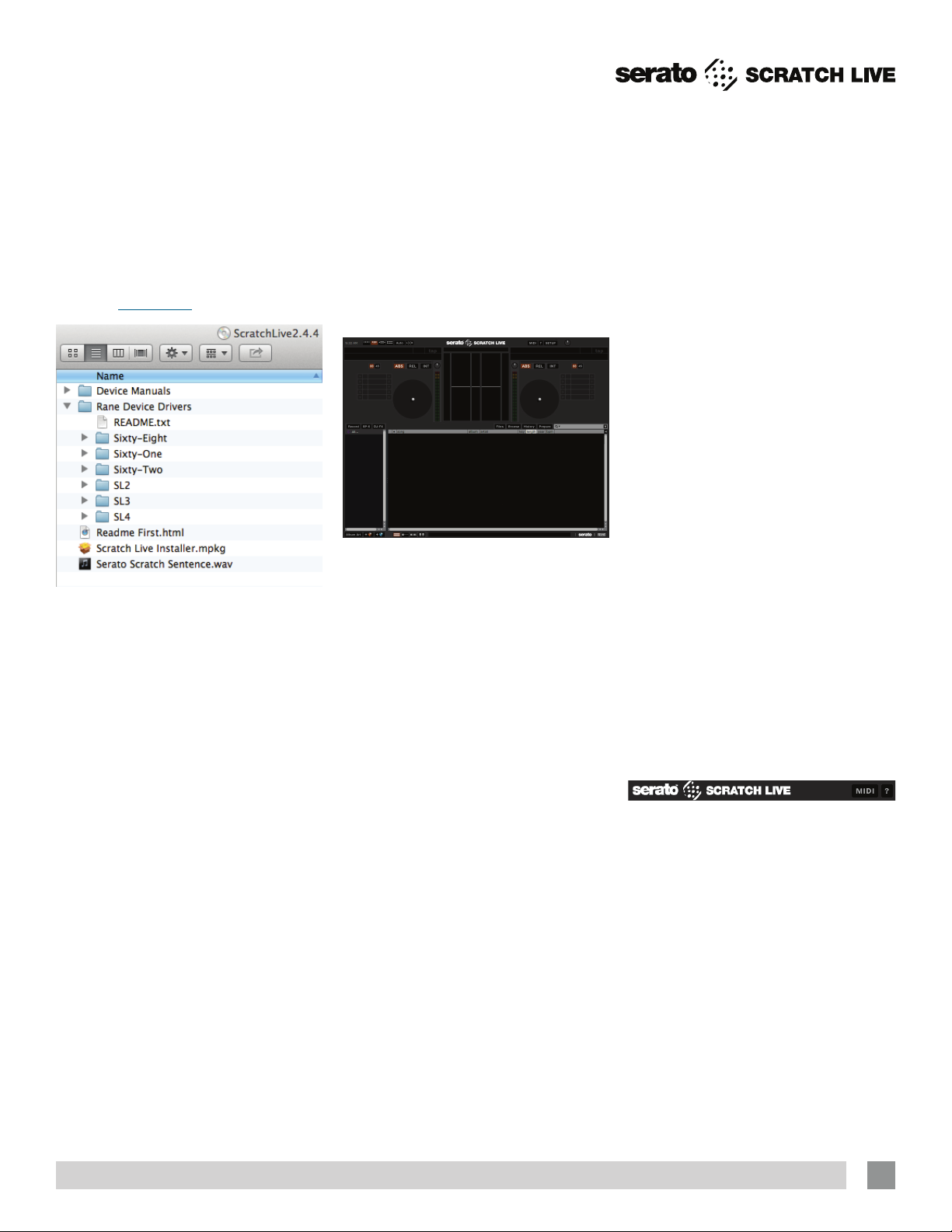
Starting the Software
Close all other programs on your Mac or
PC.
When you load Scratch Live for the rst
time, you will see the screen shown
above.
Installing More Than One Version
Installing a new version will by default
overwrite any previous version you had
installed, however it is easy to have more
than one version of Scratch Live installed
if you wish.
Mac users: before installing, nd the
Scratch Live application (by default it is
in the Applications folder), and rename
it - for example Scratch Live 2.0.0.
When you install the new version, the
old application will not be overwritten,
and you can choose which version you
want to run by going into the folder and
double clicking on the application. You
can also do this if you have already
installed the latest version - just rename
the application (eg. to Scratch Live
2.1.1), and then reinstall the earlier
version.
Windows Users: before installing, nd the
Scratch Live executable (by default it is
in C:\Program les\Serato\ScratchLIVE),
and rename it - for example Scratch
Live 2.0.0.exe. When you install the
new version, the old executable will not
be overwritten, and you can choose
which version you want to run by going
into the folder and double-clicking
the executable. You can also do this
if you have already installed the latest
version — just rename the executable
(eg. to Scratch Live 2.1.1.exe), and then
reinstall the earlier version.
Firmware Check
On occasion new rmware updates are
included within Scratch Live software
updates. After updating, run Scratch
Live and click the Hardware tab in the
Setup screen to see if new rmware is
installable. See “Updating Firmware” on
page 42.
If you’re using the TTM 57SL and/or
Sixty-Two mixers at various clubs, you
may come across one that has a newer
version of rmware installed. With the
newer rmware, the mixer will still be
usable with older Scratch Live versions,
but certain features may not work as
expected. To avoid this situation, make
sure you always have the latest version of
Scratch Live installed.
Using the Tool Tips
Click on the ? icon to enable tool tips.
Tool tips provide a handy way to learn
the various features of Scratch Live.
Move the mouse over a section of the
screen to bring up a context-sensitive
tool tip. Holding the mouse over the ?
button with tool tips turned on will show
you a list of all keyboard shortcuts. Tool
tips are available in several languages.
Scratch Live will display the tool tips in
the language that your computer is set to.
If your language is not available, the tool
tips will be displayed in English.
RAN E SIXTY-TWO MIXER FOR SERATO SCRATCH LI VE • OPER ATOR’S MANUAL 2. 5.0
17
Page 18
Calibrating Scratch Live
Since Scratch Live is controlled by an
analog signal, there is no guarantee of
what state that signal will be in by the time
the software gets to interpret it. Therefore,
Scratch Live needs to be able to handle a
wide range of signals, and be congurable
to use them optimally. Calibrating is just
conguring the software to your situation.
Calibration is equally important for both
vinyl and CD users of Scratch Live.
There are two parts to the Scratch Live
control signal: The directional tone, and
the noise map. Listening to the control
vinyl, the directional tone is the 1 kHz
tone. The noise map sounds like random
noise over the top of the tone.
The directional tone provides the
current speed and direction of the record,
while the noise map tells the software
precisely where on the record the needle
is currently.
The Noise Threshold
A threshold is a lower limit, below which
a process will not occur. In the case of
Scratch Live, the noise threshold is the
limit below which the input signal will not
be interpreted as control signal; in other
words if it’s below the threshold, it is
considered noise and ignored.
This setting is necessary because a
stylus is very sensitive, and will inevitably
pick up noise from the environment as
well as the signal on the record, especially
in the noisy environment of a live show.
How to Calibrate Scratch Live
With music playing in the background
(from any source), put your needle on
the record with the turntable stopped.
If you are using CD players, the same
rules apply. Have the CD deck paused
or stopped while calibrating. Ensure the
input level in Scratch Live is set correctly
to Line (CD). See “Input Select Status”
on page 42.
Click and hold the Estimate button
until the slider stops moving. Moving
the threshold slider to the left will make
Scratch Live more sensitive to slow record
movement, but also more sensitive to
background noise.
Repeat the process for each deck.
Things to remember:
• Your needle must be on the record.
• Your turntable (or CD player) must be
stationary.
• The background music playing must be
at a similar level to which you will play
your set at.
• Calibrate Scratch Live every time you
play.
TIP: If the slider jumps to the far right,
then you have a problem with noise
in your turntables/CD players/mixer.
Check all your connections and make
sure your equipment is well earthed.
In some situations you will not be able
to improve the signal quality, and you
will have to play on regardless. In this
situation, stick to REL mode.
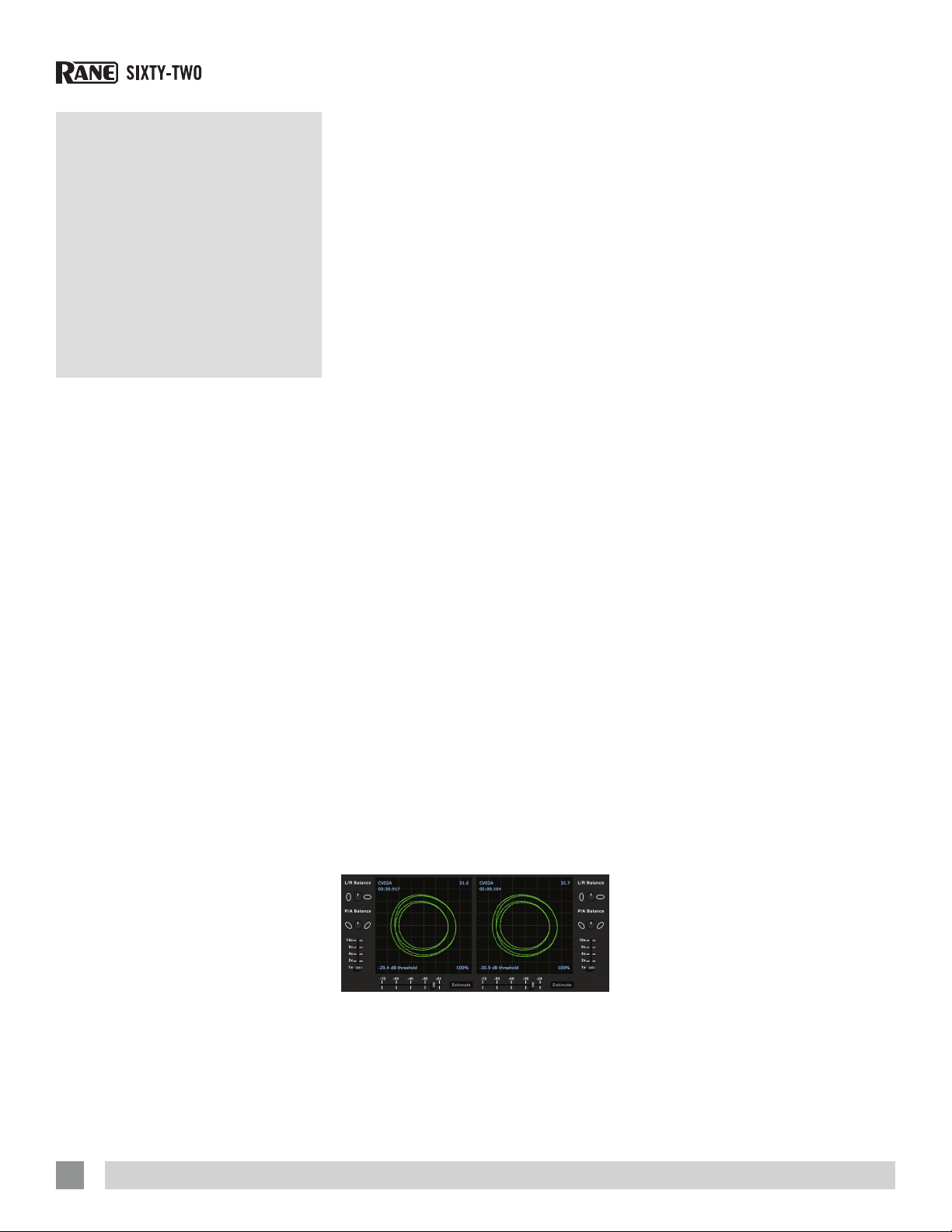
The Scopes
The scopes on the Setup screen in
Scratch Live display the input signal as a
phase diagram. The key factors to look at
on the scope display are crisp clean lines,
round shape, and the tracking percentage
in the lower right corner.
Start both turntables or CD players. You
will see green rings appear in the scope
view as shown.
For optimal performance the inner ring
should be as close to circular as possible.
Use the scope zoom slider (1x to 16x)
to zoom in or out as necessary. Use the
scope L/R Balance and P/A Balance
controls to adjust the shape of the inner
ring.
The number in the top left corner of the
scope view gives the current absolute
position within the control record or CD.
The number in the top right corner is the
current speed in RPM. In the bottom left
is the current threshold setting, and the
number in the bottom right shows the
percentage of readable signal — this
number should be close to 85% when
your system is calibrated properly.
Calibration Troubleshooting
After calibration, the number in the upper
right corner of the scope view should say
0.0 while the needle is on the record and
the turntable is stopped.
If that number is uctuating then
manually move the Estimate slider to the
right until that number is stable at 0.0.
If you’ve moved the slider all the way
to -24 and its still uctuating then you
have a grounding or interference problem
somewhere in the chain.
If so, the rst thing to check is that
the grounding wire coming from your
turntable is connected to a Sixty-Two
grounding post.
Next, make sure that the Sixty-Two isn’t
sitting next to a power source such as a
power strip and that the RCA cables aren’t
laying across other power-conducting
cables.
If you are still experiencing issues, you
might have to adjust the placement of
your setup. For example, make sure bass
bins aren’t directly under the turntables.
If you have trouble getting the rings
circular, you probably need to clean or
change your needles.
If the image appears as a line, then
you have a missing channel. Check your
RCA connections and needles. for more
calibration troubleshooting help See
“Scope Reading and Fixes” on page
48.
18
RAN E SIXTY-TWO MIXER FOR SERATO SCRATCH LI VE • OPER ATOR’S MANUAL 2. 5.0
Page 19

Importing and Playing Music
Importing Your Music
The easiest way to load music into your
library is by using the Files button:
1. Click on the Files button to open the
les panel. The left side of this window
displays various locations on your
computer hard drive (and external
drives if you have one). Click on these
locations to navigate your computer and
nd your music. By default, your music
will usually be found in either “Music”
(Mac) or “My Music” (Windows).
2. Once you have located your music,
drag the folder or les you want to
import onto the purple “ All...” icon.
This is located to the left of your screen
at the top of the crates and playlist
window. If you wish to import all of your
music, just drag your whole music folder
onto this icon.
TIP: You can also import by dragging
files and folders directly from Windows
Explorer (PC version) or Finder (Mac
version) into the Scratch Live library.
TIP: Adjust the
size of the Files
window by
clicking and dragging near the three
dots up or down. The vertical crates
window adjusts left and right.
Supported File Types
Scratch Live supports xed and variable
bit rate .MP3, .MP4, Ogg Vorbis, .AAC,
.AIFF, .ALAC, .WAV and Whitelabel (wl.
mp3) le types. M3U playlists are also
supported. For more on Whitelabel.net
audio les, see “Whitelabel.net” on page
20.
NOTE: Older iTunes Music Store DRM
files cannot be played back by Scratch
Live. iTunes Plus files are DRM-free.
Playing Music
Click on the “ All...” icon to show all the
tracks in your library. Use the keyboard
shortcut Shift - Left Arrow to load the
highlighted track on to the Left Deck, and
Shift - Right Arrow to load the highlighted
track on to the Right Deck.
TIP: You can also load tracks to Decks
using the mouse. Click and drag a track
from the track list area on to either
Virtual Deck.
To start playing a track, simply put
the needle on the record and start the
turntable. The track will start playing as
soon as it detects the signal from the
control vinyl (or CD).
In ABS mode, the track will play from
the position dictated by the placement of
the needle on the record. If you place the
needle at the beginning of the record, the
track will start playing from the beginning.
You can skip through the track by picking
up the needle and placing it further into
the record, just as with regular records
(this is known as needle dropping). See
“Scratch Live Modes” on page 24.
RAN E SIXTY-TWO MIXER FOR SERATO SCRATCH LI VE • OPER ATOR’S MANUAL 2. 5.0
Track Display
When a track is loaded, the track name,
artist and length are displayed in the track
title bar, and the Virtual Deck shows a
solid black line.
If the track has BPM or key information
written in the tag this will also be
displayed. See “Set Auto BPM” on page
20.
19
Page 20

Set Auto BPM
Whitelabel. net
The Serato Whitelabel Delivery Network is
a unique system that allows record labels
to digitally deliver promotional releases
directly to DJs.
To download Whitelabel audio les and
sign up to receive updates on the latest
promotional releases, visit whitelabel.net.
Whitelabel Audio Files
Whitelabel.net audio les are a unique
format (le extension wl.mp3) developed
by Serato. They are specially prepared for
use in Scratch Live; pre-analyzed, tagged
with song and artist info, BPM and album
art where possible.
Whitelabel audio les play as high
quality 320 kbps stereo audio in Scratch
Live when Rane Scratch Live hardware is
connected. Without Scratch Live hardware
connected, or when playing these les
through other mp3 software and devices,
they will play as low quality 32 kbps mono
audio.
Whitelabel audio les are promotional
releases from records labels available to
Scratch Live DJs for free from Whitelabel.
net.
Preparing Your Files
Before you play your music in Scratch
Live, It is important to rst analyze your
les.
The analyze les function processes
the songs in your library to detect le
corruption, saves the waveform overview
to an ID3 tag*, and calculates auto-gain
and BPM values.
How to Analyze Files
To analyze les run Scratch Live with the
Sixty-Two disconnected. On the left side
of the main screen, click the Analyze Files
button to automatically build overviews for
all the tracks in your library.
TIP: You can drag and drop individual
folders, crates or files onto the Analyze
Files button to force the building of
overviews at any time.
About Corrupt Files
If Scratch Live detects a corrupt
le it will tag it with a corrupt le
icon:
It is very important that you delete ANY
corrupt les from your library as they can
cause Scratch Live to crash regardless
if you play the le or not. See “Status
Icons” on page 37 and “Corrupt File
Descriptions and Diagnoses” on page
47.
If this option is checked while analyzing
les, Scratch Live will calculate the
estimated tempos of your les. If Scratch
Live is condent that the Auto BPM
estimate for a le is accurate, it will be
written to an ID3 tag* in the le. The Auto
BPM function will not be applied if the
track already contains BPM information.
To re-analyze these les and use Auto
BPM or auto gain, drag them onto the
Analyze Files button. If you know your
le’s BPM will fall within a certain range,
use the range drop down to avoid double
or half value BPMs being calculated.
*NOTE: ID3 tags contain data about
your tracks and are saved inside the
files themselves. Genre, track name
and artist are examples of common tag
information. See “Editing ID3 tags” on
page 37.
The Offline Player
The ofine player is a useful tool for
preparing crates, auditioning tracks, and
setting cue and loop points. The ofine
player is available when Scratch Live
hardware is not connected, and outputs
through the current default audio device.
Load a track to the ofine player by
dragging and dropping onto the Deck, or
pressing shift+left arrow. If the end of the
loaded track is reached, the next track in
the current playlist is played automatically.
Click the Ofine Player Controls button
(outlined below) to expand and hide the
ofine player controls.
20
For information on rescanning, moving,
copying, deleting and backing up your
les, see “File Management” on page
38.
RAN E SIXTY-TWO MIXER FOR SERATO SCRATCH LI VE • OPER ATOR’S MANUAL 2. 5.0
Page 21

Playback Control
The Control Record
The control record has two sides. The
rst side is 10 minutes long and contains
the Vinyl Scroll section. The second side
is 15 minutes long. Scratch Live can be
congured to work with records playing
at either 33 RPM or 45 RPM, depending
on your preference. The record has thin
marks every minute, and a thicker mark
every 5 minutes (when playing at 33
RPM). These marks are to assist you when
using needle dropping to move through
the track. These marks do not affect the
playback of the track.
The mode will switch when it reaches
the end of the record so your track won’t
stop. See “Absolute Mode” on page
25.
The Control CD
The control CD
has two tracks.
The rst track is 15
minutes long and
controls playback.
The second track
is 40 seconds long
and controls vinyl
scroll.
Vinyl Scroll
Vinyl Scroll allows you to select and load
tracks using only your turntables (or CD
player) – no contact with the computer
necessary! To use Vinyl Scroll with
turntables, lift the needle off the record
and drop it into special “bonus track”
section at the end of the record’s A side.
The movement of the control disk now
controls the selected track within your
library. Lift the needle out of the Vinyl
Scroll section of the record and into the
lead out (between the Vinyl Scroll area and
the end of the record) to change crates
or iTunes playlists. Go back to the Vinyl
Scroll area of the record to choose a track
within the crate or playlist. Once you have
found the track you wish to play, put the
needle back at the beginning of the record
and it will load automatically.
This feature is available to CD users.
Go to track 2 on the control CD to access
Vinyl Scroll. Find the track you want to
load, and go back to track 1. The track
you selected will be loaded and ready to
play. You can reverse the direction of Vinyl
Scroll and set the sensitivity in the Setup
screen.
TIP: You can also use Vinyl Scroll in the
Prepare window. See the options for
“Vinyl Control” on page 44.
Main Screen Overview
Virtual Deck
The Virtual Deck
shows everything
about the speed
and position of a
track. As the vinyl
rotates, so does
the line on the
label. The circular
progress bar around the edge is a visual
representation of the position within the
song, and can be set to ash to warn
you that the track is nearing its end. The
time and remaining time are displayed in
minutes and seconds. The pitched BPM
(BPM with pitch adjustment multiplier
added) is shown on the left of the Virtual
Deck, and the turntable speed as a
percentage pitch shift is shown on the
right of the Virtual Deck. If the track has
no BPM information, pitched BPM will not
be shown.
If you are playing regular vinyl, notice
the Virtual Deck behaving strangely as
Scratch Live attempts to decode the
incoming signal. This will not cause any
problems, but you may nd it distracting.
You can unload the currently loaded track
using the Virtual Deck eject button.
RAN E SIXTY-TWO MIXER FOR SERATO SCRATCH LI VE • OPER ATOR’S MANUAL 2. 5.0
TIP: Use the keyboard shortcut shiftalt-arrow to unload a track from the
Virtual Deck.
21
Page 22

Visual Aids
When the track is playing several
waveforms are displayed. Each shows a
different aspect of the track being played.
Tempo Matching Display
The Tempo Matching display area
provides a helpful tool for beat matching.
Scratch Live detects the beats within the
track, and places a row of orange peaks
(for the track on the left side) above a
row of blue peaks (for the track on the
right side) in the Tempo Matching display
area. When the two tracks are matched
to the same tempo, the peaks will line
up. The tempo display is aligned with the
beginning of the bar, so the peaks keep
their relative position as the track plays.
This display does not show the relative
timing of the beats, only the tempos of the
tracks. The peaks will still line up when the
tracks are playing at the same tempo, but
are out of sync.
Track Overview Display
This view provides a complete
overview of the track waveform,
and includes a marker to show
the current position within the
track. This view is useful for
nding transitions within the
track. The waveform is colored
according to the sound spectrum
– red representing low frequency
bass sounds, green representing
mid frequency sounds and blue
representing high frequency treble
sounds.
You can jump to different
positions within the track by
clicking on the Track Overview display
(disabled in ABS Mode). Grey lines behind
the overview show the length of the track
– a thin grey line every minute, and a thick
grey line every 5 minutes. The overview
will be lled when you load the track onto
a Virtual Deck. On slower computers,
you should disable Autofill overviews in
the Library tab of the Setup screen. See
“Preparing Your Files” on page 20
and “AutoFill Overviews” on page 45.
Main Waveform Display
This view provides a
close-up of the track,
including color coding to
show the frequency of the
sound; red representing
low frequency bass,
green representing
mid-frequencies and
blue representing highfrequency treble sounds.
You can also switch to a
three-band spectrum view
by holding the ctrl key and
clicking on the waveform.
Click on the waveform to
‘scrub’ or make ne adjustments to your
position within the track. This applies
to INT Mode only, and may be useful if
you wish to set cue points in your tracks
without your turntables or CD players
connected. The Main Waveform is
zoomed around the current position in the
track. See “Cue Points” on page 26
and “Scratch Live Modes” on page
24.
TIP: Use the + and – keys to zoom in
and out.
TIP: Waveform can be either vertical or
horizontal. See “Display Modes” on page
24.
Kick Drum
In this example, the red part
of the wave represents a kick
drum, while the purple part
represents a snare drum.
Snare Drum
Beat Matching Display
This view shows the position
of beats within the track. When
beat matching, this view helps
align the downbeats of the two
tracks. The markers are matched
up when the two tracks are beat
matched.
Example: The following is a
demonstration of using the visual
aids to help beat match. In this
example, the track that is playing
is on the Left Deck, and the track
to be mixed in is on the Right Deck.
1. Start the track playing on the Right
Deck. After a few seconds, blue peaks
appear in the Tempo Matching display.
2. Adjust the pitch of the right turntable
until the blue peaks sit under the orange
peaks in the Tempo Matching display.
Once they are aligned, the two tracks
have the same tempo.
3. Next align the markers in the Beat
Matching display. Watch the color of the
items passing by in the Main Waveform
display. Remember that a kick or
bass drum will be red in color, and a
snare drum will be green or blue. This
technique will by no means guarantee
perfect mixes, but may help to speed up
the process of beat matching.
Master Gain
The master output of Scratch Live
can be controlled using the master
gain control. This adjusts the
volume of all tracks played. Ctrl-click the
knob to reset it to 12 o’clock.
NOTE: For best results, set the master
gain to 12 o’clock, and adjust the
volume of individual tracks using the
track gain adjustment.
33 / 45 Speeds
Set this to match the speed
of your turntable for normal
playback.
22
RAN E SIXTY-TWO MIXER FOR SERATO SCRATCH LI VE • OPER ATOR’S MANUAL 2. 5.0
Page 23

Tracking Indicator
The tracking
indicators on the
main screen show the quality of the signal
coming from the control record or CD. The
length of the bar indicates the speed of
the record or CD. The color indicates the
amount of position information Scratch
Live is receiving. When you are playing
the record at normal speed, the tracking
indicator should be grey. If it is mostly
red there is a problem reading the control
signal. Make sure your needles are clean,
and check the calibration in the setup
screen.
NOTE: It is normal for the tracking
indicator to be red when cueing or
scratching.
Tap Tempo
For tracks with no BPM
information, there is a tap tempo
button displayed where the BPM usually
is, in the song info area. Pressing altspace bar activates the tempo tapper
(press alt-space bar a second time to
activate the tempo tapper on the Right
Virtual Deck). Tap the space bar along
with the beat. After you’ve tapped the
rst beat, you can switch to double time
tapping, half time, start of each bar etc.
The range is set by the rst two taps, after
that you can switch to any steady rhythm
you feel comfortable with – quarter notes,
half note, whole notes. Esc resets the
BPM, Enter saves the BPM to the track.
You can use the mouse if you prefer.
Your CD player or turntable’s pitch slider
doesn’t need to be at zero, we do the
math for you. You can also use the tempo
tapper when no song is loaded, for nding
the BPM of regular records, for example.
Eject
This ejects the track playing or
loaded from it’s Virtual Deck.
Key Lock
When Key Lock is on, the key or
pitch of the song stays locked at
what it would be if the track was playing
at normal speed, regardless of the platter
speed of the turntable or CD player. Key
Lock has scratch detection, so that it
automatically turns off when scratching
for a natural scratching sound. Turn Key
Lock on or off by clicking the button to the
top right of the Virtual Deck.
TIP: F5 and F10 will turn Key Lock on
and off for the Left and Right Decks
respectively.
Repeat
Use the Repeat function to repeat
the song across the entire length of
the control record.
TIP: Short “loop” samples can be
turned into a continuous track using
the Repeat function. The loops must be
less than 10 seconds long, and cut at
the start and end of a bar.
Censor
Use the censor button to ‘mask’
parts of a song, or use as a special
effect. When you press the censor button,
the track starts playing backwards from
that point. When you release the censor
button, the track plays forward from the
point you would have been, had you not
pressed the censor button. Censor is
available only in REL and INT Modes.
Autoplay
Click the Auto button to enable
autoplay. With this setting turned
on, when one track nishes playing, the
next track starts automatically. Load from
a crate to play through the songs in that
crate, or from your library to play through
your library. Autoplay works in both REL
and INT modes. Play from start must be
checked in the Playback tab of the Setup
screen for autoplay to work correctly. See
“Play From Start” on page 43.
Track Gain
Use the track gain knob to balance
the volume of the tracks in your
library. Any adjustment made to the
gain of a track is saved with the le,
and will be reapplied to the entire
track when it is loaded again. The
level meter shows the level sent to
the hardware interface after both
individual track gain and master
gain adjustment. Ctrl-click the knob to
reset it to 12 o’clock.
NOTE: For automatic gain setting of
your tracks, see “Use Auto Gain” on
page 43.
USB Dropout Indicator
The USB dropout
indicator on the main
screen is a useful
trouble shooting
tool if you have problems with audio
dropouts. Such dropouts are caused by
an interruption in passing the audio to the
Scratch Live hardware interface. If such an
interruption (or dropout) occurs, a red light
will appear briey, just to the left of the
Scratch Live logo at the top of the screen.
The light will be red for one second, and
then orange for four seconds.
If you experience USB drop outs:
• Increase the USB Buffer Size See “USB
Buffer Size (Latency)” on page 42.
• Try closing other applications that are
running at the same time as Scratch
Live.
• Try turning off background tasks, for
example, wireless networking.
• If your CPU load is very high, try
decreasing the Maximum Screen
Updates setting in the Display tab of the
Setup screen. See “Maximum Screen
Updates” on page 45.
RAN E SIXTY-TWO MIXER FOR SERATO SCRATCH LI VE • OPER ATOR’S MANUAL 2. 5.0
23
Page 24

Display
Library
Scratch Live
Modes
Scratch Live gives you the option of
four different display modes to suit your
style of performance. The Display Mode
buttons are located in the top left of the
Main Screen. They are:
Library Mode: Maximizes your
library space by minimizing the
Virtual Deck information displayed. In
Library Mode only the track information,
Virtual Deck, mode, track overview display
and meter are displayed.
TIP: Use the space bar to toggle
between Library Mode and your current
display mode.
Views
You can choose between four different
library views which allow for visual
browsing using text and album art. Select
your Library View by using the buttons in
the bottom left area of the main screen.
The available Library Views are:
Simple List: Displays the track
information in a text list.
Album Art List: Adds an album art
column to the Simple List mode.
Album Art Grid 1: Displays the
album art as a grid with the track
information text to the right.
Modes
Scratch Live has three different modes of
operation. You can switch between these
modes by clicking the mode buttons near
each Virtual Deck.
Classic Vertical Mode: Two
Decks are displayed on the left
and right sides of the screen with vertical
waveforms in the middle.
Classic Horizontal Mode: Two
Decks are displayed on the
left and right sides of the screen with
horizontal waveforms in the middle.
2-Deck Stack Mode: Two Decks
are stacked on top of each other
in a horizontal fashion. Stack Mode aligns
the waveforms on top of each other, while
maximizing waveform space. The controls
for all Decks can be shown or hidden by
pressing the Show Deck Controls Button
on any Deck.
Album Art Grid 2: Displays the
album art as a grid with the track
information text below.
NOTE: Your files must have album
art added for it to be displayed. See
“Adding Album Art” on page 37.
TIP: For all views you can adjust the
font size by using the Font Size slider in
the Library tab on the Setup screen. For
all Album Art views you can adjust the
album art size using the Album Art Size
slider in the same area.
24
RAN E SIXTY-TWO MIXER FOR SERATO SCRATCH LI VE • OPER ATOR’S MANUAL 2. 5.0
Page 25

Absolute Mode
Relative Mode
Internal Mode
ABS mode is the default mode, and
most closely resembles the properties of
normal vinyl. The beginning of the track
is mapped to the start of the record, and
by picking up the tone arm and moving
the needle to another part of the record
(needle dropping) you can move to a
different position within the track.
ABS mode faithfully reproduces the
movement of vinyl control records,
including stops, starts, scratching, needle
dropping, rubbing and other turntablist
techniques.
When you reach the end of the record
using either REL or ABS modes, Scratch
Live automatically switches to INT mode.
This is known as Emergency Internal
mode, and prevents long tracks from
stopping when you run out of record.
You can switch from Emergency Internal
mode to ABS mode by lifting the needle
and placing it in the lead-in of the control
record. Emergency Internal mode will
activate after 1 second. Use the keyboard
shortcut F1 (left deck) or F6 (right deck) to
switch to ABS mode.
NOTE: Be careful when scratching
near the end of the record not to
accidentally go past this point and
into internal mode, or the track will no
longer respond to record movement!
REL mode observes the relative forward
and backward movement of the record,
but does not take into account the
position within the record. REL mode
disables needle dropping, but allows skipfree scratching.
See: “Drop To Absolute Position” on
page 44.
REL mode adds additional speed
controls:
Previous track – Go to the previous
track in the list.
Rewind - The rewind function
speeds up the longer you press the
button.
Fast forward – The fast forward
function speeds up the longer you
hold the button.
Next track – Jump to the next track
in the list.
TIP: Use the keyboard shortcut F2 (left
deck) or F7 (right deck) to switch to
REL mode.
INT mode allows playing tracks without
external vinyl (or CD) control. INT mode
has a start / stop function and a virtual
pitch slider. Holding down the shift key
moves the pitch slider slowly. Holding the
ctrl key and clicking on the pitch slider
resets the pitch to zero.
Scratch Live automatically switches
to INT mode when the end of the control
record is reached; you can switch back
to REL mode by placing the needle in the
rst ve minutes of the control record.
If you switch from ABS or REL into INT
mode, Scratch Live automatically adjusts
pitch to maintain playback speed as
set by the turntable. Use the keyboard
shortcut F3 (left deck) or F8 (right deck) to
switch to INT mode.
INT mode adds these additional controls:
Play / pause reverse - Press to
play, press again to stop playback.
You can adjust the braking knob in the
setup screen to range from an immediate
stop to a slow turntable-style ‘power
down’. See “Braking” on page 43.
Play / pause forward - Press to
play, press again to stop playback.
Uses the same braking as described
above.
RAN E SIXTY-TWO MIXER FOR SERATO SCRATCH LI VE • OPER ATOR’S MANUAL 2. 5.0
Bend down - Create a temporary
decrease in the playback speed.
Use bend down if the two tracks are in
time, but this track is slightly ahead of the
other track.
Bend up - Create a temporary
increase in the playback speed. Use
bend up if the two tracks are in time, but
this track is slightly behind the other track.
25
Page 26

Pitch Slider - Use the pitch
slider to make pitch adjustments
while using INT mode. Drag the
pitch slider with the mouse to
make large pitch movements,
or hold the shift key and drag
the pitch slider to make ne
adjustments.
Clicking the RANGE button
above the slider changes the
slider range to ±8%, ±10%, ±16%, ±50%
or ±100%.
Temporary Cue
There is a temporary cue point that can be
used like the cue button on many DJ CD
players. Press ctrl-I to set this temporary
cue point on the Left Deck, and ctrl-K to
set it on the Right Deck. This temp cue
point is shown in the main waveform as a
white marker. This cue point is not saved
with the track, and by default is set to the
beginning of the track. Press I to jump to
this temporary cue point on the Left Deck,
and K for the Right Deck. If you hold down
the I or K key while the track is stopped, it
will play from the temporary cue point. As
soon as you release the key, it will jump
back to the temporary cue point. Note
that you can use this shortcut to jump to
the beginning of the track if the temporary
cue point has not been set. See “Cue
Points” on page 26.
More Controls
You can also control playback using the
computer keyboard shortcuts — turn
Caps Lock on to enable. See “Playback
Keys Use Shift” on page 43.
Left
Deck
Q play / pause reverse A
W play / pause forward S
E pitch down D
R pitch up F
T bend down G
Y bend up H
Alt-Q load previous track Alt-A
Alt-W load next track Alt-S
Alt-E rewind Alt-D
Alt-R fast forward Alt-F
Ctrl-I
Click on the waveform to ‘scrub’ or make
ne adjustments to your position within
the track. This may be useful if you wish
to set cue points in your tracks, and
don’t have your turntables or CD players
connected.
NOTE: If you play a track in INT mode,
and then switch to ABS or REL mode,
the pitch adjustment will be dictated by
the turntable, so there will be a jump in
pitch unless they are already perfectly
matched.
TIP: If you are in ABS or REL mode and
you get a build up of dust on the needle
that is breaking up the audio, hold
down ctrl and press the INT button.
This will take you to INT mode and
reset the pitch to zero.
Function
set a temporary cue
point
Right
Deck
Ctrl-K
Cue Points
Use cue points in Scratch Live to mark
and trigger different parts of your tracks.
The cue point markers are saved with the
le in the track’s ID3 tag. This means they
will be present each time you load the
track.
Setting Cue Points
You can set up to ve cue points for each
track. Click on the + button to place a
cue point, or use the keyboard shortcuts
below. A cue point will be set at the
current playhead position of the track and
can occupy any of the 5 slots.
Use the keyboard shortcuts: ctrlcomma (for left) and ctrl-period (for right)
to place cue points in chronological order.
Alternatively, use ctrl-1 through 0 to set a
specic cue point, i.e., to set a cue point
on the Left Deck in slot 2, press ctrl-2.
Notice the stripe on the Virtual Deck
jumps to the 12 o’clock position and
changes color when you set a cue point
– you are at the cue point when the stripe
is one solid color and at the 12 o’clock
position. As the track plays on beyond the
position of the cue point, the colored bar
shortens by a fth for each rotation.
Likewise, as you approach the cue point,
the color will grow by a fth each rotation.
For example, the picture below shows the
track just before the end of the 5th
rotation before the cue point.
26
RAN E SIXTY-TWO MIXER FOR SERATO SCRATCH LI VE • OPER ATOR’S MANUAL 2. 5.0
Page 27

TIP: Zoom in on the waveform using the
– and + keys and ‘scrub’ to the desired
position for greater accuracy when
setting cue points.
Enable Hot Cues
To turn on hot cues, check Enable Hot
Cues in the Playback tab on the Setup
screen. When Hot Cues are enabled, you
can set cue points simply by pressing the
number keys 1 through 0 (no ctrl modier
required). Note that you can only add cues
this way if the cue point slots are empty.
See “Enable Hot Cues” on page 43.
Triggering Cue Points
Click the arrow to the left of each cue
point to jump to it (REL and INT modes
only). You can also jump to cue points
using shortcuts: 1 through 5 for the cue
points on the Left Deck, and 6 through 0
for the Right Deck cue points.
Editing Cue Points
To remove a cue point, use the x button
on the right side of the cue point panel.
You can also overwrite cue points by
using the shortcut keys ctrl-1 through 0.
Customizing Cue Points
To change the color of a cue point, click
on the colored square and choose a new
color from the drop down menu.
To name your cue point, double click
on the “time” eld. You can now edit and
name this cue point to whatever you like.
You can also drag and drop cue points
to change their order in the list. If you wish
to have the cue points sorted by time,
check Sort cues chronologically in the
Playback tab on the Setup screen. If you
load the same track onto both Decks, you
will be able to add or modify cue points
from either Deck.
When you jump to a cue point in INT
mode while paused, the track will play
from the cue point for as long as the key
or mouse button is pressed, after which
the playhead returns to the cue point. If
this is done using the keyboard while the
track is playing in either INT or REL mode,
the cue point will be repeatedly triggered,
producing a stuttering effect.
Looping
You can save up to
9 loops per track.
These loops are
saved in the le, and will be present when
you reload the track. To make a loop, set
the in-point by clicking the IN button, and
the out-point by clicking the OUT button.
To turn the loop on or off, click the LOOP
button. If you want the playhead to jump
to the start of the loop when you enable
the loop, hold the control key and press
the LOOP button.
To adjust the in-point of the loop, click
the IN button. You can use the arrow keys:
left arrow to move the in-point towards
the start of the track, right arrow to move
the in-point towards the end of the track.
Hold down the shift key while pressing the
arrow key to make coarse adjustments.
Click the IN button again to save the inpoint. The same applies to adjusting the
out-point.
You can also use the control vinyl (or
CD) to adjust the in- and out-point. Click
the IN button, then move the control vinyl.
Moving the vinyl will adjust the in-point.
Once you are happy with the new in-point,
click the IN button again to save, and
release the control vinyl.
The control vinyl will go back to
controlling playback once the record
is back up to normal speed. Using the
control vinyl to adjust loop end points is
optional — to turn this feature off, disable
Adjust loops with vinyl under the Vinyl
Control tab in the Setup screen.
There are 9 available loop slots per
track. If a loop is set in a given slot, the
background (behind the loop number)
will be green. Press the x button to clear
the loop. If you click on the locked loop
symbol, a red border will appear. This
indicates the loop is locked, and you
will not be able to adjust the end points
or delete the loop until you unlock it, by
clicking on the number again.
NOTE: Looping applies to REL and INT
modes.
Auto-Looping
Auto-looping
allows you to
create loops
instantly. If
the track has
a BPM value simply click the number of
beats you wish to loop and Scratch Live
will create the loop for you. The loop is
snapped to the beats in the song detected
by Scratch Live so even if you press the
button slightly out of time Scratch Live will
still create a perfect loop for you.
Five auto-loop buttons are available on
screen at any one time. They range from
1/32 to 32 beats. The user can select
the auto-loop range with the and
buttons.
Pressing an auto-loop button will create
a loop start point from the nearest beat
to the playhead (within reason), and set
a loop endpoint in the future. Pressing
auto-loop 1 while auto-loop 1 is active will
deactivate the loop. Pressing a different
auto-loop button while looping is active
will extend the endpoint of the current
loop to the appropriate new auto-loop
length.
You can also save an auto-loop to the
next available slot. When using an autoloop, a save button is visible where
the lock loop button normally is.
NOTE: Auto-looping requires the track
BPM to be set. See “Set Auto BPM” on
page 20.
RAN E SIXTY-TWO MIXER FOR SERATO SCRATCH LI VE • OPER ATOR’S MANUAL 2. 5.0
27
Page 28

The A-Slot
A special loop slot ‘A’ exists for autolooping. The act of using the auto-loop
buttons sets a loop in the ‘A’ slot,
following the rules above. Turning a
loop off using the auto-loop buttons
returns you to the loop slot that you
were previously in at the time you started
auto-looping. Turning the loop off using
the LOOP button leaves you in the ‘A’
slot. The ‘A’ slot is not saved to disk
automatically, pressing ‘save’ saves the
loop to the rst empty slot in 1-9.
Auto-looping shortcut keys are alt-1
to 5 for the Left Deck, and alt-6 to 0 for
the Right Deck. They correspond to the
looping buttons as laid out on screen. ie.
if the onscreen buttons display 1 2 4 8 16
beat loops, alt-1 triggers a 1 beat loop,
and alt-5 triggers a 16 beat loop.
Loop Roll
Loop roll performs a standard autoloop, but when the loop is turned off,
the playback position is returned to the
position where it would be if it had not
entered the loop (much like censor).
The other difference between loop
roll and standard auto-loop is the ‘‘roll’’
button is momentary. The loop is engaged
when the button is pressed down, and
disengaged when the button is released.
Use short loop lengths to create “stutter”
type effects.
To activate loop roll, hold control + alt
while clicking on the desired autoloop
increment, or use the keyboard shortcuts:
control + alt + 1 through 5 for the Left
Deck and control + alt + 6 through 0 for
the Right Deck. (ie. the same as the autoloop controls with the additional ‘alt’ key
as a modier).
The range of values available for loop
roll are 1/32 through to 32 beats. The
shortcut keys will activate whichever loop
lengths are visible on screen, i.e., if you
have lengths of a 1/4 beat through to 4
beats visible for the Left Deck, control +
alt + 1 will activate a 1/4 beat loop roll,
control + alt + 2 will activate a 1/8 beat
loop roll and so on.
Use the and buttons to toggle
through the range of possible lengths
visible onscreen.
Loop Roll with MIDI
You can assign loop roll to MIDI two ways:
1. After pressing the MIDI assign button
in Scratch Live, press the control + alt
keys, click on an auto-loop value, then
click on the button/slider you want it
mapped to on your MIDI controller.
2. You can assign the singular loop roll
button to MIDI, then assign a MIDI
knob or slider on your controller to the
autoloop select knob (visible in the MIDI
assign panel area when in MIDI assign
mode) to change the values on the y.
TIP: When you have the “Autoloop
Select” knob assigned to MIDI, you
have all of the loop roll lengths at your
disposal. This allows you to roll up and
down the loop length scale, to create
interesting stutter and build-up effects.
NOTE: Like auto-loop, loop roll requires
a BPM value written to the ID3 tag in
order to work. Build overviews with the
“Set Auto BPM” box checked and the
proper range for your music selected
to ensure an accurate BPM value. See
“Set Auto BPM” on page 20
To use the Loop controls on the SixtyTwo, see ”Loops Manual / Auto” on
page 10.
SP-6 Sample Player
The SP-6 Sample Player allows you to
play up to six sources of audio, in addition
to the tracks playing on the Virtual Decks.
Any audio le in your Scratch Live library
can be loaded to any one of the six slots,
allowing playback of short samples,
sound effects, or full length tracks.
The SP-6 is enabled when the SixtyTwo is plugged in, but not operational in
the ofine player mode.
Click on the SP-6 button to access the
sample player window.
In the top right corner of
the SP-6 there is a
button which opens the
Display Menu. Clicking
on this drops down a
menu with the list of
available controls:
• Mode: Chooses the play mode: Trigger
/ On-Off / Hold / Repeat modes.
• Output Select: Assigns individual slot
outputs to L (Left channel), A (Aux
output), R (Right channel) or to the
master output of the SP-6.
• Pitch: Pitch Slider / Bend / Nudge /
Keylock controls.
• Play from: Choose which cue point /
loop to use for the loaded track.
• Overview: Displays the overview of
each track.
• Level: Individual sample slot level and
Gain controls.
• Level meter: Displays the volume level
for the sample slot.
This enables you to set up the sample
player with the appropriate controls that
suit your workow.
28
RAN E SIXTY-TWO MIXER FOR SERATO SCRATCH LI VE • OPER ATOR’S MANUAL 2. 5.0
Page 29

Loading the SP-6
To load a track to the SP-6, drag and drop
the desired le from your library into one
of the sample slots. To eject a track, click
the eject button to the right of the title
display.
TIP: You can load tracks to the SP-6
with the keyboard shortcuts: ctrl + alt +
z to n.
TIP: Select and drag six tracks from
your library onto the first sample player
slot to simultaneously load six tracks
across all six slots.
Playing Samples
Pressing the play button on each
slot will play the loaded audio.
TIP: Use the shortcut keys
z (slot 1) x (slot 2) c (slot 3)
v (slot 4) b (slot 5) n (slot 6)
to trigger each sample respectively.
SP-6 Instant Doubles
You can instant double from the Virtual
Decks down to the SP-6, from the SP-6
up to the Virtual Decks and also between
the sample slots themselves. This means
the position, track gain and speed will
match when you drag a track to from one
location into another. This allows you to
beat match tracks with your turntables/
CD players on the Virtual Decks, and
then “instant double” the track down to
a slot, freeing up the Virtual Decks to
continue your mix with other tracks. Click
and drag an already playing track from
a Virtual Deck or sample slot and drop it
on another sample slot to begin instant
doubling.
SP-6 Play Modes
Each sample slot has three different play
modes:
Trigger mode - When play is
pressed, the audio plays through
until the end of the track. Pressing
repetitively will trigger the audio from the
beginning of the track. To stop the audio,
hold the alt key while either clicking the
play button, or pressing the corresponding
shortcut key (e.g., alt - z for slot one).
Hold Mode - The sample will only
play while you press and hold the
play button or the corresponding shortcut
key. Upon release of the play button, the
audio stops immediately. This mode most
closely resembles the function of the
“note off” mode found on many samplers.
On / Off Mode - When play is
pressed, the audio plays through
until the end of the track. Pressing play
again stops the audio.
Repeat Mode - Each slot has a
repeat button. When activated,
this will repeat the loaded audio le from
beginning to end, or will turn on the loop
selected in the “Play From” eld.
TIP: Short “loop” samples can be
turned into a continuous track using
the repeat function. Ensure there is a
clean cut at the start and end of a bar.
TIP: If you don’t wish to use the SP-6,
you can disable it in the Plugins tab on
the Setup screen.
SP-6 Pitch Controls
There are
individual
Pitch Slider,
Bend,
Nudge, and Keylock controls for each
sample slot. The BPM is also displayed
next to the pitch slider. If no BPM is
present in the tracks ID3 tag, the pitch of
the track is displayed as a percentage.
Click and drag the pitch slider to make
regular pitch adjustments. Hold the shift
key and move the pitch slider to make ne
pitch adjustments.
Click on the + and – buttons to nudge
the track into time. (temporary pitch
adjustment)
Hold the ctrl key and click the + and
– buttons to make ultra-ne pitch
adjustments to nudge the track, adjusting
the pitch permanently.
SP-6 ‘Play From’ Selector
Use the
“Play From”
selector to choose where the track will
play from. You can choose to play a
track from the start of the le, any one of
the cue points, or any one of the loop in
points.
When this is set to play from start, or
play from a cue point, the track will play
right through until stopped. When a loop is
selected, the track will play until the loop
out point, unless you have “repeat” on, in
which case the track will loop using the in
and out points of the selected loop.
The number of options will be
dependent on the number of cue points
and loops already set in your track. i.e
if the track loaded has no cue points
and loops set, then only “start” will be
available as a “Play From” option.
TIP: To set or adjust cue and loop
information for a track, load it to a
Virtual Deck, make your adjustments,
then load it back into the sample slot.
RAN E SIXTY-TWO MIXER FOR SERATO SCRATCH LI VE • OPER ATOR’S MANUAL 2. 5.0
29
Page 30

SP-6 Track Overviews
Displays an
overview of
the track loaded to each sample slot. The
waveform, play head position, cue points
and selected loops will all be visible.
SP-6 Slot Volumes
Each
individual
sample
slot has a
separate volume slider and gain control.
Volume Sliders - Use the volume slider to
mix and make temporary adjustments to
the volume of the sample you are playing.
These sliders act like your mixer’s,
fading from full volume right through to
completely silent.
Gain Knobs - In addition to the volume
slider there is an additional gain knob for
each slot. These allow you to ne tune
the maximum gain volume of the loaded
sample. The gain adjustment will also be
written to the track’s ID3 tag, meaning that
it will be the same everytime you load it.
SP-6 Output Selector
Use the master output
selector button to choose
where you wish to have
the SP-6 output to.
L to PGM 1 with
as the PGM Source.
A to
R to PGM 2 with
as the PGM Source.
There is also a master sample
player Gain knob to adjust the
overall SP-6 volume.
AUx.
A or B selected
A or B selected
Individual Output Selectors
By default
each sample
slot will be set to Master, mirroring the
SP-6 master output setting. You can
however, use the individual output
selector buttons to override the Master
output setting.
To send an individual slot to a different
output from the Master, deselect the
master option by clicking on the MASTER
button for the corresponding slot.
This will unlink the sample slot from the
master sample player output selection,
allowing you to choose the 1, 2, 3 or 4
PGM output for each slot. These output
routings will be saved when you close
down Scratch Live, so the next time
you launch Scratch Live, your preferred
settings will remain the same.
SP-6 Sample Banks
The SP-6 has four separate
sample banks, labeled A, B,
C and D. To switch between
the different banks click on the A, B, C
or D buttons. Each bank will save the
individual sample and sample slot settings
you last used, allowing you to prepare
banks for easy recall at a later stage.
Sample Bank A will load as the default.
SP-6 Mute Buttons
Use the mute buttons to mute the
audio output for each of the SP-6’s
sample slots. Click the mute button to
silence the audio output, click the mute
button again to turn the audio back on.
You can also ctrl-click on the mute
buttons to mute the outputs momentarily,
meaning that the audio will only be muted
for as long as you hold your mouse click.
TIP: You can MIDI assign these buttons,
allowing you to create a virtual kill
switch for the sample slot. To MIDI
assign momentary mute, hold ctrl and
click on the mute button before tapping
your MIDI controller.
SP-6 MIDI
All features of the SP-6 are MIDI
assignable. The SP-6 window must be
opened rst before enabling MIDI assign
mode. See “MIDI Control” on page
32.
To trigger samples from the Sixty-Two,
see “Cues / Samples control” on page
10.
DJ-FX Plugin
The DJ-FX Plugin gives you control of
two FX units, each with three chained
effects slots per unit. Each FX unit has
two control modes: Ultra Knob Mode and
Super Knob Mode, both of which can be
fully customized. The DJ-FX plugin opens
in Ultra Knob Mode by default.
The DJ-FX Plugin must be enabled in
the Plugins tab in the setup screen. Once
enabled, the DJ-FX panel button appears
in the panels area on the main screen.
See “Enable DJ-FX” on page 45.
To enable post-fader DJ-FX with the
INSERT button, see “Enable Mixer
DJ-FX Send” on page 45
NOTE: The DJ-FX plugin is not visible
if your Rane hardware is not connected.
Ultra Knob Mode
Click the Ultra Knob Mode
button to select Ultra Knob
Mode. This allows you to control up to
three effects slots in one FX unit using the
one Ultra Knob.
Click on the drop down menu to load an
Ultra Knob effect. (This is “empty” before
settings are saved in Macro Edit Mode.)
Click the ON button to enable the effect,
and use the Ultra Knob to control the wet
and dry amount of all effects.
Click the Show Parameters button
to show the effects and parameters
that are controlled by the loaded
Ultra Knob preset.
30
RAN E SIXTY-TWO MIXER FOR SERATO SCRATCH LI VE • OPER ATOR’S MANUAL 2. 5.0
Page 31

Super Knob Mode
Super Knob Mode allows you
individual control of each effect
in the FX unit. Each effect slot has a Super
Knob which controls the wet and dry
amount for the effect.
Click the Effects drop down box to
select an effect for the effect slot. You can
leave a slot empty by selecting “empty.”
Click the ON button by the Super
Knobs to toggle turning the effect(s) on
and off.
The effects chain works in series going
from effects slots 1 to 3, meaning that the
effected audio from slot 1 passes through
slot 2, which is then passed through slot
3.
Effects BPM Multiplier
The Effects BPM
Multiplier is used
to adjust the effect time. The effect time
is set using the track’s BPM value, but by
applying the Effects BPM Multiplier you
can increase or decrease the effect time.
Deck Assign
You can select which Deck the FX unit
applies to by clicking the Deck buttons.
Each Deck can only pass through one FX
unit at a time. You can assign the SixtyOne PGM FlexFX buttons control DJ-FX:
in the Plugins tab of the Setup screen,
turn on “Enable Mixer DJ-FX Send” on
page 45. The software Deck buttons
are not visible with this enabled.
Show Parameters
Press the Show Parameters
button to expose the individual
parameters for each effect. You can
then control the individual parameters by
adjusting their respective knobs.
In Ultra Knob Mode, use this to select
which effects are loaded and controlled by
the Ultra Knob.
In Ultra and Super Knob Mode, you
can link or unlink a parameter to the
Super Knob by pressing the Link Button,
allowing one master control of some
parameters and individual control of
others.
Macro Edit Mode
Macro Edit Mode is an advanced
option that allows you to create
macro mappings for each effect and to
save any effects edits made in Ultra or
Super Knob Mode. Open Macro Edit
Mode by clicking the Macro Edit Button
while Show Parameters is open. Once
opened, more controls appear which
allow you to create and change parameter
mappings.
To map a parameter to the Ultra or Super
Knob:
1. Unlink the parameter that you
want to map to the knob. The
Macro Min and Max buttons for this
parameter are now displayed.
2. Move the Ultra or Super Knob to
the position that you want the
parameter to start mapping from.
3. Move the Parameter Knob to the
position that you want the to be
the lowest value of the parameter.
4. Press the Macro Min button to set
the minimum position.
5. Move the Ultra or Super Knob to
the position that you want the
parameter to end being
controlled from.
6. Move the Parameter Knob to the
position that you want the to be
the highest value of the parameter.
7. Press the Macro Max button to set
the maximum.
8. Link the parameter to the Ultra or
Super Knob by pressing the Link
button.
Now when you adjust the Ultra or Super
Knob you will see the parameter knob
move within the range that you just
specied. Any parameters not customized
but linked to the Super or Ultra Knob will
behave as normal.
You can save any macro
mappings you have made to
an effect by clicking the Save button
by the Super Knob, and save effects
combinations made in Ultra Knob Mode
by clicking the Save button by the Ultra
Knob.
RAN E SIXTY-TWO MIXER FOR SERATO SCRATCH LI VE • OPER ATOR’S MANUAL 2. 5.0
31
Page 32

MIDI Control
The MIDI Control feature in Scratch Live
provides the ability to map MIDI controls
to Scratch Live controls, and thus control
the functions of Scratch Live using MIDI
controllers such as keyboards, triggers,
sliders, and knobs. Integrating MIDI
controllers into your Scratch Live setup
can improve live performance usability,
such as hitting pads on a MIDI controller
to trigger loops and cue points.
MIDI Controller Setup
The process of setting up a MIDI
controller for use with Scratch Live
will vary depending on the hardware in
question. Many devices can connect to
a computer using MIDI over USB, and
will either be supported directly by your
operating system, or require installation of
drivers and conguration utility software.
Follow the manufacturers instructions for
installation.
Other controllers may solely use a MIDI
out connector to send control messages,
and will require a separate MIDI interface
unit to communicate to software.
Generally the MIDI interface will come with
drivers and conguration tools which pass
your controller’s output onto an available
MIDI channel, which can be used by
Scratch Live.
Once your controller is installed and
functioning correctly, use these directions
for assigning controls.
Assigning Controls
To enable MIDI assign mode,
click the MIDI button. Hovering
the mouse pointer over a control shows
the MIDI assignment box with the current
assignment status.
To assign a MIDI control, click on the
control in Scratch Live, then move the
MIDI control. The MIDI assignment box
should update to show it has mapped the
controls to one-another.
To un-assign a MIDI control, click on the
control in Scratch Live, and press return
on your computer keyboard.
While in MIDI assign mode, controls
which have MIDI inputs assigned show a
green box indicator around them.
NOTE: Once in MIDI assign mode,
Scratch Live controls will no longer
respond directly to the mouse. If you
need to change a control using the
mouse, disable MIDI assign mode.
MIDI Output Lighting
Any mappable
software
feature with
an ON /
OFF state
(rather than
momentary
or toggle)
has a lighting
option. The light on the MIDI controller will
stay ON when the function is ON rather
just lighting up when it is touched on
the MIDI controller. You can disable it by
pressing “L” whilst mapping. There is an
“Enable MIDI Output Lighting” checkbox
for global default in the MIDI Presets panel
of the Setup screen.
MIDI Platters
The Scratch Live Virtual Decks are not
user assignable to MIDI control. MIDI
devices with platters on them all send
different data so user mapping is not
possible. To control the platter use a
natively supported controller.
Assign MIDI to Other Controls
Controls which
are not normally
visible are available for assignment in
MIDI assign mode by clicking on the
Show MIDI Panel button. This will open
up a panel allowing MIDI assignment for
controls including library navigation as
well as additional Deck functions such as
ne pitch control and extended cue and
looping features.
Ctrl-Click Functionality
Some Scratch Live screen controls
have additional functionality assigned
to ctrl-click. You can assign ctrl-click
functionality to a MIDI control, alongside
the normal functionality. For example, ctrlclick on the INT mode pitch slider returns
pitch to zero. To assign this to MIDI
control, enter MIDI assign mode, ctrl-click
on the slider, and then assign one of the
pads to it. When you press the pad, pitch
goes to 0.
Presets
MIDI presets are accessible in the MIDI
panel of the Setup screen. By default,
the current MIDI assignments in Scratch
Live are automatically remembered and
loaded next time you start the program.
The preset panel allows you to save and
recall several different MIDI setups. This
is useful if you are using several MIDI
devices or want to quickly switch MIDI
setups without having to reassign all your
controls.
Make sure to create a new preset
before you start MIDI-mapping so when
you are nished there will be a preset to
save to — just clicking ‘New’ will wipe
your current MIDI settings.
32
RAN E SIXTY-TWO MIXER FOR SERATO SCRATCH LI VE • OPER ATOR’S MANUAL 2. 5.0
Page 33

INPUT SELECT
341
2
PH - CD
PH - CD
PH - CD
PH - CD
Native Controller Support
This Scratch Live version currently has
native support for the following 3rd party
controllers:
• Denon DJ DN-HC1000S
• Denon DJ DN-HC4500
• Novation Dicer
• Vestax VFX-1
• Pioneer CDJ-350
• Pioneer CDJ-400
• Pioneer CDJ-850
• Pioneer CDJ-900
• Pioneer CDJ-2000
• Pioneer CDJ-2000nexus
• Pioneer MEP-7000
112 113 114 115
42
43
44
16
45
1084425
17
109
28
110
30
111
29
41 46
100
94
82
34
31
2
207111
116
4
65
68 67
12
89
101
77
71
11 10 13 9 8 91
5 40
These controllers are plug and play, and
can automatically control Scratch Live
with no MIDI assigment necessary. Visit
serato.com for documentation on using
these controllers.
MIDI Devices
Any connected MIDI device will be listed
within the MIDI Device List in the MIDI
panel of the Setup screen. You are able
to enable or disable any of these devices
using the “Enable MIDI Device” checkbox.
Control Change Note On / Off
90
102
78
72
117
66
93
5
87
69
75
1
51
52
55
18
50
5819112
45
63
113
61
114
57
115
MIDI Mapping
When using Serato Scratch Live software,
the mixer is plug-and-play with all required
MIDI mapping done for you. For advanced
users or with third-party DAWs, it is
possible to custom MIDI-map most mixer
controls on the Sixty-Two and control the
lighting and color of buttons in the Scratch
Live control strips. See the charts in the
Appendix for “MIDI Implementation” on
page 53.
There are three groups of MIDI controls:
• Those associated with PGM 1 and the
left-hand control strip.
• Those associated with PGM 2 and the
right-hand control strip.
• Mixer controls not associated with
PGM 1, PGM 2 or either control strip.
112
21
41 39 40
113
24
114
27
252322 26
115
30
19
24
18 23 22 21 20
104 105 98 99 100 101 102 103 106 107
7
8
83 84
107
106 108
78 73 74 75
90
0
98 32
76
707769
79
99
105
56
RAN E SIXTY-TWO MIXER FOR SERATO SCRATCH LI VE • OPER ATOR’S MANUAL 2. 5.0
42
43
3833
33
Page 34

There are two USB ports on the mixer,
USB A and USB B. Users can assign each
of these three groups to USB A or USB B
as follows:
• The SOURCE selector for PGM 1
determines which USB port will be used
for PGM 1 controls and the associated
left-hand control strip.
• The SOURCE selector for PGM 2
determines which USB port will be used
for PGM 2 controls and the associated
right-hand control strip.
To assign MIDI controls not related to
PGM 1 or PGM 2, press the SP-6 ASSIGN
button at the top of a control strip and it
will light brightly to indicate that controls
belonging to the third MIDI group are
assigned to the same USB port. The
one exception is the crossfader, which is
always sent to both USB ports.
MIDI Assignments
As indicated in the Top Panel MIDI
Assignments graphic, there are unique
MIDI assignments for Loop controls when
in AUTO and MANUAL modes. There are
also unique MIDI assignments for Cue
and Sample buttons when in CUE and
SAMPLES modes.
MIDI Layers
The mixer is capable of changing MIDI
Layers in order to MIDI map one control
to multiple functions under different
contexts. Changing the MIDI Layer is the
same thing as changing the MIDI channel.
The MIDI Layers used for Left Deck
and Right Deck can be independently
selected. The third group of controls that
is not associated with PGM 1, PGM 2 or
either control strip will use the MIDI Layer
of the group that it is assigned to with the
SP-6 ASSIGN button. By default, the other
MIDI Layers inherit the functionality of
the rst Layer. The crossfader is the only
control that will only send trafc on MIDI
Layer 1.
• Holding down the CUES / SAMPLES button
will turn all of the Cue buttons yellow.
The Left Deck Cue buttons and Right
Deck Cue buttons will each have one
Cue button brightly lit. The button that
is brightly lit indicates the current MIDI
Layer for that group.
• While holding down the CUES /
SAMPLES button, press the Cue button
corresponding with the desired MIDI
Layer. This will change the MIDI Layer
for the deck that Cue button belongs
to. It is not necessary to wait for the
Cue buttons to display the current MIDI
Layer in order to change the MIDI Layer.
• MIDI layer corresponds to the MIDI
channel:
MIDI LAYER MIDI CHANNEL
1 1
2 3
3 4
4 5
5 6
NOTE: The Scratch Live controls on the
mixer’s control strips are not mappable
in Layer 1 because they are reserved
for the default Scratch Live functions.
These controls are fully mappable in
Scratch Live on all other MIDI Layers.
All controls on all layers are mappable
in third-party applications that support
MIDI Mapping.
Organizing Your Music
Scratch Live can support an unlimited
number of tracks – the only limitation
is the size of the hard drive of your
computer. A number of features are
included to help you to keep your music
organized and nd songs quickly and
easily.
Grouping Tracks into Crates
Scratch Live supports several ways of
organizing and sorting your le library.
iTunes users will notice that Scratch Live
can incorporate your existing iTunes
library and playlists.
Scratch Live uses digital “crates” for
quick access to your favorite collections.
There is no limit to the number of crates
you can create, and any given track can
be placed in multiple crates. For example,
you could organize your les into the
following crates, where any one track
would be led in more than one crate:
• Hip Hop
• UK Hip Hop
• French Hip Hop
• Inst Hip Hop
• Old Hip Hop
• Hip Hop LPs
• Bunny Hop
To make a new crate, click the Add New
Crate button in the bottom left corner
of the main screen
icon). To rename a crate, double click the
crate name.
You can change the order of tracks
within a crate by sorting by the “#” column
and dragging them up or down.
(brown crate
34
RAN E SIXTY-TWO MIXER FOR SERATO SCRATCH LI VE • OPER ATOR’S MANUAL 2. 5.0
Page 35

TIP: Check the ‘Protect library’ option
in the Library tab of the Setup screen to
prevent changes to your crates. If you
do delete a crate by accident, you can
get it back from the recycle bin / trash.
Crate files have the extension .crate.
Subcrates
You can drag and drop crates into other
crates to make subcrates. If you drag a
crate to the very left of the crate panel,
it will stay in the top level of the crate
structure. If you drag the crate a little to
the right, onto the name of another crate,
it will make the crate you are dragging a
sub crate of the rst crate.
Smart Crates
Smart crates update their contents by
using keywords which are matched
with selected tags of your music library
tracks. Smart crates can be updated
automatically or at your discretion.
To create a smart crate, click the Add
Smart Crate button in the bottom left
corner of the main screen
crate icon). A popup window will open
which allows you to add the rules to ll
your smart crate. Press Add Rule to add a
rule for the smart crate to match with. For
each rule you can choose a eld to match
on from the drop down menu:
• Added (date)
• Album
• Artist
• BPM
• Comment
• Composer
• Filename
• Genre
• Grouping
• Key
• Label
• Remixer
• Song
• Whitelabel
• Year
You can then choose the following
inclusion / exclusion criteria:
• Contains
• Is
• Does not contain
• Is not
(blue
Check the Match all of the following
Rules option so that tracks must match
all the set rules to be added to the crate.
If this option is not checked, any track
which matches any of the rules will be
added to the crate.
Check the Live update option to have
the smart crate update when any tags are
edited in your music library. With this
option unchecked, the crate contents will
be updated only when you click the
refresh crate icon, which is not visible
when Live
update is
checked.
Click Save to save your crate or Cancel
to exit without saving.
Click the Edit button (next to the Add
Smart Crate button) to edit the rules of an
existing Smart Crate.
Sorting Your Files
The track information display area can be
customized to display the columns listed
below:
• Added
• Album
• Artist
• Bitrate
• BPM
• Comment
• Composer
• Filename
• Genre
• Grouping
• Key
• Label
• Length
• Location
• Remixer
• Sampling
• Size
• Track
• Video Track
• Year
The column button is located at the
top of the library pane in the right hand
corner. Click on the column button to
select which columns you want to display.
To sort your library by a column, click
the column header so it highlights. For
example, clicking on the album column
header will sort your library alphabetically
by album title. To move a column, drag
the header to the left or right. To resize
a column, click on the column boundary
and drag it to the left or right.
Using the Song Browser
The song browser allows you to lter
your song list by Genre, BPM, Artist and
Album. To turn the song browser on or off,
click the Browse button.
Searching
Scratch Live includes
a search function to
help you nd les
quickly and easily.
Enter text into the
search box and
Scratch Live will
automatically nd as
you type. To select
which elds the
search function will
look through, click on
the left hand side of the search box. The
drop down menu shows which elds are
currently being used. Press esc or the x
button on the right of the search box to
clear the search.
TIP: Use the keyboard shortcut
‘ctrl-f’ to jump to the search box. This
keyboard shortcut will also take you out
of any crate or playlist that you might
be in and into your main library, so you
can find any track in your collection. If
you then click on a crate or playlist, the
search query will be cleared.
RAN E SIXTY-TWO MIXER FOR SERATO SCRATCH LI VE • OPER ATOR’S MANUAL 2. 5.0
35
Page 36

Prepare Window
The Prepare window is a holding area for
tracks, much like preparing a set by lifting
records part way out of your record bag.
You can drag tracks (or whole crates)
from the main track list into the Prepare
window, or simply drag them onto the
Prepare button. These tracks will be
removed from the Prepare window once
they have been played. All tracks in the
Prepare window will be discarded when
you exit Scratch Live.
TIP: Use the keyboard shortcut ctrl-p to
add tracks to the Prepare window.
TIP: Select the contents of the Prepare
window and drag them onto the new
crate button (+) to save your selection
as a crate.
History
The History button opens a
complete log of all the tracks
you have played and allows exporting
Scratch Live session information as a data
le.
Each session is catalogued by date
and time. Using the drop down arrow,
you can navigate to and view detailed
information of any previous sessions.
There are columns for the period (i.e.,
date of session), name of track and artist
name. In addition, these other categories
listed below will give you more detailed
information about your sessions:
Start Time: When viewing a song row, the
start time of the song is displayed. When
viewing a session row, the start time of the
session is displayed with the date (in real
time value).
End Time: When viewing a song row, the
end time of the song is displayed. When
viewing a session row, the end time of the
session is displayed with the date (in real
time value).
is displayed with date (i.e., 10/09/08
01:38:16).
Deck: The Virtual Deck that the song was
played on will be displayed under the
deck column. In the song row, either left
or right is displayed. The ofine player will
be listed as ofine.
Notes: Use this eld to list particular
information about your songs and each
session (i.e., note how you transitioned
from one track to another).
Start Session / End Session:
To start or end a session, click
the corresponding button.
Insert Track: If you wish to add
information for tracks not played in
Scratch Live into your session (e.g., if you
played one of your favorite vinyl or CDs),
select the song you want to insert after
and click the Insert Track button. Double
click the inserted track elds and edit your
information accordingly. When exporting
an m3u playlist [see exporting below]
“Inserted Tracks” will not be present.
Export: You can export each session as a
data le using the Export button. Select
a session, then choose your preferred le
Format, and click Export. There are three
possible export formats:
• text: to create a simple text le with your
session information contained within.
• csv: to create a le for use in
spreadsheet software.
• m3u: to create a playlist le, which can
be imported into media players. Note
that an m3u does not contain audio
itself, it only points to the location of
your audio les. (Inserted tracks within
sessions will not be included in an m3u
playlist.)
Delete: To delete a history session,
highlight the session, then press ctrl + del.
TIP: To make a new Scratch Live crate
containing your session information,
select a session and drag it to the
+ new crate icon. The crate will
automatically use the session date as
the crate name.
Listing Behavior - only the tracks you
actually play are listed in history. This is
done using an A-B algorithm, meaning
a track on Deck A is only listed once the
track on Deck B has been changed or
ejected.
You can choose to show tracks which
you have auditioned, but not actually
played, by checking the Show unplayed
tracks box. The session will then also
list these tracks in grey, along with actual
played tracks.
Alternatively, you can mark or unmark
tracks as played manually. Select a track
(or a group of tracks) and click the Mark
as played or Mark as unplayed button.
This may be useful if you play a track off
regular vinyl or CD — breaking the A-B
algorithm).
Songs that you have played are marked
as green in your library. Click on the
button marked Clear to reset the list of
recently played tracks and turn the color
of your library back to white.
Serato Playlists
The Serato Playlists plugin allows you
to upload your history sessions to your
serato.com prole for viewing, sharing and
editing. You can upload your playlist once
your session is complete, or by using
the Live Playlists feature to update your
playlists online in real time!
To enable this plugin, go to the Plugins
tab on the Setup screen and check the
Enable Serato Playlists Plugin option.
Open the History panel and you will
now have access to the Serato Playlists
options.
Playtime: When viewing a song row, the
total played time of the song is displayed
(i.e., 00:03:00). When viewing a session
row, the total elapsed time of the session
36
• Serato Playlists: see “Serato Playlists”
on page 35.
RAN E SIXTY-TWO MIXER FOR SERATO SCRATCH LI VE • OPER ATOR’S MANUAL 2. 5.0
Page 37

Uploading Serato Playlists
Once you have nished your session, or to
upload a previous history session, select
the desired session in the History panel.
Click the Format dropdown box, select
Serato Playlists and click the Export
button. You will receive the following
warning:
Warning: This feature will submit play
data from your History to your online
Serato Playlists and may affect sound
card performance while sending.
Do you wish to continue?
If you choose “Yes” you will then be taken
to www.serato.com where you can review
your playlist before choosing to post it
online. Once posted, you have the option
to edit the playlist and track information.
NOTE: We recommend that you turn off
any wireless networking devices when
using Scratch Live. If you export your
playlist online whilst playing you may
experience USB dropouts. If so, you
may wish to avoid using this function.
Live Playlists
Serato Playlists has the Live Playlists
option to allow you to display what you
are playing online in realtime on your
serato.com prole.
To enable the Live Playlists feature go to
the Plugins tab on the Setup screen and
check the Enable Live Playlists option.
Once enabled, the Start Live Playlist
button is now displayed in the History
panel. Click this to start and stop your
Live Playlist session.
NOTE: Live Playlists requires you to be
connected to the internet while playing,
which may result in USB dropouts. If
so, you may wish to avoid using this
function.
Editing ID3 tags
Much of the information associated
with each le can be edited from within
Scratch Live. Double click on the
attribute within the main library to edit
the attribute. Filename, length, size, bit
rate and sampling cannot be edited. This
information is saved in the le itself. Note
that the protect library option in setup
must be unchecked to allow edits. for
details on auto-BPM See “Preparing
Your Files” on page 20.
TIP: Use the keyboard shortcut ctrl-e
to edit text. Hold down the ctrl key and
move with the arrow keys to change
to a different field while staying in edit
mode. When you have more than one
file selected, editing tags changes all
the files in your selection.
TIP: The second column in the library
is the label color for that file. Click it to
bring up a color palette, and customize
the Virtual Deck for that file.
Library Zoom
You can change the size of your library
text by using the shortcuts ctrl + and ctrl
–.
Display Album Art
MP3 les can
contain album art
information. Click
the Album Art
button at the very
bottom left of the
screen to open a
small window. This
window displays the album art of the track
currently selected in the library.
Album art can also be shown next to
the the track information display on each
Virtual Deck. Click on the Display tab in
the Setup screen to nd this option. See
“Show Album Art On Deck” on page
45.
Adding Album Art
You can add album art to a le by
dragging and dropping a jpeg or png le
onto the track in any of the album art
views, or onto the Album Art window. If
you do this while the track is loaded to a
Virtual Deck, the album artwork will not be
added until the track is ejected.
Status Icons
The leftmost column shows the status of
each track. The image to the left shows
ve tracks with differing statuses.
• Scratch Live has detected
some corruption in the MP3
le. If possible, re-encode the
MP3. If you have a corrupt le in your
library, hover your mouse over the status
icon for information on what type of
corruption was found. See “Corrupt
File Descriptions and Diagnoses” on
page 47.
• The track has been imported
from the iTunes library.
• The track has been imported
from the iTunes library, and
Scratch Live has detected some
corruption in the MP3 le. Solution: If
possible, re-encode the MP3.
• The track cannot be found. Most
likely the le has been renamed
or moved.
• Tracks that are read-only have a
locked icon.
RAN E SIXTY-TWO MIXER FOR SERATO SCRATCH LI VE • OPER ATOR’S MANUAL 2. 5.0
37
Page 38

File Management
useful if you know the location of your
files, as it only scans the drag and drop
location, with faster relocation.
Deleting Crates and Tracks
To delete tracks from your Scratch Live
library, select the track and use the
keyboard shortcut ctrl-delete. Make
sure you have the Protect library option
unchecked in the Library tab of the Setup
screen.
location. Your Scratch Live library will now
contain entries for both the originals and
copies.
Move: Select this to move the selected
les and/or folders to the new location.
Your Scratch Live library and crates
will now reference the les in their new
location.
Cancel: Cancel any changes.
Located in the les pane are two buttons,
rescan ID3 tags and relocate lost les.
Use these tools for ongoing le and library
management.
Rescan ID3 Tags
Click this button to force Scratch Live to
re-read all le tags. Alternatively, you can
drag and drop les, folders, or drives onto
the rescan id3 tags button from the les
pane. This will only scan the les that you
drag and drop, resulting in much faster
processing.
TIP: Rescanning the tags is a handy
way to identify all the files that Scratch
Live can’t find (for example if the files
have been altered or moved). These
tracks will show up red in the main
track list, with an exclamation mark in
the status column. You can sort by the
status column to group all these tracks
together.
Relocate Lost Files
This feature nds music and folders on
your computer that you have either moved
or altered.
1. Click the Relocate Lost Files button
to search all your drives (internal and
external) for les currently marked as not
found in your library.
2. When this process is complete, your
Scratch Live library will be updated with
the new location of your les.
TIP: Drag and drop files, folders, or
drives onto the Relocate Lost Files
button from the Files pane. This is
• Deleting a track when you are in the
“ All...” playlist removes it from your
library and any crates that the track may
be in.
• Deleting a track inside a crate removes it
from that crate but the le will remain in
your “ All...” playlist.
• Deleting a track from a subcrate will
remove it from the subcrate and the
main crate but not the “ All...” playlist.
• Crates that are deleted are sent to the
recycle bin/trash.
NOTE: To delete any files from your
library and your hard drive (sending
them to the recycle bin) use the
shortcut ctrl-shift-delete.
If you are using iTunes playlists, your les
cannot be deleted this way. You will need
to delete them from within iTunes.
Copy & Move Files & Folders
Scratch Live gives you the ability to
copy and move les, folders and crates
between drives or to a new location on the
same drive.
To copy or move your les and/or
folders, open the Files panel and select,
drag and drop them in the desired new
location. Scratch Live will then prompt
you with the following options:
Copy: Select this to make a copy of
the selected les and folders in the new
Remove original references from
library: Check this option when using
the copy feature to remove the original
references to these les in your Scratch
Live library and replace them with the
copies in the new location. The original
les will still be kept in their current
location, but will no longer referenced in
your Scratch Live library.
Copy & Move Crates
You can also copy or move your Crates
and Subcrates to another drive in the
same way. Open the Files panel and
select, drag and drop your Crates or
Subcrates to the new drive. You will be
presented with the same options as
mentioned above. To move between
drives, read the Scratch Live Support
Articles at serato.com.
Scratch Live Backup
Scratch Live stores your library database
and crates information in the Scratch Live
folder on your hard disk. This folder is
created on a drive when les are added
to Scratch Live. A copy of each Scratch
Live folder called ScratchLiveBackup is
created next to the folder it is backing up.
This folder is created when exiting Scratch
Live. You will be prompted to backup your
Scratch Live library on exit if there is no
backup for a drive or if the last backup is
more than one week old.
Backup will only keep ONE level backup
at a time; each time backup runs, it
overwrites the previous backup.
NOTE: Make sure you back up your
music separately. This backup function
only backs up the Scratch Live folder,
not your music files.
38
RAN E SIXTY-TWO MIXER FOR SERATO SCRATCH LI VE • OPER ATOR’S MANUAL 2. 5.0
Page 39

Recording
Scratch Live allows you to record one of
eight stereo signals from the Sixty-Two:
• PGM 1 • PGM 2
• Input 1 • Input 2
• Input 3 • Input 4
• Mic • Main Mix
Stereo recording is possible even while
using two stereo vinyl control inputs.
1. Select the RECORD button at the left
of the screen to open the Record controls.
2. Choose the Input Source by clicking
on the downward arrow (icon) to get the
drop menu.
3. Click the red record icon to start
recording.
4. The record icon ashes while recording
and the display shows the elapsed
recording time.
5. Click the ashing record icon again to
stop the recording.
6. To save the recording, type in a name
for the recording and click the save icon.
7. The recording is automatically placed
in a crate named “RECORDED”. If the
crate does not already exist, it will be
created automatically.
8. To start a new recording without saving,
simply click the record button again.
Recordings can be loaded onto the
Decks, renamed, and managed like other
les. Recordings are saved as 24-bit, 48
kHz stereo AIFF les by default.
Recordings are saved in “My
Documents\My Music\_Serato_\
Recording” in Windows XP, “Libraries\
Music\_Serato_\Recording” in Windows 7,
and “~/Music/_Serato_/Recording Temp”
on a Mac.
Record Gain Knob
Adjust the record level using this Gain
knob. The meter reveals the level of your
audio. Ideally the meter should sit just
below the red, meaning your signal is as
loud as it can be without clipping.
NOTE: If you turn the record Gain
knob down and the red clip led is still
illuminated, the signal is clipping the
input of the Sixty-Two. If possible, turn
down the level at your audio source
before it reaches the Sixty-Two.
TIPS
• The keyboard shortcut ctrl-n turns
recording on and off.
• Load a recording without saving it using
the shortcut keys shift left arrow to the
Left Deck or shift right arrow to the Right
Deck.
NOTE: Recording files are automatically
split when the recording exceeds 3
hours (16-bit) or 1 hour 50 minutes (24bit). See “Recording Bit Depth” on page
42.
Sampling From Vinyl
You can use the Sixty-Two to sample from
vinyl or any other sound source. Click the
triangle next to the record button to
select the pre-fader signal your source is
connected to.
TIP: Remember that ctrl-n turns
recording on and off, and you can load
a recording without saving it using shift
+ left arrow or shift + right arrow. Drop
the needle into a loud part of the track,
record a few seconds, and then shift
+ left arrow or shift + right arrow to
load it on to the Virtual Deck. This way
you can double-check your levels and
adjust with the Gain control.
Mixing With One Turntable Or CD Player
This single turntable technique allows you
to mix as if you had two turntables, using
just one. If one of your turntables is not
performing properly, or if you only have
one available, you will be able to continue
to mix the way you are used to.
The following is a step-by-step
description of how to perform a mix using
only your right turntable or CDJ with the
instant doubles feature.
Menu Settings
Go to the Setup menu, click on the
Playback tab. Make sure Instant doubles
is checked, and Lock playing deck is
unchecked.
1. Load a track onto the Right Deck in
Scratch Live and play as usual.
2. Put the Left Deck into INT mode.
3. Load the same song you have playing
on the Right Deck onto the Left Deck.
The track on the Left Deck will start
playing from the same point and at the
same pitch as the Right Deck.
4. You can now quickly slide your mixer’s
crossfader over to the Left Deck.
5. Your Right Deck is now free to load up
a new song ready to mix in.
6. Repeat!
TIP: Instant doubles works with either
Deck.
See “Lock Playing Deck” on page 43.
RAN E SIXTY-TWO MIXER FOR SERATO SCRATCH LI VE • OPER ATOR’S MANUAL 2. 5.0
See “Instant Doubles” on page 43.
39
Page 40

Two Computer Connection
The Sixty-Two allows two computers
running Scratch Live to connect to the
mixer simultaneously. This allows two DJs
to play at the same time and for easy DJ
handover.
Connect both computers to the two
USB ports on the Sixty-Two. For each
channel on the mixer, set the PGM
source control to either
depending on which your computer is
connected to.
A or B
DJ Handover
Swapping between two DJs both using
Scratch Live is now easier than ever! With
a computer already connected to the
Sixty-Two and playing, do the following:
1. Connect the second computer to the
unused USB port on the Sixty-Two.
2. Switch the PGM Source on the nonplaying mixer channel to the USB source
of the second computer.
3. Play a track on this Deck and mix it in
when ready — you’ll now have audio
from both computers in the mix.
4. Fade out the audio playing from the rst
computer to the audio playing from the
second computer.
5. When only audio from the second
computer is left in the mix, remove the
rst computer.
6. Assign the PGM Source for the
remaining free mixer channel to the
second computer and continue DJing.
USBUSB
NOTE: If a channel is in use by
a computer already, the second
computer’s Virtual Deck will become
black and display IN USE.
When a PGM channel is assigned to
a USB port using the SOURCE selector,
both MIDI and audio are assigned to
the indicated port. MIDI assignment for
PGM 1 and PGM 2 mixer controls and
the associated side control strip follow
the SOURCE selection. The color of the SP-6
ASSIGN button at the top of each control
strip follows the USB port assignment
made by the SOURCE selector: GREEN
for USB A and ORANGE for USB B.
Pressing the SP-6 ASSIGN button assigns
SP-6 controls to the indicated port. It also
assigns other mixer MIDI. See “Control
Strip Controls” on page 9.
NOTE: Settings are saved in the mixer.
Software is updated with the mixer’s
settings. Therefore, the mixer may
replace control source and effect
settings in Scratch Live or software
control panels with current mixer
settings.
TURNTABLE OUT
CD
OUT
MIC
CD
OUT
TURNTABLE OUT
40
RAN E SIXTY-TWO MIXER FOR SERATO SCRATCH LI VE • OPER ATOR’S MANUAL 2. 5.0
Page 41

Keyboard Shortcuts
These actions can be accessed directly
from the computer keyboard.
NOTE: Playback, cue and speed
controls use Shift or Caps Lock. You
can turn this off in the Setup screen.
See “Playback Keys Use Shift” on page
43.
KEY ACTION
ctrl - L
ctrl - R Reveal - the highlighted song is opened in a le browser.
ctrl - F Find - moves the cursor to the search box.
ctrl - A Select all.
ctrl - C Copy text in edit mode.
ctrl - E Edit text.
ctrl - V Paste text in edit mode.
ctrl - X Cut text in edit mode.
ctrl - Z Undo last track load.
shift - ctrl -
shift - ctrl -
ctrl - P Add tracks to the prepare window.
ctrl - N Start a new mic recording.
ctrl - O Open the track in your default MP3/WAV/OGG/AIF player.
- or + Zoom the main waveform display.
ctrl - or + Zoom the library text size.
tab Alternate focus between crates or songs.
ctrl - del and
ctrl - backspace
alt - del and
alt - backspace
ctrl - shift - del and
ctrl - shift - backspace
ctrl - shift - / Toggle the input reverse switch.
~ Toggle the Flashing Deck indicator between the Primary and Secondary Decks.
esc Clear search string if searching, or exit Scratch Live.
SAMPLE PLAYER
Load to sample slot
Play sample slot
Locate the current track. This will highlight the track you most recently loaded.
Pressing ctrl - L again will alternate between the tracks recently loaded on both decks.
Move focus up / down through the library or crates. Note that if you have a song
highlighted in the song view, and use shift - ctrl - you will move up or down through
the library or crates. When you release the shift or ctrl key, the focus will go back to the
song view so that you can move up and down through songs using .
Remove track from library., remove track from crate, delete crate (does not delete the
le).
Remove track from crate and from library.
Delete the le from your library and send to the recycle bin.
(Note to iTunes users: les in your iTunes library cannot be deleted this way).
slot 1 slot 2 slot 3 slot 4 slot 5 slot 6
ctrl - alt - Z ctrl - alt - X ctrl - alt - C ctrl - alt - V ctrl - alt - B ctrl - alt - N
Z X C V B N
LEFT DECK ACTION RIGHT DECK
ctrl - or shift -
ctrl - shift -
shift - alt -
ctrl - , (comma) Place a cue point. ctrl - . (period)
ctrl - 1, 2, 3, 4, 5 Place a cue point in a slot. ctrl - 6, 7, 8, 9, 0
1, 2, 3, 4, 5 Jump to cue points slots. (REL and INT modes) 6, 7, 8, 9, 0
F1 Switch deck to ABS mode. F6
F2 Switch deck to REL mode. F7
F3 Switch deck to INT mode. F8
F5 Key lock on / off. F10
Q Play / pause reverse. A
W Play / pause forward. S
E Pitch down. D
R Pitch up. F
T Bend down. (REL and INT modes) G
Y Bend up. (REL and INT modes) H
U Censor. (REL and INT modes) J
I
O Set / adjust loop in-point. L
P Set / adjust loop out-point. ;
[ Loop on / off. '
ctrl - [ Jump to selected loop. ctrl - '
alt - Q Load previous track. alt - A
alt - W Load next track. alt - S
alt - 1, 2, 3, 4, 5 Auto loop on / off. alt - 6, 7, 8, 9, 0
ctrl - alt - 1, 2, 3, 4, 5 Loop roll. ctrl - alt - 6, 7, 8, 9, 0
alt - E Rewind. (REL and INT modes) alt - D
alt - R Fast forward. (REL and INT modes) alt - F
alt - O Previous loop. alt - P
alt - L Next loop. alt - ;
alt - space bar Activate the tempo tapper. alt - space bar (x2)
ctrl - I
Load the highlighted song to a deck.
Load the track currently on one deck onto the other deck as well.
Unload the track from a deck.
Go to temporary cue point.
Set temporary cue point.
(REL and INT modes) K
(REL and INT modes) ctrl - K
ctrl - or shift -
ctrl - shift -
shift - alt -
RAN E SIXTY-TWO MIXER FOR SERATO SCRATCH LI VE • OPER ATOR’S MANUAL 2. 5.0
41
Page 42

Additional Setup
Updating Firmware
If a rmware update is available after
installing a new Scratch Live software
release, an Update Firmware button
appears in the Hardware screen. During
the rmware upgrade the Sixty-Two will
not be usable. Only connect one USB port
during a rmware update.
Hardware: Effects
This section covers general preferences
and adjustments you can make to improve
the performance of Scratch Live. From the
top of the main screen, click on SETUP to
get to this area.
Hardware: General
USB Buffer Size (Latency)
Scratch Live processes audio in small
chunks. When smaller chunks are
used, the movement of the record is
translated into audio more often, which
results in a lower overall system latency.
However, this requires more processing
and therefore a higher CPU load, so
lower buffer size settings require a
more powerful computer to produce
uninterrupted audio. If you want tighter
control, try decreasing this setting. On
the other hand, if you experience audio
dropouts, you need to increase this
setting (or use a more powerful computer).
Control Source
Select the Input you wish to use as
your control source for both PGM 1 and
PGM 2. Select 1 or 2 for PGM 1 and 3 or
4 for PGM 2.
The default control sources are Inputs
1 and 3. To reset the defaults of Control
Sources, Phono Sensitivities, Channel
Filter Resonances, Flanger, Echo and
Filter Type to default settings, See
“Factory Defaults” on page 15.
MIDI Assign of Mixer Controls
Check this box to allow the mixer controls
to be custom MIDI-mapped in Scratch
Live. See “MIDI Mapping” on page 41.
Input Select Status
The input level currently set on the SixtyTwo is displayed for each input. To change
the input level setting, use the switches on
the Sixty-Two. Choose PH for Phono and
CD for Line level.
When Phono is selected, the Phono
Sensitivity setting is also displayed. Click
the down-arrow to display a list of 16
sensitivity settings between 2.5 mV and
10 mV in 0.5 mV steps. The default is 5
mV. Set the Phono Sensitivity to the same
level of your cartridge (see your cartridge
documentation for the correct value).
Another method is to match the level of a
CD on another input.
Recording Bit Depth
Choose to record in either 16-Bit (CD
quality, smaller le size) or 24-Bit (high
quality, larger le size). see ”Recording”
on page 39.
Filter
Choose between:
• High-Pass Sync High
• High-Pass Sync Low
• Low-Pass Sync High
• Low-Pass Sync Low
Flanger
Choose between modes:
• Positive Feedback
• Negative Feedback
Echo
Choose between:
• Echo • High Pass Echo
• Hold Echo • High Pass Hold Echo
For High Pass Echo and High Pass Hold
Echo, you can adjust the cutoff frequency
of the High Pass lter.
Channel Filters
Adjust the Resonance for the PGM 1,
PGM 2 and AUX channel lters. High
Resonance adds a “zip” effect to the
Filter when it is moved. Low resonance is
best when the Filter is used for mixing to
extreme lows or highs.
See the “Effects Parameter Table” on
page 13.
Default Effects settings are:
• Low-Pass Filter with high-frequency
sync.
• Flanger with positive feedback.
• Echo with no feedback lter.
• Echo lter frequencies to 82 Hz.
To reset the defaults of Control Sources,
Phono Sensitivities, Channel Filter
Resonances, Flanger, Echo and Filter
Type to default settings, See “Factory
Defaults” on page 15.
42
RAN E SIXTY-TWO MIXER FOR SERATO SCRATCH LI VE • OPER ATOR’S MANUAL 2. 5.0
Page 43

Playback
Track End Warning
Enable this option to ash the Virtual Deck
as you approach the end of the track.
The label will start ashing 20 seconds
from the end of the record. The Track
end warning does not apply to any tracks
under 1 minute long.
Playback Keys Use Shift
When this option is checked you must
have the shift key pressed for the
playback keys to trigger. This applies to all
keyboard shortcuts, including cue points,
INT mode shortcuts, and the sample
player shortcuts.
TIP: You can also turn on Caps Lock
instead of using Shift.
Lock Playing Deck
Every DJ’s nightmare used to be lifting
the needle off the wrong turntable in the
middle of a set. This setting helps to avoid
the digital equivalent; loading a new track
to the wrong Deck. When this option is
checked, you can only load a track if the
target Deck is stopped.
Sort Cues Chronologically
The ve cue points can be placed in any
order, and can be dragged up and down if
you wish to reorder them. If you prefer to
lock them to chronological order, turn this
option on.
Enable Hot Cues
When Hot Cues are enabled, you can set
cue points simply by pressing the number
keys 1 through 0 (no ctrl modier required)
from your keyboard. You can only add
cues this way if the cue point slots are
empty. See “Cue Points” on page 26.
Use Auto Gain
Auto gain enables you to set a uniform
volume level for the tracks in your library.
When a track is in auto gain mode, the
track gain knob appears recessed.
Check this box to enable auto gain.
Provided you have analyzed your les,
your tracks will now be loaded with the
auto gain applied.
Next to this box is a drop down menu,
in which you set the target gain volume
level.
To nd the optimum setting, load a track
with an average volume level onto one of
the Virtual Decks. Now play the track, and
take note of the volume and LED lights
inside the software.
The idea is for the track volume to
be sitting just under the clipping point
(indicated by the LED meter red-lining). If
the track is too quiet, unload it, then go to
the Playback setup screen and boost the
auto gain dB value more.
Once you’ve made this adjustment,
load the same track onto the Virtual Deck
again. You’ll notice that the volume knob
has automatically adjusted itself.
Keep making adjustments on the same
track until it’s just below the clipping
point. Once this is set you won’t need to
adjust the target gain level ever again.
Because the track you used had an
average volume level, most of the other
tracks in your library should be around the
same volume. You may still need to make
minor adjustments to some individual
tracks, but once that’s done these will
stay saved in the ID3 tag of the le.
TIP: Slightly too quiet is always better
than too loud. If your LED meter is in
the red, it is likely that it is clipping. Not
only does clipping not sound very nice,
it can damage your equipment.
Hi-Fi Resampler
This signicantly reduces digital distortion
at very slow or very fast record speeds,
increasing the CPU load slightly. This
option is off by default, the old resampler
is used when switched off.
Play From Start
Enable this to start all tracks from the
beginning when loaded in REL and INT
modes. If this setting is not enabled,
freshly loaded tracks will continue to play
from the point the last track was at. This
option is on by default.
Instant Doubles
This option allows you to quickly match
the playhead position of two tracks.
With this option enabled, when you load
the same le on one Virtual Deck that is
already loaded on the other Virtual Deck,
the playhead will jump to the position of
the track that was loaded rst, with the
keylock state and looping settings copied.
This setting overrides the Play from start
and Play from first cue point options.
Play From First Cue Point
Enable this option to start all tracks from
the rst cue point when loaded in REL and
INT modes. This setting overrides the Play
from start option.
Braking
(Internal Mode)
In INT mode, this controls how fast
the deck stops when play is stopped.
Counter-clockwise, the stop is immediate.
Clockwise rotation increases the stop
from a nger grab all the way to a slow
turntable power-down.
Audio Output
By default the output of Scratch Live is
stereo. You can also select mono output.
This setting is saved when you exit
Scratch Live.
RAN E SIXTY-TWO MIXER FOR SERATO SCRATCH LI VE • OPER ATOR’S MANUAL 2. 5.0
43
Page 44

Vinyl Control
Adjust Loops with Vinyl
Loop end points can be adjusted using
the control vinyl. Disable this option if you
wish to use the computer’s arrow keys to
adjust loops, and keep audio playback
controlled by the vinyl. See “Looping” on
page 27.
Next Song On Flip
When this option is enabled, changing the
side of control vinyl you’re using (‘ipping
the record’) loads the next song.
Enable Vinyl Scroll
Uncheck this box to disable the Vinyl
Scroll feature. See “Vinyl Scroll” on page
21.
Reverse Vinyl Scroll
This setting allows you to reverse the
direction of Vinyl Scroll. SEE “Vinyl
Scroll” on page 21.
Vinyl Scroll Speed
Vinyl Scroll allows you to load a new track
without touching the computer, by lifting
the needle and placing it in the special
section of side A of the control record.
This setting allows you to adjust the
sensitivity of Vinyl Scroll, so that you can
control the amount of record movement
required to move between tracks.
Drop To Absolute Position
(Relative Mode)
This detects a deliberate repositioning of
the needle, and moves the playhead to
the needle’s absolute position, as if it were
in ABS mode. Accidental skipping of the
needle does not reposition the playhead.
(REL mode only)
Drop To Cue Points
(Relative Mode)
This option triggers the corresponding cue
point when the needle is repositioned into
one of the rst ve one-minute sections
on the control vinyl. For instance: needle
dropping into the second minute on the
left turntable will send playback for Deck 1
to cuepoint 2, if that cuepoint is set.
(REL mode only)
Vinyl Start Offset
If there is cue burn at the beginning of the
vinyl, you will notice that the tracking will
be poor at this point. Use the two knobs
to offset the start point, so that the track
will start playing from a point further into
the control record. The rst knob sets the
number of whole minutes to offset by, the
second knob sets the number of whole
rotations within that minute.
Library
Read iTunes Library
Check this option to show your iTunes
library and playlists in Scratch Live. You
can collapse your iTunes playlists
by clicking on the blue folder icon.
Uncheck this option to remove
iTunes playlists and iTunes songs from
your Scratch Live library.
To add your iTunes music to your
Scratch Live library permanently, drag and
drop tracks from the iTunes playlists onto
the “ All...” icon (on the far left hand
side of the Scratch Live screen), or into
individual Scratch Live crates.
Any les moved to “ All...,” an existing
crate, or a new crate will now remain in
Scratch Live even when the Read iTunes
library option is unchecked. Once a le
has been permanently added to Scratch
Live, the iTunes logo will disappear.
We recommend unchecking this option
after you have added your music into the
Scratch Live library.
NOTES:
• If your iTunes library contains a large
number of tracks it may take some time
for Scratch Live to read it.
• Any changes made in Scratch Live to
the le information of tracks in your
iTunes library will not appear in iTunes
until after you play the track.
• Scratch Live cannot play les that
have been protected by Digital Rights
Management systems, such as those
previously sold through the Apple iTunes
Music Store. iTunes Plus les are DRMfree.
• iTunes is available for Mac and PC. To
get more information, visit www.apple.
com.
Protect Library
Uncheck this option to remove les and
crates from your library. Check this option
to lock your library and prevent accidental
le or crate deletion while using Scratch
Live. Enabling this option will also lock all
le tags and crate names, so that no text
can be changed.
Customize Crate Views
Check this option to set custom column
views for each crate and playlist. When
the option is off (default), all crates will
share the same column
conguration as the “ All...” crate.
Center On Selected Song
With this option on, scrolling up and down
in your library holds the selected track in
the middle of the library panel.
Show All File Types
Enable this option to show all les when
importing tracks into Scratch Live. If
this option is unchecked, only les that
Scratch Live can play will be displayed.
44
RAN E SIXTY-TWO MIXER FOR SERATO SCRATCH LI VE • OPER ATOR’S MANUAL 2. 5.0
Page 45

Include Subcrate Tracks
You can drag crates into other crates to
make subcrates. If you have this option
turned on, any crate will also display
the contents of all its subcrates. SEE
“Organizing Your Music” on page 34.
AutoFill Overviews
Enable this option to automatically
generate the track overview as soon as a
track is loaded. If this setting is disabled,
the track overview will be generated as
the track plays. Automatically generating
the track overview uses more of the
computer’s CPU power, and should be
disabled on slower computers.
TIP: Analyze your files before you play
to pre-build all your overviews. See
“Preparing Your Files” on page 20.
Font Size
Adjust this slider to increase and decrease
the font size for the main library and
crates area.
TIP: You can also use the keyboard
shortcuts ctrl + and ctrl – to increase
and decrease the font size.
Album Art Size
Adjust this slider to set the maximum
album art size for any of the album art
display modes. The artwork will still get
larger if required to t the track and will
still scale with the library zoom keyboard
shortcut.
Display
Maximum Screen Updates
This slider allows you to throttle back the
screen refresh rate. Users with slower
computers might like to do this if they
are having performance issues. It could
also be useful if you want to limit Scratch
Live’s processor usage, for example if you
are running a recording program at the
same time. The default setting is 60 Hz,
or refreshed 60 times per second. This
setting applies to the entire screen (i.e. the
Virtual Decks, the Waveforms, the Library,
and the Setup screen).
Audio Cache
Use this slider to set the amount of audio
that is loaded into memory. A small
audio cache will place less load on your
computer, and the tracks will load faster.
A large audio cache will give you a bigger
view of the waveform when the main
waveform view is zoomed out. The default
is 15 seconds.
Show Album Art On Deck
Check this option to show the album art
for your song next to the track information
display on each Virtual Deck.
Enable DJ-FX
Use the check box to enable and disable
the DJ-FX plugin. The DJ-FX plugin is
disabled by default.
Enable Mixer DJ-FX Send
Check this box to insert the Scratch Live
DJ-FX into the Sixty-Two FlexFX loop.
This allows you to assign and manipulate
the software DJ-FX using hardware
controls, and also makes the software
effects post-fader.
Press the
Sixty-Two to enable the software FlexFX
loop, and then use the corresponding
channel FlexFX buttons to insert DJ-FX.
INSERT button on the
Enable Serato Playlists
Use the check boxes to enable and
disable the Serato Playlists plugin and the
Live Playlists feature. These are disabled
by default.
Enable Live Playlists
With this box is checked, and an active
internet connection, the Start Live Playlist
button in the History panel transmits what
you are playing in real time to your serato.
com prole. An internet connection could
result in USB dropouts, therefore you may
wish to leave this unchecked.
Serato Video
This optional software plugin for Scratch
Live adds the ability to play and mix
video les. Serato Video is supported and
available only from serato.com.
Plugins
Enable SP-6 Sample Player
Use the check box to enable and disable
the SP-6 sample player plugin. The SP-6
is enabled by default.
RAN E SIXTY-TWO MIXER FOR SERATO SCRATCH LI VE • OPER ATOR’S MANUAL 2. 5.0
Serato Remote
Designed to compliment an existing
Scratch Live setup, Serato Remote lets
you see and perform all of your favorite
Scratch Live functions without needing
to touch your laptop. Control Cue Points,
Loops and Samples. Load tracks and
manipulate FX in ways that weren’t
previously possible. See Serato’s famous
Virtual Decks and Track Overviews so you
can focus on the crowd and free yourself
from your laptop. Serato Remote is
supported and available only from serato.
com.
45
Page 46

Troubleshooting and FAQ
(Frequently Asked Questions)
The audio playback is dropping out /
clicking / popping.
Scratch Live is not getting a clear signal
from the record, or your computer is not
able to process quickly enough. Go to
the Setup screen and check the scope
views. When the record is playing, the
circles should be round, and the value in
the bottom right corner should be close to
100%. If this is not the case, you need to
calibrate. See “Calibrating Scratch Live”
on page 18.
Also try increasing the USB Buffer Size
in Hardware Setup if your computer is
close to the minimum spec.
Clean your needles! This is the most
common cause of audio drop-out.
Because you are playing the same record
over and over, the needles will get dirty
more quickly than usual.
The threshold goes to the far right
when I click the estimate button
Make sure the needle is on the record
and the record is stopped when you click
estimate. If the slider goes hard right
and stays there, you most likely have an
grounding problem with your turntables/
mixer. If you cannot eliminate this
problem, use REL mode instead of ABS
mode.
Scratch Live makes a strange digital
noise, even when no track is playing
Scratch Live is interpreting background
noise as record movement. In the Setup
screen, move the threshold slider (located
left of the Estimate button) to the right
until the noise stops. See “Calibrating
Scratch Live” on page 18.
The tracks are playing backwards!
The inputs (from the turntables or CD
players) are the wrong way around. Try
swapping red and white wires at one end.
I can’t get the Scope View to show nice
clean circles
Check your needles and make sure
they are clean. If the circles look fuzzy,
try cleaning your control record. If the
Scope View shows a line instead of a
circle, Scratch Live is only receiving a
signal from one channel — check all your
cables, and the connection between your
cartridges and the tone arm. You can
order replacement control records from
your local distributor. You may also order
these in the online store at www.rane.com
if you are in the USA.
The first time I play a new track, it
takes a while to load
Scratch Live has to read the entire le and
create a le index (overview) the rst time
it is loaded. This may take a few seconds
for longer les. After the rst load, it
should load instantly. See “Preparing
Your Files” on page 20.
I have a particular MP3 that won’t play /
plays badly / takes a long time to load /
crashes the program.
The le may be damaged and may need
to be deleted from your library. Please go
to the forum at serato.com and notify the
support team that you have a bad le.
By reporting damaged or corrupt les,
you help the developers improve Scratch
Live’s ability to play damaged MP3 les in
the future.
Scratch Live freaks out when I use the
master tempo (key correction) function
on my CD player
Scratch Live interprets the signal coming
out of the CD player, and uses this
information to control the playback of
the les on your computer. Any audio
processing performed on the signal before
it reaches the hardware interface, such
as key correction, will scramble the signal
making it illegible to Scratch Live. Use key
correction within Scratch Live instead.
See “Key Lock” on page 23.
I want to backup my library and crates
or move them to another machine, so
where are they stored?
Your database and crates are stored in
the folder Home\Music\_Serato_ on a
Mac, and My Documents\My Music\_
Serato_ in Windows XP, and Libraries\
Music\_Serato_ in Windows 7. If your
library contains tracks that are stored on
a drive other than your boot drive, a folder
called _Serato_ will be created in the root
of that drive, and a separate database will
be made in this folder. If it is a removable
drive, the tracks will only appear in your
library when the drive is connected. See
“Scratch Live Backup” on page 38.
I have pink files which don’t play
These are les which Scratch Live thinks
are missing. You can use the Relocate
Lost Files feature in the Ofine player to
re-associate these with their new location.
To do this you can: drag the le itself from
Finder/Windows explorer onto the button
to relocate an individual le, drag an entire
folder onto this button, or press the button
(this will search all connected drives for all
the missing les in your library).
Why are my hardware settings
changing when i connect my laptop?
Settings are saved in the mixer. Software
is updated with the mixer’s settings.
Therefore, the mixer may replace control
source and effect settings in Scratch Live
or software control panels with current
mixer settings that may have been
changed by a different laptop.
What are the best cartridges to use
with Scratch Live?
We recommend the Ortofon | Serato
S-120 cartridges for use with Scratch
Live. These employ revolutionary new
cantilever suspension, which delivers high
output volume, unrivaled tracking ability
and low record wear.
NOTE: To keep up with the latest tips,
visit the Ofcial Scratch Live Forum.
46
RAN E SIXTY-TWO MIXER FOR SERATO SCRATCH LI VE • OPER ATOR’S MANUAL 2. 5.0
Page 47

Corrupt File Descriptions and Diagnoses
Corrupt file: This MP3 contains invalid
frames.
Corrupt file: This file contains corrupt
frames that may result in audible glitches.
Corrupt file: This file structure is incorrect.
Corrupt file: This file has been split. You
should check the beginning for audio
glitches.
Corrupt file: This MP3 contains frames
with corrupt data.
Corrupt file: This MP3 lost syncronization
between the frame index and the frames.
Corrupt file: This MP3 is completely invalid
and is not playable.
Corrupt file: This file contains invalid audio
data.
Corrupt file: This MP3 contains no valid
frames.
Unsupported file: This MP3 contains multiple layers.
Unsupported file: This file is more than
2GB in size.
Unsupported file: This file has data blocks
greater than 2 GB in size.
Corrupt file: This WAV contains no valid
chunks.
Unsupported file: This file's data is not in
PCM format.
Unsupported file: This file has a sampling
rate greater than 96 kHz.
Unsupported file: This file uses more than
24 bits per sample.
Corrupt file: This WAV is incomplete.
Corrupt file: This file contains corrupt
blocks.
Corrupt file: This song contains no audio
data.
Corrupt file: This song contains invalid
samples.
This MP3 contains frames which do not conform strictly to the ofcial MP3 specication.
Scratch Live can not be certain that this le will play back 100% accurately.
This le contains two or more contiguous corrupt frames. Since corrupt frames are
replaced with silence, this could result in what might sound like an audio glitch.
This le has caused the QuickTime metadata manager to fail.
The rst MPEG audio frame in this le refers to audio that should be present before it
but is not. This is usually the result of incorrect MP3 editing. Since a corrupt frame is
replaced with silence and most songs start with silence, the resulting silence might not be
noticeable. All the same, listen to the beginning of the song, just to be sure.
Decoding of an MPEG audio frame failed. This means that the frame contained invalid
data. As usual with corrupt frames, this frame will be played as silence.
Scratch Live is reading an old overview of an MP3 that has been edited in a thrid party
editing program. Rebuilding the overviews for the affected les usually corrects this error.
Self explanatory. Possible causes are disk bad sectors, le system corruption, wrong le
types, wrong le extensions, etc.
Scratch Live encountered invalid data while looking for audio in this le. This message
alerts you to the fact that the le you're trying to play contains corrupt data. This may, or
may not, affect playback.
No audio could be found in this le, which means it is completely unplayable as far as
Scratch Live is concerned. Please make sure this really is an audio le.
While scanning this le, Scratch Live found frames belonging to multiple MPEG layers.
Scratch Live does not support MP3s containing frames from multiple layers – some
frames may output as silence.
Self explanatory. At the moment, Scratch Live does not support les that are 2 GB in size
(or larger).
This le contains chunks of data that are larger than 2 GB. Scratch Live does not support
les that are more than 2 GB in size.
This WAV le contains no recognizable WAV data. It is quite possible that this might not
be a WAV le.
WAV les can contain data in several formats. Scratch Live only supports WAV les that
contain data in the PCM format.
Scratch Live does not support sampling rates greater than 96 kHz. If you see this
message, the simplest approach is to re-sample the audio at 96 kHz and re-save the le.
Scratch Live supports a maximum of 24 bits per sample of audio data.
Scratch Live expected more data in the le, but found none. This could be because the
le was incorrectly truncated or because the data in the le is corrupt, causing Scratch
Live to incorrectly estimate the amount of data present in the le.
This le contains blocks of data that report their size to be zero. This message was
inserted to identify les that might cause lockups on previous versions of Scratch Live.
Scratch Live could not nd any audio in this le. Please check to make sure this le
contains audio in a format that Scratch Live supports.
This le contains samples of audio that are too small to represent accurately and will
therefore be truncated to zero. This should not result in any audible audio artifacts, but
could cause audio dropouts on earlier versions of Scratch Live.
RAN E SIXTY-TWO MIXER FOR SERATO SCRATCH LI VE • OPER ATOR’S MANUAL 2. 5.0
47
Page 48

Scope Reading and Fixes
Most of the problems that occur with Scratch Live can be attributed to it not getting a good reading of the control signal from your
records or CDs. These examples show what the scopes on the setup screen can look like to help solve possible problems. Some
problems cause similar looking scopes, e.g., if your scopes look like the Dusty Needle one, the cause could be a damaged needle.
GOOD SIGNAL - Clean signal with 100%
tracking.
CD PLAYER INTO PHONO INPUT - The Sixty-
Two is set to receive a phono level input.
Switch to the correct setting on the mixer.
NO SIGNAL - Scratch Live is not receiving
any control signal - check your
connections.
PHONO INTO LINE INPUT - The Sixty-Two is
set to receive line level input. Switch to the
correct setting on the mixer.
BAD TURNTABLE VIBRATION - Bass is reaching
the stylus. Try to isolate the turntable from
the speakers.
DUSTY NEEDLE - Dust is preventing the
stylus from tracking the groove correctly.
Clean your needle and the control vinyl.
UNEARTHED - Very susceptible to
interference. Attach the turntable’s ground
wire to the Sixty-Two.
48
USING PIGGYBACK CABLES - Picking up huge
amounts of noise, barely tracking. Check
DAMAGED NEEDLE - Try re-seating, cleaning
or replacing your stylus.
your cables.
RAN E SIXTY-TWO MIXER FOR SERATO SCRATCH LI VE • OPER ATOR’S MANUAL 2. 5.0
Page 49

RECORD BURN - This section of the control
vinyl has been worn. Swap sides or adjust
the Vinyl Start Offset.
LEFT CHANNEL MISSING - The signal from
the needle is not reaching the Sixty-Two.
Check the cable and cartridge wiring.
RIGHT CHANNEL MISSING - The signal from
the needle is not reaching the Sixty-Two.
Check the cable and cartridge wiring.
BAD RECORD BURN - Your record is worn and
Scratch Live is unable to track correctly.
LEFT CHANNEL IS NOISE - Left signal has
been lost with a noisy loose connection.
Swap sides or get new vinyl ASAP.
TONEARM IS SLIGHTLY TOO LIGHT -
Susceptible to dust and vibration. Adjust
the tonearm.
RAN E SIXTY-TWO MIXER FOR SERATO SCRATCH LI VE • OPER ATOR’S MANUAL 2. 5.0
SIGNALS ARE SUMMING TO MONO - The left
and right signals have been combined into
one somewhere in your signal chain.
RIGHT CHANNEL IS NOISE - Right signal has
been lost with a noisy loose connection.
RIGHT CHANNEL IS INTERFERENCE - Right
signal has been lost with a noisy loose
connection and left channel crosstalk.
49
Page 50

Appendix
ADD 3.5” (8.9 cm) MINIMUM CLEARANCE FOR CABLES
.65" (1.6 cm) PROJECTION
Sixty-Two Specifications
All specifications typical unless otherwise stated
Analog Inputs 4 Stereo unbalanced RCA jacks
…...Phono or Line level input Rear panel switches for each input
…...Phono Response RIAA ±1 dB, Gain: 31 dB at 1 kHz
…...Max Phono Input 126 mV
…...Max Line Input 4 Vrms
ADCs 24-bit, 48 kHz; Dynamic range 101 dB A-weighted
DACs 24-bit, 48 kHz; Dynamic range 107 dB A-weighted
Digital Signal Processing 48 kHz, 32-bit oating point
USB Audio Six Stereo Record, Four Stereo Playback
…... 48 kHz, 32-bit oating point
FlexFX Return Stereo unbalanced ¼˝ TS (tip-sleeve) phone jack
FlexFX Send Stereo unbalanced ¼˝ TS phone jack
Mic Input Balanced ¼˝ TRS & XLR combination jack
…...Tone Controls 2-band, High and Low
…...Mic-Line level switch Choose Line to connect wireless receiver
Line Outputs: Frequency Response 20 Hz to 20 kHz ±0.25 dB, Line in to Line out
…...THD+N <0.01% re 0 dBFS, 20 to 20 kHz, 20 kHz BW
…...Unbalanced jacks (RCA & FlexFX) Maximum 4 Vrms
…...Balanced jacks (Main & Booth) Maximum 8 Vrms
Universal Power Supply 100 to 240 VAC, 50 Hz to 60 Hz, 15 W max
USB Power Mixer is self-powered
Unit Size 14.25˝ x 10.5˝ x 4˝ (36.2 cm x 26.7 cm x 10.2 cm)
......Weight 10 lb (4.3 kg)
Shipping Size 7.75˝ H x 15˝ W x 19.25˝ D (19.7 cm x 38.1 cm x 49 cm)
......Weight 14 lb (6.4 kg)
.7"
(1.8
cm)
PROJECTION
ADD 3.5” (8.9 cm)
MIN. CLEARANCE
FOR PHONES
3.25" (8.3 cm)
4.2" (10.7 cm)
14.2"
(36 cm)
.7" (1.8 cm)
PROJECTION
50
RAN E SIXTY-TWO MIXER FOR SERATO SCRATCH LI VE • OPER ATOR’S MANUAL 2. 5.0
Page 51

Battle Bridge Accessory
10
0
248
6
100248
6
100248
6
10
0
248
6
1002486100248
6
10
0
248
6
10
0
248
6
10
0
248
6
10
0
248
6
When installing a Sixty-Two mixer in a
cofn case, it is important to leave 10
centimeters (3.9 inches) in front and in
back of the mixer to allow room for cables
and access to controls. The rubber feet
provided on the chassis for table top use
should remain in place when installing the
mixer in a cofn case. When in operation,
the cofn case must provide 1 centimeter
(0.39 inches) clearance on each side of
the mixer and above the controls on the
face of the mixer.
A battle bridge kit is available for the
Sixty-Two Mixer (also ts the Sixty-Eight).
The brackets install easily with three
screws on each side. These are powdercoated electro-galvanized .075˝ steel.
14˝ EARS bring the total width of the
mixer to 30.5 cm (12˝) for cofn mounting.
These measure 35.8 x 1.9 x 7.7 cm (14˝
x .75˝ x 3˝). Shipping weight is 1.36 kg (3
pounds).
If you live in the U.S.A, you may buy
these ears in the Rane Factory Store at
dj.rane.com. Outside the U.S.A., contact
your international representative —
contacts are at dj.rane.com.
.65" (1.6 cm) PROJECTION FOR POSTS
12.6”
(32 cm)
8.6”
(21.8 cm)
5.6”
(14.2 cm)
DECK 1
SP-6 ASSIGN ON OVER
BACK
LOAD
SCROLL
LOOPS
AUTO MANUAL
BARS
SELECT
LOOP IN
ROLL OUT
SAVE LOOP
DELETE
AUX
LEVEL
FILTER
FLEXFX
HIGHLOW
PH / CD PH / CD
1 2
B B
A A
SOURCE
LEVEL
RIGHTLEFT
+6OFF
HIGH
+6OFF
LOW
INSERT
TIME TA P
PAN
HIGHLOW
FILTER
FLEXFX
BEAT
21
BA
CUE
PGM 1
PGM 1MIC
LEVEL
+6OFF
HIGH
+6OFF
MID
+6OFF
LOW
FLANGER PHASER ECHO ROBOT REVERB
FLANGER -Fb
BPM:120 * 4:1
2000 ms
CUES 1 2 3 4 5
543
SAMPLES 4 5 6321
CUE
USB AUX
PGM 2 MIX DECK 2
3 4
LEVEL MAIN
HIGH
MID
LOW
SOURCE
+6OFF
+6OFF
+6OFF
RIGHTLEFT
PAN
HIGHLOW
FILTER
FLEXFX
CUE
ON
CUE
PGM 2
SESSION OUT
SESSION IN
BOOTH
EXT. INSERTFILTER
DEPTH
C D
SP-6 ASSIGN
BACK
LOAD
SCROLL
LOOPS
MANUAL AUTO
BARS
SELECT
IN LOOP
OUT ROLL
LOOP SAVE
DELETE
PHONES
LEVEL
MAINCUE
PAN
MIXER
14.2"
(36 cm)
BRIDGE
14.08"
(35.8 cm)
1.6”
(4 cm)
RACK HOLE
HEIGHT FROM
THE BOTTOM
EARS
.75"
(1.9
cm)
FLEXFX
10.5" (26.7 cm)
SPLIT CUE
.7" (1.8 cm) PROJECTION FOR KNOBS.
12" (30.5 cm) TOTAL WIDTH WITH MODEL “14" EARS”
RAN E SIXTY-TWO MIXER FOR SERATO SCRATCH LI VE • OPER ATOR’S MANUAL 2. 5.0
51
Page 52

Magnetic Fader Maintenance
The faders and crossfader in the SixtyTwo are designed with materials highly
resistant to corrosion and most chemicals.
While they will handle millions of
operations, they may become dirty over
time. Bad things may be spilled into a
fader, but in many instances the fader may
not be damaged and the sound quality
thus unaffected. Cleaning is only required
to maintain the feel of the fader.
In order to maintain the feel of your
faders, they may occasionally require
cleaning and lubrication. The bearings in
the fader work best with DuPont Teon
Multi-use Lubricant (part # D00040101).
Make sure to follow the instructions and
warnings on the bottle.
This lubricant goes on wet to deeply
penetrate moving parts, but sets up with a
clean, dry, long-lasting lm which will not
attract and absorb dirt and grime. Wet or
oily lubricants may feel good at rst, but
will attract dirt and evaporate or become
dry over time. See the fader cleaning
instructions below.
Fader Assembly Removal
1. Remove all three fader knobs.
2. Remove all six screws holding the fader
panel face plate.
3. Lift up the fader panel face plate and
set it aside where it can’t get damaged.
Reverse this procedure to re-assemble.
• Plug in the connector before re-installing
the fader. Note the connector only will t
one way.
• Test all the faders before installing the
fader panel face plate and fader knobs.
Fader Cleaning
1. For a light cleaning, move the carrier to
one side and wipe rails with a lint-free
cloth. Move the carrier to the other side
and repeat.
2. If a heavier cleaning is required to
remove oily lubricants or grease,
rst take the carrier off of the rails by
removing one of the endblocks. Clean
the rails using a lint-free cloth and
alcohol. Use a cue-tip and alcohol to
clean the carrier bearings.
3. With the fader clean, dry and
assembled, add a couple of drops of
Teon Multi-use Lubricant to each rail of
the fader.
4. Move the carrier back and forth to
distribute lubricant.
5. Do not disturb the position of the small
sensors at each end of the fader. If you
accidentally do, make sure the parts are
standing straight before re-installing.
Fader Calibration
After cleaning or replacement, the sensors
may get moved, affecting the contour.
After any fader service, perform this
procedure to re-calibrate the faders and
crossfader.
1. Power off the Sixty-Two.
2. Move all faders to the center-most
position.
3. Push down both PGM 1 CUE and PGM 2 CUE
buttons at the same time.
4. While holding these buttons down,
power on the Sixty-Two.
5. Immediately after fading up, the CUE
lights will ash one time, indicating a
successful calibration. If the CUE lights
ash three times, the sensors may have
moved too far or all faders were not
properly centered, and the faders cannot
correctly calibrate.
Problems? Contact Rane Corporation
customer service at 425-355-6000 or
email us at info@rane.com. Online help is
available at serato.com.
4. Remove the two screws at each end of
a fader, holding the bottom of the fader
in place with your other hand.
5. Take out the fader assembly completely.
6. Note the left connector goes to the left
fader, the center connector goes to the
crossfader, and the right connector goes
to the right fader.
7. Unplug the connectors of the white
wires at the fader assembly without
pulling the wires.
52
Sensors
RAN E SIXTY-TWO MIXER FOR SERATO SCRATCH LI VE • OPER ATOR’S MANUAL 2. 5.0
Page 53

MIDI Implementation
Scratch Live MIDI Control only supports:
• Note On/Off
• Standard 7-bit CC (Control Change)
MIDI Note ON/OFF Chart
The note number for an LED indicator under a button is the same as for the button.
The color and brightness of an LED is determined by the velocity as follows:
• 0-30 0x00-0x1E Off
• 31-47 0x1F-0x2F Primary Dim
• 48-78 0x30-0x4E Primary Full
• 79-95 0x4F-0x5F Secondary Dim
• 96-127 0x60-0x7F Secondary Full
There are two categories of note on/off MIDI controls:
RED: Dedicated mixer controls are read only and not affected by MIDI in commands. A user is not able to control mixer functions via
MIDI and is unable to change the color or intensity of an LED under one of these mixer controls. Users are able to use MIDI out for
these controls to trigger or control software functions.
GREEN: MIDI controls on the mixer dedicated to Scratch Live or 3rd-party DAW control. These controls are read/write and a user is
able to control the color and intensity of LEDs under these buttons.
Note # Hex # Function LED States Type
0 0x00 FlexFX On Not Permitted Mixer Control
2 0x02 FX Time Encoder Push Not Applicable Mixer Control
4 0x04 FlexFX Cue Not Permitted Mixer Control
5 0x05 FX Tap Not Permitted Mixer Control
7 0x07 Beat Joystick Push Not Applicable Mixer Control
8 0x08 Reverb Not Permitted Mixer Control
9 0x09 Robot Not Permitted Mixer Control
10 0x0A Phaser Not Permitted Mixer Control
11 0x0B Flanger Not Permitted Mixer Control
12 0x0C Filter Not Permitted Mixer Control
13 0x0D Echo Not Permitted Mixer Control
18 0x12 LH Cue-1 PRI – Green SEC – Yellow DAW MIDI Control
19 0x13 LH Delete PRI – Red SEC -
Orange
20 0x14 LH Cue-5 PRI – Green SEC – Yellow DAW MIDI Control
21 0x15 LH Cue-4 PRI – Green SEC – Yellow DAW MIDI Control
22 0x16 LH Cue-3 PRI – Green SEC – Yellow DAW MIDI Control
23 0x17 LH Cue-2 PRI – Green SEC – Yellow DAW MIDI Control
24 0x18 USB AUX FlexFX Not Permitted Mixer Control
25 0x19 LH Manual Loop Select Encoder
Push
28 0x1C LH Manual Loop In PRI – Green SEC – Orange DAW MIDI Control
29 0x1D LH Manual Loop PRI – Green SEC – Orange DAW MIDI Control
30 0x1E LH Manual Out PRI – Green SEC – Orange DAW MIDI Control
31 0x1F USB Insert Not Permitted Mixer Control
34 0x22 Mic FlexFX Not Permitted Mixer Control
41 0x29 Mic ON Not Permitted Mixer Control
Not Applicable DAW MIDI Control
DAW MIDI Control
RAN E SIXTY-TWO MIXER FOR SERATO SCRATCH LI VE • OPER ATOR’S MANUAL 2. 5.0
53
Page 54

42 0x2A LH SP-6 Assign Not Permitted Mixer Control
43 0x2B LH Back PRI – Green SEC – Orange DAW MIDI Control
44 0x2C LH Scroll Encoder Push Not Applicable DAW MIDI Control
45 0x2D LH Manual/Auto Loop Not Permitted Mixer Control
46 0x2E Mic Talk-over Not Permitted Mixer Control
50 0x32 SR Manual/Auto Loop Not Permitted Mixer Control
51 0x33 SR SP-6 Assign Not Permitted Mixer Control
52 0x34 RH Back PRI – Green SEC – Orange DAW MIDI Control
55 0x37 RH Scroll Encoder Push Not Applicable DAW MIDI Control
56 0x38 Split Cue Not Permitted Mixer Control
57 0x39 RH Manual Loop PRI – Green SEC – Orange DAW MIDI Control
58 0x3A RH Manual Loop Select Encoder
Not Applicable DAW MIDI Control
Push
61 0x3D RH Manual Out PRI – Green SEC – Orange DAW MIDI Control
63 0x3F RH Manual In PRI – Green SEC – Orange DAW MIDI Control
67 0x43 PGM 2 FlexFX Not Permitted Mixer Control
68 0x44 PGM 1 FlexFX Not Permitted Mixer Control
69 0x45 PGM 1 Cue Not Permitted Mixer Control
70 0x46 PGM 2 Cue Not Permitted Mixer Control
73 0x49 RH Cue-2 PRI – Green SEC – Yellow DAW MIDI Control
74 0x4A RH Cue-3 PRI – Green SEC – Yellow DAW MIDI Control
75 0x4B RH Cue-4 PRI – Green SEC – Yellow DAW MIDI Control
76 0x4C RH Cue-5 PRI – Green SEC – Yellow DAW MIDI Control
77 0x4D USB Aux Cue Not Permitted Mixer Control
78 0x4E RH Cue-1 PRI – Green SEC – Yellow DAW MIDI Control
79 0x4F RH Delete PRI – Red SEC -
DAW MIDI Control
Orange
90 0x5A Cues/Samples Not Permitted Mixer Control
91 0x5B Ext Insert Not Permitted Mixer Control
98 0x62 Sample-1 PRI – Green SEC – Yellow DAW MIDI Control
99 0x63 Sample-2 PRI – Green SEC – Yellow DAW MIDI Control
100 0x64 Sample-3 PRI – Green SEC – Yellow DAW MIDI Control
101 0x65 Sample-4 PRI – Green SEC – Yellow DAW MIDI Control
102 0x66 Sample-5 PRI – Green SEC – Yellow DAW MIDI Control
103 0x67 Sample-6 PRI – Green SEC – Yellow DAW MIDI Control
104 0x68 Bank A PRI – Green SEC – Yellow DAW MIDI Control
105 0x69 Bank B PRI – Green SEC – Yellow DAW MIDI Control
106 0x6A Bank C PRI – Green SEC – Yellow DAW MIDI Control
107 0x6B Bank D PRI – Green SEC – Yellow DAW MIDI Control
108 0x6C LH Auto Loop Select Encoder Push Not Applicable DAW MIDI Control
109 0x6D LH Auto Loop PRI – Green SEC – Orange DAW MIDI Control
110 0x6E LH Auto Roll PRI – Green SEC – Orange DAW MIDI Control
111 0x6F LH Auto Save PRI – Green SEC – Orange DAW MIDI Control
112 0x70 RH Auto Loop Select Encoder Push Not Applicable DAW MIDI Control
113 0x71 RH Auto Loop PRI – Green SEC – Orange DAW MIDI Control
114 0x72 RH Auto Roll PRI – Green SEC – Orange DAW MIDI Control
115 0x73 RH Auto Save PRI – Green SEC – Orange DAW MIDI Control
54
RAN E SIXTY-TWO MIXER FOR SERATO SCRATCH LI VE • OPER ATOR’S MANUAL 2. 5.0
Page 55

MIDI Control Change Chart
Functions highlighted in RED are MIDI-Out Mixer controls.
Functions highlighted in BLUE are MIDI-In mixer controls.
Functions highlighted in GREEN are MIDI-Out Scratch Live or 3rd-party DAW controls.
Control #Hex # Function Values
0 0x00 Crossfader 0-127, 0x00-0x7F
1 0x01 FX Depth 0-127, 0x00-0x7F
2 0x02 PGM 1 Contour 0-127, 0x00-0x7F
3 0x03 PGM 2 Contour 0-127, 0x00-0x7F
4 0x04 PGM 1 Left-Right Pan 0-127, 0x00-0x7F
5 0x05 PGM 2 Left-Right Pan 0-127, 0x00-0x7F
7 0x07 USB Aux Level 0-127, 0x00-0x7F
8 0x08 USB Aux Filter 0-127, 0x00-0x7F
16 0x10 LH Scroll Encoder 2’s Complement from 64 / Relative (Binary Offset)
17 0x11 LH Manual Loop Select Encoder 2’s Complement from 64 / Relative (Binary Offset)
18 0x12 RH Scroll Encoder 2’s Complement from 64 / Relative (Binary Offset)
19 0x13 RH Manual Loop Select Encoder 2’s Complement from 64 / Relative (Binary Offset)
20 0x14 FX Time Encoder 2’s Complement from 64 / Relative (Binary Offset)
21 0x15 Analog 1 Phono Sensitivity
22 0x16 PGM 1 Filter Resonance 0-127, 0x00-0x7F Low to High Resonance
23 0x17 PGM 1 Input Record Source (USB
5-6)
24 0x18 Analog 2 Phono Sensitivity Same as Analog 1 Phono Sensitivity
25 0x19 PGM 2 Filter Resonance 0-127, 0x00-0x7F Low to High Resonance
26 0x1A PGM 2 Input Record Source (USB
7-8)
27 0x1B Analog 3 Phono Sensitivity Same as Analog 1 Phono Sensitivity
30 0x1E Analog 4 Phono Sensitivity Same as Analog 1 Phono Sensitivity
33 0x21 Main Record Select, (USB 11-12) 1 0x01 Record Main Mix
38 0x26 USB Aux Filter Resonance 0-127, 0x00-0x7F Low to High Resonance
39 0x27 FX Flanger Type 0-63, 0x00-0x3F Negative
RAN E SIXTY-TWO MIXER FOR SERATO SCRATCH LI VE • OPER ATOR’S MANUAL 2. 5.0
Value Hex Sensitivity
(mV)
0 0x00 2.5 16.04
1 0x01 3 14.46
2 0x02 3.5 12.12
3 0x03 4 11.96
4 0x04 4.5 10.94
5 0x05 5 (Default) 10.02
6 0x06 5.5 9.19
7 0x07 6 8.44
8 0x08 6.5 7.74
9 0x09 7 7.10
10 0x0A 7.5 6.5
11 0x0B 8 5.94
12 0x0C 8.5 5.41
13 0x0D 9 4.92
14 0x0E 9.5 4.45
15 0x0F 10 4.00
1 0x01 Record A1
2 0x02 Record A2
1 0x01 Record A3
2 0x02 Record A4
2 0x02 Record Mic
64-127 0x40-0x7F Positive
dB
55
Page 56

40 0x28 FX Echo Type 0-31 0x00-0x1F Echo
32-63 0x20-0x3F High-Pass Echo
64-95 0x40-0x5F Hold Echo
96-127 0x60-0x7F HP Hold Echo
41 0x29 FX Filter Type 0-31, 0x00-0x1F Low-Pass Sync Low
32-63, 0x20-0x3F Low-Pass Sync High
64-95, 0x40-0x5F High-Pass Sync Low
96-127 0x60-0x7F High-Pass Sync High
42 0x2A Echo HP Frequency 0-127 0x00-0x7F 20 Hz-10 kHz, Uniform Octave Steps
43 0x2B Hold Echo HP Frequency 0-127 0x00-0x7F 20 Hz-10 kHz, Uniform Octave Steps
44 0x2C LH Auto Loop Bars Encoder 2’s Complement from 64 / Relative (Binary Offset)
45 0x2D RH Auto Loop Bars Encoder 2’s Complement from 64 / Relative (Binary Offset)
65 0x41 PGM 1 LP/HP Filter 0-127 0x00-0x7F
66 0x42 PGM 2 LP/HP Filter 0-127 0x00-0x7F
69 0x45 Session In Level 0-127 0x00-0x7F
71 0x47 PGM 1 Low 0-127 0x00-0x7F
72 0x48 PGM 2 Low 0-127 0x00-0x7F
75 0x4B Booth Level 0-127 0x00-0x7F
77 0x4D PGM 1 Mid 0-127 0x00-0x7F
78 0x4E PGM 2 Mid 0-127 0x00-0x7F
82 0x52 Mic Low 0-127 0x00-0x7F
83 0x53 PGM 1 Fader 0-127 0x00-0x7F
84 0x54 PGM 2 Fader 0-127 0x00-0x7F
87 0x57 Session Out Level 0-127 0x00-0x7F
89 0x59 PGM 1 Level 0-127 0x00-0x7F
90 0x5A PGM 2 Level 0-127 0x00-0x7F
93 0x5D Main Level 0-127 0x00-0x7F
94 0x5E Mic High 0-127 0x00-0x7F
98 0x62 Crossfader Contour 0-127 0x00-0x7F
99 0x63 Phones Level 0-127 0x00-0x7F
100 0x64 Mic Level 0-127 0x00-0x7F
101 0x65 PGM 1 High 0-127 0x00-0x7F
102 0x66 PGM 2 High 0-127 0x00-0x7F
105 0x69 Headphone Cue / Main Pan 0-127 0x00-0x7F
106 0x6A Crossfader Reverse 0 – Normal, 1 – Reversed 0x00 – Normal, 0x01 – Reversed
107 0x6B PGM 1 Reverse 0 – Normal, 1 – Reversed 0x00 – Normal, 0x01 – Reversed
108 0x6C PGM 2 Reverse 0 – Normal, 1 – Reversed 0x00 – Normal, 0x01 – Reversed
111 0x6F FX Beat Joystick 0-120 0x00-0x78
(0 = is 12:00 o’clock, value increments by 8 moving clockwise)
112 0x70 PH/CD 1 Select 0 – Phono, 1 – Line 0x00 – Phono, 0x01 – Line
113 0x71 PH/CD 2 Select 0 – Phono, 1 – Line 0x00 – Phono, 0x01 – Line
114 0x72 PH/CD 3 Select 0 – Phono, 1 – Line 0x00 – Phono, 0x01 – Line
115 0x73 PH/CD 4 Select 0 – Phono, 1 – Line 0x00 – Phono, 0x01 – Line
116 0x74 PGM 1 Source Select 1 0x01 USB A Left Virtual Deck,
2 0x02 Analog 1
3 0x03 Analog 2
4 0x04 USB B Left Virtual Deck
117 0x75 PGM 2 Source Select 1 0x01 USB A Right Virtual Deck
2 0x02 Analog 3,
3 0x03 Analog 4
4 0x04 USB B Right Virtual Deck
56
RAN E SIXTY-TWO MIXER FOR SERATO SCRATCH LI VE • OPER ATOR’S MANUAL 2. 5.0
Page 57

Declaration of Conformity
Application of
Council Directives:
2001/95/EC 2002/96/EC
2004/108/EC 2006/95/EC
2011/65/EU
Manufacturer:
Rane Corporation
10802 47th Avenue West
Mukilteo WA 98275-5000 USA
This equipment has been tested and found to be in compliance with all applicable standards and regulations applying to the EU’s
Low Voltage (LV) directive 2006/95/EC and Electromagnetic Compatibility (EMC) directive, 2004/108/EC. In order for the customer
to maintain compliance with this regulation, high quality shielded cable must be used for interconnection to other equipment.
Modication of the equipment, other than that expressly outlined by the manufacturer, is not allowed under this directive. The
user of this equipment shall accept full responsibility for compliance with the LV directive and the EMC directive in the event that
the equipment is modied without written consent of the manufacturer. This declaration of conformity is issued under the sole
responsibility of Rane Corporation.
Type of Equipment:
BRAND: Rane
Model: Sixty-Two
Professional Audio Signal Processing
EN60065:2002/A1:2006/A11:2008
SERIAL NUMBERS 850000 - 950000
CE MARK FIRST AFFIXED IN: 2012
Standard(s) to which
conformity is declared:
EN55103-1:2009
EN55103-2:2009
EN50581:2012
ENVIRONMENT E2
Immunity Results: THD+N: 4 dBu, 400 Hz, BW 20 Hz - 20 kHz
Test Description Measurement Conditions
RF Electromagnetic Fields Immunity
80 MHz -1000 MHz, 1 kHz AM, 80% depth, 3V/m <-72 dB
1400 MHz - 2700 MHz, 1 kHz AM, 80% depth, 3V/m <-72 dB
Conducted RF Disturbances Immunity
150 kHz - 80 MHz, 1 kHz AM, 80% depth, 3V rms <-71 dB
Magnetic Fields Immunity
50 Hz - 10 kHz, 3.0 - 0.3 A/m <-75 dB
Common Mode Immunity (Signal Ports) Bandpass re: 4 dBu, 1/3-octave
50 Hz - 10 kHz, -20 dBu <-69 dB
I, the undersigned, hereby declare that the equipment specified above conforms
to the Directive(s) and Standard(s) shown above.
Compliance Engineer
(Signature)
January 25, 2012
(Date)
Greg Frederick
(Full Name)
Mukilteo WA USA
(Place)
(Position)
RAN E SIXTY-TWO MIXER FOR SERATO SCRATCH LI VE • OPER ATOR’S MANUAL 2. 5.0
57
Page 58

Limited Warranties
Factory Authorized Service
Your unit may someday need to be serviced by the Rane Factory if you live in the USA. International customers should contact your
dealer or distributor for service. You must call the Rane factory before shipping. Please do not return your unit to Rane without prior
authorization.
Rane Corporation
To obtain service or a Return Authorization in the USA, please phone 425-355-6000
or Fax 425-347-7757
Limited U.S.A. Warranty
RANE CORPORATION WARRANTS ALL RANE PRODUCTS (EXCEPT THOSE ITEMS CLASSIFIED AS WEAR PARTS, AND LISTED
ON THE MANUAL-1 PAGE OF EACH OPERATORS MANUAL) PURCHASED IN THE U.S. AGAINST DEFECTS IN MATERIAL OR
WORKMANSHIP FOR A PERIOD OF TWO (2) YEARS. WEAR PARTS ARE LIMITED TO A PERIOD OF NINETY (90) DAYS FROM THE
INITIAL DATE OF RETAIL PURCHASE FROM AN AUTHORIZED RANE DEALER—WEAR PARTS REQUIRE PROOF OF PURCHASE
DATE.
This limited warranty extends to all purchasers or owners of the product during the warranty period beginning with the original
retail purchase. Rane Corporation does not, however, warrant its products against any and all defects: 1) arising out of material or
workmanship not provided or furnished by Rane, or 2) resulting from abnormal use of the product or use in violation of instructions, or
3) in products repaired or serviced by other than the Rane Factory, or 4) in products with removed or defaced serial numbers, or 5) in
components or parts or products expressly warranted by another manufacturer. Rane agrees to supply all parts and labor to repair or
replace defects covered by this limited warranty with parts or products of original or improved design, at its option in each respect, if
the defective product is shipped prior to the end of the warranty period to the Rane Factory in the original packaging or a replacement
supplied by Rane, with all transportation costs and full insurance paid each way by the purchaser or owner.
Limited Warranty Outside the U.S.A.
RANE PRODUCTS ARE WARRANTED ONLY IN THE COUNTRY WHERE PURCHASED, THROUGH THE AUTHORIZED RANE
DISTRIBUTOR IN THAT COUNTRY, AGAINST DEFECTS IN MATERIAL OR WORKMANSHIP, THE SPECIFIC PERIOD OF THIS LIMITED
WARRANTY SHALL BE THAT WHICH IS DESCRIBED TO THE ORIGINAL RETAIL PURCHASER BY THE AUTHORIZED RANE DEALER
OR DISTRIBUTOR AT THE TIME OF PURCHASE. Rane Corporation does not, however, warrant its products against any and all
defects: 1) arising out of materials or workmanship not provided or furnished by Rane, or 2) resulting from abnormal use of the product
or use in violation of instructions, or 3) in products repaired or serviced by other than authorized Rane repair facilities, or 4) in products
with removed or defaced serial numbers, or 5) in components or parts or products expressly warranted by another manufacturer.
Rane agrees, through the applicable authorized distributor, to repair or replace defects covered by this limited warranty with parts
or products of original or improved design, at its option in each respect, if the defective product is shipped prior to the end of the
warranty period to the designated authorized Rane warranty repair facility in the country where purchased, or to the Rane factory in
the U.S., in the original packaging or a replacement supplied by Rane, with all transportation costs and full insurance paid each way
by the purchaser or owner.
ALL REMEDIES AND THE MEASURE OF DAMAGES ARE LIMITED TO THE ABOVE SERVICES, IT IS POSSIBLE THAT ECONOMIC
LOSS OR INJURY TO PERSON OR PROPERTY MAY RESULT FROM THE FAILURE OF THE PRODUCT; HOWEVER, EVEN IF RANE
HAS BEEN ADVISED OF THIS POSSIBILITY, THIS LIMITED WARRANTY DOES NOT COVER ANY SUCH CONSEQUENTIAL OR
INCIDENTAL DAMAGES. SOME STATES OR COUNTRIES DO NOT ALLOW THE LIMITATIONS OR EXCLUSION OF INCIDENTAL OR
CONSEQUENTIAL DAMAGES, SO THE ABOVE LIMITATION MAY NOT APPLY TO YOU.
ANY AND ALL WARRANTIES, EXPRESS OR IMPLIED, ARISING BY LAW, COURSE OF DEALING, COURSE OF PERFORMANCE,
USAGE OF TRADE, OR OTHERWISE, INCLUDING BUT NOT LIMITED TO IMPLIED WARRANTIES OF MERCHANTABILITY AND
FITNESS FOR A PARTICULAR PURPOSE, ARE LIMITED TO A PERIOD OF TWO (2) YEARS FROM EITHER THE DATE OF ORIGINAL
RETAIL PURCHASE OR, IN THE EVENT NO PROOF OF PURCHASE DATE IS AVAILABLE, THE DATE OF MANUFACTURE, SOME
STATES OR COUNTRIES DO NOT ALLOW LIMITATIONS ON HOW LONG AN IMPLIED WARRANTY LASTS, SO THE ABOVE
LIMITATIONS MAY NOT APPLY TO YOU. THIS LIMITED WARRANTY GIVES YOU SPECIFIC LEGAL RIGHTS, AND YOU MAY ALSO
HAVE OTHER RIGHTS WHICH VARY FROM STATE TO STATE, COUNTRY TO COUNTRY.
58
RAN E SIXTY-TWO MIXER FOR SERATO SCRATCH LI VE • OPER ATOR’S MANUAL 2. 5.0
Page 59

Warranty Procedure - Valid in U.S.A. only
NOTICE! You must complete and return the warranty card or register your product online to extend the
Warranty from 2 years to 3 years!
TO VALIDATE YOUR EXTENDED WARRANTY: Use the postcard that came in the box with your unit, or go to product registration
under support at dj.rane.com. Fill out the warranty completely, being sure to include the model and serial number of the unit since
this is how warranties are tracked. If your Rane product was purchased in the U.S.A., mail the completed card or register online with
to Rane Corporation within 10 days from the date of purchase. If you purchased the product outside the U.S.A. you must file your
warranty registration with the Rane Distributor in that country. It is advised that you keep your bill of sale as proof of purchase,
should any difculties arise concerning the registration of the warranty card. NOTICE: IT IS NOT NECESSARY TO REGISTER IN
ORDER TO RECEIVE RANE CORPORATION’S STANDARD TWO YEAR LIMITED WARRANTY.
WARRANTY REGISTRATION is made and tracked by MODEL AND SERIAL NUMBERS ONLY, not by the purchaser’s or owner’s name.
Therefore any warranty correspondence or inquires MUST include the model and serial number of the product in question. Be sure to
ll in the model and serial number in the space provided below and keep this in a safe place for future reference.
WARRANTY SERVICE MUST BE PERFORMED ONLY BY AN AUTHORIZED RANE SERVICE FACILITY LOCATED IN THE COUNTRY
WHERE THE UNIT WAS PURCHASED, OR (if product was purchased in the U.S.) AT THE RANE FACTORY IN THE U.S.. If the product
is being sent to Rane for repair, please call the factory for a Return Authorization number. We recommend advance notice be given to
the repair facility to avoid possible needless shipment in case the problem can be solved over the phone. UNAUTHORIZED SERVICE
PERFORMED ON ANY RANE PRODUCT WILL VOID ITS EXISTING FACTORY WARRANTY.
FACTORY SERVICE: If you wish your Rane product to be serviced at the factory, it must be shipped FULLY INSURED, IN THE
ORIGINAL PACKING OR EQUIVALENT. This warranty will NOT cover repairs on products damaged through improper packaging. If
possible, avoid sending products through the mail. Be sure to include in the package:
1. Complete return street shipping address (P.O. Box numbers are NOT acceptable).
2. A detailed description of any problems experienced, including the make and model numbers of any other system equipment.
Repaired products purchased in the U.S. will be returned prepaid freight via the same method they were sent to Rane. Products
purchased in the U.S., but sent to the factory from outside the U.S. MUST include return freight funds, and the sender is fully
responsible for all customs procedures, duties, tariffs and deposits.
In order to qualify for Rane’s one year extended warranty (for a total of 3 years parts and labor), the
warranty must be completely filled out and sent to us immediately. Valid in USA only.
We recommend you write your serial number here in your owners manual and on your sales receipt for
your records.
SERIAL NUMBER:______________________________________PURCHASE DATE:_____________________________
RAN E SIXTY-TWO MIXER FOR SERATO SCRATCH LI VE • OPER ATOR’S MANUAL 2. 5.0
59
Page 60

RAN E SIXTY-TWO MIXER FOR SERATO SCRATCH LI VE • OPER ATOR’S MANUAL 2. 5.0
 Loading...