

Page 1
RPM 88
PROGRAMMABLE MULTIPROCESSOR
PROGRAMMABLE
RPM 88
MU L TIPROCESSO R
S TA TU S POWER
ETHERNET
VIP/VOP R W 48 5
LOCK
AES3
1 2 3 4 5 6 7 8
INPUT
24
PRESET
-4
-12
-48
A B
-4
-12
-48
AES3
A B
1 2 3 4 5 6 7 8
OUTPUT
-4
-12
-48
Peak dBFS
-4
-12
-48
Page 2
RISK OF ELECTRIC SHOCK
DO NOT OPEN
CAUTION
IMPORTANT SAFETY INSTRUCTIONS
1. Read these instructions.
2. Keep these instructions.
3. Heed all warnings.
4. Follow all instructions.
5. Do not use this apparatus near water.
6. Clean only with a dry cloth.
7. Do not block any ventilation openings. Install in accordance with manufacturer’s instructions.
8. Do not install near any heat sources such as radiators, registers, stoves, or other apparatus (including ampliers) that produce heat.
9. Do not defeat the safety purpose of the polarized or grounding-type plug. A polarized plug has two blades with one wider than the other. A grounding-type plug has two blades and a third grounding prong. e wide blade or third prong is provided for your safety. If the provided plug does not
t into your outlet, consult an electrician for replacement of the obsolete outlet.
10. Protect the power cord and plug from being walked on or pinched particularly at plugs, convenience receptacles, and the point where it exits from
the apparatus.
11. Only use attachments and accessories specied by Rane.
12. Use only with the cart, stand, tripod, bracket, or table specied by the manufacturer, or sold with the apparatus. When a cart is used, use caution
when moving the cart/apparatus combination to avoid injury from tip-over.
13. Unplug this apparatus during lightning storms or when unused for long periods of time.
14. Refer all servicing to qualied service personnel. Servicing is required when the apparatus has been damaged in any way, such as power supply
cord or plug is damaged, liquid has been spilled or objects have fallen into the apparatus, the apparatus has been exposed to rain or moisture, does
not operate normally, or has been dropped.
15. e plug on the power cord is the AC mains disconnect device and must remain readily operable. To completely disconnect this apparatus from
the AC mains, disconnect the power supply cord plug from the AC receptacle.
16. is apparatus shall be connected to a mains socket outlet with a protective earthing connection.
17. When permanently connected, an all-pole mains switch with a contact separation of at least 3 mm in each pole shall be incorporated in the electrical installation of the building.
18. If rackmounting, provide adequate ventilation. Equipment may be located above or below this apparatus, but some equipment (like large power
ampliers) may cause an unacceptable amount of hum or may generate too much heat and degrade the performance of this apparatus.
19. is apparatus may be installed in an industry standard equipment rack. Use screws through all mounting holes to provide the best support.
WARNING: To reduce the risk of re or electric shock, do not expose this apparatus to rain or moisture. Apparatus shall not be exposed to dripping
or splashing and no objects lled with liquids, such as vases, shall be placed on the apparatus.
NOTE: is equipment has been tested and found to comply with the limits for a Class B digital device, pursuant to part 15 of the FCC Rules.
ese limits are designed to provide reasonable protection against harmful interference in a residential installation. is equipment generates, uses and
can radiate radio frequency energy and, if not installed and used in accordance with the instructions, may cause harmful interference to radio communications. However, there is no guarantee that interference will not occur in a particular installation. If this equipment does cause harmful interference
to radio or television reception, which can be determined by turning the equipment o and on, the user is encouraged to try to correct the interference by one or more of the following measures:
• Reorient or relocate the receiving antenna.
• Increase the separation between the equipment and receiver.
• Connect the equipment into an outlet on a circuit dierent from that to which the receiver is connected.
• Consult the dealer or an experienced radio/TV technician for help.
CAU TION: Changes or modications not expressly approved by Rane Corporation could void the user's authority to operate the equipment.
is Class B digital apparatus complies with Canadian ICES-003.
Cet appareil numérique de la classe B est conforme à la norme NMB-003 du Canada.
Shielded CAT5e or better cables are required in order to comply with the FCC Rules part 15 limits for a Class B digital device.
WARNING
e symbols shown below are internationally accepted symbols that warn
of potential hazards with electrical products.
is symbol indicates that a dangerous voltage
constituting a risk of electric shock is present within
this unit.
To reduce the risk of electrical shock, do not open the unit. No user
serviceable parts inside. Refer servicing to qualied service personnel.
is symbol indicates that there are important
operating and maintenance instructions in the
literature accompanying this unit.
Page 3
HARDWARE MANUAL
INPUT
1234567 8
-4
-12
-48
OUTPUT
1234567 8
-4
-12
-48
Peak dBFS
QUICK START
is section is intended to help you make the physical connections and software manipulations necessary to get up and running with your sleek new RPM 88. If you don’t read the entire
Hardware Manual, at least read this section. It is also recommended that you read the Quick Start section of the Drag Net
Software Manual. If the Drag Net software is not yet installed
on your computer, please install it now.
To be safe, leave the audio connections until last. Begin by
connecting the IEC power cord. Observe that the POWER LED
on the front panel illuminates. After a few seconds, the STATUS
LED should turn from red to yellow to green, and the PRESET
display should have a number in it (00, if it’s the rst time you’ve
powered the device). If the POWER comes on, but the STATUS
LED does not turn green, contact the factory.
Connect one end of the Ethernet crossover cable (supplied
with the unit) to the 10Base-T jack on the rear panel. Connect
the other end of the cable to an Ethernet port on your computer.
e LINK LED on the rear panel should be lit. If it is not, verify
that you are indeed using a crossover cable, not a standard Ethernet cable. A standard Ethernet cable should only be used if you
are connecting the RPM 88 and a computer indirectly using an
Ethernet repeater hub or switch. Launch the Drag Net application and follow the steps to create a new project and new RPM
88 device conguration. e Project window then appears.
Click the Congure Hardware IP shortcut to set the unit’s IP
address to be compatible with your computer’s Network settings.
Tip: If you aren't sure what IP to use, try the address 192.168.69.69
and subnet 255.255.255.0. is nds the default factory address
without manually setting it.
AES3
LOCK
AB
AES3
AB
-4
-12
-48
-4
-12
-48
RPM 88
PROGRAMMABLE MULTIPROCESSOR
PRESET
RPM 88
PROGRAMMABLE
MULTIPROCESSOR
VIP/VOP RW 485
Now click on the Poll button in the toolbar. A device name
and IP address should appear under the Live folder in the
Project window. If a device does not appear, consult Drag Net’s
online Help for instructions on conguring and verifying your
computer’s Network settings.
e audio path within the RPM 88 is displayed in Drag
Net’s Device Conguration window as a collection of blocks
wired together to form a Processing Map. ese maps are created oine as Storage congurations, which are then transferred to a Live unit. Drag blocks from the Palette onto the
Processing Map and wire them together to create the audio
path. Save this le frequently using the File > Save command.
Transfer the selected Storage conguration to a Live unit using
the Transfer Cong button in the Project window. A new,
minty green Device Conguration window opens once the
transfer is complete, indicating you are now online with a Live
device. Double-click a processing block to display and adjust its
Properties (parameters) in real time on a Live device – there is
no need to go oine to make parameter changes.
Once you have a useful conguration in the unit, connect
balanced audio INPUTS and OUTPUTS to the Euroblocks on
the rear panel, then turn on the amplier. As a precautionary
measure, all outputs are muted during and after a conguration
transfer. Unmute each output individually, or use the handy
Mute Outputs button in the toolbar. Once all outputs are
unmuted, audio passes through the unit along the connections
you dened.
For any questions not covered in this manual, plus lots of
tips, tutorials and applications, visit www.rane.com/dragnet.
ETHERNET
STATUS POWER
WEAR PARTS: is product contains no wear parts (or wash and wear parts, for that matter).
Manual-1
Page 4

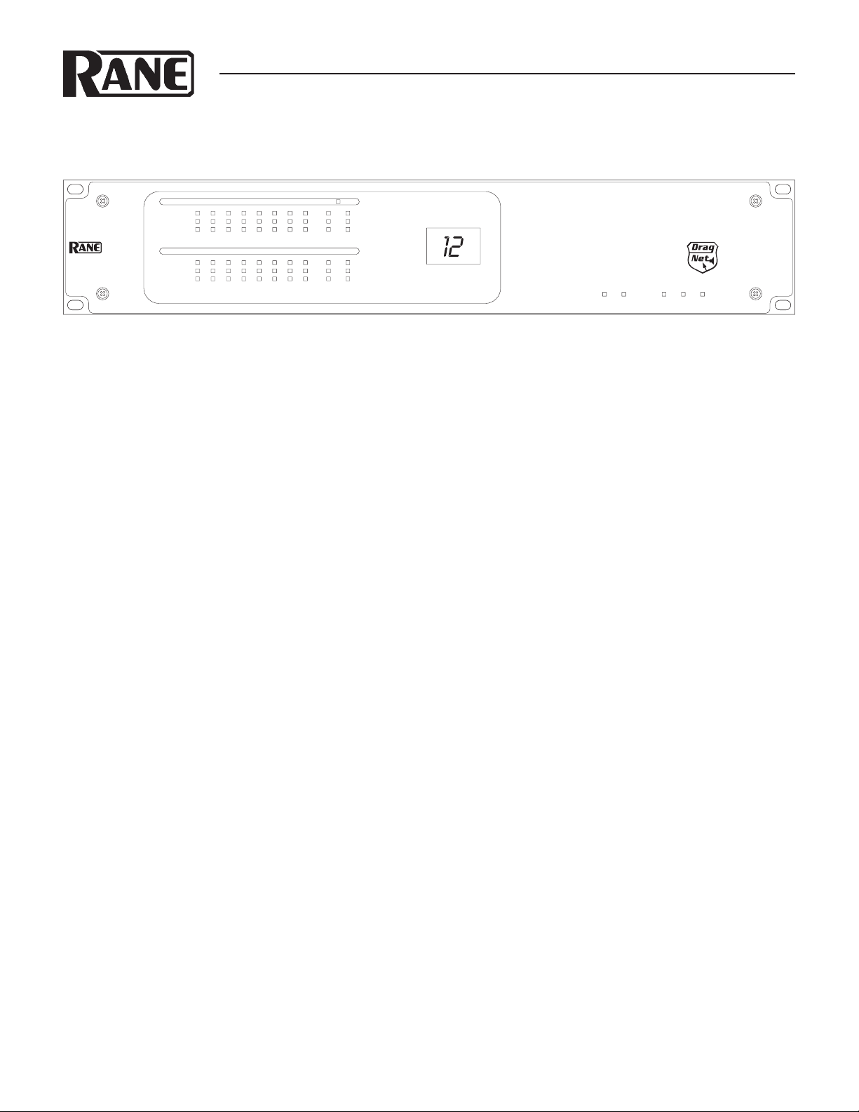
Front Panel Description
INPUT
12345678
-4
-12
-48
OUTPUT
12345678
-4
-12
-48
Peak dBFS
1 2 3 4 5 6 7 8
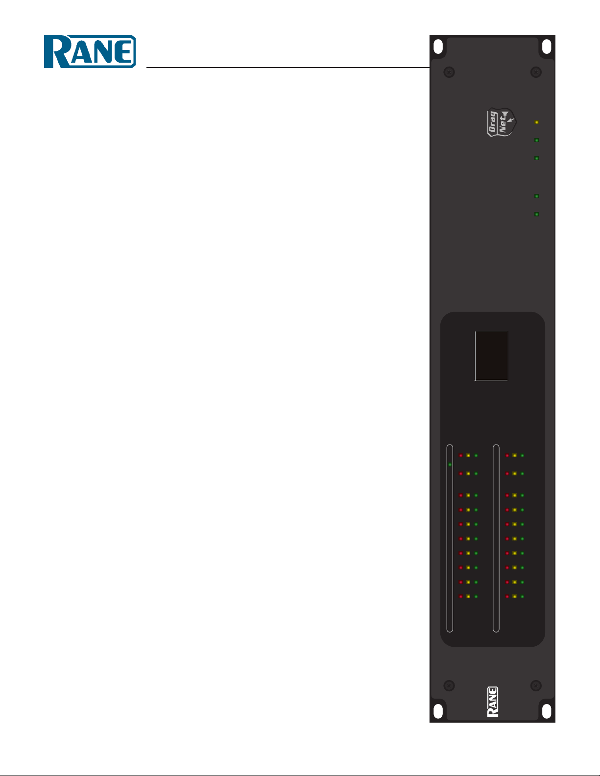
1 Signal/Overload LED meters indicate the presence of signicant audio signal or overload. ese 3-segment meters indicate the
available headroom once the analog signal has been converted to digital: -4 dBFS (red, near clipping), -12 dBFS (yellow, high
normal level), and -48 dBFS (green, low level). e analog signal level depends on the input and output settings and is displayed in
Drag Net’s Meter window.
2 AES3 LOCK LED lights solidly when a valid AES3 digital signal is detected on the AES3 input jack. ere does not need to be
an audio signal present at the input, only the “carrier” signal.
AES3
LOCK
AB
AES3
AB
-4
-12
-48
-4
-12
-48
PRESET
VIP/VOP RW 485
ETHERNET
STATUS POWER
RPM 88
PROGRAMMABLE
MULTIPROCESSOR
3 PRESET LED displays the number of the most recently recalled Preset, numbered 0 through 24.
4 VIP/ VOP LED ashes when a change is detected on the Versatile Input Port (VIP) or Versatile Output Port (VOP). ese ports
are used for direct electrical connections to potentiometers, switches or other logic ports. e Versatile Input Port accepts up to
eight contact closures or voltages; the Versatile Output Port drives eight loads (logic on/o).
5 RW 485 LED ashes when a change in setting is detected on the RW 485 Remote Interface Port. RW 485 is a serial communica-
tions protocol primarily used for Rane’s Smart Remotes.
6 ETHERNET LED ashes when an Ethernet data packet for this device is received.
7 STATUS LED reects the overall status of the unit:
Red - initializing (briey) or possible internal error.
Yellow - working, but not currently processing audio.
Green - processing audio.
8 POWER LED lights solidly when the unit is powered on.
Manual-2
Page 5

Rear Panel Description
23
COMMERCIAL AUDIO
EQUIPMENT 24TJ
R
OUTPUTS
REMOTE INTERFACE PORT
(RW 485)
A B +V -V
A B +V -V
43 21
+– +– +– +–
VERSATILE OUTPUT PORT
OPEN COLLECTOR
+40 VDC / 100 mA MAX
12345 76 8
12345 76 8
100-240V
RPM 88
MADE IN U.S.A.
RANE CORP.
ACN 001 345 482
FOR CONTINUED
GROUNDING
PROTECTION
DO NOT REMOVE
SCREW
55 WATTS50/60 Hz
87 65
+– +– +– +–
10Base-T
DEFAULT LAN
LINK
1 10 9 8 7 6
100 mA
MAX
+12
GND
+12
GND
87 65
+– +– +– +–
VERSATILE INPUT PORT
0-5V
12345 76 8
12345 76 8
REF
REF
+5v /
100 mA
GND
GND
INPUTS
43 21
+– +– +– +–+– +– +– +–+– +– +– +–+– +– +– +–
+– +– +– +–
This device complies with Part 15
of the FCC Rules. Operation is
subject to the following two
conditions: (1) this device may not
cause harmful interference, and
(2) this device must accept any
interference received, including
interference that may cause
undesired operation.
AES3 OUT AES3 IN
45
1 POWER IEC jack connects to AC line voltage, 100-240 VAC ±10%.
2 Balanced analog audio Inputs 1 through 8. Euroblock connectors.
3 Balanced analog audio Outputs 1 through 8. Euroblock connectors.
4 AES3 digital audio Input and Output. XLR female (input) and male (output) connectors.
5 Versatile Input Port provides 8 logic or voltage inputs for remote level control and Preset recall. Euroblock connector.
6 Versatile Output Port provides 8 logic outputs capable of driving small relays, LEDs or other logic inputs. Euroblock connector.
7 RW 485 Port communicates with Rane’s Smart Remotes. A maximum of 280 mA of current is available for powering remotes.
Euroblock connector.
8 LAN and LINK reect the state of the Ethernet connection. LINK lights solidly when a valid connection to another Ethernet
device (e.g., a PC) is detected. LAN ashes when communicating with another Ethernet device.
9 10Base-T jack accepts a standard Ethernet cable. RJ-45 connector.
0 DEFAULT button recalls Preset 1 when pressed. Holding this button while applying power puts the unit into a special codeload
mode for updating rmware. e letters “CL” appear on the PRESET LED display when the device is in codeload mode.
Manual-3
Page 6

Audio Connections
As a safety precaution, turn all devices (especially power ampliers) OFF when making connections. Doing so gives you a chance
to nd and correct wiring mistakes and prevent damage to your
ampliers, speakers, ears, etc.
Analog Inputs and Outputs
e RPM 88 has eight balanced analog Inputs and eight balanced analog Outputs.
For each Input or Output Euroblock connector:
• Connect the (positive) audio line to the ‘+’ terminal.
• Connect the (negative) audio line to the ‘–’ terminal.
• Connect the cable shield to the ground terminal.
For those installations where the RPM 88’s internal shieldto-chassis connection causes interference, connect each shield
directly to the chassis PEM nut located above each Euroblock
connector, keeping the shield wrapped around the audio conductors as much as possible.
For optimum Electromagnetic Interference (EMI) immunity,
connect the shields at both ends of the cable. See the RaneNote
“Sound System Interconnection” for more information on system
connections and proper grounding practices.
Analog Input Stage
Each analog input uses a two-stage gain approach. e rst stage
contains a software controlled analog line/mic pad and switchable-gain preamp. e second stage contains a Digital Trim
control located immediately after the A/D converter.
Analog Output Stage
Each analog output also uses a two-stage gain approach, which
diers slightly from that of the analog input stage. e rst stage
is a Digital Trim control located immediately before the D/A
converter. e second stage is an analog trim control located immediately after the D/A converter. Attenuation is handled in the
analog domain, while boosting (when the incoming digital signal
is low) is handled in the digital domain. Boosting and attenuating using this two-stage approach helps maintain the RPM 88’s
excellent noise performance.
Digital (AES3) Input and Output
AES3 is a popular 2-channel (stereo) digital audio interface commonly found on professional digital audio equipment (digital
mixers, DAT machines, etc.). Each channel of the AES3 digital
stream is treated independently within the RPM 88.
See the RaneNote “Interfacing AES3 and S/PDIF”, available
from Rane’s web site (www.rane.com/library.html), for more
information about interfacing consumer S/PDIF gear to the
professional AES3 standard.
Use the AES3 I/O to:
• Connect multiple RPM 88s together to create a 2-channel
digital “bus” between devices.
• Connect directly to the AES3 output of a digital mixing
console.
• Connect directly to the AES3 input of a digital recorder.
• Connect to an external A/D or D/A converter, eectively add-
ing two more analog inputs or outputs.
Input Clipping
If you’ve set the Analog Gain so the input stage is not clipping,
it is not possible to clip the A/D converter, since there is no additional gain between the initial input stage and the A/D converter. e Digital Trim control, located after the A/D converter, can
be set to clip the signal to your heart’s content, so adjusting this
trim to provide the hottest signal to the DSPs without clipping is
the most important step when setting up gain structure. For this
reason, a dedicated meter displaying the signal level being passed
to the DSPs is provided in each Analog Input block.
If the DSPs are working with a clipped signal, the audio is (as
expected) distorted and none too pretty, but it is not a drastic,
damaging sound. And while it’s technically possible to write a
DSP algorithm to emulate the glorious clipping distortion of
vacuum tubes, it’s not particularly useful for an installed sound
system, where the DSP power could be put to better use removing that annoying 500 Hz feedback from the Pope’s podium mic.
Plus, they don’t yet make DSP chips with gold-plated substrates
for those fecund highs and that moist, supple midrange.
Incoming Sample Rate and Word Length
e AES3 input has a built-in sample rate converter capable of
accepting incoming sample rates up to 96 kHz. Sample rates exceeding the RPM 88’s internal 48 kHz sample rate are automatically downsampled. Word lengths up to 24-bits are accepted.
Outgoing Sample Rate and Word Length
e AES3 output uses a xed 48 kHz sample rate and 24-bit
word length.
Control Connections
Versatile Input Port (VIP)
Eight logic input pins are provided, each capable of accepting DC voltage between 0 and 5 volts. VIP pins are used with
contact closure switches for Preset recall, or with potentiometers
for remote Level control. e functionality (Preset recall versus
control) of each pin is assignable as part of the Device Conguration.
• e maximum allowable voltage on any VIP pin is 5.3 VDC.
• Use of twisted pair cable is recommended for better noise
immunity.
• If an external device is used to generate a 0 to 5 volt signal,
connect the ground of the external device to the GND pin of
the V IP.
Manual-4
Page 7

Preset Recall Using Contact Closure Switches
VIP CONNECTION
VOP CONNECTION
e minimum “low” voltage required to detect a contact closure
and change Presets is 2.5 V. Since the internal pull up is 100 kΩ
to +5 V, it is possible to calculate the maximum allowable cable
length, provided the wire resistance per foot (or meter) is known.
Example:
To be safe, let’s allow a maximum of 80 kΩ worth of cable
resistance. is value keeps the voltage divider formed by the
100 kΩ internal resistance and 80 kΩ cable resistance from
dropping below 2.5 V.
(5 V * 100 kΩ) / (100 kΩ + 80 kΩ) = 2.777 V
If the cable resistance is 30 Ω per 1,000 feet
(1,000 feet / 30 Ω) * 80,000 Ω = 2,666,666 feet.
us, you can only use 2,666,666 feet (505 miles) of twisted
pair cable before the Preset recall functionality becomes intermittent (assuming the cable is properly twisted and not run
through excessive magnetic or electric elds).
Remote Level Control Using Potentiometers
e VIP inherently prefers linear taper 10 kΩ potentiometers,
which provide a nice audio taper “feel” for the end user. When
used with suitable twisted pair wiring, the 10 kΩ value also offers acceptable noise immunity and very long cable lengths.
Versatile Output Port (VOP)
Eight open collector logic output pins are provided, each capable
of sinking 100 mA of current. e on-board REF voltage of
12 VDC provides a maximum of 200 mA of current. Use an
external power supply (40 VDC maximum) if more current is
required, but be sure to connect the external supply’s ground to
the GND pin on the VOP.
RW 485 Port
e RW 485 port uses a simple, proprietary protocol to communicate with Rane’s optional Smart Remotes (SR 2, SR 3, SR 4).
e details of this protocol are found in each of the SR Manuals,
available from Rane’s website.
is port follows the electrical specication found in the
TIA/EIA-485 standard, with one exception: the recommended
termination impedance is neither implemented nor required,
since RW 485 uses a relatively slow baud rate (38,400 bps). In
(examples for VIP pin 1)
pin 1
GND
Contact
Closure
REF
pin 1
GND
Potentiometer
Level Control
20 kΩ (linear)
fact, including the termination has proven to hinder the performance of the RW 485 bus.
Five connection terminals are provided: a balanced pair of
data lines (A and B), a pair of power lines (±V), and a chassis
ground. All terminals should be connected to the corresponding
terminals of the Smart Remotes.
Up to 8 remotes, each having a unique address, can be connected to the RPM 88. Any mix of SR 2, SR 3 and SR 4 remotes
is possible, as is any combination of star or daisy chain wiring
congurations.
e cable length limitations and the maximum number of
remotes that can be powered from the RPM 88 is limited by the
mix of remotes used, the cable type used, the distance to each remote, and the wiring conguration. Detailed wiring and cabling
tables and several examples are discussed in the SR Manuals. A
Microsoft Excel Cable Length Calculator is downloadable from
the Rane website (go to the SR product pages).
e RW 485 port provides up to 280 mA of current, used to
power connected remotes. Each SR 3 remote requires approximately 90 mA, thus up to three SR 3 remotes can be powered
directly from the RPM 88.
Additional remotes may be powered using an external supply
(8 to 15 VDC regulated, minimum 0.8 amperes), leaving the +V
terminal of the RPM 88’s RW 485 port disconnected.
e RW 485 port is intended to be used with Rane’s Smart
Remotes only; we do not recommend directly interfacing the
RW 485 port with devices that are not compliant with the TIA/
EIA-485 standard, such as the “485” ports found on AMX and
Crestron devices.
(examples for VOP pin 1)
100 mA coil
current max
+12
+12
2 kΩ
pin 1
Light an LED Relay Drive
NOTE: +12 VDC is available on the VOP. An external supply may be used as long as any VOP pin voltage never exeeds 40 VDC.
pin 1
1N4001
+12
pin 1
Examples shown are for 12 VDC only.
Crydom P/N D1225
4
3
Line Voltage Switching
1
2
24 to
140 VAC
25 A max
Manual-5
Page 8

AMX and Crestron Control
ere are two ways to control a Drag Net device from an AMX
or Crestron system. Use either Ethernet connectivity or use the
rear panel Versatile Input Port (VIP). Each of the 8 VIP pins
supports either switch closure Preset recall or zero-to-ve volt
control of Level.
e RW 485 ports found on some Drag Net devices do not
communicate with AMX or Crestron systems. ey are solely for
communicating with Rane's RW 485 remotes.
Many AMX/Crestron applications require simple Level control and/or Preset recall. is is most easily accomplished using
the VIP (Versatile Input Port) found on all ve Drag Net devices: RPM 2, RPM 26z, RPM 22, RPM 44 & RPM 88. ere
are always more Drag Net products coming — both hardware
and software, so check our home page for the most recent.
VIP Preset Recall
Connect a switch closure or relay to a VIP pin and short it to
the ground (GND) pin to recall the corresponding Preset. For
example, shorting VIP pin 1 to the GND terminal recalls Preset
1; pin 2 recalls Preset 2, etc. ere are more details about this
functionality in the Drag Net Help le and on our Drag Net Applications page. Be certain to appropriately set the VIP Allocation in Drag Net's Parameter Window.
If GND contention of two or more pins simultaneously
occurs, the highest-numbered VIP pin takes precedence. For
example, if pin 3 is shorted to GND and pin 6 is then shorted
to GND, Preset 6 is recalled. If pin 3 is closed and then pin 2,
nothing happens -- Preset 2 is not recalled. is permits a hierarchy of Presets when using VIP pin closures for tiered priority
paging. Since there are only eight VIP pins, you can only recall
up to eight Presets using switch closures.
ere are four ways to recall more than eight presets.
1. Use the Drag Net software Recall button which is only in-
tended for the system installer/designer.
2. Use the Rane SR 4 remote to recall any eight Presets.
3. Use a Rane SR 3 remote which can recall any 16 of the avail-
able 24 Presets.
4. Use an Ethernet command from an AMX or Crestron Ether-
net-equipped product.
[When using Drag Net's Auto Mixer/Ducker block, you have
the ability to link a VIP pin closure to a push-to-talk switch in a
paging or boardroom application. When using the Ducker block
in these applications, the VIP pins act independently provided
you Group the appropriate VIP pin with the Auto Mixer/Ducker's Input in Drag Net's Remote Map. Again, see our Drag Net
Applications for examples.]
VIP Level control
Connect a zero to ve volt DC voltage to a VIP pin from an
AMX or Crestron card to adjust any or all Level blocks placed in
the Processing Map. Use Groups in Drag Net's Remote Map to
link one or more Level blocks so they track each other when using a VIP pin. Be certain to appropriately set the VIP Allocation
in Drag Net's Parameter Window. When using VIP pins with
Level blocks, set the minimum and maximum for each Level
block by double-clicking it while it's in a Remote Map Group.
is keeps the max and min burdens within the Drag Net device
— but only when using the VIP pin to control Levels, not when
adjusting Levels from Ethernet commands.
You can use up to eight voltage control inputs linked to
Level(s) using the rear panel VIP pins. Combinations of Preset
switches & voltage Level “pots” are possible as long as combined,
they do not exceed the eight pins provided.
Since you can Group any or all Level blocks in Drag Net's
Remote Map, it's much easier to implement a stereo level control
since the Drag Net device is burdened with the task of tracking
many Levels. You can use this to your advantage when using VIP
pins to adjust multiple zones or levels. Since you can place the
Level block anywhere within the Drag Net Processing Map, you
can Group Level blocks at the input, at the output or anywhere
in-between — just place the Level block where you want it.
Ethernet control
Download the AMX or Crestron control code and documentation from the Drag Net web page: www.rane.com/dragnet
Ethernet Port
e Ethernet port is used to congure, monitor, and control
the RPM 88 via standard 10Base-T Ethernet communication.
Use an Ethernet crossover cable (one is included with each unit)
to connect the RPM 88 directly to a computer. Use a standard
(non-crossover) Ethernet cable if the RPM 88 and computer are
connected indirectly using an Ethernet repeater hub or switch.
All devices connected to the Ethernet port, including
repeater hubs, switches, and the computer’s Network Interface
Card (NIC) must support 10Base-T communication.
©Rane Corporation 10802 47th Ave. W., Mukilteo WA 98275-5098 USA TEL 425-355-6000 FAX 425-347-7757 WEB www.rane.com
Manual-6
108358
Page 9

Drag Net Quick Start
Rane’s tradition of writing a one page Quick Start section in our
manuals has been revamped. Since this section is four pages, it’s
called the Mostly Quick Start section.
Drag Net software installation is straight forward — just
run the setup.exe le included on the CD-ROM or downloaded
from Rane's website (www.rane.com/dragnet) and follow the on-
screen instructions.
You are prompted to create a new project and device conguration the rst time Drag Net is launched. Enter the project
name and le storage location on your hard drive. A second
dialog allows you to create a new device conguration. Select a
device type, RPM 26z for example, and specify a hard drive storage location to create a new conguration.
Once a new project and conguration have been created, a
collection of windows is displayed within the Drag Net interface.
ese windows can be independently resized, opened, closed,
docked and oated as you prefer.
• e Shortcuts folder displays a list of links to non-Drag
Net les or applications (e.g. project spreadsheets, proposal
documents), URLs, and even email recipients. Doubleclick on a Shortcut to open it using the associated application. Add additional links to the Shortcuts folder by rightclicking within the Project window and selecting New.
• e Live folder displays a list of “online” Drag Net devices.
Click on the Poll icon or right-click in the Project window
and select Poll for devices, then choose one of the polling
options. e Live folder is populated as the polling operation progresses.
Transfer congurations between Storage and Live by dragging and
dropping congurations from one folder to another, or by using the
Transfer menu.
All outputs are intentionally muted each time a new conguration is transferred to a Live device. Unmute each output individually or use the Mute Outputs button in the toolbar to toggle the mute
status of all outputs (after carefully pondering the consequences, of
course).
e Project Window is comprised of three folders and provides
links to Storage congurations, Shortcut links to other les or
applications, and a list of Live devices. ink of a Project as an
editable database of links — only the links to les are contained
in the Project le (*.prj le extension). e Project le neither
stores nor contains any of the settings for a particular device
conguration, it just consolidates and manages links to the relevant les (for examples, the RPM 26z congurations are stored
with a .r26 le extension, and the RPM 88 congurations have a
.r88 extension). Changes to a Project's contents are automatically
saved. Only one Project at a time can be viewed in the Project
window.
• e Storage folder displays a list of “oine” or Storage
congurations residing on the local hard drive. Add links
to new or existing congurations to the Storage folder by
right-clicking within the Project window and selecting
either New or Add le(s).
e Device Conguration Window displays the current device
conguration, activated by double-clicking a Storage or Live
conguration (or alternately by right-clicking and selecting Open
Item). It is comprised of two distinct views: the Processing Map
and the Remote Map. Toggle between views using the tabs at the
bottom of the window. e Processing Map serves two basic
functions:
• It allows drag and drop techniques to assemble and connect
any combination of signal processing blocks between the inputs and outputs of a Storage conguration. It is not possible
to add or delete signal processing blocks or connections on a
Live conguration.
• It allows you to view and edit, in real-time, all signal process-
ing parameters for Storage or Live congurations. Doubleclick the processing block or right-click and select Properties
to display a Properties (parameters) dialog. Changes made to a
Live conguration are automatically transferred to and saved
in the Live device. Changes made to a Storage conguration
must be saved using the Save command.
Drag Net Quick Start-1
Page 10

e Remote Map is used to congure the Versatile Input Port
(VIP) and the RW-485 Remote Interface Port, if the RPM unit
is so equipped. e VIP accepts either contact closure switches
for Preset recall, or 0-5V potentiometer-on-a-wall devices for
Level control. Double-click Edit VIP Properties in the Parameter
Window to allocate multi-pin or single-pin control. Multi-pin
control is used with contact closure switches to recall Presets,
or to select inputs in a Source Selector, for example. Single-pin
control is used for independent parameter control: to adjust levels
using a potentiometer, or to engage the Push-to-Talk function of
an Auto-Mixer input, as examples. See the “Using the Remote
Map” section of Drag Net’s Help (Help > Help Topics) for the
full scoop.
e Remote Interface Port uses Rane's RW 485 protocol to
communicate with our SR series of Smart Remotes. Double-click
Add/Edit Remotes in the Paremeter window and follow the onscreen instructions to add new Remotes or edit existing Remotes.
Smart Remotes can perform many functions including Preset
Recall, Source Selection, and Level control. See the “Using the
Remote Map” section of Drag Net’s Help (Help > Help Topics)
for more information.
e Preset Window manages the creation and storage of Presets.
A Preset may contain any or all of the processing and control
blocks displayed in the Device Conguration window. Add
blocks to the Preset block list by dragging and dropping them
from the Device Conguration window to the Preset window,
or by right-clicking the block and
selecting Add to preset. Remove
blocks from the Preset window by
selecting one or more blocks from
the list, then using the Delete key
or the Remove Selected Block(s)
button. Click the Store button and
select a Preset number to store the
current settings of all blocks contained in the Preset block list.
Presets are recalled using
the Recall Presets button in the
toolbar at the top of the screen.
When a Preset is recalled, only the
parameters or Remote Map associations of the blocks contained
in the Preset change; all other
blocks maintain their current settings, thereby creating a parameter
overlay eect. e Preset window
does not have to be visible in order
to recall Presets.
e Palette Window displays
the audio processing blocks used
to create Storage congurations.
Drag and drop blocks from the
Palette to the Device Conguration window to develop your
audio system. e various tabs
(Dynamics, Mix, etc.) are used to
sort the Palette window by block
class. Select the All tab to display
all available blocks.
Drag Net Quick Start-2
Page 11

e Resource Window displays usage information specic to
the hardware device you're working with. e DSP usage meter
indicates the amount of DSP "horsepower" used by the current
conguration, and is always accurate. ere is no need to hit a
“compile” button, since Drag Net automatically compiles on the
y as you work. It is possible to exceed 100% DSP usage when
developing Storage congurations, but it is not possible to transfer the Storage conguration to a Live device. e Delay blocks
meter indicates the amount of audio delay memory used in the
current conguration. Audio delay memory diers from memory
used by other signal processing functions; thus, it is given its
own meter.
Propagation delay (latency) statistics for both the analog
I/O and the AES3 digital Input are also displayed in the Resource window. e propagation delay varies slightly with the
quantity of signal processing blocks used in the conguration.
Importantly, the propagation delay for all analog I/O is forced to
be the same (referred to as “Delay Compensation”), in order to
maintain the relative timing between input signals (unless you
add a Delay block to the signal path, of course).
e Meter Window provides two tabbed views of all input and
output levels of a Live device. e Analog tab shows the calculated level, in dBu, at each analog input and output.
e Converters tab displays the dB Full Scale (dBFS) reading immediately after the input A/D converters and immediately
before the output D/A converters. e AES3 digital input meter
(dBFS) is displayed in both views.
e number of meters provided varies with device type. Meters are only active when working with a Live device.
e Parameter Window displays a tree structure view of all
signal processing and control blocks used in the active Device
Conguration. It is organized by block type (Input, Output,
Dynamics, Filter, etc.), with individual parameters appearing as
sub-entries beneath each block entry.
Individual parameters within a block are prefaced with “##”.
e Parameter window is primarily used to set up associations between parameters and remote control devices (VIP pins,
Smart Remotes).
Other things you can do with the Parameter window:
• Double-click any entry to view its Properties dialog.
• Drag-and drop entries from the Parameter window into the
Preset window to quickly build Presets.
• Edit VIP Properties.
• Add or Edit RW 485 Smart Remotes.
• Edit VOP Properties.
Handy tip: e Parameter window supports multi-select operations. Simply ctrl-click or shift-click multiple entries to perform
the same action for the entire selection – add a range of blocks to
the Preset window, for example. Alternately, you can select a top
level block – the Input block, for example – and perform actions
on all related sub-entries.
Drag Net Quick Start-3
Page 12

Big Picture Concepts
Storage Mode versus Live Mode
When you rst create a Drag Net device conguration, it is
stored and appears under the Storage folder of the Project Window. ink of this as oine mode. Any changes made to Storage
conguration are saved to your computer only; they are not
updated automatically on the Live device.
Storage congurations are transferred to a Live device, which
appears under the Live folder of the Project window after successfully polling for devices.
After transferring the conguration from Storage to Live you
can adjust parameters, build Presets, and set up Remote Map
associations in real time on the Live device. You can not add/delete blocks or wires. ink of this as online mode. All changes
are automatically saved to the Live device; however, periodically
transfer the Live device settings back to a new or existing Storage
conguration in order to maintain an oine (backup) copy of
system settings. Live device settings are not automatically kept in
synch with Storage congurations.
File Concepts
A Storage conguration consists of:
• e Processing Map (schematic/audio signal ow).
• Parameter settings (gains, delay, EQ, etc.) and Preset info.
• Remote Map link info.
In Drag Net 4.2 and higher, these items are stored in a single
conguration le (see Project Window on page 1). is makes it
easier to track, transfer between computers or email your Drag
Net congurations. Previous to 4.2, this data was in three independent les.
Dragging Tips (Storage mode)
Audio ow: Drag and drop blocks from the Palette window
to the Processing Map to build the audio portion of a Device
Conguration.
Control: Drag and drop items from the Parameter window
to the Remote Map to build the control portion of a Device
Conguration.
Move blocks around the Device Conguration window by
left-clicking the block to select it, then dragging the block to a
new location while continuing to hold down the mouse button.
Alternately, left-click the block to select it, hold down the CTRL
key, then use the arrow keys to reposition the block.
Drag and drop blocks from the Device Conguration window to the Preset window to add blocks to the Preset block list.
Drag and drop congurations between the Storage and Live
folders in the Project window to transfer congurations between
the PC and a Live unit.
Wiring Tips (Storage mode)
Wires can be dragged from Out pins to In pins found on each
processing block. A couple tips:
• You must wire from an Out pin to an In pin.
• Any Out pin can be wired to as many In pins as desired
— a dedicated split block is not required. It is not possible,
however, to connect multiple Out pins to a single In pin. Use
mixers or selectors for this purpose.
Presets
e current settings of a device (all Properties, or parameters) are
always stored in working memory and displayed in the Device
Conguration window, making for a true WYSIWYG (What
You See Is What You Get) interface. Each user-denable Preset
can store processing block Properties and Remote Map settings
for subsequent recall. A Preset can be comprised of any or all
processing or control elements displayed in the Device Conguration window.
Only the processing parameters and the Remote Map set-
tings are stored in Presets — it is not possible to change the wire
routing or signal ow using Presets. If you require a completely
new signal ow, you must either draw all required parts of the
system in the Processing Map and then toggle Presets to route
the audio between the various system blocks using selectors or
mixers, or transfer a new Storage conguration from the PC to
the Live device.
Storing to Presets
Click the Add All Blocks button, located next to the Store
Preset button in the Preset window, to populate the Preset block
list (Name/Type) with all blocks on the Processing Map. Store a
Preset by clicking the Store Preset button and selecting a Preset
number. e current settings of each block in the list are stored,
the device conguration is automatically saved, and the stored
Preset is automatically recalled.
It is also possible to store and recall a subset of processing
and control blocks. Drag and drop (or alternately right-click a
block and choose Add to Preset) only the blocks you want stored
in the Preset from the Device Conguration window to the
Preset window. When the Preset is recalled, only the settings of
the blocks contained in the Preset are modied; all other blocks
remain unchanged from their current state. us, recalling
the Preset “overlays” the current settings with a subset of new
parameters.
Recalling Presets
e Recall Preset button in the toolbar at the top of the screen
recalls previously stored Presets. When a Preset is recalled, its
number is displayed in the upper right corner of the Preset window, the block list in the Preset window is populated, and small
numbered tags appear in the lower right corner of each processing or control block comprising the recalled Preset. Clear these
tags by right-clicking within the Device Conguration window
and selecting Clear all preset tags.
©Rane Corporation 10802 47th Ave. W., Mukilteo WA 98275-5098 USA TEL 425-355-6000 FAX 425-347-7757 WEB www.rane.com
Drag Net Quick Start-4
106 405
 Loading...