

Page 1

OPERATORS MANUAL RPM 26
DSP MULTIPROCESSOR
QUICK START
If you don’t read all of this document, you risk setting up your system improperly. But at least read this section and the
Input Trim section on page Manual-12. Paying careful attention to your system’s gain structure and setting the RPM’s
Input Trim properly are essential in maximizing the noise performance of your entire system. (See the enclosed RaneNote
“Setting Sound System Level Controls”.) Once you’re done reading and memorizing the manual, please recycle the paper
it is printed on by reconing an old speaker. If RaneWare has not yet been installed on your computer, refer to STEP BY
STEP RANEWARE INSTALLATION on page Manual-2 first.
Leave the audio connections on the RPM 26 until last. Connect the RW 232 INPUT jack on the unit’s rear to a serial
(COM) port on a PC-compatible computer using a standard 9-pin RS-232 cable. A short one is supplied with the unit,
which is intended to connect between units in a rack. The cable and adapter must not be a null-modem type.
Locate the RW 232 DEVICE ADDRESS switch on the rear panel. If this unit is to be used by itself, set the switch to
‘1’ by setting all switches off (down), except switch one (labeled ‘1’ on the chassis, the right-most switch when viewed
from the rear). If there is more than one unit, refer to Device Address Calculator in the software’s Help system or run
the included Device Address Calculator software and set a unique address for each unit.
Apply power by connecting the RS 3 remote supply’s 5-pin DIN jack to the rear of the unit, then connect the IEC end
to a powered AC outlet. CAUTION: Do not connect anything but an approved RANE power supply to this jack. If the RS 3
and the RPM 26 are getting power, the yellow front panel POWER LED will be on.
Start your computer, run Windows®, and launch RaneWare by double-clicking on the RaneWare™ umbrella icon.
(See the next page for software installation instructions.) The Help file’s Software License Agreement appears the first
time RaneWare is run — read it all and close it. Then the System Setup window may appear. If it doesn’t, select
System Setup from the Setup menu. Be careful to select the COM port which is physically connected to the RPM 26.
Click OK. Now, the Device Selection window may appear. If it doesn’t, choose Select from the Device menu. Click on
Poll… and the Devices Found: displays the units found. Click the Stop button to stop Polling. Select the unit from the
Device Selection window and click OK. If no unit was found, please refer to the TROUBLESHOOTING section at the
end of this manual or in the software’s Help system.
Several clues indicate communication between the computer and the RPM 26. The yellow COM (communications)
LED on the front of the unit flashes or stays on. The Memory numbers (1-16) near the top of the computer screen will be
black rather than gray. The Active indicator at the bottom left of the computer screen will be green.
Important Note: The RPM 26 contains many insightful, preprogrammed DSP Programs. Each “fixed” DSP Program
can be thought of as a unique “system setup,” i.e., 2-way crossover system, 3-way system, 2 x 6 splitter, etc. Each of the 16
Memories can contain a different DSP Program. Before connecting the RPM 26 to the other audio components in your
system, it is wise to choose and store the appropriate DSP Program for your system in all 16 Memories. This avoids the
problem of accidentally recalling a Memory that restores an undesired DSP Program, such as the case where you recall
from a 3-way DSP Program to a splitter: this sends full-range audio to all Outputs!
Once the proper DSP Program is stored in the RPM’s memories, audio connections can be made. Turn the amplifier(s)
off until all connections are complete. Connect balanced audio INPUTS and OUTPUTS to the Euroblocks on the rear.
SYSTEM REQUIREMENTS
RaneWare works under Microsoft Windows 3.1 or
Windows 95®, on a PC or laptop with an unused serial port.
Recommended optimum system: 486 or higher with at least
16 colors. Monochrome displays work, though adjustment of
the gray scaling is necessary for optimum viewing.
RW 232, RaneWare’s protocol, uses a DB-9 cable less
than 50 feet long, connecting from the serial port of a computer to the RPM 26 communications Input port. No interface
boxes are required; just a cable and your computer.
RaneWare can be fully demonstrated and used without an
actual RPM 26 attached. Simply select the OFFLINE
RPM 26 or any other OFFLINE unit under Select in the
Device menu.
Windows is a registered trademark of Microsoft Corporation. RaneWare is a registered trademark of Rane Corporation.
A RaneWare 3½" floppy comes with each unit. Installation is simple, using the instructions below. The latest version
is downloadable 24 hours a day from Rane’s Internet site:
http://www.rane.com.
Note: If you have previously
installed an older version of
RaneWare and you just received a
new RPM 26 unit, you must reinstall
the new version of RaneWare that
was shipped with your unit. Use of
an old version will not work and
could be a leading cause of halitosis.
Manual-1
Page 2

FRONT PANEL DESCRIPTION
1. Signal/Overload. These multi-color LEDs indicate the presence of a significant audio Signal (green) or Overload conditions
(red). Both Input and Output indicators are provided for signal flow verification without a computer. The Inputs’ Signal
LEDs are driven from an analog comparator circuit prior to the input level control. All other LEDs are controlled from the
microprocessor.
The Output LEDs cycle yellow from left to right during power up and when the unit is loading a new DSP Program. All
outputs are muted during DSP Program changes.
If Output 1 or 2 is flashing, something has gone wrong. See TROUBLESHOOTING on page Manual-21.
2. COM (yellow, communications) flashes when a message for the unit is successfully received. This LED flashes often when
communicating with the computer, since metering messages are continually requested by the computer. The COM LED may
flash so often it may appear to be constantly on. There is also a brief flash whenever the Remote Switch Interface is used.
3. POWER indicates that the unit is connected to a powered RS 3 remote supply.
RPM 26 CONNECTION
When connecting the RPM 26 in your system, leave its
power supply and the amplifiers for last. This gives you a
chance to correct mistakes before damage is done to your
amps, speakers, ears, etc. Also, be sure to read the Important
Note in the QUICK START section on page Manual-1.
The RPM 26 has balanced Inputs and Outputs, with
shields connected to the chassis through three #4 serrated
screws on the rear. Keep these screws tight for the best
possible shield-to-chassis connections. The RS-232 cable
shields connect to the chassis through the four nuts and star
washers that the cable screws into. Be sure to screw down RS232 cables to guarantee good shield connections. The chassis
and the audio signal ground are connected together internally at the audio Input screw terminal. The RPM 26 chassis
connects through the RS 3 power supply cables to the earth
ground (3rd pin) of the 100 and 120 VAC line cords. A 6-32
screw and star washer are also provided on the unit’s rear if a
technical ground connection is needed. This chassis connection is also recommended for 230V operation. Connect the
non-inverting (positive) audio lines to the ‘+’ terminals, and
the inverting (negative) lines to the ‘–’ terminals. Connect the
cable shields to the center terminal on the Euroblock. For
those installations where the RPM’s internal shield-to-chassis
connection causes interference, connect the shields directly to
the chassis PEM nuts directly above each shield terminal. Be
sure to bite through the paint with the star washer and keep
the shields wrapped around the audio conductors as much as
possible. For the “theoretical” best ElectroMagnetic Interference (EMI) immunity, connect the shields at both ends of the
cables. (For more information on System Connections, see
RaneNote 110, “Sound System Interconnection” later in this
manual or on Rane’s Internet Web site at www.rane.com.)
For those systems where Murphy and his EMI pests have
arisen or for those who wish not to tempt fate, the RPM 26
accepts optional line level input isolation transformers (Rane
part number 150-010). Call your nearest Rane dealer for more
information on the optional transformers.
To control the unit from a computer, use 9-pin RS-232
cables which are 50 feet or shorter. The cable and adapter
must not be a null-modem type. A short cable is supplied for
connecting adjacent units. Daisy-chain up to 250 units by
connecting the computer COM port to the RW 232 INPUT
connector on the first unit. Then connect the unit’s RW 232
OUTPUT connector to the next unit’s RW 232 INPUT.
The DEVICE ADDRESS switch identifies each unit with
an ‘address’, and must be set uniquely for each unit. The
switches form a binary code from 0 through 255. Only the
numbers 1 through 250 may be used. The place values of
each switch are marked on the rear panel. The switch itself
may have numbers printed on it; these should be ignored. To
set a specific address, refer to the SETTING THE DEVICE
ADDRESS section on page Manual-22 or run the Address
Calculator software included with RaneWare.
The REMOTE SWITCH INTERFACE (RSI) provides
contact closure control for up to eight preset memories. No
computer is required after the initial setup. There are nine
screw terminals; one is the common chassis ground (COM),
and the other eight are for Memories 1 through 8. Connection
of one of these to the COM terminal causes the unit to recall a
preset Memory. Multiple units may be controlled by connecting these terminals in parallel. Either momentary or latching
switches may be used. A latching switch should only close
one contact at a time. If an RSI switch configuration changes
while the power is off, Memory recall results upon power-up
— since the RPM checks for changes to the RSI port each
time power is restored.
Manual-2
Page 3
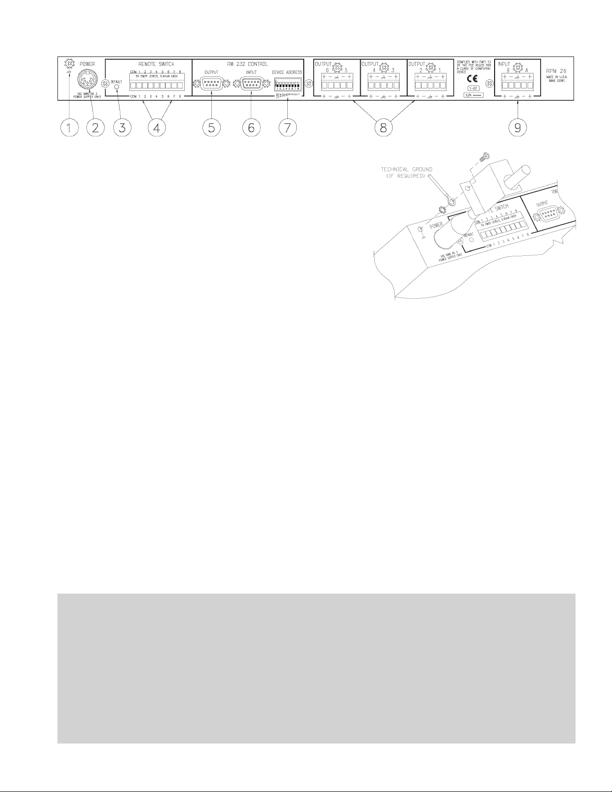
REAR PANEL DESCRIPTION
1. Chassis Ground Point This 6-32 screw and star washer have
three purposes:
A. Chassis ground when needed. The RPM 26 chassis connects through
the RS 3 power supply cables to earth ground (3rd pin) of the 100V
and 120V AC line cord.
B. It can also provide a technical ground connection if needed, (highly
recommended for 230V use).
C. It is also the attachment point for the RS 3 captivation bracket. (See
#2 below.)
2. Remote POWER jack is for connection to a Rane RS 3 power supply.
A. With the AC power disconnected, insert the RS 3 DIN plug into this
jack.
B. Attach the included RS 3 captivation bracket to the Chassis Ground
Point (#1 above). Install the star washer between the bracket and
the Chassis (especially if you are using this point as a technical
ground). The star washer helps guarantee a reliable electrical connection to the RPM 26’s chassis metal by biting through the non-conductive paint.
C. Now the unit is ready for AC power. To power the RPM 26 up and down, it is wiser to cycle the AC power cord, rather
than to unplug and plug the DIN jack.
3. DEFAULT switch recalls Memory 1. This may be useful in case of computer failure and duplicates the function of the
number ‘1’ Remote Memory Switch—without the need for an external switch (See Signal/Overload on page Manual-2).
4. REMOTE SWITCH INTERFACE (RSI) provides the ability to recall one of 8 Memories using contact closures. The
front panel COM LED flashes briefly whenever the RSI switch configuration changes. Since each memory can contain a
different DSP Program (i.e., a 2-way crossover in one memory, 3-way in another), in a fixed installation, be sure that all
memories contain the appropriate DSP Programs for your system. This avoids the problem of accidentally recalling a
memory which could be detrimental to the system. On the other hand, this feature is useful in rental systems, for example,
where fixed DSP Programs can be stored in various memories requiring only an RSI wiring alteration to change the signal
processing from a 2-way to a 3-way system.
5. RW 232 OUTPUT connects to the RW 232 INPUT on other Rane RW 232 units.
6. RW 232 INPUT connects to the computer’s COM port, or to the RW 232 OUTPUT of the previous Rane RW 232 unit.
7. RW 232 DEVICE ADDRESS identifies each unit uniquely by assigning it a number from 1 to 250. Refer to the Device
Address Table on page Manual-22 or the RaneWare Address Calculator software for binary switch positions.
8. Balanced Outputs. No surprises here. Connect balanced audio connections as in RPM 26 CONNECTION on the previous
page.
9. Balanced Inputs. Connect balanced audio connections per the RPM 26 CONNECTION section on the previous page.
FCC NOTICE
This equipment has been tested and found to comply
with the limits for a Class B digital device, pursuant to Part
15 of the FCC Rules. These limits are designed to provide
reasonable protection against harmful interference when the
equipment is operated in a commercial environment. This
equipment generates, uses, and can radiate radio frequency
energy, and if not installed and used in accordance with the
instruction manual, may cause harmful interference to radio
communications. Operation of the equipment in a residential area is likely to cause harmful interference in which
case the user will be required to correct the interference at
their own expense. Changes or modifications not expressly
approved by Rane Corporation could void the user’s
authority to operate the equipment.
CANADIAN EMC NOTICE
This Class B digital apparatus meets all requirements of
the Canadian Interference-Causing Equipment Regulations.
Cet Appariel numerique de la classe B respecte toutes les
exigences du Reglement sur le material broilleur du Canada.
Manual-3
Page 4
STEP BY STEP RANEWARE INSTALLATION
1. If you have the RaneWare 3.5" floppy disk, insert it in your drive.
2. In Windows 3.1 Program Manager, under File, select Run.... On the Command Line:, type A:\install. (Use the drive
letter that matches your 3.5" drive, some systems use B: instead.) Click OK. Installation begins.
3. In Windows 95, from the Start menu, select Run.... Under Open:, type A:\install. Click OK. This starts installation.
4. If you downloaded RaneWare from the web, decompress the RaneWare .zip file first. Locate the now uncompressed
install.exe file and run it. Installation proceeds.
SOFTWARE OPERATION
STARTING RANEWARE
If RaneWare has not yet been installed on your computer,
refer to STEP BY STEP RANEWARE INSTALLATION
above. Once the software is installed, a RaneWare Program
Group is created with four icons. One icon each for the
RaneWare application, Help, Address Calculator, and
Manual. The RaneWare umbrella icon launches device
control, Help provides extensive on-line assistance, the
Address Calculator software makes selecting RW 232
device addresses easy and the Manual icon contains the
manual for the RPM 26 and the other RW232 products.
When the Device Control software is first run,
RaneWare’s Help screen displays Rane’s Software License
Agreement. The License Agreement is contained in the Help
file, so you can continue to browse for helpful details before
continuing. Once you’ve read the License Agreement, close
the Help file. After you’ve selected a Com port, subsequent
activations do not bring up the Help screen unless you ask for
it. Now let’s get on with the program. Double-click the
RaneWare umbrella icon.
Welcome to RaneWare! A splash screen displays for a
few seconds, then the Device Select window or an RW 232
Device Edit screen appears. To try the software without a
unit hooked up, select the OFFLINE RPM 26 and click OK
or to control a real RPM, click Poll, and polling for units
begins. This process checks if any units are connected to the
serial port. If a Device is found, you are in control! If you
have a device hooked up and it is not found, read the
TROUBLESHOOTING section on page Manual-21 or see
the Help file.
There are multiple RaneWare products available from the
RaneWare software screen. They include the RPM 26, the
RPE 228, a 2-channel, one-third octave equalizer, and the
ECS line of Engineered Conference Systems products for
teleconferencing and distance learning applications.
RW 232 BASICS OVERVIEW
All RW 232 devices, including the RPM 26, contain a
“current” or working memory (memory zero) and 16 additional memories where the current settings may be stored and
recalled. All of these memories exist inside the device, not
inside the computer controlling the device. Thus, if the
computer crashes, the unit continues to operate and keeps its
current settings. If the unit loses power, all current settings
are saved and automatically recalled upon power up — unless
an RSI contact switch has changed positions while the power
was off, then it recalls the selected RSI memory.
The Windows screens perform the traditional function of
a front panel, displaying and editing the device’s settings. For
example, the Store button tells the unit to copy its current
settings (Memory zero) into a specific memory number (let’s
say, Memory 4).
Use the RaneWare Button Bar to store and recall memories. (See THE RANEWARE BUTTON BAR section on page
Manual-10 for more details.)
Devices can also be given custom names, tailored to your
installation. Simply choose Name Device from the Device
menu (see page Manual-9).
If your installation changes by adding more units, choose
Device|Select, and the POLL button to make the computer
recognize new units in the system.
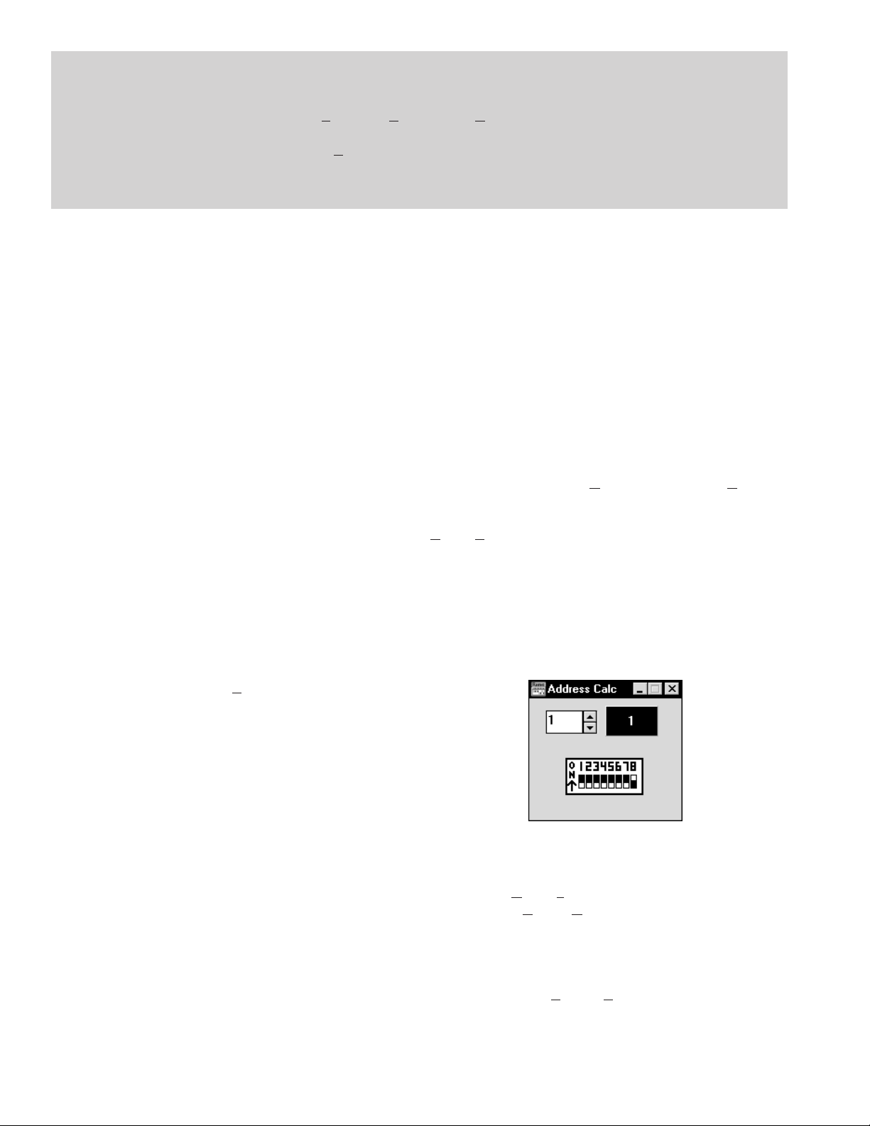
When multiple units are connected, assign each unit a
unique Device Address number. Rane provides a special
calculator to assist in setting the DIP switches on the back of
each unit. In the RaneWare Program Group, launch the
RaneWare Address Calculator. This binary calculator
converts decimal numbers into corresponding DIP switch
settings and vice-versa.
SECURITY
The RPM can be operated on a daily basis either through a
computer or through the contact closures. To preserve preset
security during computer operation, each device can be
locked (under Device|Lock Device), and a password can be
assigned (under System|Change Password). The default
password is please. Passwords are case insensitive, therefore,
PlEASe, pLEasE, PLEASE and please are all equivalent.
With a device locked, no settings can be changed; only
preset memories can be recalled. Presets can be customized
with names (through System, Site Control Panel Setup).
Each memory can have a logical name. The Site Control
Panel is all an operator needs to see to recall memories. If
Manual-4
Page 5
only a few presets are required, deleting the name entry in the
Site Control Panel Setup removes the button from the Site
Control Panel, reducing the number of buttons. A password is
not required to operate the RPM from the Site Control Panel.
If more than 16 memories are needed, they can be saved
to disk and recalled later. For mobile sound trucks, presets for
a particular venue can be saved to disk and loaded when
returning to that venue. Printouts of device data and graphs
are available for those who still like to file paper. These can
be kept in the project documentation. (Use Print Device
Report found in the Device menu.)
SELECTING A DEVICE
The quickest way to get to the RPM 26 Device Edit
screen, if it is not already displayed, is to click the Device
button on the far right side of the Button Bar. When you press
it, a menu pops up that shows a list of the first fifteen connected devices from the most recent Poll and an offline
version of each RW 232 device. Click one of the RPM 26
devices—either the OFFLINE RPM 26 or an actual device—
and the RPM’s Device Edit screen appears.
Alternatively, after Polling for units, the same device list
appears in the Device Select window. Select the OFFLINE
RPM 26 device or, if a connected unit was found, select it
from the list and click OK. Each unit’s Device Address will
be displayed within brackets [1] to the left of the device
name. Double-clicking on the device name is equivalent to
selecting the device and clicking OK.
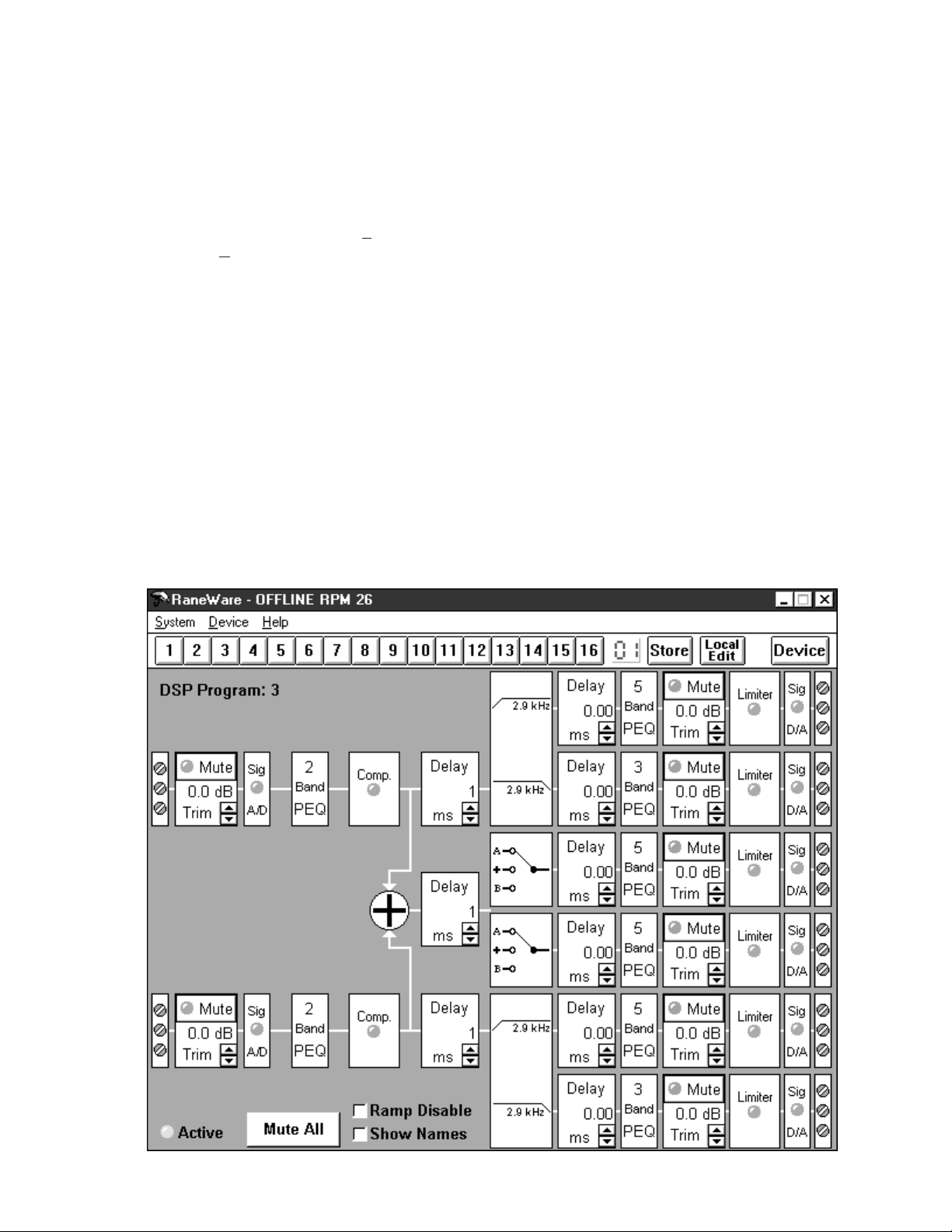
THE RANEWARE SCREEN
The RaneWare computer screen for the RPM 26 provides
an overall “system” picture of the available signal processing
functions. This screen (shown below) is called the Device
Edit screen. The RaneWare screen also contains a Button Bar
and typical Windows pull-down Menus. The RaneWare
screen gives you complete control of all signal processing
functions as well as access to all system-level controls such as
COM port selection and the Site Control Panel that recalls
memories stored in multiple RW 232 devices.
The “system” picture in each Device Edit screen contains
groups of independent signal processing “blocks” called DSP
Programs. The number of the loaded DSP Program appears in
the upper left corner, in this case, DSP Program: 3.
Each of these DSP Programs contains many processing
blocks. For example, each has at least one Input Trim block,
an A/D block with a dual-color Signal present and overload
indicator, Delay blocks, and so on. The RPM 26 contains
many variations of these user-selectable DSP Programs—
which are covered in more detail later in this manual.
RaneWare computer screens always display at a specific
size on the screen, optimized for typical laptop computer
screen resolutions. This makes it possible to view and control
multiple screens when your graphics resolution allows.
Manual-5
Page 6
RANEWARE MENUS
There are three RaneWare pull-down Menus.
The System menu for “system-level” controls that apply to
the computer or all connected RW 232 devices. The Device
menu for device-specific control and the Help menu for online help.
SYSTEM MENU
These menu commands apply to all connected RW 232
devices and contain the following menu items:
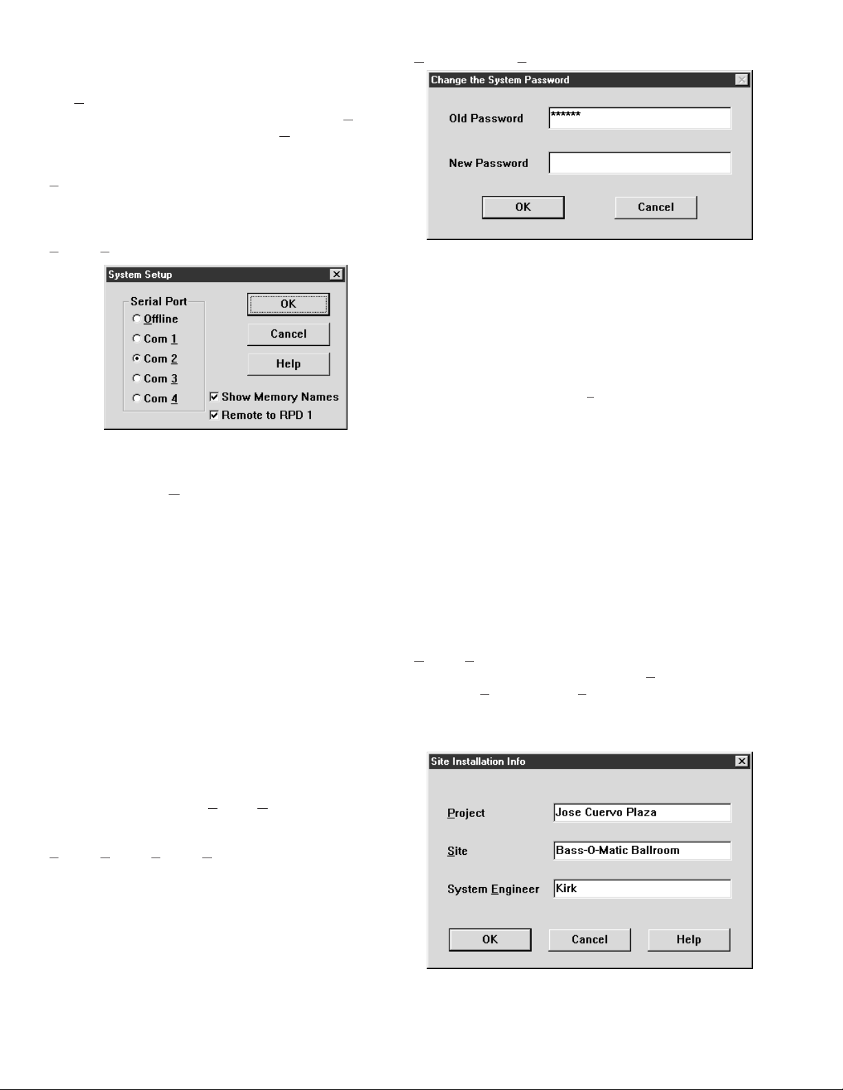
System|Change Password displays this screen:
System|System Setup displays this screen:
The Serial Port radio buttons on the left tell the computer
which Com port is being used to “speak” to the connected
RW 232 unit(s). The Offline radio button permits use of the
software without connecting a unit. To operate an RW 232
unit, you must select the Com (serial) port that is physically
connected to the unit. This screen is also displayed the first
time you start RaneWare or after erasing the RW232.INI file
from your Windows directory.
Most laptop computers have a built in mouse. If you use
an external mouse with your laptop, you may need to use the
built in mouse if your laptop does not have two serial ports—
one for the mouse and a second for the RW 232 unit.
Check the Show Memory Names check box to display the
Memory names in the RaneWare Button Bar whenever the
mouse is on top of a Memory recall button. Memory names
are edited in the Site Control Panel Setup window. (See Site
Control Panel Setup below.)
The Remote to RPD 1 check box is only used with
Rane’s RPD 1 product. Check this box only if you are using
an RPD 1 to remotely communicate with an RW 232 system.
When this box is checked, no communication with local RW
232 devices is possible. See Dial and Hang up below for more
RPD 1 details.
This window allows you to change the password. The
default password set by the factory at the time the software
ships is please. Passwords are case insensitive, therefore,
PlEASe, pLEasE, PLEASE and please are all equivalent. Type
the old password in the Old Password edit box, then type the
new one in the New Password box. Click OK. Then be sure to
note the new password somewhere, preventing future embarrassment.
Certain commands such as Lock Device (see page
Manual-9) or exiting from the Site Control Panel require the
correct password before they will execute.
Important Note: The computer stores the password, not
the units. Therefore, it is wise to think of the RW 232 password as the computer’s password, not as each individual
system’s password. This makes it easier to remember the
password since it will be the same for every installation where
you remove the computer once the system is set up. This also
provides the flexibility to have unique passwords for those
installations where a dedicated computer is left on site to
operate the system. If you return to an installation with locked
devices, and do not have the same computer used to initially
lock the devices, you will only need to know the computer’s
password, not the original password used to lock the devices.
System|Edit Installation Info
This selection allows you to enter the Project name,
installation Site and System Engineer for a given project. All
of these are printed on the Device Report printouts. Click in
the edit box or hold the Alt key and press the underlined
character to type new names.
System|Dial and System|Hang up
These selections are only used with Rane’s RPD 1
product. The RPD 1 is a telephone interface which, when
used with an external modem, allows remote diagnostics of
RW 232, AMX or Crestron systems. Thus, from the office, a
system designer can call a properly equipped remote system
to view and control that system’s RW 232 settings.
Manual-6
Similar to the password, the Site Installation Info is stored
in the computer, not in each unit. The Site Installation Info is
also stored with backup memories when you save a unit’s
memories to a file.
Page 7
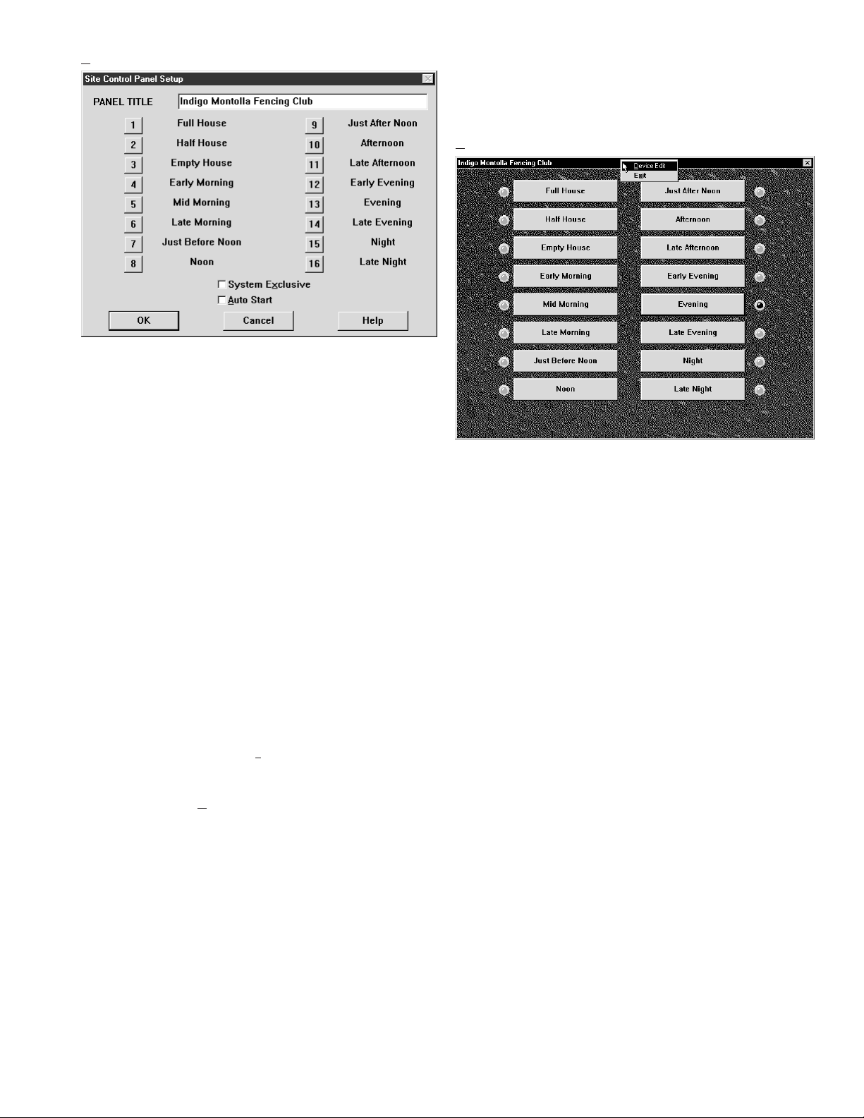
System|Site Control Panel Setup
RaneWare’s Site Control Panel (shown at right) is a sound
system re-configuration screen. It works by telling all
connected Rane RW 232 devices to switch immediately to a
designated memory that you have programmed in each unit.
Use the Site Control Panel Setup window (above) to
customize the Site Control Panel’s Title and Memory names.
There are 16 buttons available to use and each can be
renamed according to their assigned configuration. Initially,
the buttons are named Memory 1, Memory 2, etc., through
Memory 16. On the example screen above, you see that
Memory 1 is renamed Full House, Memory 2 to Half House,
Memory 3 to Empty House and so on.
A corresponding button will not appear on the Site
Control Panel if its name has been deleted. Thus panels can
be created with as few as 2 or as many as 16 buttons.
RaneWare also allows you to assign a unique title to the
Site Control Panel window. Thus, instead of the default title,
it could be Hotel Meeting Room Configurations or Sunday
Services. In this example, we’ve used Indigo Montolla
Fencing Club.
Note: You may also press the Tab key to move the focus
(i.e., the dotted line around the button) to the configuration
button you want, press the Enter key, then type the new name.
If you check the System Exclusive box, a user will not be
able to task-switch (Alt-Tab) away from the Site Control
Panel to other Windows applications.
If you check the Auto Start box, the Site Control Panel
will automatically appear each time you start the RaneWare
program. Otherwise, the panel appears in the last mode you
were in. If you were in the Device Edit screen when you
exited the program, Device Edit mode appears the next time
you run RaneWare. Likewise, if you exit from the Site
Control Panel, it appears next time you start the program.
Microsoft Windows can also be set up to start RaneWare
automatically by dragging the RaneWare program icon from
the RaneWare Group to the Windows Startup Group. Refer to
your Microsoft Windows manual for detailed instructions.
Important Note: The names you assign become the
memory names associated with each RW 232 device on line,
regardless of the type of device (RPM 26, RPE 228, ECS
Teleconferencing system, etc.). If you set up the button
corresponding to memory number 1 to represent a particular
sound system configuration, make sure memory number 1 in
each device in the system is pre-programmed appropriately
for this particular sound system configuration.
System|Site Control Panel
The Site Control Panel is RaneWare’s sound system reconfiguration screen. Depending upon how you set up the
control panel (using Site Control Panel Setup), up to 16
buttons can be displayed and each can have a unique name
representing a particular sound system configuration.
To operate the Site Control Panel, click on the desired
configuration button with the mouse. Notice that its adjacent
indicator illuminates red so you always know the current
sound system configuration.
For Windows 3.1 users:
To exit the Site Control Panel and the RaneWare program
click on the box in the upper left corner of the window. This
displays Windows’ system menu from which you can choose
Exit (Alt-F4). If you select Exit, you terminate the program
upon entering the correct password. Double-clicking the box
also exits RaneWare after entering the password.
To return to Device Edit mode, click on the box in the
upper left corner of the window. This displays Windows’
system menu; choose Device Edit. Upon entering the correct
password you return to the Device Edit screen .
Important Note For Windows 95 users:
While operating the Site Control Panel there is no buttonbox in the upper left corner for the system menu allowing you
to either exit or return to the Device Edit screen. There is,
however, a Close-Window button-box in the upper right
corner. As expected, the Close-Window button-box exits the
Site Control Panel, but unfortunately, it also quits the entire
RaneWare program. To get back to the Device Edit screen,
right-click the mouse on the Site Control Panel title bar. This
opens a menu (see picture above) allowing you to return to
Device Edit mode or exit RaneWare altogether. As usual, a
password is required for either option.
Manual-7
Page 8

DEVICE MENU
This menu applies only to the single, selected device you
are editing and contains the following:
Device|Select
The DEVICE SELECTION window displays the list of
available RW 232 units, including the OFFLINE versions of
each RW 232 product. The OFFLINE versions allow you to
operate the software just as if you had an actual unit hooked
up.
If the only devices shown in the Device Selection window
are the OFFLINE ones or if the list is inaccurate, click on the
POLL button with the mouse. During polling, the program
looks for connected devices by sequentially stepping through
addresses 1 through 250 (or until you click on the STOP
button in the Polling message box). When a device is found,
its name will be displayed in the DEVICE SELECTION
window.
Note: Since you know what addresses were assigned, you
may stop polling as soon as it has exceeded your last device’s
address. Depending on the number of devices connected,
polling may take approximately 30 seconds for as few as 6
devices to 3 minutes for 250 devices.
Note: You do not have to poll each time the program is
run, only when RW 232 devices are added, deleted, substituted, or have had their addresses changed.
Click the device you wish to edit from among those
shown in the window, then click OK (or just double-click on
the device). The Device Edit window for the device you’ve
selected appears allowing complete control of the device.
Device|Choose DSP Program
Choosing DSP Programs is covered in more detail in the
CHOOSING DSP PROGRAMS section on page Manual-11.
There are many intuitive DSP Programs available in the RPM
26. Each can be thought of as a unique audio system. Choose
DSP Program brings up a window allowing selection of these
various DSP Programs or systems. The following is just an
overview of the RPM’s DSP Programs.
Each of the RPM’s DSP Programs (or systems) is fixed. In
other words, the arrangement and type of the various signal
processing functions are not editable.
The RPM 26’s various DSP Programs provide:
• Display of all important control settings on one screen.
• Many useful signal processing blocks including: trim,
program compression, delay, input summing, I/O routing,
crossover, splitting, parametric EQ, limiting, pink noise
and sine wave generation.
• 16 memories to store the settings of all signal processing
blocks.
• Independent Input and Output muting, plus a Mute All button.
• Show Names check box for displaying the user assignable
Input and Output names.
Device|Load External DSP Program
This menu pick is for future RPM 26 capabilities. We
anticipate new DSP Programs that fulfill currently unrealized
applications. To support this, the Load External DSP Program
menu pick allows downloading a new DSP Program from a
computer to an RPM 26 without the need to replace firmware
chips. At the time of printing, no new DSP Programs are
available. We are working with James Doohan on a future
DSP Program that transports audio waves through space.
Device|Backup Memories to File
This menu item allows you to create or select a file in
which all the data in a device’s memories will be saved. To
save all the data stored in the device to a disk file, select the
Backup Memories to File command from the Device menu.
Type the name you want for the file in the File name: field or
select one of the files shown in the list box. Then press return
or click OK.
Note: You do not have to type an extension to the
filename (unless you want to). The program will automatically append .RPM as the file extension. Also, the current
project name, site, and system engineer information entered
through the Edit Installation Info dialog box is automatically
saved in each .RPM file.
Backing up device memories is highly recommended. Just
like any computer data, the RPM data should be saved to a
file, especially during and after detailing system settings.
Each RW 232 device saves its own settings internally; other
than the password, no settings are stored on the computer.
Having these settings backed up separately in a file provides
extra peace of mind as well as a convenient starting point for
similar or future systems. It is also wise to save a floppy disk
copy of each device’s settings—with the RaneWare Device
Printouts—in a hardcopy file. This provides complete system
documentation as well as a convenient backup of each device
should a replacement device ever be needed.
Device|Restore Memories from File
This menu item allows you to restore all memories and
names to a device from a selected file.
Note: All saved RPM 26 data files are given the default
extension .RPM.
Manual-8
Page 9

Device|Lock Device
Lock Device allows you to lock a device to prevent
unauthorized users from making changes to your programmed
settings in the device’s memories. Although a device is
locked, different presets can still be recalled by selecting
another memory via the Site Control Panel, the Remote
Switch Interface, or by clicking on a desired memory key on
the button bar with the mouse. The data previously stored in
the device’s memories, however, can
not be changed.
To Lock a
device, type in the
password in the
dialog box shown
above after selecting
Lock Device from
the Device menu.
When a device is locked, this icon appears to the right
of the Local Edit button on the button bar.
Device|Unlock Device
This menu selection restores a device to its unlocked state,
allowing changes to the data previously stored in its memories. You must type in the correct password before the device
will unlock and the lock icon disappears.
Device|Name Device
Name Device
allows you to name
each RPM 26 and
their channels. The
device and channel
names are stored in
the unit. Type the
unique name you
want for each RPM
26 in the Device
Name field, then
press the Tab key to
move the focus to
the next field. Type
the names you want
for each channel in the remaining fields, then click OK.
Device|Restore Names from File
This selection allows you to restore the Device, Input and
Output names from saved memory backup files without
changing any of the device’s current settings.
Device|Print Device Report
Selecting this item prints the current device settings from
the current or working memory. The control settings are
printed in a tabular format so you know precisely where each
control is set. Also printed is the Project, Site, and System
Engineer information you entered in the Edit Installation Info
dialog box, plus four blank lines for handwritten comments
and the report date.
Each of the RPM’s parameters are printed including the
DSP Program with its description, the device address, device
name, the memory number and memory name. The device
report for each RPM 26 memory is 7 pages, one for the Input
parameters and one page for each Output which includes each
output’s overall response curve.
Device|Print Device Report from File
This menu item prints device settings from a stored file
instead of a connected unit. This allows you to setup a
system, save the system’s settings to a file and print them at
your office; saving you the hassle of dragging your printer to
each site just to print out device settings (though this may
impress your client).
Once you select
the file with backedup memories to
print, the following
window appears:
You can select
one or more
memories to print.
To select a single memory to print, click on your choice then
click OK. As with many Windows selection boxes, to select a
contiguous range of memories, click on the first memory
choice, then hold down the Shift key and click on the last
memory choice of the range. This is a handy way to print
memories 1 through 5 for example, or even all 16 memories.
To select a random group of memories to print, click on the
first choice, hold down the Ctrl key and click on any subsequent memory choices. Repeat this process until all the
memories you want to print are selected, then click OK.
Device|Device Status
Device Identifier is a unique number assigned to each unit
by the factory. It’s more for our information than yours.
Hardware Rev is the current revision number of the unit’s
hardware.
Firmware Rev is the current revision number of the unit’s
firmware. This is the software that is installed in each unit and
controls the actions of the internal microprocessor.
Total Running
Time is the total
amount of time that
the unit has been
operating (powered).
Data Timeouts
is the number of
times RaneWare
failed to communi-
Manual-9
Page 10

cate with the selected unit since software launch. This number
should always be zero but could increase if the communications cabling becomes intermittent or open.
Note: Be sure you have the above Device Status informa-
tion as well as the version number of RaneWare you are using
(found under Help|About...) when calling the factory for
technical support.
HELP MENU
The Help menu provides extensive On-Line Help. There
is a help Index and a help Contents (F1) interface for quick
access to the information you may seek.
Also, the infamous About... selection displays the beautiful RaneWare splash screen where the current RaneWare
application software revision is available. The revision
number in Help|About... is very important if you ever need
RPM 26 or RaneWare technical support from Rane.
THE RANEWARE BUTTON BAR
This Button Bar appears at the top of every RW 232
product’s screen.
The 16 numbered buttons immediately recall the indicated
memory number from the connected RW 232 product. The
most recently recalled memory is indicated by the red
memory number to the left of the Store button. The red
memory number flashes when the current memory settings
have changed and no longer match the settings stored in the
flashing memory. If you wish to save the changed settings in
one of the 16 memories, click Store, and then click the
memory number in which you wish to store the settings. It’s
that easy! Go ahead and store different settings in different
memories. After storing a few, click any memory number to
instantly recall that memory. Store those settings you’ll use
most often in memories 1 through 8, since these can be
recalled via the rear panel Remote Switch contact closures
when the computer is removed.
Note: When you click the Store button, it appears in lightgray until you select a memory in which to store the current
data. The red, most recently recalled memory number does
not change to the memory number you’ve stored to. As an
example, if you recall memory 3, make some changes, then
hit Store followed by memory 5 to store the changes in
Memory 5, the red memory number continues to indicate
memory 3 as the most recently recalled memory. Only if you
hit the memory 5 button a second time (after Storing) will
memory 5 actually be recalled. This means that storing to a
given memory does not automatically recall that memory.
To change any settings without affecting the audio, simply
select the Local Edit button, make the changes, then re-click
Local Edit. You will be asked: Accept the Changes?
Answering Yes sends those settings to the RPM. While Local
Edit is selected, clicking on any of the memory buttons
displays that memory’s settings without recalling them.
The Device button brings up a selection menu of up to 15
RW 232 units connected to the computer from the most recent
Poll. Simply select the device you wish to control.
RPM 26 BASICS
The RPM 26 has 2 inputs, named Input A and Input B;
and 6 outputs, named Output 1 through Output 6. To display
these default names on the Device Edit screen, check the
Show Names box at the bottom of the screen. These are the
default names of the RPM’s inputs and outputs. To change
these I/O default names or the device’s name to those that
apply to your install, select Name Device under the Device
menu.
RAMPING
When the Ramp Disable check box at the bottom of the
Device Edit screen is unchecked, the RPM 26 slowly ramps
level and EQ setting changes. Ramping is provided as an
application level feature. For example, when changing from
one memory to another with program audio playing and
where EQ or level settings change, it is appropriate to ramp
between memories. During set up, however, it may be
distracting or deceiving to have settings ramp. Check the
Ramp Disable box during set-up to avoid, for example,
running analysis sweeps too quickly after a change – i.e.,
before the RPM settings finish ramping. Checking this box
during set-up steers you clear of scratching your head on the
first sweep and finding that the second sweep is just fine.
Ramp Disable and Show Names states are not stored in
memories — the unit either has ramping enabled or disabled.
Ramping affects the following processing functions: All
Trim controls (including Invert and unmuting), all PEQ
Filters (including Frequency, Level, Q and Filter Type
changes), Crossover and High & Low Cut Filters (Type &
Frequency changes) and the Compressor Ratio & Threshold
settings. Every time you change DSP Programs these settings
always ramp. Filter bypassing is never ramped. Mute controls
always attenuate quickly and ramp back up when ramping is
enabled. Enabled ramping is recommended once set up is
complete, to avoid small ticks and tiny pops that may occur
when ramping is disabled.
When enabled, ramping occurs while you are editing
settings “live” with a unit or while you are recalling different
memories. The ramp rates may be deceptive until you get
used to them. For example, when you unmute an output with
ramping enabled, the level slowly ramps up to its displayed
setting. Ramping is also implemented for Level (boost/cut)
settings and Frequency settings in all PEQs. When changing
from one memory to another where the PEQ settings change
or when editing filter values “live,” the RPM ramps between
like-numbered PEQ filters. For example, Filter 1’s Level and
Frequency settings slowly change from their initial value to
Filter 1’s new values. Filter 2’s settings do the same, et
cetera. Ramping is disabled via the Ramp Disable checkbox
at the bottom of the Device Edit screen.
It is wise to keep like-numbered filters in a similar
frequency range when changing memories. For example,
always set filter number one as your lowest frequency PEQ
filter. This way, when changing memories where filters move,
Manual-10
Page 11

the ramping algorithm is most efficient and therefore least
noticeable. If the Frequency settings change dramatically and
the Level changes, then the Level of the Filter is slowly
brought to zero, the Frequency value is changed, then finally
the Level is ramped to the new value.
PEQ Levels ramp in ½ dB steps and Frequency settings
ramp in 1/24 octave steps (all other filters ramp in 1/6 octave
steps). The ramping algorithm is based on the number of
these steps and works as follows: When changed, the new
settings for PEQ Level & Frequency are compared to the old
settings. If, in steps, the Frequencies are closer than the
Levels, the settings simply ramp to the new values. If the
Frequencies are “farther apart” than the Levels (i.e., for large
frequency changes), the Level ramps to 0 dB as the Frequency ramps slowly toward the new settings. When the
Level reaches 0 dB, the frequency is abruptly changed to the
new setting, then the Level ramps to its new setting.
CHOOSING DSP PROGRAMS
The RPM 26 contains predefined DSP Programs. The DSP
Programs are “fixed” and the placement and order of the
signal processing functions cannot be edited.
Each DSP Program can be thought of as a unique “system
setup.” For example, there are 2-way crossover programs, 3way programs, 2 x 6 splitter programs, etc. The RPM 26’s
default DSP Program is Program number 3. Program 3
provides a Dual 2-way crossover system, complete with
program compression, delay, parametric EQ, limiting and two
extra outputs with delay that are useful for mono or stereo
subs or two full range outputs.
To select a different DSP Program, select Choose DSP
Program from the Device menu. A dialog box listing of the
available DSP Programs appears, as shown below.
The number on the left
side of the descriptions
indicates the DSP Program’s
number. A simplified graphic
of the DSP Program indicates
the general audio system flow
for each Program. Only the
number of available parametric EQ filters and crossover
type (if applicable) are shown
in this simple graphic. All
DSP Programs, however, do
provide additional processing
blocks not shown. The
additional processing blocks
vary from Program to
Program but always include
Input Trim, Output Trim,
Meters and Delay. Program
Compression and Limiting are
available in most DSP
Programs. Input Summing,
test signal Generators and I/O
Routing — available in some
DSP Programs — are also shown in the simplified graphic
where applicable.
To help find a desired DSP Program, the Inputs and
Crossovers check boxes near the top of the screen allow the
user to reduce the DSP Program list to include only those
Programs matching the checked criteria. For example, if one
desires only two input, 3-way crossovers, de-select all but the
Two Input and 3-Way check boxes. The displayed list is then
reduced to only two DSP Programs — both Programs 4 and 5
provide a Dual 3-way Crossover. To quickly show all
available DSP Programs, click the Reset button.
A few lines describing each DSP Program are listed.
Generally these descriptions duplicate information available
in the simple graphic, but some DSP Programs provide much
greater functionality than the simple graphics indicate. For
example, some DSP Programs contain “Extended” parametric
EQ, shown with a plus sign after PEQ (PEQ+). DSP Programs
with PEQ+ permit multi-way crossover implementations since
two filters in each Extended Parametric can be changed to
crossover filters such as Linkwitz-Riley, 24 dB/Oct., etc.
Each time you change DSP Programs from this window,
all settings revert to their defaults and all outputs of the newly
loaded DSP Program are automatically muted. This is not the
case, however, when recalling a new DSP Program during a
Memory change.
Important Note: Each of the 16 Memories can contain a
different DSP Program. Before connecting the RPM 26 to
other audio system components, it is wise to choose the
appropriate DSP Program and store this program in each of
the 16 Memories. This avoids the problem of accidentally
recalling a Memory that restores an undesired DSP Program;
such as the case where you recall from a 3-way DSP Program
to a splitter: this sends full-range audio to all Outputs!
Manual-11
Page 12

PROGRAMMING THE RPM 26
Each DSP Program contains a number of processing Blocks. There is a Block shown for each available signal process-
ing function. The quantity and type of available processing blocks varies from DSP Program to DSP Program.
Double clicking on most of these processing Blocks opens a detail window where most processing settings are edited.
Assuming your computer screen provides enough graphics resolution, up to three of these detail windows can be open at
any one time. In addition, a fourth window that displays the Overall Response curve for a given output can be opened by
double-clicking any output’s screw terminal graphic. Once a detail window is opened, settings can be edited. The window
can then be closed and the changed settings are retained in the working memory (memory zero). Changes are not stored in
any other memory until you save them with the Store button.
It is not possible to Alt-Tab to another Windows application while any RPM Detail Window has the focus. You can,
however, Alt-Tab from the RPM’s main Device Edit screen when it has the focus. This allows you to toggle between
Windows applications and still keep the RPM’s Detail Windows open on the screen.
INPUT TRIM
The Input Trim processing block is on the
left side of the Device Edit screen, just to the
right of the input screw terminal. This block is
shown here:
The Input Trim operates the RPM’s
internal analog level control whose sole
purpose is to provide the analog-to-digital converter with the
proper voltage level. Click on the up and down arrows to
increment or decrement the Input Trim.
For more precise control of the Input Trim, double click
on the Input Trim block. You may double click anywhere
except on the arrows or on the Mute button to open the detail
window, shown below.
The name of the processing block appears at the top of
each detail window, in this case, input Trim A. The horizontal
scroll bar adjusts the Trim control in three ways. Clicking the
left or right arrows adjusts the trim in ½ dB steps. Clicking
between the arrows and the sliding box (Thumb) adjusts the
Trim in 5 dB steps. Clicking and holding the Thumb allows
you to drag the control.
Two meters are shown in the Input Trim detail window.
The Input meter on the left shows the voltage level (in dBu) at
the screw terminal input of the RPM 26. Adjusting the Trim
control has no effect on this Input meter. Clicking the input
Mute button turns this meter off, even though Input signal
may still be present. (The front panel’s
Input signal present LEDs always show the
presence of incoming audio, ‘pre-trim.’)
The A/D meter on the right shows the A/D
level (in dB Full Scale), and indirectly
shows the number of bits being toggled by
the input signal after passing through the
input level control. Clicking the Mute
button also turns this A/D meter off.
To set the Input Trim, please read the
rest of this section and the A/D, D/A &
METERING section below. With the
amplifiers turned down or off and all of the
RPM’s outputs muted, apply your system’s
expected average audio level to the RPM
26. The Input meter displays this voltage as
long as the Input Mute is not active and the
level is not set too high (clipping). The
RPM 26 is designed to receive +20 dBu of
input and send the same +20 dBu out. This +20 dBu is
designed to be zero dB Full Scale (dBFS) at the A/D converter (i.e., maximum input to the A/D converter) when the
Input Trim is set to 0.0dB. Set the Input Trim so your
nominal signal level lights the A/D meter indicator corresponding to your system’s required headroom.
For example, let’s assume your system requires 16 dB of
headroom. Set the Input Trim until the -16 dB A/D meter
indicator lights with an average signal level present. This
corresponds to a nominal input signal level of +4 dBu. If you
run a system with less headroom, let’s say 12 dB, set the
Input Trim until the -12 dB A/D meter indicator lights. This
corresponds to a nominal input signal level of +8 dBu. If you
tend to use a lot of EQ boost at mid or especially low frequencies, turn the Input Trim control down to compensate for the
low frequency boost. Refer to the enclosed RaneNote “Setting
Sound System Level Controls” for more information.
The Input Trim control should never be set such that your
highest signal peaks toggle the A/D meter’s +0 dBFS
indicator. This is where the A/D converter clips. The RPM
clips cleanly. It is important to toggle as many bits as possible
on the A/D converter. Toggling as many bits as possible is
precisely equivalent to maximizing signal-to-noise ratio in
analog audio systems. The Input Trim should never be used as
a “system” level control. This is why there is only 12 dB of
attenuation available on the Input Trim.
If the functionality of the Input Mute
button is unclear, perhaps trying to explain
it would be moot. Remember that the signal
ramps back to its setting after unmuting
unless ramping is disabled.
When checked, the Input Trim Linked
check box “ties” the two Trim controls
together. (The Mute buttons can not be
linked.) Both Input Linked boxes must be
checked in order for the controls to
function together. This functionality
provides a Linked or “stereo” Input Trim
and also permits offsetting the two controls, then linking them. A red ‘1’ appears
in the Input Trim block on the Device Edit
screen when the linked box is checked.
This indicates the control is linked without
needing to open the detail window.
Manual-12
Page 13

OUTPUT TRIM
The Output Trim looks, feels and acts in
much the same way as the Input Trim. So,
read the INPUT TRIM section on the previous
page for basic operating instructions. The two
Trims differ by the location on the screen, the
single Output Meter, the Link functionality
and, most importantly, their purpose. The Output Trim’s
purpose is to provide up to 30 dB of attenuation on each
output. This is useful to adjust for speaker sensitivity in both
distribution and crossover applications where each output
may require a slightly different level. Use the Mute button to
turn individual outputs off.
Since this is a digital attentuator and only the audio is
attentuated — noise is not attenuated, use the output Trim
sparingly since each dB of attenuation decreases the signalto-noise ratio. In extreme attenuation cases, it is better to
adjust the amplifier sensitivity controls for the best signal-tonoise. The Output Trim’s detail window is shown here:
The Output Meter displays the voltage level at the output
screw terminal of the RPM 26 in dBu. The Mute button mutes
the given output. The Invert check box inverts the polarity of
the given output. When ramping is enabled, each time the
Invert box is changed the given output’s level ramps to off ,
the polarity is inverted and the level ramps back up. Many
people frown upon purposely inverting the polarity of an
audio signal. The invert function here is provided solely as a
convenient tool for testing polarity. In permanent installations
it is always wise to correct polarity inversion problems
through other more permanent or “hardware” means such as
correcting cable-wiring errors.
The Link selection box “ties” groups of output Trim
controls together. There are 4 possible groups, None, 1, 2 or
3. None in the selection box indicates the given output is tied
with no other output. If two outputs’ Link boxes share a
common value, for example 1, then those two output trims are
linked together.
A/D, D/A AND METERING
Now, a word about metering and our
pal, the Windows operating system.
Displaying meters on computers poses a
unique problem for software designers and
sometimes for users, especially if you have
a “slow” computer. Everyone is familiar
with analog meters without computers deciding that displaying meter indicators needs to wait until a “more important”
task is completed. Windows provides the RPM 26 software an
update window opportunity every 100 milliseconds (10 times
per second). And, since there are more than just meters to
update, other functions at the computer’s discretion can have
a higher priority than the meters. This simply translates into
“the more meters you have on the screen, the more sluggish
and inaccurate they will appear.” For this reason, it is wise to
adjust the RPM’s Trim controls or view its meters one at a
time. This displays the least number of meter indicators on
the screen, making the display’s update rate as reliable as
possible.
The A/D and D/A blocks on the RPM 26 Device Edit
screen indicate where in the signal chain the A/D and D/A
conversions occur. These blocks also contain the signal
present and overload indicators, all of which default to single,
two-color indicators: green for signal present, red for overload and gray for no signal detected.
Double clicking on any of the A/D or D/A blocks turns the
block into an eleven segment meter. On the A/D block, these
meter segments correspond to every third segment from the
A/D (dBFS) meter. The segments on the D/A block also
correspond to every third segment from the Output meter.
The top segment lights at -2 dBFS, each subsequent segment
lights 3 dB before the segment above it. Again, to keep the
meters as reliable as possible, keep as few meter segments on
the screen as possible when adjusting levels.
The RPM 26’s front panel Input signal present LEDs are
familiar analog implementations. The remaining meters —
the input overload and all output meters — are microprocessor controlled but have a guaranteed update rate of 90
milliseconds, or just over 11 times per second.
Manual-13
Page 14

HIGH & LOW CUT FILTERS
High and Low Cut filters are provided in
some DSP Programs. Their purpose is to bandlimit the system’s frequency range. Not all
installations require 20 to 20 kHz bandwidths
for their audio systems. Use the High and Low
Cut filters to remove the generally undesirable
frequencies below 80 or 100 Hertz and above 15 to 18
kilohertz. These frequency ranges are simply examples, since
often each system requires a unique range.
The detail window for the High and Low Cut filters is
shown here:
Like all detail windows, the name of the window is
displayed at the top. The edit boxes at the bottom of the
window show the current Low Cut and High Cut frequency
settings in Hertz. To edit the current values, click the up or
down arrows, or click in the edit box to display the cursor and
type a new value. The High and Low Cut filters are fixed
Butterworth, 24 dB/Oct. (4th order) filters.
The Bypass check boxes on the High and Low Cut detail
window turn the filters completely off. Note that this is not
equivalent to simply setting them to their highest (20 kHz)
and lowest (20 Hz) frequency settings. Toggling these
Bypass check boxes provides an easy way to compare
filtered versus unfiltered responses, just be sure you don’t
cause any damage by bypassing the high or low cut filters.
The filters ramp between settings whenever Bypass is
toggled and ramping is enabled.
Adjusting the filter frequency settings is also possible if
you click and drag directly on the graphed curve itself. You
must click directly on the curve’s downward slope, on the
high or low frequency side, to successfully grab the curve and
alter the settings. The curve changes color when successfully
“grabbed” and the 3 dB down point of the curve snaps to your
cursor’s position. This 3 dB down point defines the frequency
setting for each filter.
PARAMETRIC EQ (PEQ)
Every DSP Program contains multi-band
parametric EQ, abbreviated PEQ. The quantity of
PEQ filters varies from program to program. The
PEQ block shown at the right contains 5 filters.
Some DSP Programs have parametric EQ in both
the Input and Output (see INPUT BLOCKS &
OUTPUT BLOCKS on page Manual-20). Parametric EQ can
be used for a wide variety of purposes. Generally, input
parametric is used for program sweetening and/or bandlimiting the frequency range. Output parametric can be used
to correct for loudspeaker response anomalies, or if used
sparingly, to sometimes overcome acoustically created room
anomalies. In distribution applications, output PEQ provides
independent equalization of each zone.
The quantity of PEQ filters may vary with each program,
but the operation of the PEQ filters is consistent. Double
clicking on any PEQ block opens that PEQ’s detail window
where all parametric parameters are adjusted. The detail
window is shown at the bottom of this page.
The name of the open PEQ block appears at the top of the
window. The graph contains some quantity of circled numbers, each representing an available parametric EQ filter. The
location of each circle on the graph determines that filter’s
frequency in the x-direction (left-right) and level (boost/cut)
in the y-direction (up-down). Across the bottom of the screen
are edit boxes displaying the selected filter’s current settings.
The left-most Filter edit box displays the currently selected
filter number. This same filter appears on the graph in a
different color with its corresponding number circled. The
plotted contribution of the selected filter also appears in a
different color. This makes it easier to see the contribution of
each individual parametric filter. It is also convenient to
simultaneously open the Overall Response curve for the PEQ
output you are viewing (double click on the Output’s screw
terminal). This provides the calculated overall response of all
viewed PEQ filters. (See OVERALL RESPONSE on page
Manual-19 for further details.) Click on the Filter edit box’s
down arrow to display and select a different filter’s settings.
You may also click directly on the circled number on the
graph corresponding to the filter you wish to edit or view.
The Freq (Hz) edit box is changed with the up or down
arrows. Or click in the edit box to display the cursor and type
a new frequency value, always in integer Hertz.
The Level (dB) edit box is also changed with its up or
down arrows. Or click in the edit
box to display the cursor and
type a new level value in dB.
The Level’s step size is ¼ dB
(0.25). The boost range is +12
dB, the cut range is -15 dB.
Typed values are truncated to
the nearest value, not rounded
high or low.
The Filter Type selection box
is edited by clicking the down
arrow and selecting a new Filter
Type such as Low Shelf, High
Cut or a Normal parametric
Manual-14
Page 15

filter. (See the EXTENDED
PARAMETRIC section below
for additional filter types such as
Linkwitz-Riley, Bessel and
Butterworth filters.) Those
systems that require constant
directivity horn equalization can
use the High Shelf PEQ Filter
Type in combination with other
PEQ filters to achieve the
appropriate EQ for the combination of horn and compresssion
driver you are using. For
optimum frequency response, use
an analyzer to achieve the best
possible horn EQ compensation.
The bandwidth, abbreviated BW(Q), for each parametric
EQ filter is edited with the horizontal scroll bar. There are 80
steps between a Q of 40 and 0.5. This is a bandwidth of
between 0.036 and 2.543 octaves respectively. The horizontal
scroll bar adjusts the bandwidth control in three ways.
Clicking the left or right arrows adjusts the bandwidth one
step at a time (one step is a BW(Q) change of 0.025 octaves).
Clicking between the arrows and the sliding box (Thumb)
adjusts the bandwidth steps 0.25 octaves at a time. Clicking
and holding the Thumb allows you to drag the control.
A Bypass check box appears on the bottom right allowing
the selected PEQ filter to be bypassed. This is essentially
equivalent to setting that filter’s level to zero. This is useful
when comparing the effect of a single PEQ filter’s frequency
response contribution. A small red ‘X’ appears over the top of
the circled filter number to indicate that the filter is bypassed.
(See filter #4 on the example screen to the left.) The bypassed
filter’s response graph does not change on the parametric
graph, but it does on the Overall Response graph (double-
click on the Output’s screw terminal). The Overall Response
curve also shows the contributions of the crossover and the
high/low cut filters (if applicable). See the OVERALL
RESPONSE section on page Manual-19 for further details.
A right mouse click on the parametric detail window pops
up a menu allowing flattening of the current (Flatten Filter
Level) or all PEQ filters (Flatten All Filter Levels). This same
right mouse click menu allows bypassing all PEQ filters (All
Filters Bypassed) for conveniently comparing equalized and
unequalized settings.
You can also Copy (select Copy) and Paste (after
Copying) the PEQ settings from one PEQ to another from
this menu. The PEQ copy and paste scheme allows you to
copy, for example, the first three PEQ bands from a 6 band
parametric into a 3 band PEQ. The three extra bands, 4, 5 & 6
in this case, are simply ignored by the 3 band PEQ. The same
goes for pasting from a 3 band into a 6 band PEQ. Only the
first three bands’ settings will be copied into the 6 band PEQ
and bands 4, 5 and 6 will be unchanged after the paste.
This makes it easy to set up one processing block, then
copy settings to other blocks.
EXTENDED PARAMETRIC (PEQ+)
Some DSP Programs provide “Extended”
Parametric EQ, abbreviated PEQ+. Extended
parametric simply means that two of the available
PEQ filters contain extended capabilities. These
two special PEQ filters support various EQ filter
types, such as high pass (HP) or low pass (LP)
Linkwitz-Riley, Butterworth or Bessel filters, these are
abbreviated LR, BW and Bsl, respectively. Different slopes
for each of these filter types are also available, allowing 12
dB/Oct., 18 dB/Oct. and 24 dB/Oct. filter implementations
(2nd, 3rd or 4th order), where applicable. In any extended
parametric, only the first and last filters contain the extended
capabilities; 1 and 8, in the above example screen.
The purpose of Extended Parametric is to give the RPM
26 the capability to implement up to a 6-way crossover. Since
each PEQ+ output can implement any crossover frequency
range, treating each output as its own crossover band,
provides multi-way crossovers.
Hint: For midband crossovers, use 2 bands with one set
for LP, the other set for HP and overlap them.
Note: Operation of Extended Parametrics (PEQ+) is
exactly like regular parametrics (PEQ), the only difference is
when you choose Cut, LR, BW or Bsl filter types for a given
filter, the Level and BW(Q) settings for that filter have no
effect and are ignored by RaneWare. The Shelving filter type
also ignores the BW(Q) setting.
COMPRESSOR
Most DSP Programs provide a program
compressor on each input. The compressor’s
purpose is to alter the dynamic range of the
incoming signal. Compressors are simply fancy
volume controls. Only the volume level is
altered by compression. When compression
occurs, the compressor turns the volume down in a tightly
controlled manner. The Threshold is a voltage level setting
above which compression (or turning down the volume)
occurs. The Ratio tells the compressor how much to turn the
volume down for a given increase above the Threshold. The
Attack time dictates how quickly the signal reaches a
“settled” compression level for a given input signal step size.
The Release time dictates how long it takes the output signal
to reach a “settled” level after the input signal is reduced.
Manual-15
Page 16

The Comp. indicator lights yellow when the compressor
threshold has been reached. All other Compressor settings are
adjusted in the Compressor detail window shown at the
bottom of this page.
Double-clicking on the Compressor block opens the detail
window. The name of the open Compressor appears at the top
of the window. The detail window contains a scroll bar for
adjusting the Threshold, Ratio, Attack time and Release
time. A gain reduction meter is also provided that indicates
the amount of gain reduction (attenuation) in dB. The
Compressing indicator at the bottom left corresponds to the
top Gain reduction indicator and to the yellow indicator
shown on the Compressor block on the Device Edit screen.
The Compressor uses an RMS detector for Threshold
detection. Avoid short Attack and Release times as they can
audibly distort the signal, especially when the signal contains
mostly low frequencies.
The Combine check box allows logical “or-ing” of the
compression settings. Only if both channels’ Combine boxes
are checked will the “or-ed” settings apply to both channels.
When both boxes are checked, and after either channel
reaches its Threshold setting, both compressors will “follow”
each other with the same gain reduction, Attack and Release
times being applied to both channels. The channel with the
most gain reduction always dictates what instantaneous gain
reduction, attack and release settings are applied to the
combined channels. This maintains the spectral balance
between the two channels and keeps your stereo program’s
left-to-right sound stage intact.
If only one channel’s Combine box is checked, that
compressor uses the higher gain reduction value of the two
compressors as well as that same compressor’s Attack and
Release times. The unchecked channel acts by itself.
The Compressor’s Threshold and Ratio settings can also
be edited if you click and drag directly on the graphed curve
itself. You must click directly on the curve, to the left of the
Threshold point (or knee), to alter the Threshold. The vertical
position of the cursor corresponds to the Threshold level once
the curve is successfully grabbed. Click directly on the curve
to the right of the knee to alter the Ratio setting. The curve
changes color when successfully grabbed.
DELAY
All DSP Programs provide two types of Delay blocks.
Coarse Delay in the Input Block section, before the crossovers or splitters, and Fine Delay in the Output Block, after
the crossovers or splitters.
COARSE DELAY
The Coarse Delay block provides 1
millisecond minimum step sizes. Coarse Delay
is useful in speaker stack applications where
stacks are placed many feet in front of the
stage or for distributed
speakers that are far
from the sound source.
One millisecond is
approximately 1.13 feet
or 0.34 meters.
The up or down
arrows in the Coarse
Delay block (shown at
above right) increment
or decrement the Coarse
Delay without opening
the detail window.
For direct or scroll
bar editing, open the
detail window by
double-clicking on the Coarse Delay block. This opens the
Coarse Delay detail window where a scroll bar provides three
easy ways to edit the delay value. Click the left or right
arrows to adjust the delay one millisecond at a time. Click
between the arrows and the sliding box (Thumb) to adjust the
delay in 10 millisecond steps. Click and hold directly on the
Thumb to drag the control. Click directly in the edit box to
display the cursor and type in the desired value.
Note: The Coarse Delay’s minimum setting is one millisecond. Values less than 1 millisecond are not valid, since the
minimum time it takes signal to propagate through the RPM is
one millisecond. This minimum Coarse Delay displays the
propagation delay of the RPM 26. In other words, what you
see is what you get.
The Global Settings for Delay
Units (milliseconds, feet and meters)
and Temperature are covered next,
under FINE DELAY.
The Coarse Delays can be locked
together by checking the Linked box.
A red ‘1’ appears in the Coarse Delay
block on the Device Edit screen when
the Linked box is checked. This
indicates that the control is linked
without the need to open the detail
window. The delays are not linked
together unless at least one pair of
Linked boxes are checked.
Manual-16
Page 17

FINE DELAY
The Fine Delay block has 20 microsecond
(0.02 msec) minimum delay steps and is
intended to allow individual driver alignment
in speaker stacks or for lobe steering. Twenty
microseconds is approximately 0.02 feet (about
¼") or 0.00635 meters
(which gets rounded to
0.01 meters in the RPM
26).
The Fine Delay
block and Fine Delay
detail window are shown
to the right. Like the
Coarse Delay block, the
Fine Delay block
provides up and down
arrows for incrementing
and decrementing,
however the Fine Delay
has 20 microsecond steps that are always displayed as 0.02
milliseconds. The Fine Delay detail window provides three
ways to edit the delay value; single steps by clicking the left
and right arrows, 0.20 millisecond steps by clicking between
the Thumb and the arrows or clicking and dragging the
Thumb itself. Click directly in the edit box to display the
cursor and type in a new value.
The Global Settings for Delay Units (milliseconds, feet
and meters) and Temperature are displayed in both the
Coarse and Fine detail windows. These are global settings,
meaning that once changed, the changes appear throughout
the RPM 26. To change all displayed delay settings to
different units, click the down arrow in any Delay Units
selection box and select the new units from the list. Edit the
Temperature by clicking the up or down arrows or click
directly in the edit box to display the cursor and type in a new
Temperature. Click one of the radio buttons to display the
Temperature in either ‘F’ for Fahrenheit or ‘C’ for Celsius.
Only when distance units (feet or meters) are used does
the Temperature setting impact the displayed units. The
Temperature is calculated with dry air for the displayed
distances. The RPM 26 does not alter the delay time when the
Delay Units are changed, only the way the delay is displayed
is altered. Also, even though the displayed values may be in
feet or meters, clicking the scroll bars and arrows still changes
the delay times in milliseconds (1 msec. for Coarse Delay and
0.02 msec. for Fine Delay).
The Link selection box in the Fine Delay detail window,
“ties” groups of Fine Delays together. Select the down arrow
to the right of the selection box to assign Link groups. There
are 4 possibilities, None, 1, 2 or 3. None in the selection box
indicates the given delay is tied with no other delay. If two
delays’ Link boxes share a common value, for example, 2,
then those two delays are Linked together. When Linked, the
selection box’s number—1, 2 or 3—also appears in red in the
Fine Delay block on the Device Edit Screen. This indicates
which Link group a given delay block is in without needing to
open the detail window.
CROSSOVERS
Both 2- and 3-way crossover blocks are
found in various DSP Programs in the RPM.
Up to a mono 6-way crossover can be
implemented with the RPM’s powerful
Extended Parametric EQ, see the EXTENDED PARAMETRIC (PEQ+) section on
page Manual-15 for details on implementing
more than a 3-way crossover. The 2- and 3way crossover interfaces are similar. Only the
3-way is covered here. The 2-way interface
simply removes one band. The 3-way
crossover block is shown here:
The current crossover frequency settings
are shown on this block, making it unnecessary to open the detail window to check the
crossover’s current frequency settings. The
high frequency output of the crossover block
is graphically always on top with the lowest frequency
outputs displayed on the bottom.
Double-clicking on the Crossover block brings up the
Crossover detail window shown at the bottom of the following page. The graph displays the calculated frequency
response of the RPM’s outputs. For viewing ease, each
frequency band is displayed in a different color. Below the
graph are edit boxes, one for each crossover frequency point.
Edit each frequency by clicking the up or down arrows or
click directly in the edit box to display the cursor and type in
the new crossover frequency directly. The RPM 26 accepts
crossover frequency in 1 Hertz steps and all values must be
typed in Hertz.
Editing of the crossover frequency values is also possible
by clicking directly on the graphed curve. Click directly on
the intersection of the two curves to successfully grab and edit
the crossover frequency. The curves change color when
successfully grabbed. The horizontal position of the cursor
dictates what frequency value is assigned once you drop the
cursor.
Note: It is wise to alter crossover frequencies directly on
the graph only when the outputs are muted or when the RPM
26 is not connected to amplifiers and speakers. This avoids
the potential disasters of slipping with the mouse or reaching
for your latté and accidentally clicking the mouse! For these
reasons, the area to successfully grab the crossover curve is
small.
For both the 2-way and 3-way crossover blocks, the
default crossover filter type is Linkwitz-Riley, 24 dB/Oct. (4
order) filters. The crossover frequency points are also locked
together making all adjustments equivalent to familiar analog
crossovers. For those with the proper analysis tools to
properly adjust other crossover filter types, the RPM’s
crossovers contain an Advanced mode. In the crossover detail
window, clicking the right mouse button pops up a menu that
provides access to the Advanced mode. A Warning box is
displayed before one can enter Advanced mode. Check the
Don’t ask me again box if you “know what you’re doing”
and this whole warning business is beneath you. Click OK
only if you have the proper equipment to ensure your crossover adjustments are helping, not hindering your efforts. Hit
th
Manual-17
Page 18

Cancel if you lack the proper analysis tools.
Once in Advanced mode, more edit boxes appear allowing
precise control of each individual filter type, slope and
frequency. This allows Linkwitz-Riley (LR), Butterworth
(BW) or Bessel filters with 12, 18 or 24 dB/Oct. slopes,
where applicable, and independent frequency settings for
each filter.
One can return from Advanced crossover mode to Simple
mode with the right mouse click menu, however, you must
return both the crossover filter types back to LR-24
(Linkwitz-Riley 24 dB/Oct.) and the crossover frequency
points back to the same frequency value.
A 24 dB/Oct. (4th order) Linkwitz-Riley filter is made up
of two cascaded 12 dB/Oct. (2nd order) Butterworth filters.
Therefore, there is no such thing as an 18 dB/Oct. (3rd order)
Linkwitz-Riley filter, since implementation of a 1½ order
Butterworth is unheard of—though someone may come up
with a 1½ wheeled bike! (There’s a good joke in there
somewhere…)
As with the Simple crossover mode, click and drag on the
graphed curve to alter the crossover frequency settings. In
advanced mode, however, each filter slope is independently
editable. You can still click directly on the intersection of two
curves to edit two filters’ settings simultaneously. Or click on
an individual curve’s downward slope to alter a single filter
by itself.
Note: It is wise to alter crossover frequencies directly on
the graph only when the outputs are muted or when the RPM
26 is not connected to amplifiers and speakers. This avoids
the potential catastrophe of slipping with the mouse or
reaching again for your latté and accidentally clicking the
mouse!
SUMMING AND I/O ROUTING
Some DSP Programs provide simple Input
Summing that is generally accompanied by
I/O Routing. The circled “plus” sign between
the two Input Blocks indicates that summing
is supported. A schematic drawing of a three
position switch with A, B and + markings
indicates that I/O Routing is available for the
given output.
The Input summing simply adds the two
input audio signals together. For example, if
both inputs are in phase and each is 1 volt
RMS, the simple sum of the two would be, all
you math whizzes out there, 2 volts. Note that
this sends more signal to the Output Block processing which
may require additional Trim at the Outputs or Inputs. Be
especially aware of the amount of parametric EQ boost used
in summed outputs, since too much may result in digital
clipping.
Many DSP Programs also support user switchable I/O
routing indicated by a switch schematic symbol in the
simplified graphic or in the Device Edit screen. This allows
each output to be fed from either Input A, Input B or the
simple sum of Input A+B. This functionality provides simple
and convenient room switching for ballroom applications
where the input source can be changed through a simple
contact closure. It also can provide a quick mono source for
balcony or cry rooms or, when used in conjunction with the
output PEQ, can provide an effortless subwoofer output
useful in many applications.
Simply double-click on the circular A, B or + switch
terminal to move the switch’s output (i.e., common) to the
desired Input.
Manual-18
Page 19

LIMITER
For most DSP Programs, each output is supplied
with a Limiter. The limiter is meant to be a safety
device to stop the RPM’s output from exceeding a
predetermined threshold voltage.
The Limiter block has a single yellow indicator
that turns on when the output reaches the limiter’s
Threshold.
Double-clicking on the Limiter block opens the Limiter detail
window. Scroll bars for adjusting the Threshold, Attack and
Release times appear on the left. There are three ways to alter the
settings with the scroll bar. Click and drag the Thumb to the
desired value, click between the Thumb and the arrows to adjust in
large steps or click the left or right arrows to adjust in single steps.
The Limiting indicator on the bottom left indicates when the signal
has reached the Threshold. This Limiting indicator corresponds to
the indicator on the Limiter block in the Device Edit screen.
Each Limiter contains a Combine selection box. Limiters are
combined when the numbers in the selection boxes match. The
choices are None, 1, 2 or 3. None in a selection box indicates the
given Limiter is tied with no other Limiter.
When Limiter Combine boxes share a common value, for
example, 3, then those Limiters are Combined together. The
Combined Limiter with the most gain reduction always dictates
what instantaneous gain reduction, attack and release settings are
applied to each Combined
channel in its group. This
maintains the spectral balance
between the Combined channels
and helps maintain your
program’s left-to-right image.
The Limiter’s Threshold
setting can also be edited if you
click and drag directly on the
graphed curve. The vertical
position of the cursor corresponds to the Threshold level
once the curve is successfully
grabbed. The curve changes
color when successfully grabbed.
THE OVERALL RESPONSE
CURVE
Double-clicking on any
output’s screw terminal (shown
at the right) opens the Overall
Response curve window (shown
below). The displayed curve(s)
display the frequency response
contribution of the equalization
settings currently active in the
RPM 26. Though not necessarily
useful unless you are implementing a
6-way crossover, it is possible to
display the Overall Response curves
for all six of the RPM’s outputs. The
output(s) being viewed are indicated
by the check boxes on the bottom left
of the window. These boxes provide a
convenient way to quickly display the response curves of
other outputs or combinations of outputs. Two radio
buttons labeled A and B, allow selection of the prefered
Input (A or B) for the response curve comparison, when
an output contains the simple sum of the two Input
signals. It is not possible in RaneWare to display the
“calculated” sum of the response curves. This information has limited relevance to the acoustic sum of the
responses. It is more insightful to use an analyzer to
perform this task. The curves shown are the calculated
responses of the RPM 26. Do not mistake these curves
for the response of your system. It is highly recom-
mended, and some would say, required, to use a high
quality analyzer to get a true indication of your system’s
overall response. These analysis devices include the
contributions of all components of the system, including
the RPM 26, amplifiers, cabling, loudspeaker and
generally the room responses.
The check boxes on the bottom right allow viewing
of the Input EQ (either High/Low Cut or PEQ filters),
Crossover (if applicable) and Output EQ (parametric
EQ). This makes it convenient to independently view the
frequency response contribution of the various filter
sections in the RPM 26. The graph in the example above
does not show the contribution of the crossover, since the
Crossover box is unchecked.
Manual-19
Page 20

GENERATOR (PINK NOISE OR SINE)
Pink Noise or Sine wave signals are
available in some DSP Programs. A ‘G’
appears in the simple graphic in the Choose
DSP Program window, indicating that a
given DSP Program supports these Generator
test signals. The Pink Noise is provided as a
test signal for listening to comb filtering in speaker arrays or
for listening for room reflections. The Sine wave provides a
convenient test signal, helpful in setting gain structures or for
more accurately hearing specific-frequency room reflections.
The signal Generators default to a Muted state when new
DSP Programs containing Generators are requested. Click
Mute to unmute the Generator. Click the up or down arrows
to adjust the Generator’s Level in ½ dB steps. The maximum
attenuation is 40 dB. The Generator levels are calibrated in
dBFS, i.e. at 0dB the Generator is sending a full scale digital
signal to the D/As.
Double-click on the Generator block to open the detail
window. A vertical scroll bar adjusts the Level in three ways.
Click and drag the Thumb directly, click between the Thumb
and the arrows for 5 dB steps or click on the up or down
arrows for ½ dB steps.
Radio buttons on the left allow selection of Pink Noise or
Sine Wave as the Generator source. If Sine Wave is selected, the edit box to the right dictates the Sine Wave
frequency in Hertz. One Hertz steps are accepted.
DSP Programs with two Generators contain two
uncorrelated pink noise sources, required when you wish to
listen to “stereo” pink noise signals. Also, the two sine wave
generators are not guaranteed to be in phase. Be sure to
always Mute the RPM’s Generators any time you use an
analyzer for system measurements, since the analyzer must
use its own internal generator for such measurements.
MUTE ALL
The Mute All button is provided for
those moments when you quickly need
to turn all of the RPM’s outputs off.
Please note that once all outputs are muted, clicking Mute All
again does not unmute all of the outputs. All outputs are also
muted each time you choose a new DSP Program from the
Device menu’s Choose DSP Program option. This pur-
posely forces the user to unmute each output separately and
allows one to reflect on the consequences of unmuting each
output independently.
INPUT BLOCKS &
OUTPUT BLOCKS
In addition to the individual signal processing blocks
described above, the RPM 26 contains Input Blocks and
Output Blocks, shown above. These terms simply describe a
subset of the available processing blocks and allow convenient copying of settings from multiple processing blocks.
For example, once you’ve properly set up one-half of a stereo
3-way speaker stack, right mouse click on any output processing block that you’ve already tweaked. A menu appears that
permits clipboard copying of all of the Output Blocks’
settings (Copy Output Settings). This includes the settings
for the Fine Delay, PEQ, Trim and Limiter. Then right click
on the corresponding Output Block for the other speaker
stack. The pop up menu appears again allowing you to paste
(Paste Output Settings) all the settings from the previously
tweaked Delay, PEQ, Trim and Limiter. Then do the same for
the other two loudspeaker drivers and you have a great
starting point to properly adjust the other speaker stack. The
Input Block provides this same Cut and Paste functionality.
Manual-20
COPY & PASTE
To copy any individual signal processing block’s current
settings to another corresponding block, right click on it.
(You may right click on any small Device Edit screen block
or on any block’s Detail Window to copy and paste settings.)
Select Copy from the menu — the settings are now stored for
pasting. Then, right click on the block you wish to paste the
copied settings to and select Paste from the menu. You’re
done! See the above section for copying entire Input or
Output block settings.
Page 21

HINTS FOR WINDOWS 95 USERS
If you find yourself squeezed for room at the bottom of the screen, you can modify the Task Bar so it only appears when
you move the mouse pointer below the bottom of the screen.
To do this, Right-Click on a blank spot on the task bar. Select Properties. Enable Auto Hide. Click OK.
While operating the Site Control Panel in Windows 95, there is no button-box for the system menu on the title bar allowing
you to either exit or return to the Device Edit screen. There is, however, a Close-Window button-box. As expected, the CloseWindow button-box exits the Site Control Panel, but unfortunately, it also quits RaneWare. To return to the Device Edit screen,
Right-Click the mouse on the Site Control Panel title bar. This opens a menu allowing you to return to Device Edit mode or
exit RaneWare altogether. As usual, a password is required for either option.
TROUBLESHOOTING
POWER LED IS OFF:
Check the POWER connection on the chassis, and confirm that the remote supply is connected to a live AC source. Ensure
that the DIN power plug is plugged into the unit before connecting AC power.
NO COMMUNICATION BETWEEN THE UNIT AND THE COMPUTER:
Set the DEVICE ADDRESS to a unique small number, and try polling for units in RaneWare (under Device|Select, then
click Poll). The unit should be found quickly.
Check that the COM port selected in RaneWare in the System|System Setup menu is the one on your computer that is
connected to the unit. Also check that the cable is a standard RS-232 cable (not a null modem type). If an adapter is used, it
must not be null modem type. The cable must be connected to the RW 232 INPUT jack on the rear of the unit.
Be sure the “Remote to RPD 1” box is not checked in the System|System Setup menu.This box is only used with the
Rane RPD 1 to remotely communicate with an RW 232 system. When this box is checked, no communication with local RW
232 devices is possible. (See page Manual-6 for more RPD 1 information.)
AUDIO HUM OR NOISE:
Click the Mute All button. If this helps significantly, the problem may be with the Input connection, or the equipment
driving the Input. If Muting has little effect, the problem is likely either the Output connection, or equipment driven by the
Output.
The RPM 26 is intended to connect to equipment with balanced audio I/O. If you really must operate unbalanced equipment with the RPM, please refer to Rane Note 110, “Sound System Interconnection” (next section) or The Journal of the AES
Vol. 43 No. 6 (June 1995).
FLASHING OUTPUT LEDS 1 OR 2:
If working memory (memory zero) gets corrupted, Output 1 flashes yellow. If just Output 1 flashes, try to reload the DSP
Program, load a different DSP Program or recall a different memory.
If Output 2 flashes yellow, an unrecoverable error has occurred. If this happens, the unit must be reset. Reset the unit by
cycling the AC power, (do not unplug the DIN jack to cycle the power). This resets all of the unit’s memories. Resetting all of
the units memories reinitializes all of the unit’s stored parameters, including reinitializing the DSP Program in all memories to
DSP Program 3. To reset all memories, hold the DEFAULT button while turning the power on. Be sure to hold the DEFAULT
button until the Output LEDs cycle. While memories are being reset, the Output LEDs cycle yellow from the outsides to the
center.
If you are unable to stop either the Output 1 or the Output 2 LEDs from flashing by resetting the unit, contact the factory.
Manual-21
Page 22

SETTING THE DEVICE ADDRESS
The Device Address is set using a binary code which may be determined using the following table,
our Windows Address Calculator program, or by adding the place values (1-128) silkscreened on the
chassis. Ignore any numbers printed directly on the switch. For example, turning ON the switches
labeled ‘1’ and ‘2’ yields address ‘3’. In the following table, 0 means switch down (OFF), 1 means
switch up (ON), and the left-most digit corresponds to the switch labeled ‘128’.
1 00000001
2 00000010
3 00000011
4 00000100
5 00000101
6 00000110
7 00000111
8 00001000
9 00001001
10 00001010
11 00001011
12 00001100
13 00001101
14 00001110
15 00001111
16 00010000
17 00010001
18 00010010
19 00010011
20 00010100
21 00010101
22 00010110
23 00010111
24 00011000
25 00011001
26 00011010
27 00011011
28 00011100
29 00011101
30 00011110
31 00011111
32 00100000
33 00100001
34 00100010
35 00100011
36 00100100
37 00100101
38 00100110
39 00100111
40 00101000
41 00101001
42 00101010
43 00101011
44 00101100
45 00101101
46 00101110
47 00101111
48 00110000
49 00110001
50 00110010
51 00110011
52 00110100
53 00110101
54 00110110
55 00110111
56 00111000
57 00111001
58 00111010
59 00111011
60 00111100
61 00111101
62 00111110
63 00111111
64 01000000
65 01000001
66 01000010
67 01000011
68 01000100
69 01000101
70 01000110
71 01000111
72 01001000
73 01001001
74 01001010
75 01001011
76 01001100
77 01001101
78 01001110
79 01001111
80 01010000
81 01010001
82 01010010
83 01010011
84 01010100
85 01010101
86 01010110
87 01010111
88 01011000
89 01011001
90 01011010
91 01011011
92 01011100
93 01011101
94 01011110
95 01011111
96 01100000
97 01100001
98 01100010
99 01100011
100 01100100
101 01100101
102 01100110
103 01100111
104 01101000
105 01101001
106 01101010
107 01101011
108 01101100
109 01101101
110 01101110
111 01101111
112 01110000
113 01110001
114 01110010
115 01110011
116 01110100
117 01110101
118 01110110
119 01110111
120 01111000
121 01111001
122 01111010
123 01111011
124 01111100
125 01111101
126 01111110
127 01111111
128 10000000
129 10000001
130 10000010
131 10000011
132 10000100
133 10000101
134 10000110
135 10000111
136 10001000
137 10001001
138 10001010
139 10001011
140 10001100
141 10001101
142 10001110
143 10001111
144 10010000
145 10010001
146 10010010
147 10010011
148 10010100
149 10010101
150 10010110
151 10010111
152 10011000
153 10011001
154 10011010
155 10011011
156 10011100
157 10011101
158 10011110
159 10011111
160 10100000
161 10100001
162 10100010
163 10100011
164 10100100
165 10100101
166 10100110
167 10100111
168 10101000
169 10101001
170 10101010
171 10101011
172 10101100
173 10101101
174 10101110
175 10101111
176 10110000
177 10110001
178 10110010
179 10110011
180 10110100
181 10110101
182 10110110
183 10110111
184 10111000
185 10111001
186 10111010
187 10111011
188 10111100
189 10111101
190 10111110
191 10111111
192 11000000
193 11000001
194 11000010
195 11000011
196 11000100
197 11000101
198 11000110
199 11000111
200 11001000
201 11001001
202 11001010
203 11001011
204 11001100
205 11001101
206 11001110
207 11001111
208 11010000
209 11010001
210 11010010
211 11010011
212 11010100
213 11010101
214 11010110
215 11010111
216 11011000
217 11011001
218 11011010
219 11011011
220 11011100
221 11011101
222 11011110
223 11011111
224 11100000
225 11100001
226 11100010
227 11100011
228 11100100
229 11100101
230 11100110
231 11100111
232 11101000
233 11101001
234 11101010
235 11101011
236 11101100
237 11101101
238 11101110
239 11101111
240 11110000
241 11110001
242 11110010
243 11110011
244 11110100
245 11110101
246 11110110
247 11110111
248 11111000
249 11111001
250 11111010
©Rane Corporation 10802 47th Ave. W., Mukilteo WA 98275-5098 TEL (425)355-6000 FAX (425)347-7757 WEB http://www.rane.com
Manual-22
All features & specifications subject to change without notice. MAY97
 Loading...