

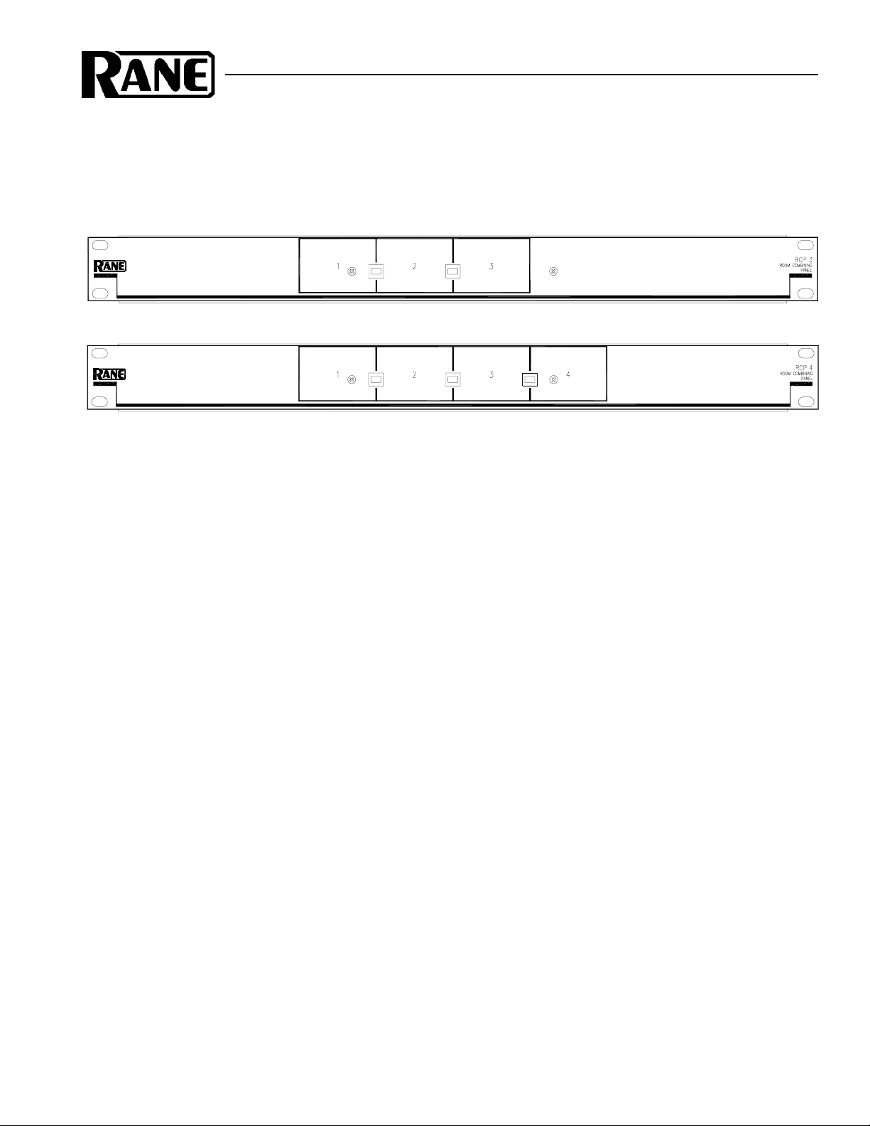
RCP 3
RCP 4
DATA SHEET / MANUAL
RCP 3 and RCP 4
ROOM COMBINING PANELS
General Description
Rane has preprogrammed into the SRM 66 a room
combining mode which makes setting up a 3 or 4 room
combining system a quick task. The RCP 3 (three-room
combining panel) and RCP 4 (four-room combining panel)
are user friendly control accessories for the SRM 66 Splitter
Router Mixer and SR1L Smart Digital Remotes. To create a
room combining system, the installer only has to connect the
RCP 3 (or RCP 4) and 3 (or 4) SR 1L’s to an SRM 66. The
RCP 3 uses Inputs and Outputs 1, 2, & 3 of the SRM 66 for
three rooms. The RCP 4 uses Inputs and Outputs 1, 2, 3 & 4
of the SRM 66 for 4 rooms. See the wiring diagrams on the
following pages.
New versions of the SRM 66 with firmware 2.20 or later
come with preprogrammed room combining systems, so no
additional programming is requiring. Older SRM 66’s may be
upgraded. If the firmware is 2.0 or later, the unit may be
upgraded by replacing one EPROM. If the unit is earlier than
2.0, an EPROM and an EEPROM must be replaced. Contact
the Rane factory for upgrade information.
The RCP 3 and RCP 4 panels mount in a standard 19"
rack and utilize a single rack space.
Operation
Since the RCP 3 and RCP 4 panels show a graphical
representation of the rooms to be combined, operation is very
intuitive. To combine adjacent rooms, the end user simply
pushes the button that straddles the desired rooms. Once the
button’s color becomes green, the rooms are combined. To
uncombine the adjacent rooms, the end user simply re-pushes
the button. The button’s color now becomes black, identifying
the room’s status as uncombined.
Data Sheet-1
RCP 3 and RCP 4 Setup
1. Connect the RCP 3 (or RCP 4) and the SR 1L Remotes to
the SRM 66 as shown on the back page of this data sheet.
2. On the front panel of the SRM 66, use the Page (upper)
Buttons to scroll to the Memory Edit Page:
Mem[n]* Store Recall
Memory [n] Stored! [ n] [ n]
Init
Fact
3. Use the Cursor (lower) buttons to move to Init/Fact.
5. Turn the DATA wheel clockwise until the Init field
becomes RCP.
6. Press the EXE button. A warning screen appears.
7. Press the EXE button again. Another warning screen
appears with prompts.
8. Press the EXE button again (yes this is the 3rd time). In
approximately 10 seconds, the SRM 66 will be in the RCP
Room Combining Mode.
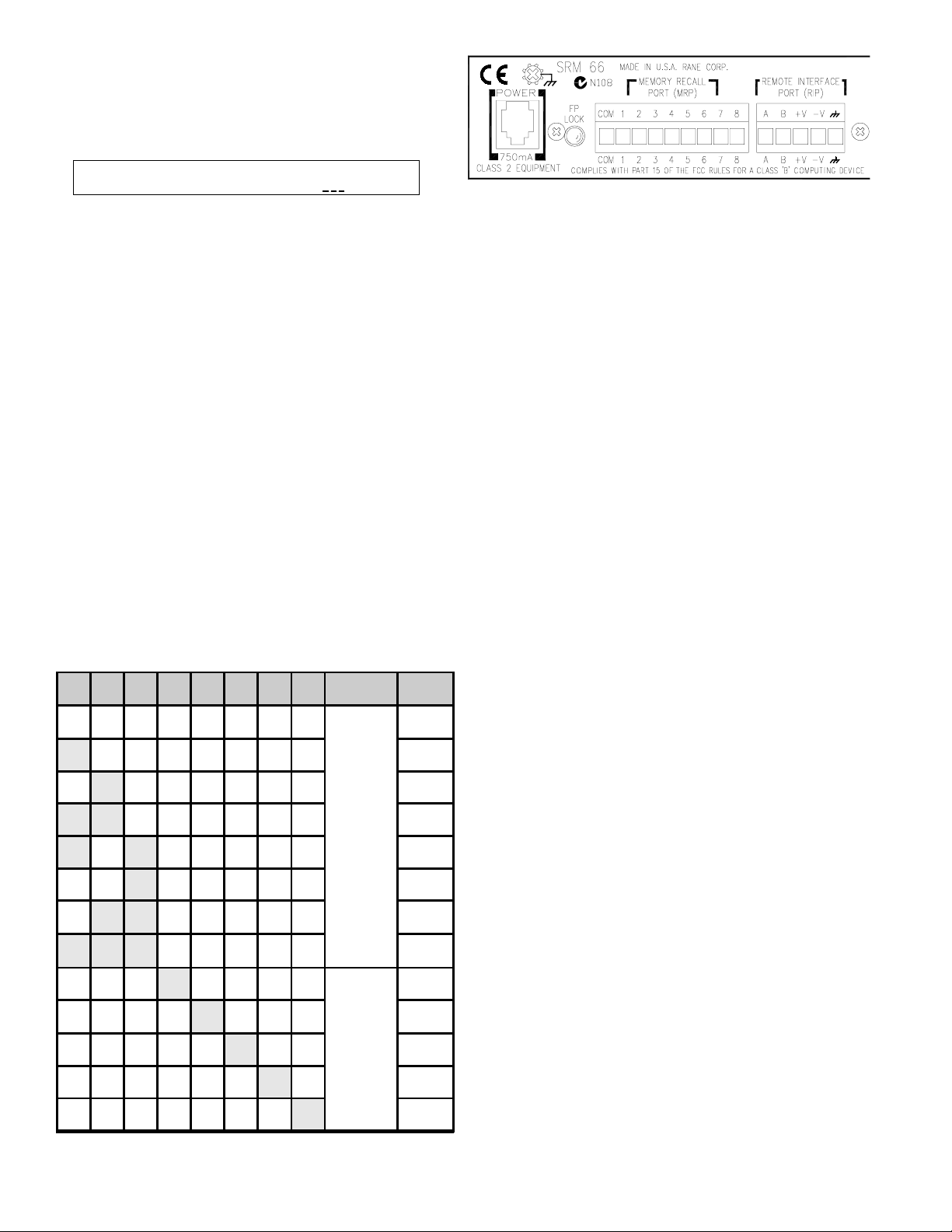
RIP
[SR1]
Memories are recalled by connecting MRP terminals and binary
combinations of terminals to COM.
The RCP (Room Combining Panel) mode
The SRM 66 has 24 Memories. The RCP mode of the
SRM 66 uses the first 8 Memories for the room combining
presets. Memories 9 through 24 are not preprogrammed.
There are 8 MRP (Memory Recall Ports) for recalling
various Memories through contact closures. MRP contacts 1,
2, & 3 have been reserved for room combining presets
(Memories 1-8). MRP contacts 4-8 are programmed to recall
Memories 20-24 when in RCP mode.
The RCP 3 uses MRP contacts 1 & 2, and the RCP 4 uses
MRP contacts 1, 2 & 3. See Table 1 for details.
1 2 3 4 5 6 7 8 Mode Result
00000000
10000000 2
0
1000000 3
1 1000000 4
1
RCP
10 100000 5
00
0
1 1 100000 8
000
0000
00000
000000
0000000
100000 6
1 100000 7
10000
1000 21
10 0 22
10 23
Recalled
regardless
of lower
MRP
closures
124
20
Wiring Connections
When wiring to Euroblocks, a minimum wire gauge of 22
is preferred for reliability. If the ground or shield wire is left
shorter, it acts as a strain relief for the other wires. Cable with
a flexible jacket is easier to use and less likely to damage the
connections. Avoid stripping excess insulation. Inspect wires
for nicks that may lead to wire breakage. Fully insert each
wire in the appropriate socket and tighten the screw. Turn the
power to the unit off until all connections are made.
WIRE TYPES
Variations in wire type do not greatly affect the performance of the remote controls. You may use 3- or 4- conductor
unshielded remote control signal cable for shorter runs (less
than 200 ft.) or 4-conductor (2 pair) shielded remote control
signal cable (use the shield as the GND return) for longer runs
(200 to 1000 ft.). The type of wire required is influenced by
your installation and local electrical codes. Rane Corporation
does not provide or source cable. Please contact your local
retail or wholesale outlet, not the factory.
The following is a short list of suitable cable types:
CONSOLIDATED ELECTRONIC WIRE AND CABLE
Plenum cable:
Unshielded remote control signal cable CAT. #9896
Shielded remote control signal cable CAT. #9877 or #9852
WEICO WIRE & CABLE INC.
Communication and control cable:
Multiconductor, unshielded CAT. #7606
ALPHA
Communication and control cable:
Multiconductor, unshielded CAT. #1175C
BELDEN
Unshielded remote control signal cable CAT. #88741
Shielded remote control signal cable CAT. #88723
Data Sheet-2
Table 1. RCP Binary Control

RCP 3 and RCP 4
ROOM COMBINING PANELS
Room Combine Panel System Design
When designing a Room Combining System, each individual room will have a dedicated single channel mixer, most likely
an EQ of some type, an amplifier channel, and of course some loudspeakers. Room Combining Systems work by combining
adjacent systems together. When rooms need to be combined, the SRM 66 mixes all of the mixer outputs within the combined
zones. In addition, all SR1 L Remote Level Controls within the combined zones will be linked together.
RCP 3 Schematic
123
S2A
2P2T
456
123
S1A
2P2T
456
RCP 4 Schematic
123
S3A
J1
3
2
1
2P2T
S2A
2P2T
S1A
2P2T
456
123
456
123
456
J1A
5
NC
4
3
3
2
2
1
1
C
Data Sheet-3

RCP 3 and RCP 4
ROOM COMBINING PANELS
RCP 3 Room Combining System Wiring
RCP 4 Room Combining System Wiring
RCP 3 and RCP 4 and SRM 66 rear chassis wiring diagrams.
Note that the last SR 1L in each chain must have its TERMINATE switch ON. Set preceding switches to OFF.
©Rane Corporation 10802 47th Ave. W., Mukilteo WA 98275-5098 TEL (425)355-6000 FAX (425)347-7757 WEB http://www.rane.com
Data Sheet-4
All features & specifications subject to change without notice. DOC 105030 PN 12137
 Loading...