

Rane MX 23 User Manual
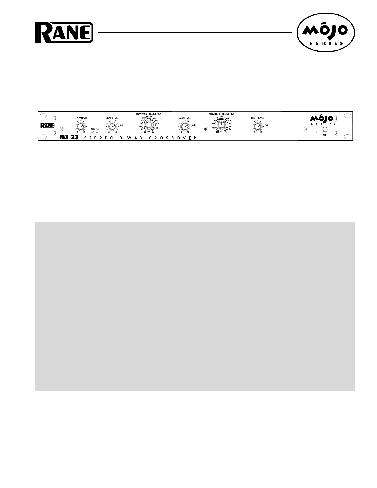
OPERATORS MANUAL MX 23
STEREO 3-WAY CROSSOVER
QUICK START
Whoa, hold on there. Even if you don’t read manuals as a matter of principle, at least read this section to avoid hurting
yourself or your equipment.
Connect the MX 23 with the POWER off. Balanced XLR cables are recommended, but if you must convert to ¼"
connectors, buy or make a cable like the ones on page Manual-11 and keep them as short as possible. This device uses low
impedance balanced line drivers. Do not connect the “+” or “–” output pins to ground, as this may cause the power supply
to shut down. For unbalanced use, leave the unused output pin (“+” or “–”) unterminated.
Consult the speaker manufacturers for the correct crossover FREQUENCY settings. As rugged as some drivers are,
many (especially compression drivers) will not accept frequencies outside of their normal range without producing distortion and possibly self-destruction.
With all equipment turned off and LEVEL controls down, begin making connections to the system as shown on page
Manual-4 or 5. When turning on the system, switch on the power amplifiers last. Now, feed the MX 23 some program
material. Start by turning up the LOW LEVEL, MID LEVEL and HIGH LEVEL to the 0 dB marks. Slowly increase the
INPUT LEVEL, even if it goes all the way to 10, so the +4 dBu (green) light blinks occasionally and the OL (red) light
stays out. This delivers the best signal-to-noise performance.
The MONO SUB OUTPUT is a sum of the Left and Right Low Outputs. The MONO SUB LEVEL adjusts only this
Output and is not affected by the LOW LEVEL control.. When using a single mono bass bin along with stereo mid- and
high-range cabinets, set the 100 Hz FILTER to OUT, allowing the front panel FREQUENCY to control the subwoofer
crossover point. When used with 3-way cabinets and a subwoofer, set the 100 Hz FILTER switch to IN to allow only
frequencies below 100 Hz at this output jack. This way, the MX 23 almost does the job of a Stereo 4-Way crossover, but
without removing that awesome bass from the Left and Right Low Outputs.
WEAR PARTS: This product contains no wear parts.
Manual-1

RISK OF ELECTRIC SHOCK
DO NOT OPEN
CAUTION
IMPORTANT SAFETY INSTRUCTIONS
1. Read these instructions.
2. Keep these instructions.
3. Heed all warnings.
4. Follow all instructions.
5. Do not use this apparatus near water.
6. Clean only with a dry cloth.
7. Do not block any ventilation openings. Install in accordance with manufacturer’s instructions.
8. Do not install near any heat sources such as radiators, registers, stoves, or other apparatus (including ampliers) that produce heat.
9. Do not defeat the safety purpose of the polarized or grounding-type plug. A polarized plug has two blades with one wider than the other. A grounding-type plug has two blades and a third grounding prong. e wide blade or third prong is provided for your safety. If the provided plug does not
t into your outlet, consult an electrician for replacement of the obsolete outlet.
10. Protect the power cord and plug from being walked on or pinched particularly at plugs, convenience receptacles, and the point where it exits from
the apparatus.
11. Only use attachments and accessories specied by Rane.
12. Use only with the cart, stand, tripod, bracket, or table specied by the manufacturer, or sold with the apparatus. When a cart is used, use caution
when moving the cart/apparatus combination to avoid injury from tip-over.
13. Unplug this apparatus during lightning storms or when unused for long periods of time.
14. Refer all servicing to qualied service personnel. Servicing is required when the apparatus has been damaged in any way, such as power supply
cord or plug is damaged, liquid has been spilled or objects have fallen into the apparatus, the apparatus has been exposed to rain or moisture, does
not operate normally, or has been dropped.
15. e plug on the power cord is the AC mains disconnect device and must remain readily operable. To completely disconnect this apparatus from
the AC mains, disconnect the power supply cord plug from the AC receptacle.
16. is apparatus shall be connected to a mains socket outlet with a protective earthing connection.
17. When permanently connected, an all-pole mains switch with a contact separation of at least 3 mm in each pole shall be incorporated in the electrical installation of the building.
18. If rackmounting, provide adequate ventilation. Equipment may be located above or below this apparatus, but some equipment (like large power
ampliers) may cause an unacceptable amount of hum or may generate too much heat and degrade the performance of this apparatus.
19. is apparatus may be installed in an industry standard equipment rack. Use screws through all mounting holes to provide the best support.
WARNING: To reduce the risk of re or electric shock, do not expose this apparatus to rain or moisture. Apparatus shall not be exposed to dripping
or splashing and no objects lled with liquids, such as vases, shall be placed on the apparatus.
NOTE: is equipment has been tested and found to comply with the limits for a Class B digital device, pursuant to part 15 of the FCC Rules. ese
limits are designed to provide reasonable protection against harmful interference in a residential installation. is equipment generates, uses and can
radiate radio frequency energy and, if not installed and used in accordance with the instructions, may cause harmful interference to radio communications. However, there is no guarantee that interference will not occur in a particular installation. If this equipment does cause harmful interference to
radio or television reception, which can be determined by turning the equipment o and on, the user is encouraged to try to correct the interference
by one or more of the following measures:
• Reorient or relocate the receiving antenna.
• Increase the separation between the equipment and receiver.
• Connect the equipment into an outlet on a circuit dierent from that to which the receiver is connected.
• Consult the dealer or an experienced radio/TV technician for help.
CAU T ION: Changes or modications not expressly approved by Rane Corporation could void the user's authority to operate the equipment.
is Class B digital apparatus complies with Canadian ICES-003.
Cet appareil numérique de la classe B est conforme à la norme NMB-003 du Canada.
WARNING
To reduce the risk of electrical shock, do not open the unit. No user
serviceable parts inside. Refer servicing to qualied service personnel.
e symbols shown below are internationally accepted symbols that warn
of potential hazards with electrical products.
is symbol indicates that a dangerous voltage
constituting a risk of electric shock is present within
this unit.
is symbol indicates that there are important
operating and maintenance instructions in the
literature accompanying this unit.
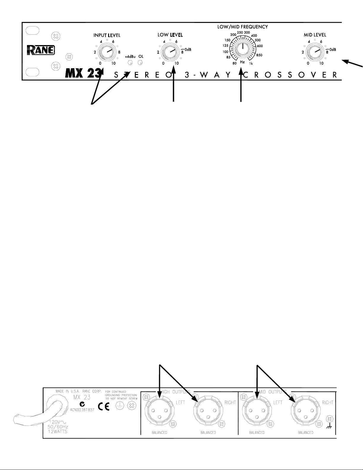
INPUT LEVEL control and
indicators
This controls the overall level without
altering the relative settings of the Low, Mid
and High frequency Outputs. Input gain is
+6 dB at “10”. With signal applied, set this
control so the +4 dBu LED lights occasionally, indicating sufficient signal. Flashing of
the OL (overload) LED during peaks can be
avoided by turning the INPUT LEVEL down.
Cable Wiring
In agreement with IEC and AES/ANSI
standards, Rane wiring convention is pin 2
Positive (hot), pin 3 Negative (cold or
LOW LEVEL control
This controls the level of signal going to the
LOW OUTPUT jacks. Unity gain is reached at
the “0 dB” mark with the INPUT LEVEL set
to “10”. This control does not affect the
MONO SUB OUTPUT level. Refer to Operating
Instructions on page Manual-6.
HIGH OUTPUTS
LOW/MID FREQUENCY control
This 31-position selector sets the crossover
frequency between the Low and MId
frequency Outputs in both Channels. Consult
the manufacturer of the drivers or cabinets
for the correct setting.
return), and pin 1 signal grounded and
chassis grounded (to allow unbalanced
operation). The XLR case is chassis
grounded.
balanced line drivers. Do not connect the
“+” or “–” output pins to ground, as this
may cause the power supply to shut down.
For unbalanced use, leave the unused output
pin (“+” or “–”) unterminated.
Manual-2
This device uses low impedance
These are balanced Output jacks. Connect
the LEFT HIGH OUTPUT to the left channel
input of the high frequency amplifier, and
the RIGHT HIGH OUTPUT to the right
channel input of the high frequency
amplifier. When using different model
amplifiers for the low and high outputs, use
the amplifier with the most wattage for the
low outputs.
MID OUTPUTS
These are balanced Output jacks. Connect
the LEFT MID OUTPUT to the left channel
input of the mid frequency amplifier, and the
RIGHT MID OUTPUT to the right channel
input of the mid frequency amplifier.
 Loading...