

Page 1
OPERATING / SERVICE MANUAL
GRAPHIC EQUALIZERS
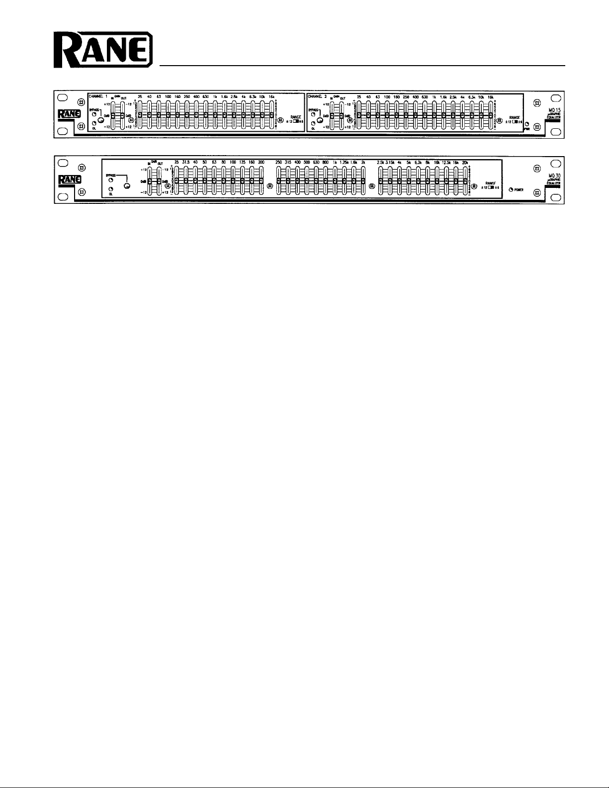
MQ 15/30
QUICK START
Reading this section is a lot like eating spinach. Once you’re through, you can have dessert. So read this spinach, then
devour your MQ dessert.
Hook-up is intuitive. Just follow the silkscreened instructions on the rear of the unit. All three inputs are wired in
parallel (they do not sum); and all three outputs are wired in parallel. Use any ONE input and any or all outputs. Using
the MQ 15/MQ 30 in an Insert Loop of a mixer is extremely easy. Simply connect them together using a single stereo
cable (1/4" TRS) between the mixer’s Insert Loop and the PATCH I/O jack. This jack is wired for the tip=send,
ring=return convention used by many mixer manufacturers. CAUTION: USE EITHER THE PATCH I/O OR ANY OF
THE INPUT AND OUTPUT CONNECTORS — DO NOT USE BOTH AT THE SAME TIME.
Anyone familiar with other graphic equalizers finds the MQ 15/MQ 30 just as familiar. One word of caution: the
boost/cut RANGE switch drastically changes the impact of a given filter. BE CAREFUL.
Setting the IN and OUT GAIN controls to the same physical positions gives unity gain through the equalizer. That is,
moving both slider handles together (keeping them aligned) always maintains overall unity gain from input to output.
Many strange gain structure conditions may be handled with these controls. FOR BEST NOISE PERFORMANCE
ALWAYS POSITION BOTH CONTROLS AS FAR TOWARD THE TOP OF. THE UNIT AS POSSIBLE WITHOUT
LIGHTING THE OL INDICATORS. See the Operating Instructions on the back page for more information, Most
applications require only a few dB of boost or cut. Start with the RANGE switch in the 6dB position and increase to
12dB only if necessary. Setting curves is as easy as it is on all Rane graphics thanks to our unique interpolating constant-
Q circuitry. For more information on setting up your curves correctly, again, see the back page.
NEVER CONNECT ANYTHING EXCEPT AN APPROVED RANE POWER SUPPLY TO THE RED THING
THAT LOOKS LIKE A TELEPHONE JACK ON THE REAR OF THE UNIT. This is an AC input and requires
special attention if you do not have a power supply EXACTLY like the one originally packed with your unit. See the full
explanation of the power supply requirements elsewhere in this manual.
SYSTEM CONNECTION
When first connecting the MQ 15 to other components, LEAVE THE POWER SUPPLY FOR LAST. This gives you a
chance to make mistakes and correct them without damaging your fragile speakers, ears and nerves.
INPUTS. All three inputs are wired in parallel and are actively balanced (true instrumentation amplifiers). Each works
equally well. Choose strictly from a favorite hardware point-of-view, there will be no performance trade-offs. The wiring
convention adheres to American, British and International standards of pin 2 “+”, or tip being hot, pin 3 “–”, or ring being return,
and pin 1, COMMON GND, or sleeve being signal ground. Unbalanced operation involves using only pin 2 “+”, or tip as
signal and pin 1 COMMON GND, or sleeve as ground. It is not necessary to short any terminals or pins to any others. Due
to the true instrumentation nature of the inputs, there is no gain reduction if pin 3, or –,
shorted, it won’t hurt anything either. Use pin 1, the shell, or the COMMON GND point on the barrier strip for shield
ground. (See Rane Note 110 for further information).
OUTPUTS. The outputs mimic the inputs. True balanced output interconnection only requires the use of pin 2 “+”, or tip,
and pin 3 “–”, or ring for signal transmission. It does not require pin 1, or signal ground. The signal exists differentially
between the two balanced leads; ground is not involved. Ground is used only for shielding. Again, have a look at Rane Note
110 for more detail.
is left open; however, if pin 3 gets
(continued on next page)...
Page 2
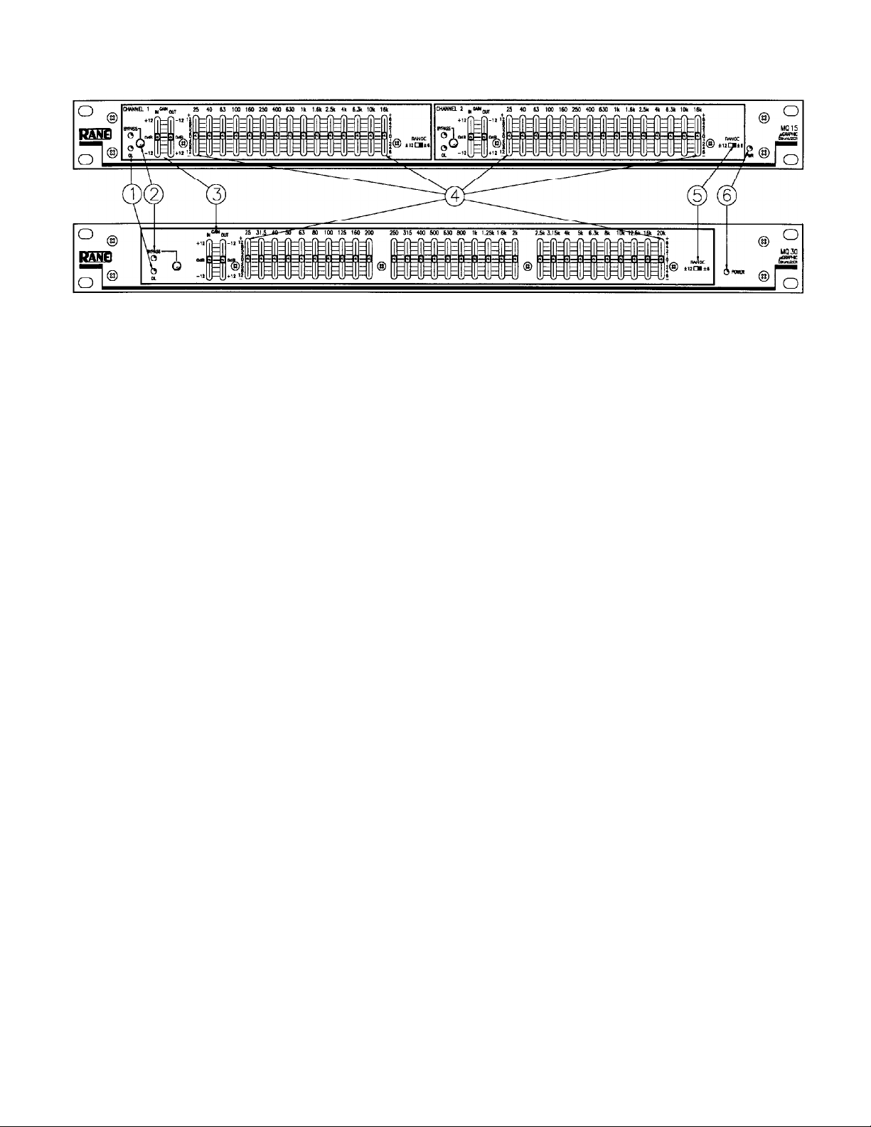
FRONT PANEL DESCRIPTION
1. MASTER OVERLOAD INDICATOR. This red OL LED monitors the input, output and all filter stages for excessive
signal levels. It lights whenever these levels exceed 4dB below clipping. Occasional flickering is normal; however, it
should not be allowed to light steadily.
2. OVERALL BYPASS SWITCH & INDICATOR. This pushbutton switch activates the “hard-wire” bypass function.
When engaged (red BYPASS LED on), all three pins of the input connectors directly connect to the same pins on the
output connectors (hard-wired). Engaging this switch converts the MQ 15/MQ 30 into a relatively expensive patch cord,
but one with pretty lights.
3. INPUT AND OUTPUT GAIN CONTROLS. These slide controls set the relative IN and OUT gain structures. The range
of each control is ±12dB; however, note they are labelled opposite to each other, i.e., the top of the IN control reads
+12dB while the top of the OUT controls reads -12dB. Configured this way, whenever they are held and moved together
the overall gain through the MQ 15/MQ 30 stays at unity. Positioning these controls (together) as far toward the top of
the panel as possible (without lighting the OL indicator) yields the best signal-to-noise performance.
4. FILTER LEVEL CONTROLS. These slide controls set the individual levels of the interpolating constant-Q filters. Their
range is selectable between 6dB (use bottom or right-hand scale) and 12dB (use top or left-hand scale). The grounded
center-detent design of these sliders ensures all filters are off when positioned to their centers.
5. FILTER RANGE SWITCH. Sets the overall range of all sliders between 6dB and 12dB.
6. POWER INDICATOR. This yellow LED lights any time remote power is supplied from either a RS 1 single
power supply or a RAP 10 multiple power supply. Note that this indicator is electrical, not political.
SYSTEM CONNECTION (continued)
EXPANDING. Expanding and/or daisychaining the inputs and outputs normally uses the 1/4" jacks. Three parallel input
connectors allows driving a second signal processor or amplifier without special cabling.
PATCH I/O. The PATCH I/O (Input/Output) jack makes connection to mixer Effects Loop insert points very simple.
Just connect a shielded stereo tip-ring-sleeve (TRS) cable between the PATCH I/O jack and the TRS Effects Loop insert on
your console. (Your mixer must use the tip=send, ring=return Effects Loop wiring convention.)
SIGNAL LEVELS. The MQ 15/MQ 30 is designed for all line-level signals. Signal levels from -10dBV to +4dBu are
considered normal and within range (at least 16dB of headroom exists above these levels). Do not directly connect microphones into the MQ 15/MQ 30. Use a mic preamp (e.g., Rane model MS 1) first.
Page 3

REAR PANEL DESCRIPTION
1. 3-pin INPUT Connector. Pin 2 is positive, pin 3 is negative and pin 1 is signal ground. For unbalanced operation, use pin
2 as hot and pin 1 as return.
2. INPUT Expand Connector. This 1/4" TRS connector parallels the 3-pin connector described above. Tip is positive, ring is
negative and sleeve is signal ground.
3. Terminal Strip Input and Output. The +, –,
pins in the 3-pin and 1/4" connectors. Used for primary inputs and outputs or additional patch connections.
4. OUTPUT Expand Connector. This 1/4" TRS connector parallels the 3-pin connector described above. As before, tip is
hot, ring is not and sleeve is signal ground.
5. 3-pin OUTPUT Connector. Pin 2 is positive, pin 3 is negative and pin 1 is signal ground.
6. PATCH I/O Connector. This 1/4" TRS jack provides an unbalanced I (input) on its tip and an unbalanced O (output) on
its ring. Designed for use with tip=send/ring=return Effect Loop inserts found on many mixing consoles. This provides an
easy means for patching the MQ 15/MQ 30 into Effect Loops as painlessly as possible, using a single 1/4" TRS stereo
patch cable. CAUTION: USE EITHER THE PATCH I/O OR ANY OF THE INPUT AND OUTPUT CONNECTORS —
DO NOT USE BOTH AT THE SAME TIME! THESE ARE NOT SUMMING INPUTS. USE ONLY ONE AT A TIME.
7. GROUND LIFT Switch. This switch provides the ability to separate chassis ground and signal ground. Normally, this
switch should be in the LIFT position. In some circumstances, moving it to the opposite position eliminates stubborn hum
and buzz problems.
If you are tempted to try moving this switch with your power amplifiers turned on and up, DON’T BE. ALWAYS TURN
YOUR AMPLIFIER LEVELS DOWN BEFORE CHANGING YOUR GROUNDS AROUND and then bring them up
slowly.
8. Remote Power Supply Input. The unit is supplied from the factory with a Model RS 1 Remote Power Supply suitable for
connection to this input jack. The power requirements of the unit call for an 18-24 volt AC center-tapped transformer
only.
THIS IS NOT A DC INPUT. IT IS NOT A TELEPHONE JACK.
NEVER USE A POWER SUPPLY WITH YOUR UNIT OTHER THAN THE ONE SUPPLIED OR A REPLACEMENT
APPROVED BY RANE CORPORATION. Using any other type of supply may damage the unit and void the warranty.
and COMMON GND terminals of the barrier strip parallel the respective
9. Chassis Ground Point. A 6-32 screw is used for chassis grounding purposes. See the CHASSIS GROUNDING note on
the last page for details.
Page 4

OPERATING INSTRUCTIONS
Before attempting any equalization of audio with the MQ
15/MQ 30, it is important to optimize the IN and OUT
GAIN control settings. Improper gain distribution is a
common cause of headroom loss and increased noise in
audio systems.
The MQ 15/MQ 30 provides you with an overall BY-
PASS switch & indicator as well as an OL (overload) LED
as useful tools for optimizing this gain set-up. The BYPASS
switch is useful for making quick A-B comparisons, i.e.,
comparing equalized (BYPASS out, LED off) versus
unequalized (BYPASS in, LED on) sound. To do this freely,
without danger of system damage, requires you set the level
through the MQ 15/MQ 30 to approximately unity. Failure to
do so can produce alarming results.
The input and output gain ranges of the MQ 15/MQ 30
go from -12dB to +12dB. The MQ 15/MQ 30 is always unity
gain in bypass, so if you add or reduce gain (beyond EQ
make-up gain) the level differences between BYPASS in/out
can be startling. Therefore you want to set the GAIN
controls for equal in/out loudness levels.
To get started, make the following initial set-up adjustments:
1. BYPASS switch depressed (equals bypassed condition
= red LED on).
2. Both GAIN controls positioned at the top of the panel,
i.e., IN @ +12 and OUT @ -12.
3. All slide controls center-detent positions (0dB boost/
cut).
4. Apply a signal to the system.
5. Check that the OL indicator is not on. If the OL LED
is on, move both GAIN controls down just enough for it to
go out. The MQ 15/MQ 30 stays unity gain from input to
output because you kept both controls at equal settings, thus
ensuring the input is attenuated enough to keep it out of
overload and the output gain is making up for it. For optimum noise performance always take as much gain as
possible through the INPUT stages, i.e., position the IN
GAIN slider as close to +12dB (the OUT GAIN slider
toward -12dB — keep them together) as possible.
6. Release the BYPASS switch and you are ready to start
equalizing the system.
Since acoustic compensation and tone contouring are two
of the most common uses for equalization, here are a few
words on each:
ACOUSTIC COMPENSATION. Acoustic compensation is controlled nicely with a device such as the MQ 15/
MQ 30. The best way to find out what room acoustics are
doing to your sound is to use either a real time analyzer or
any of the many computerized measurement systems such as
time delay spectrometry or other similar devices. This sort of
test equipment lets you analyze the response of the combination of room and sound system and is the only accurate
means available for setting up the MQ 15/MQ 30 properly. If
you are unable to utilize science in this way, your ears will
have to be the judge.
It is a very good idea to always start the equalization
process with the filter RANGE switch in the ±6dB position. It should stay there unless you absolutely cannot
achieve your goal any other way. Then and only then should
you go for the ±12dB position.
Use the BYPASS switch to compare equalized with
unequalized sound. Compare the two and set the equalizer as
best you can using controlled noise sources, sweep signals,
or source material that you are VERY familiar with. Try to
avoid adding too much low end. This is an area where
equalizers are frequently abused, causing lots of unnecessary
stress on amplifiers and speakers. This is particularly
important when using any sort of vented enclosure low
frequency drivers. Too much level applied to a woofer below
the cutoff frequency of its enclosure causes very large
speaker excursions and very short life.
TONE CONTOURING with the MQ 15/MQ 30 is
accomplished mainly by ear. This you know how to do. Be
careful, though, not to introduce too much boost to the upper
bass area (and the sub-bass area as in the last paragraph). Be
aware that the MQ 15/MQ 30 is capable of boosting signals
up to 12dB — a level at which great care should be taken to
prevent seismic disturbances.
IMPORTANT NOTE
CHASSIS GROUNDING
Rane commercial equalizers are supplied with a rear
mounted ground-lift switch. The unit is shipped with this
switch in the “grounded” position, tying circuit ground
to chassis ground. If after hooking up your system it
exhibits excessive hum or buzzing, there is an incompat-
ibility in the grounding configuration between units
somewhere. Your mission, should you accept it, is to
discover how your particular system wants to be
grounded. Here are some things to try:
1. Try combinations of lifting grounds on units that
are supplied with ground lift switches or links.
2. If your equipment is in a rack, verify that all
chassis are tied to a good earth ground, either through
the line cord grounding pin or the rack screws to another
grounded chassis.
3. Units with outboard power supplies do NOT
ground the chassis through the line cord. Make sure that
these units are grounded either to another chassis which
is earth grounded, or directly to the grounding screw on
an AC outlet cover by means of a wire connected to a
screw on the chassis with a star washer to guarantee
proper contact.
Please refer to Rane Note 110 (supplied with your
unit and available on request at no charge if you lose it)
for further information on system grounding.
Rane Corporation 10802 47th Avenue West, Mukilteo WA 98275-5098 TEL (425) 355-6000 FAX (425) 347-7757
All features & specifications subject to change without notice. 520-327 1093
 Loading...