

Page 1

Foreword
Welcome to the MPE Users Guide. Within these
pages lurk the details you’ll need to twiddle every
knob on your Rane MIDI Programmable Equalizer
with full confidence and expertise. If a quick start is
all that you desire, please refer to your MPE Oper-
ating/Service Manual.
The MPE family consists of two models. The
MPE 28 is a one channel, 1/3-octave, 28 band
equalizer. The MPE 14 is a two channel, 2/3-octave,
14 bands per channel equalizer. The MPE 14 and
MPE 28 both feature Rane’s exclusive interpolating
constant-Q filters. Each model is digitally programmable, with equalizer bands adjustable +12dB to
-15dB in 1dB steps, and overall level adjustable
±12dB in 2dB steps. Both models feature 128
permanent memories, comprehensive MIDI implementation, and loads of powerful user functions.
This guide covers the operation, maintenance, and
applications of the entire MPE family.
Rane MPE Users Guide
1
Page 2

About This Users Guide
Conventions
A few words about the various conventions used
in this document:
Front panel LED and key names will be printed
in capital letters and bold typeface.
When pressing the FUNCTION key and an-
other key (OMNI, PRGCHG, KEY, etc.)
simultaneously, we will write this as “ F-KEY
NAME” (for example, F-OMNI). When per-
forming one of these dual key presses, it is
recommended that you press the FUNCTION
key first and hold it in (as if it were a “SHIFT”
key on a typewriter) while you tap the second
key.
Most of the MPE keys and LED’s are given
more than one label. When a key or LED is
specified, only the label relevant to its current
function is used.
Terminology
The term MPE refers to both models of the MPE
family collectively. Since both models are operated
almost identically, this guide will distinguish between individual models only when necessary.
Expression is a feature of the MPE which causes
the current equalizer curve to “bend” with MIDI
continuous controller or channel pressure aftertouch
data. For non-MIDI users, this feature, and all
references to it, may be ignored.
The term equalizer parameters refers to the
individual band levels and the overall level of the
equalizer.
Expression parameters are the individual expres-
sion vectors assigned to each equalizer band, and the
expression controller . These will make more sense
when we discuss them in detail later.
System parameters include the MIDI settings,
and user interface options , such as the MIDI Chan-
nel, bypass status, SYSTEM display numerical
base, and so on.
A Stored Memory refers to one of the 128 per-
manent Stored Memories on board the MPE (you
may have seen other manufacturers use words like
Program, Patch, or Preset in place of our term,
Stored Memory).
Working Memory contains the current equalizer
and expression parameters . Working Memory is
what you hear. Any adjustments to the equalizer are
made directly to Working Memory. Stored Memories receive data from Working Memory. Any time a
Stored Memory or Factory Preset is recalled, it is
placed in Working Memory.
Factory Presets are memories which are supplied
by the factory, and kept in Read Only Memory
(ROM).
A curve is the graphical representation of the
equalizer parameters.
The little square grey and black things on the MPE
front panel are keys. This may seem trivial, but in a
world of keys, buttons, knobs, switches, pushbuttons, actuators, controls, levers, pedals, and so
on, this definition might avoid future embarrassment.
The keys, 100 and 0-9, will often be referred to as
the “number keys” .
Many new terms will crop up as we proceed, but
these should be enough to get us started.
2
Rane MPE Users Guide
Page 3
User Modes and Functions
The MPE user interface is organized into three
main user modes. These are:
Normal Operating mode
EQ Edit mode
Expression Edit mode
Each user mode can be thought of as a drawer
containing a particular set of MPE parameters. To
adjust an MPE parameter, you enter the corresponding mode (i.e., open the drawer), change the parameter, and then exit (close the drawer) when you’re
done.
As implied by its name, the Normal Operating
mode is the mode in which you normally operate the
MPE. Normal Operating mode is entered by the
MPE on power up, and is the mode from which you
enter the EQ Edit and Expression Edit modes. When
you exit either of these latter two modes, you are
returned to Normal Operating mode. Normal Operating mode could also be thought of as “Memory”
mode, since it is the mode in which you recall Stored
Memories, save them, recall Factory Presets, etc. We
will continue to call it Normal Operating mode.
Within the Normal Operating mode, there are 6
equalizer user functions :
Recall a Stored Memory
Store Working Memory
Recall Factory Preset
Set Ramp Step Size
Curve Weighting
Set Lockout Status
and 8 MIDI user functions:
Set MIDI Channel
Program MIDI Map
Enable OMNI Mode
The EQ Edit and Expression Edit modes provide
the environments for you to edit the equalizer and
expression parameters, respectively.
The EQ Edit mode provides two user functions in
addition to the equalizer editing interface:
Compare
Clear (set to 0dB) Bands
Expression Edit mode provides a simple interface
to the expression parameters.
User functions must be accessed from the correct
mode. This is the most important concept for intuitive operation of the MPE. For example, if you want
to flatten the equalizer bands, you must be in the EQ
Edit mode to access this function. Similarly, you
must be in the Normal Operating mode to recall a
Stored Memory, set a MIDI parameter, and so on. If
you attempt to access a user function from the wrong
mode, the MPE hurls error messages into in the
SYSTEM display.
Entering user modes and functions is accomplished by pressing the key assigned to them. Each
key is identified on the front panel. You never have
to search through a hierarchy of hidden menus to
find them. (You’re welcome.)
You can usually enter the Normal Operating mode
simply by pressing the MEMORY key. The word
usually is stressed because there are two exceptions.
In EQ Edit mode you must press the EQ key until
the EQ LEDs are off to reach Normal Operating
mode (since the MEMORY key is used for the
compare function). In the Program MIDI Map
function you might have to press the MEMORY
key twice.
Entering EQ Edit mode is no big deal. Just hit the
EQ key. That’s it. Entering the Expression Edit
mode is just as easy, press the EXPRESS key.
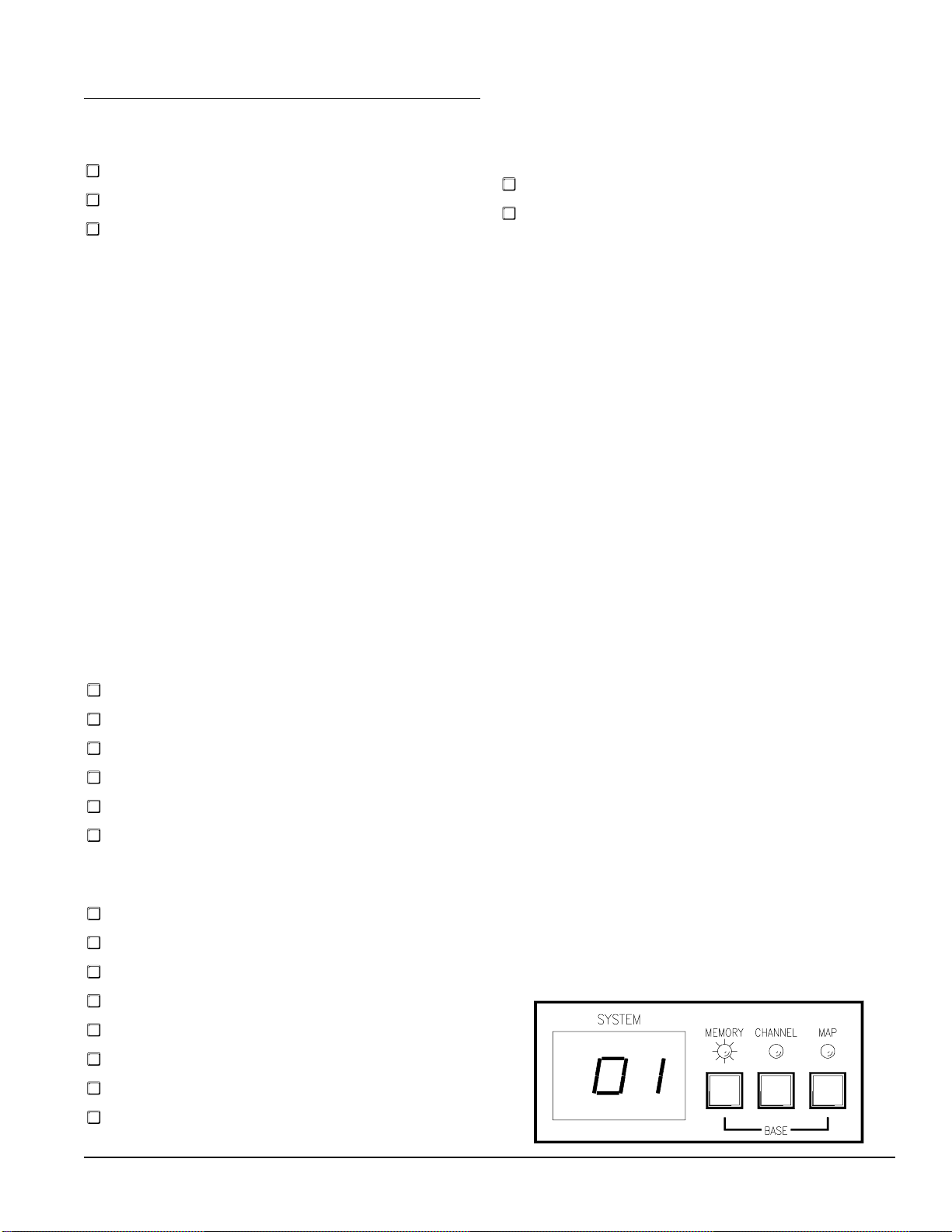
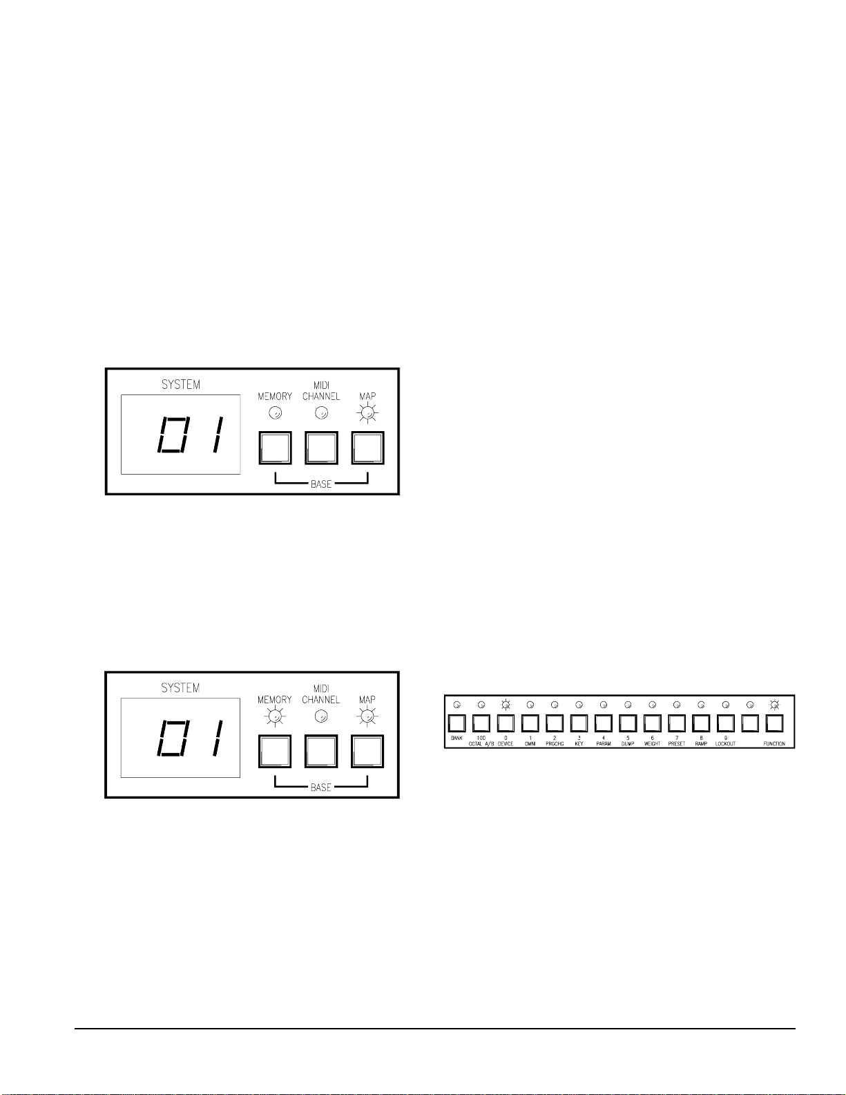
So how can you tell which user mode you’re
currently in? If you’re in the Normal Operating
mode, the SYSTEM display area on the right side of
the MPE front panel will look something like:
Enable Program Change Output
Enable Key Scan Echo
Enable Parameter Echo
Set Device ID
Dump Memory
Rane MPE Users Guide
3
Page 4
Notice that the MEMORY LED is lit, and the
SYSTEM display has some sort of number in it.
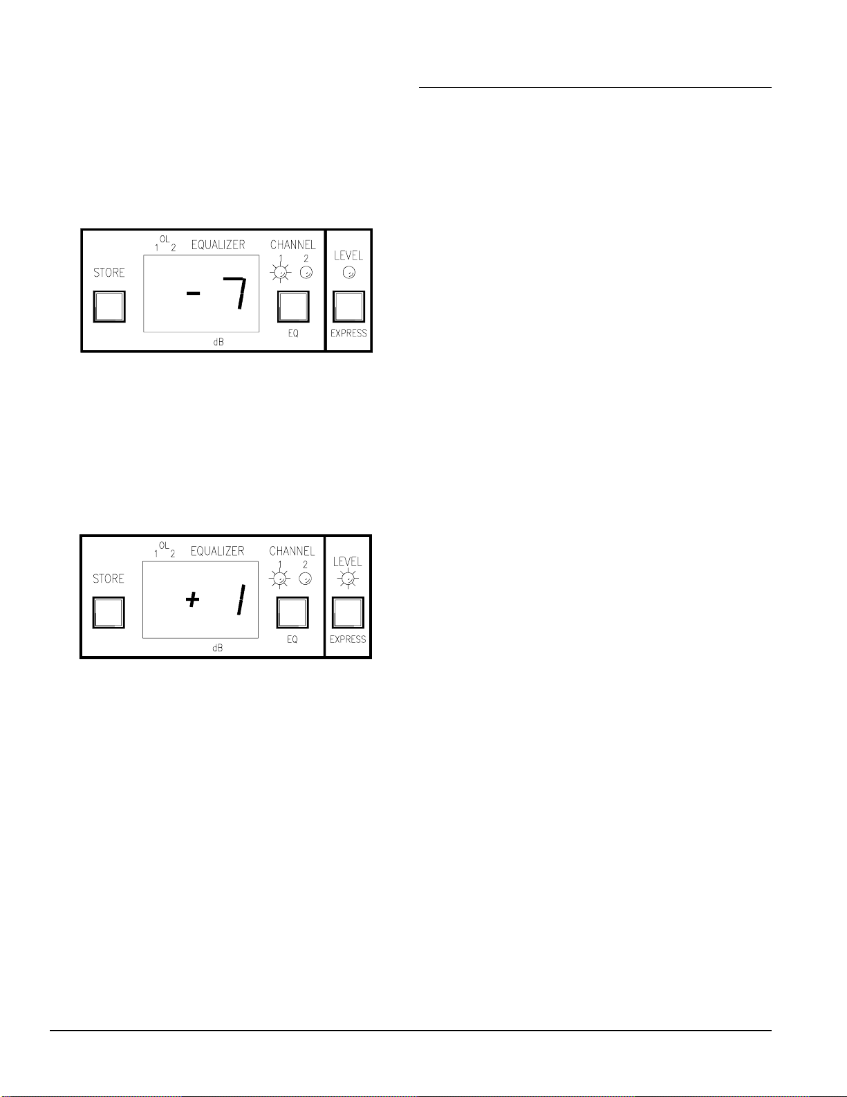
The EQ Edit mode can be recognized by the LEDs
above the EQ button. If either of these LEDs is lit,
(and not flashing) then you are in EQ Edit mode.
The following figure shows what the MPE 14 looks
like after a band is selected, the MPE 28 has a
similar appearance:
In the above example the MPE 14 is in Channel 1
EQ Edit mode, as shown by the CHANNEL 1 LED
and number in the EQUALIZER display.
Expression Edit mode is recognized if the EX-
PRESS LED is lit, and any of the LEDs above the
EQ key are flashing. On the MPE 14 it looks some-
thing like:
Detailed Operation
It’s time to roll up your sleeves and get your hands
dirty. If you haven’t already done so, plug in your
MPE, grab a fresh can of your favorite sudsy beverage, and feed some tunes through the equalizer.
We are about to discuss each user function in full
detail, one by one. The order in which we proceed
follows a normal session of recalling a curve from
Stored Memory, editing the parameters, comparing
these parameters to what we started with (Stored
Memory), and writing this new curve to Stored
Memory.
Once we master these elementary operations,
we’ll adjust the ramp step size, recall a few Factory
Presets, edit the expression parameters, do some
curve weighting and copying, and place the MPE in
lockout.
The final discussion brings us into the world of
MIDI. First, we’ll set the MIDI Channel, OMNI
mode, and Program Change Output options, program the MIDI map, and then set the Device ID,
discuss Key Scan Echo and Parameter Echo, and
dump memory to a remote device.
When you are in a user function within one of
these modes, the displays may look different. As we
describe each user function in detail, we will explain
what the displays show.
Bypass is the one user feature that transcends all
three user modes. You can place the equalizer in
bypass in any function in any mode at any time by
pressing the BYPASS key(s). Pressing this key
again removes the equalizer from bypass.
With the distinction between user modes and
functions in mind, we now proceed with detailed
operation of the MPE.
Recalling Curves From Stored Memory
The most basic function of the MPE is to transfer
Stored Memories to Working Memory. To recall a
Stored Memory, you must tell the MPE which one
you want. That’s it. Here are the play-by-play
details:
1. Make sure you’re in Normal Operating mode.
Normal Operating mode is active if only the
MEMORY LED is lit, and the SYSTEM display
has a non-flashing number in it. If you’re not in
Normal Operating mode, then jump out of whichever mode or function you are in (since Normal
Operating mode is home base, you will always
return here from all other modes).
2. Enter the number of the Stored Memory you wish
to recall. Use the keys labeled with numbers 100,
0-9 below them. Numbers are entered tens digit
first, ones digit second. If the number is less then
10, you must type in a leading 0. If the number is
100 or greater, press the 100 key before the tens
and ones digits keys.
4
Rane MPE Users Guide
Page 5
That’s all. The Stored Memory corresponding to
the number you just typed in is immediately transferred to Working Memory. The rate at which the
equalizer changes to these new parameters is determined by the ramp step size (more on this later).
There are three variations to the process described
above. These involve the bank hold/release option,
the octal/decimal numerical base option, and scrolling with the UP and DOWN keys. Let’s take a look
at each in detail.
Bank Hold/Release
The above process of entering a number requires
two key presses for numbers between 01-99, and
three key presses for numbers 100 and above. The
bank hold option allows you to freeze the hundreds
and tens digits of the current number, and enter new
numbers by selecting only the ones digit. This
enables recall of any of ten different Stored Memories with one key press.
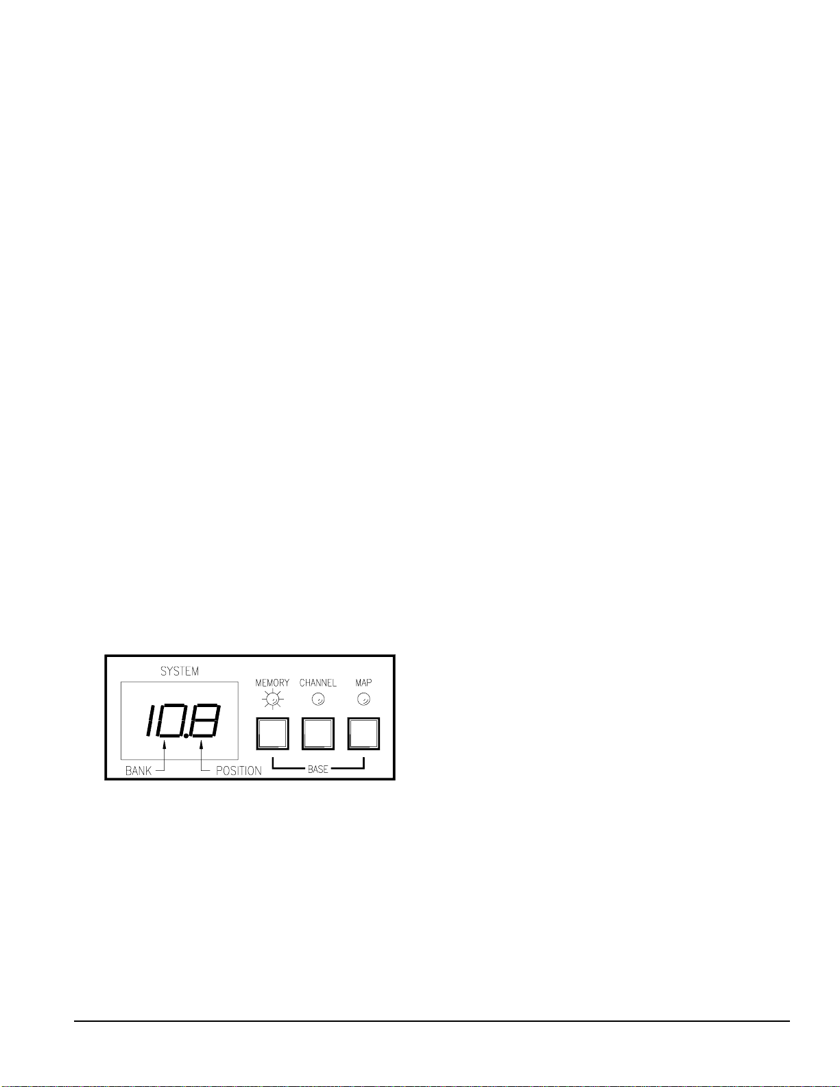
When the BANK key is pressed, the decimal
point to the immediate right of the tens digit in the
SYSTEM display illuminates. The digits to the left
of the decimal point (hundreds and tens) determine
the current bank. The digit to the right (the ones
digit), is the position pointer (see the figure below).
Within the held bank, you choose new positions by
pressing one key ( 0-9). There are ten possible positions within any bank (except for bank 12, which has
9 positions: 12.0- 12.8).
Selecting The SYSTEM Display Base
Remember when your sadistic high school math
teacher made you perform impossible arithmetic in
different numerical bases? Well, Freddy Krueger
returns… Actually, this option is provided to clear
up the confusion that arises when your MIDI devices
hurl decimal and octal numbers at each other, and
expect you to sort out the mess.
If you are leery about the differences between the
decimal and octal numerical bases, please visit the
side bar on the following page.
To toggle the numerical base of the SYSTEM
display, press and hold the MEMORY key and then
tap the MAP key. Voila! You’re now looking at the
same number as before, but in the opposite base.
Tip: Be careful to press the MAP key after the
MEMORY key, and release it before the
MEMORY key. If you don’t, the MPE pops you
into the Program MIDI Map function. If this happens, hit the MEMORY key twice to re-enter
Normal Operating mode.
Number entry for octal is similar to decimal, with
two basic differences. First, only the numerals 1-8
are used. If you press the 0 or 9 keys in octal mode,
you will be scolded by the MPE. The second difference is the 100 key now assumes the role of OC-
TAL A/B (see the side-bar on the next page if you
don’t know A from B ). Pressing OCTAL A/B
toggles the third digit of the octal number between
groups A and B. Experiment with the two bases for
awhile, you’ll see how it works.
Pressing the BANK key a second time releases the
current bank, returning you to normal number entry.
Note: Anytime you change to a different user
mode or function, the bank releases automatically.
As an example, say you just recalled Stored Memory
108. If you press the BANK key, you will get the
display shown above. Now, if you press any of the
number keys (0-9), you will instantly access Stored
Memories 100- 109. Pressing the BANK key
again releases the bank, turning off the decimal point
and returning you to normal number entry.
Rane MPE Users Guide
Scrolling Through Stored Memories
With The UP and DOWN Keys
If you wish to recall the next or previous Stored
Memory, press the UP or DOWN key to increment
or decrement the current Stored Memory number in
the SYSTEM display. Holding either key down for
a prolonged period causes the MPE to scroll through
Stored Memories. If the bank is held, only the ones
digit scrolls (i.e., in our earlier bank hold example,
you scroll through numbers 100- 1 01- 1 02…
109- 100 and so on).
So, we’ve now recalled a Stored Memory, in
either the decimal or octal format, with the bank held
or released. The contents of the recalled Stored
Memory occupy Working Memory. Let’s change the
equalizer parameters…
5
Page 6

The Secrets of Decimal and Octal Numbers
The concepts behind decimal and octal numbers may be intimidating at first, but are really very
simple. People count in base ten (decimal) because they have ten fingers and toes. A chicken has three
toes on each foot, and would therefore naturally count in base six (if it used both feet). Snakes don't have
toes, that's why they can't count. Anyway, ten is a very special number to us humans. When we count,
we organize our numbers into groups of ten so we can tally them up with our fingers.
The decimal numbering system starts with 0, goes to 9, and then recycles to 0 again—with the ten's
digit incremented by one. We continue this until the ten's digit hits 9, recycles to 0 and the hundred's
digit increments by one. This goes on forever, in groups of ten.
Octal numbers have one major difference from decimal numbers. Each digit is recycled with every
count of eight, instead of ten. Octal numbers therefore look something like: 00, 01, 02, 03, 04, 05, 06,
07, 10, 11, 12, 13, 14, 15, 16, 17, 20, 21…
There's an added twist. MIDI octal numbers usually use the symbols 1-8, instead of 0-7, to represent
the eight numerals. So MIDI octal numbers are sequenced: 11, 12, 13, 14, 15, 16, 17, 18, 21, 22-28, 3138, 41-48, and so on. That's all there is to it. If a decimal MIDI device sends number 10 to an octal MIDI
device, the octal device will proudly display the number 22. These are really the same number (i.e.,
they're the tenth number in their respective sequences), they are just written differently.
One final detail. A two digit MIDI octal number has a decimal equivalent maximum value of 64 (i.e.,
MIDI octal 88 = decimal 64). If we want to represent numbers up to decimal 128, then we need a third
octal digit (the 64's digit). Rather than using a 1 or 2 for this purpose, MIDI octal typically uses an A or
B to signify the group. Group A is the lower 64 numbers, group B is the upper 64 numbers.
Editing The Equalizer Parameters
Changing the parameters in Working Memory
couldn’t be easier (yeah, right). You simply enter the
EQ Edit mode, select a band or overall level, and
adjust this parameter up or down (boost or cut). The
key presses necessary to carry this out vary slightly
between each MPE model. We examine each separately.
MPE 14 Editing:
1. Make sure you’re in the Normal Operating mode
and then enter the EQ Edit mode by pressing the
EQ key. Pressing the EQ key once selects Chan-
nel 1 of the equalizer, twice selects Channel 2,
thrice accesses both channels in stereo (allowing
you to edit both channels simultaneously), and a
final press brings you full circle back to Normal
Operating mode. The CHANNEL 1 and/or
CHANNEL 2 LEDs corresponding to the selected equalizer Channel(s) illuminates, and a
cursor flashes in the EQUALIZER display.
2. Select a band (40Hz-16kHz) or overall level by
pressing its key ( 40-16k, or LEVEL). The LED
associated with this parameter lights. The
parameter’s current value appears in the
EQUALIZER display.
3. Press the UP or DOWN key to boost or cut the
selected parameter.
4. Repeat steps 1-3 until all changes are complete.
5. Press STORE to enter the Store function and
save your changes, or EQ to return to Normal
Operating mode. If you chose to store your new
parameters, skip down to the Storing Working
Memory section for further instructions.
Note: Implementing step 2 while editing both
Channels simultaneously causes the MPE 14 to copy
the original Channel 1 parameter to Channel 2.
Subsequent changes to this parameter are made to
both Channels. To copy all of Channel 1’s equalizer
parameters to Channel 2, enter Edit Both mode and
run your finger along all the EQ buttons ( LEVEL,
40-16k).
MPE 28 Editing:
1. Make sure you’re in the Normal Operating mode
and then enter the EQ Edit mode by pressing the
EQ key. Pressing the EQ key once selects the
6
Rane MPE Users Guide
Page 7

lower frequency bands (31.5-630 Hz) of the
equalizer. Pressing EQ again selects the upper
frequency bands (800-16 kHz). Pressing EQ a
third time returns you to Normal Operating mode.
The LED corresponding to the group of bands
you choose illuminates, and a cursor flashes in
the EQUALIZER display.
2. Select a band or overall level by pressing its key
(31.5-16k, or LEVEL). The LED associated with
this parameter lights. The parameters current
value appears in the EQUALIZER display.
3. Press the UP or DOWN key to boost or cut the
selected parameter.
4. Repeat steps 1-3 until all changes are complete.
5. Press STORE to enter the Store function and
save your changes, or EQ to return to Normal
Operating mode. If you chose to store your new
parameters, skip down to the Storing Working
Memory section for further instructions.
Once a curve has been altered, the MEMORY
LED flashes indicating that Working Memory no
longer matches the Stored Memory shown in the
SYSTEM display. This is your cue to store these
changes before recalling a new Stored Memory (in
which case the Working Memory parameters are
overwritten and lost if not stored somewhere).
There are two additional user functions that you
can invoke while editing the equalizer parameters.
These are compare and clear.
Comparing Working Memory To Stored
Memory
You can always compare two Stored Memories
when you’re in the Normal Operating mode simply
by recalling them to Working Memory and listening
to the difference. If they are two consecutive memories, then the UP and DOWN keys are all that is
required. Otherwise you have to type in their numbers.
While you are in the EQ Edit mode, you can
audibly compare the contents of Working Memory
to the Stored Memory shown in the SYSTEM
display. This allows you to perform A-B comparisons between the original and altered curves.
To activate the compare function, press and hold
the MEMORY key while in the EQ Edit mode. You
now hear the contents of the Stored Memory. A
letter “CC” occupies the EQUALIZER display
Rane MPE Users Guide
verifying the compare function.
When you release the MEMORY key, Working
Memory returns to the equalizer. You can compare
anytime during the edit process.
Operating The Clear Command
Simultaneously pressing the UP and DOWN keys
while in the EQ Edit mode clears the parameter
under edit to 0dB. If you haven’t chosen a band or
overall level (i.e., you haven’t implemented step 2 of
the above editing instructions) the entire Channel is
cleared.
Once the clear command is activated, a 00 appears
in the EQUALIZER display and the LED(s) corresponding to the affected parameter(s) turns on for
one second to verify the operation.
Storing Working Memory
Now that you’ve recalled a curve and changed it,
you will want to save it. This is accomplished with
the Store function.
The Store function transfers the parameters in
Working Memory to a specified Stored Memory.
Once the transfer is complete, you are returned to
Normal Operating mode.
Here is the play-by-play action:
1. Press STORE to enter the Store function. (You
may have already done this, as instructed in the
editing instructions above.) Once you are in the
Store function, the SYSTEM display flashes with
the default (current) Stored Memory location.
2. Enter a different Stored Memory number, if
desired, using the number keys. The SYSTEM
display will continue to flash. You can also use
UP or DOWN to scroll through Stored Memory
numbers.
3. Once you’ve selected the proper Stored Memory
number, press STORE again to complete the
transfer and return to Normal Operating mode. If
you change your mind, press MEMORY to
return to Normal Operating mode without storing.
The SYSTEM display stops flashing.
Hey—guess what? You now know everything
there is to know about recalling a curve, changing it,
and sending it to a Stored Memory. Congratulations.
Take some time out to practice this for awhile, and
then we will resume our discussion with some more
advanced user operations…
7
Page 8

Adjusting The Ramp Step Size
One of the unfortunate laws of physics tells us that
abrupt changes to audio signals cause “pops”. The
bigger the change, the worse the pop. To combat this
nemesis, the MPE ramps between curves, with a
programmable step size. The slope of this ramp
determines how much of a pop is output by the
equalizer. The steeper the slope, the faster the
change, and therefore—the louder the pop.
The ramp step size is programmed in dB values. A
ramp step size of 1dB forces the MPE to change
each band and overall level in 1dB increments, as it
recalls a new equalizer curve. This corresponds to
the most gradual change. A value of 27dB causes the
MPE to change with 27dB steps (the most rapid
change). If the ramp step size is larger than the
required change, the change is executed in one step.
If the ramp is set for 1dB steps, and a lot of bands
are changed, it takes longer to recall the new curve
than if the ramp is set for larger steps. This is the
result of having to make many small steps to ramp
up to the new values. You may wish to take advantage of this feature to create “crossfades” between
curves. (For details concerning ramp timing see
Appendix B.)
Setting the ramp step size is easy:
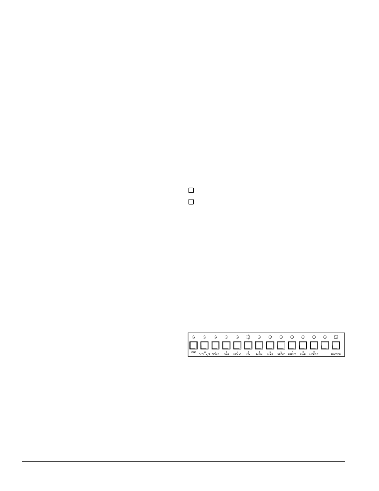
1. Starting from the Normal Operating mode, enter
the Set Ramp function by pressing F-RAMP. The
FUNCTION LED illuminates, and the RAMP
LED flashes to verify your safe arrival in the Set
Ramp function (see the figure below). The SYS-
TEM display shows the current ramp value.
2. Enter the ramp step size ( 01-27) using the number
keys, or by pressing UP or DOWN.
Recalling Factory Presets
Deep inside the MPE, nestled in ROM, are powerful Factory Presets. Many of these presets have been
prepared by notable professionals, giving you the
opportunity to experiment with curves used by the
pros. The particular Factory Presets in your model
are listed in Appendix D .
Factory Presets must be recalled to Working
Memory, they can not be copied directly to Stored
Memory. You may recall one Factory Preset at a
time, and then optionally transfer it to a Stored
Memory.
To recall a Factory Preset to Working Memory,
perform the following steps:
1. Make sure you’re in Normal Operating mode, and
then enter the Recall Factory Preset function by
pressing F-PRESET . The FUNCTION LED
illuminates, and the PRESET LED flashes to
verify entrance to the Recall Factory Preset
function (see the figure below). The SYSTEM
display shows the default Factory Preset.
2. Enter the number corresponding to the Factory
Preset you wish to copy to Working Memory (if
it is different from the default) using the number
keys.
3. Press F-PRESET to complete the transfer, or
press MEMORY to abort the recall and return to
Normal Operating mode. The FUNCTION and
PRESET LED’s extinguish.
The Factory Preset has been transferred to Working Memory. You are free to edit its parameters as
usual, and send it to Stored Memory.
3. Press F-RAMP to return to Normal Operating
mode. The FUNCTION and RAMP LEDs turn
off.
8
Rane MPE Users Guide
Page 9

Editing The Expression Parameters
Expression is a feature of importance to musicians
who use MIDI continuous controllers or channel
pressure aftertouch. Expression assigns a vector
(direction) to each band of the MPE, and specifies a
MIDI continuous controller or channel pressure
aftertouch to act as the expression controller.
When the assigned expression controller sends
MIDI data to the MPE, the current equalizer parameters boost, cut, or remain unchanged depending on
the direction of each band’s vector. The amount of
boost or cut is relative to the magnitude of the
expression controller. If the expression controller is
at full scale, the equalizer band(s) will be boost or
cut 15dB.
Expression offers the musician a new tool. By
programming the expression vectors, any possible
bend or twist to the equalizer curve can be achieved.
Try setting the low end to boost and high end to cut
to get a thundering effect, or add some presence to
vocals by boosting the midrange. The possibilities
are unlimited.
To adjust the expression parameters for the MPE
14, perform the following procedure:
1. Make sure you’re in Normal Operating mode, and
then enter Expression Edit mode by pressing the
EXPRESS key. Pressing EXPRESS once selects
Channel 1, twice selects Channel 2, three times
selects both simultaneously, and a fourth time
returns you to Normal Operating mode. The
EXPRESS LED illuminates, and the CHAN-
NEL 1 and/or CHANNEL 2 LED(s) flashes to
verify your entry to the Expression Edit mode. A
cursor flashes in the EQUALIZER display and
the current expression controller is displayed in
the SYSTEM display.
2. Press the UP or DOWN keys to scroll to the
desired expression controller. Any single MIDI
continuous controller number (0-120) may be
selected. Scrolling past number 120 selects
Channel Pressure Aftertouch (displayed as
aftaft), or all controllers and aftertouch (displayed as allall).
A third option is the auto-detect feature (dis-
played as detdet). You may scroll to this option,
or access it directly by pressing the UP and
DOWN keys simultaneously. Auto-detect forces
the MPE to assign the next received MIDI continuous controller as the expression controller.
This is useful if you aren’t sure what number a
particular controller is assigned to. Once you
have the detdet option in the SYSTEM display,
send a message from the unknown MIDI continuous controller and the MPE automatically assigns
that controller number to the expression controller.
A final option is offoff which disables the expres-
sion function. Scrolling past offoff brings you full
circle to continuous controller number 00.
3. Select a frequency band by pressing its key. The
current vector direction is displayed in the
EQUALIZER display. The display shows +1+1
for an upward (boost) vector, -1 -1 for a downward
(cut) vector, and 0 0 for a flat vector. Remember,
bands with upward vectors boost relative to the
magnitude of the received expression controller,
bands with downward vectors cut. Bands with flat
vectors will not change.
4. Press the same band key to toggle the vector
between +1+1, -1-1, and 00.
5. Repeat steps 1-4 until all desired vectors are
programmed.
6. Press STORE to enter the Store function, or
EXPRESS (1-3 times) to return to Normal
Operating mode.
If you chose to store your new parameters, refer
back to the Storing Working Memory section for
further instructions. Remember, if you don’t store
your changes, you will lose them next time you
recall a new Stored Memory or Factory Preset.
Adjusting MPE 28 Expression Mode parameters :
1. Make sure you’re in Normal Operating mode, and
then enter Expression Edit mode by pressing the
EXPRESS key. Pressing EXPRESS once selects
the lower frequency bands (31.4 Hz-630 Hz),
twice selects the upper frequency bands (800 Hz16 kHz), and a third time returns you to Normal
Operating mode. The EXPRESS LED illuminates, the upper or lower row LED flashes, and a
cursor flashes in the EQUALIZER display
indicating you are now in Expression Edit mode.
The current expression controller is displayed in
the SYSTEM display.
Rane MPE Users Guide
9
Page 10

2. Press the UP or DOWN keys to scroll to the
desired expression controller. Any single MIDI
continuous controller number ( 0-120) may be
selected. Scrolling past number 120120 selects
channel pressure aftertouch (displayed as aftaft),
or all controllers and aftertouch (displayed as
allall).
A third option is the auto-detect feature (dis-
played as detdet). You may scroll to this option,
or access it directly by pressing the UP and
DOWN keys simultaneously. Auto-detect forces
the MPE to assign the next received MIDI continuous controller as the expression controller.
This is useful if you aren’t sure what number a
particular controller is assigned to. Once you
have the detdet option in the SYSTEM display,
send a message from the unknown MIDI continuous controller and the MPE automatically assigns
that controller number to the expression controller.
A final option is offoff which disables the expres-
sion function. Scrolling past offoff brings you full
circle to continuous controller number 00.
3. Select a frequency band by pressing its key. The
current vector direction is displayed in the
EQUALIZER display. The display shows +1+1
for an upward (boost) vector, -1-1 for a downward
(cut) vector, and 00 for a flat vector. Remember,
bands with upward vectors boost relative to the
magnitude of the received expression controller,
bands with downward vectors cut. Bands with flat
vectors will not change.
4. Press the same band key to toggle the vector
between +1+1, -1-1, and 00.
5. Repeat steps 1-4 until all desired vectors are
programmed.
6. Press STORE to enter the Store function, or
EXPRESS to return to Normal Operating mode.
If you chose to store your new parameters, refer
back to the Storing Working Memory section for
further instructions. Remember, if you don’t store
your changes, you will lose them next time you
recall a new Stored Memory or Factory Preset.
Curve Weighting
Sometimes the need to combine two or more
equalization curves arises. In the old days of analog
graphic equalizers, you were forced to either cascade
several units, each adjusted with one of the curves,
or tweak the sliders on one equalizer to manually
derive the sum of the curves. The MPE 14 and MPE
28 provide a curve weighting function that puts
these cumbersome methods to rest.
With the MPE curve weighting operation, you
may add two curves in the MPE together. One curve
is always in Working Memory, the other is a specified Stored Memory.
One problem can arise when adding two curves.
For example, if each of two curves has 1kHz boosted
+10dB, their sum at 1kHz equals +20dB. The MPE
allows a maximum of 12dB boost. Oops. Fortunately, the MPE is smart. If the resultant curve is out
of range, the entire curve shifts up or down to
accommodate the curve.
An example is in order. Say we add two curves
with the following parameters:
Level 50 125 315 800 2k 5k 12.5k
Curve 1: 0 6 7 4 -3 0 8 2
Curve 2:
Sum: 0 12 13 10 3 8 16 10
0 6 6 6 6 8 8 8
As you can see in the above table, the sum of the
two curves goes out of range at 125Hz and 5kHz. At
this point we have two options. First, we can simply
truncate the out of range bands to +12dB. This
works fine, but penalizes us unnecessarily. The more
elegant option shifts the entire curve down so the out
of range bands come back in range. In the above
example, the sum is shifted down 4dB so the 5kHz
band becomes +12dB. This results in the curve:
Level 50 125 315 800 2k 5k 12.5k
Sum: 0 8 9 6 -1 4 1 2 6
The curve is now entirely within range. Since we
shifted the curve down by 4 dB, the overall gain of
the unit has been reduced by 4 dB. We can take
advantage of the overall level adjustment to compensate for this, resulting in the curve below:
10
Level 50 125 315 800 2k 5k 12.5k
Sum: 4 8 9 6 -1 4 1 2 6
Rane MPE Users Guide
Page 11
The overall level adjustment has its own minimum
and maximum values. There is a limit then, to how
far this curve shifting can go before running out of
room. If you know the resultant curve requires
overall level compensation ahead of time, make sure
the overall level is capable of supporting this change.
The above curve is the final result of the curve
weighting algorithm.
What happens if we have both over and under
ranges? For example:
Level 50 125 315 800 2k 5k 12.5k
Sum: 0 4 13 -6 -26 4 0 6
To perform curve weighting on the MPE 14:
1. Make sure you’re in Normal Operating mode, and
then enter the curve weighting function by pressing F-WEIGHT . The FUNCTION LED illuminates, and the WEIGHT LED flashes to verify
that you’re in the curve weighting function (as
shown in the figure below). The SYSTEM
display shows the default Stored Memory which
will be added to Working Memory.
The above curve has an over-range at 125Hz and
an under-range at 800Hz. The MPE performs an
optimized curve weighting algorithm on this curve.
The optimization shifts the curve up or down until
the sum of all over ranges is equal to the sum of all
under ranges. Once this is accomplished, the remaining out of range bands are truncated to +12dB or 15dB. For the above example, we obtain the following curve:
Level 50 125 315 800 2k 5k 12.5k
Pretruncation
Sum:
Posttruncation
Sum
-6 9 18 -1 -21 9 5 11
-6 8 12 -1 -15 9 5 11
The curve is shifted up 5dB so that the over range
at 125Hz and the under range at 800Hz both equal
6dB. Notice that the overall level was compensated
with -6dB instead of -5dB. This is because overall
level can only be adjusted in 2dB increments. The
final weighted curve could be 1dB off in overall
gain, but who’s complaining? Also notice the final
truncation of out-of-range bands once the curve is
shifted to its optimal position.
In most cases you don’t have to worry about how
the MPE is performing this optimization process. It
is perfectly happy to carry out all these tedious
computations on its own. All you need to do is feed
it Working Memory and a Stored Memory. If you
want to weight two curves in Stored Memory, you
must first recall one of them to Working Memory.
Likewise, to weight a Factory Preset with a Stored
Memory you must first recall the Factory Preset to
Working Memory. The resultant curve always
occupies Working Memory.
2. Enter the number of the Stored Memory that you
wish to add to Working Memory (if this is different from the default) using the number keys.
3. Press F-WEIGHT to activate the curve weighting algorithm, or MEMORY to abort this operation if you change your mind. You are returned to
Normal Operating mode. The FUNCTION and
WEIGHT LEDs turn off. Working Memory
now contains the weighted curve.
The MPE 28 is slightly different, since it has a
dedicated key for curve weighting. To perform curve
weighting on the MPE 28, carry out the steps below:
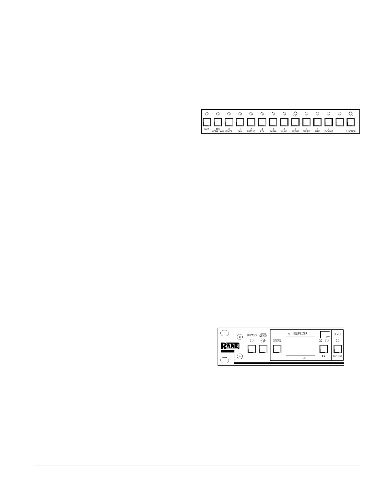
1. Make sure you’re in Normal Operating mode, and
then enter the curve weighting function by pressing CURVE WEIGHT . The CURVE WEIGHT
LED illuminates to verify that you’re in the curve
weighting function (as shown in the figure below). The SYSTEM display shows the default
Stored Memory which will be added to Working
Memory.
2. Enter the number of the Stored Memory that you
wish to add to Working Memory (if this is different from the default) using the number keys.
3. Press CURVE WEIGHT to activate the curve
weighting algorithm, or MEMORY to abort this
operation if you change your mind. The CURVE
WEIGHT LED turns off. You are returned to
Normal Operating mode. Working Memory now
contains the weighted curve.
Rane MPE Users Guide
11
Page 12

Placing The MPE In And Out Of
Lockout
Lockout disables the MPE front panel for those
who wish to make their equalizer tamper-proof. The
MPE provides two levels of lockout for maximum
flexibility. Lockout level 1 ( l.O.1) allows users to
recall Stored Memories, but that’s all. No alteration
of any MPE parameters is allowed. Lockout level 2
(l.O.2) disables the MPE front panel completely,
like it wasn’t even there.
To change the lockout status, you must enter a
password. If you don’t know the password, you’re
out of luck. The password is a three digit security
code, which is programmable by the user. Rane
ships the MPE with security code, “ 123”. You are
advised to change this since anyone with access to
this MPE Users Guide now knows that code. If you
forget your security code, you can use the universal
security code. We won’t print that here, since unfriendly eyes may be gazing at this page. If you are
the owner of an MPE, then you have received a
separate piece of paper explaining how to use the
universal security code.
To place the MPE in or out of lockout:
1. Make sure you’re in Normal Operating mode,
and then enter the Set Lockout function by
pressing F-LOCKOUT. The FUNCTION LED
illuminates and the LOCKOUT LED flashes,
indicating you are in the Set Lockout function
(see diagram below). The SYSTEM display
contains a flashing cursor, in preparation of
accepting the security code.
2. Enter the lockout security code (one digit at a
time, left to right) using the 0-9 keys. If the
security code is correct, you are advanced to step
3. If the security code is wrong, you are scolded
and returned to Normal Operating mode.
4. Press F-LOCKOUT to accept this new lockout
level and return to Normal Operating mode. If
you change your mind, and don’t want to place
the MPE in this new lockout level, press the
MEMORY key to escape. The FUNCTION and
LOCKOUT LED’s turn off.
To change the lockout security code:
1. Make sure you’re in Normal Operating mode,
and then enter the Set Lockout function by
pressing F-LOCKOUT. The FUNCTION LED
illuminates and the LOCKOUT LED flashes
indicating that you are in the Set Lockout function (as shown above). The SYSTEM display
contains a flashing cursor, in preparation of
accepting the current security code.
2. Enter the current lockout security code using the
number keys (0-9). If the security code is correct,
you are advanced to step 3. If the security code is
wrong, you are scolded and returned to Normal
Operating mode.
3. If you made it this far, the SYSTEM display
now shows the current lockout level. Press the 3
key to enter the “edit lockout security code” state.
The current security code now shows in the
SYSTEM display.
4. Type in the new security code using the 0-9 keys.
The digit currently under change flashes.
5. Press F-LOCKOUT to accept this new security
code and return to Normal Operating mode. If
you change your mind, and don’t want to replace
the old security code, press the MEMORY key
to escape to Normal Operating mode. The
FUNCTION and LOCKOUT LED’s turn off.
When the MPE is in lockout and someone presses
a key on the front panel that is not allowed, the
SYSTEM display flashes a momentary error message. Error messages are described in Appendix A.
3. If you made it this far, the SYSTEM display now
shows the current lockout level. A 00 means
lockout is currently inactive. A 11 means you’re
currently in lockout level 1. A 22 means you are
in lockout level 2. Enter the number corresponding to the lockout level desired ( 0,1, or 2).
12
Rane MPE Users Guide
Page 13

MIDI Operation
The MPE has very powerful MIDI capabilities. If
you are not exactly bursting with MIDI knowledge,
you might find it beneficial to take a break from the
MPE at this time and read a few of the MIDI references listed in Appendix C.
The MPE uses MIDI system exclusive messages
(SYSEX) to transmit information—lots of it. To
harness this power, without nuking your MIDI
system with loads of MIDI data, you should be
aware of which MPE SYSEX functions are necessary for your particular need. The big rule here is
this: do not configure the MPE to output SYSEX
data that is not needed . Repeat, do not configure
the MPE to output SYSEX data that is not
needed. If you break this rule, your MIDI sequencer
will get very mad at you and just clog up.
Before we go into SYSEX details, we need to
assign the MPE to a MIDI channel; decide whether
we want to operate in Omni mode; and whether we
want to transmit MIDI program change commands.
Let’s take a look at each in detail.
Setting The MIDI Channel
MIDI supports 16 separate channels of communication in one cable. This is accomplished by tagging
certain MIDI messages with a MIDI channel number, and requiring MIDI receivers to verify that this
channel number matches their own MIDI channel
assignment for valid reception. If a MIDI message’s
MIDI channel number does not match that of a
potential receiver, the receiver ignores it. Messages
generated and transmitted by the MPE are tagged
with the MIDI channel number you assign to the
MPE. Therefore, if you want two or more MPE’s to
talk to each other, or to other MIDI devices, they
must have the same MIDI channel assignment
(unless the receivers are in Omni mode, but more on
that later).
To assign a MIDI channel number to your MPE:
1. Make sure you’re in the Normal Operating mode,
and then enter the Set MIDI Channel function by
pressing the MIDI CHANNEL key. Do not get
this key confused with the CHANNEL 1 or
CHANNEL 2 keys on the MPE 14 . The MIDI
CHANNEL key is way over on the right side of
the front panel, next to the MEMORY key (see
the figure below). The MIDI CHANNEL LED
lights (and flashes if Omni mode is on, but that’s
getting ahead of ourselves…), and the current
MIDI channel number appears in the SYSTEM
display.
Rane MPE Users Guide
2. Enter the desired MIDI channel number using the
0-9, or UP and DOWN keys.
3. Press the MIDI CHANNEL key again to return
to the Normal Operating mode. The MIDI
CHANNEL LED turns off.
If you scroll past channel 16 (using the UP or
DOWN keys) you encounter an option called offoff.
Selecting offoff severs the MPE from the MIDI
system.
13
Page 14

Turning Omni Mode On And Off
Sometimes it is necessary to instruct the MPE to
listen to all MIDI channels, but to only transmit on
one particular channel. This is useful, for example, if
you want the MPE to listen to another MIDI device
but don’t know what channel the device is transmitting on. It is also useful when more than one MIDI
device is speaking to the MPE, and each is assigned
to a different MIDI channel.
Omni mode forces the MPE to accept messages on
all MIDI channels. The MIDI channel assigned to
the MPE is still attached to transmitted messages.
To place the MPE in Omni mode, or take it out of
Omni mode, perform the following steps:
1. Make sure you’re in the Normal Operating mode,
and then enter the Set Omni mode function by
pressing F-OMNI. The FUNCTION LED
illuminates, and the OMNI LED flashes telling
you you’re in the Set Omni Mode function (see
the diagram below). The SYSTEM display
shows the current status of Omni mode ( ON or
OFF).
2. Use the UP or DOWN key to toggle Omni mode
on or off.
3. Press F-OMNI to return to Normal Operating
mode when you’re finished. The FUNCTION
and OMNI LED’s turn off.
When Omni mode is on, and you are setting the
MIDI channel (as described in the previous section),
the MIDI CHANNEL LED flashes to remind you
the MIDI channel number only applies to transmitted messages.
Enabling MIDI Program Change Output
The MPE can be instructed to transmit MIDI
program change commands whenever a Stored
Memory is recalled via the MPE front panel. To do
so, perform the following steps:
1. Make sure you’re in Normal Operating mode, and
then enter the Set Program Change Output function by pressing F-PRGCHG . The FUNCTION
LED illuminates, and the PRGCHG LED flashes
indicating you are in this function (as shown
below). The current status of the MIDI Program
Change Output option appears in the SYSTEM
display (onon or offoff).
2. Use the UP or DOWN key to toggle MIDI
Program Change Output status on or off.
3. Press F-PRGCHG to return to Normal Operating
mode when you’re finished. The FUNCTION
and PRGCHG LED’s turn off.
Programming The MIDI Map
When the MPE receives a MIDI program change
command, it recalls a Stored Memory. The particular
Stored Memory that gets recalled is determined by
the MIDI map.
Without the MIDI map, a received MIDI program
change “X” would recall Stored Memory “ X”.
Program change 25 would recall Stored Memory
25. This is very rigid. For example, if you are
preparing an equalization curve for a particular
portion of a song, you have to ensure that the Stored
Memory number matches all the other devices in your
MIDI system. Otherwise, when your MIDI sequencer
sends the program change command for this passage,
the MPE would recall the wrong Stored Memory.
The MPE MIDI map redirects received MIDI
program change commands to any Stored Memory.
It can be thought of as a simple table, as shown
below. When MIDI program change “X” is received,
Stored Memory “ Y” is recalled.
Example Midi Map Table
Program Change # Recall Stored Memory #
1
2
3
4
5
6
:
:
10
10
3
68
128
1
:
:
14
Rane MPE Users Guide
Page 15
In the above table, a received program change 1
recalls Stored Memory 10. Program change 2 also
recalls Stored Memory 10. Program change 3
recalls Stored Memory 3, and so on. In general, any
program change command can recall any Stored
Memory. Multiple program change commands can
recall the same Stored Memory, but a single program change command can only recall one Stored
Memory.
To program the MIDI map:
1. Make sure you’re in Normal Operating mode, and
then enter the Program MIDI Map function by
pressing the MAP key. The MAP LED illumi-
nates, and the SYSTEM display shows a MIDI
program change number (see figure below).
2. Enter a different MIDI program change number
(if desired) using the number keys.
3. Press the MEMORY key. The MAP LED remains lit, the MEMORY LED flashes. The
SYSTEM display shows the Stored Memory that
the MIDI program change entered in step 2 will
recall. (See figure below.)
SYSEX
As mentioned earlier, there are two SYSEX
options that can be enabled for remote programming,
monitoring of MPE parameters, and sharing of data.
Wise use of these options is very important since
large amounts of MIDI data can be pumped into
your MIDI system if you’re not careful.
The three SYSEX options are Device ID, Key
Scan Echo, and Parameter Echo.
Setting The Device ID
Each MPE in a system is assigned a unique device
ID. This ID allows two MPE’s to communicate on
the same MIDI bus as millions of other MPE’s. Any
two or more MPE’s with the same device ID recognize each other. MPE’s with different device ID’s
ignore each other.
A special “ALL” (universal) device ID is also
available. Devices assigned to the universal ID will
talk to everybody. An MPE assigned to the universal
ID receives messages sent with any device ID. Any
MPE (regardless of it’s own device ID) receives
messages transmitted with the universal ID.
To assign a device ID to an MPE:
1. Make sure you’re in Normal Operating mode, and
then enter the Set Device ID function by pressing
F-DEVICE. The FUNCTION LED illuminates,
and the DEVICE LED flashes to verify that
you’re in the Set Device ID function (see the
figure below). The SYSTEM display shows the
current device ID.
4. Enter a different Stored Memory number, if
desired, using the number keys.
5. Repeat steps 1-4 until all desired map entries are
programmed.
6. Press MEMORY to return to Normal Operating
mode. The MAP LED turns off, the MEMORY
LED stops flashing.
Rane MPE Users Guide
2. Enter the desired device ID ( 1-127) using the
number or UP/DOWN keys. Entering number
128 (or scrolling to it) assigns the unit to device
ID allall(universal).
3. Press F-DEVICE to return to Normal Operating
mode when you’re finished. The FUNCTION
and DEVICE LED’s turn off.
Now that your MPE has an identity, it can talk to
the outside world, via MIDI SYSEX. Two types of
SYSEX messages can be enabled for transmission,
Key Scan Echo and Parameter Echo.
15
Page 16
Key Scan Messages
Key scan messages carry the status of the MPE
front panel. If the Key Scan Echo option is enabled,
any time you press or release a key on the MPE, it
sends a number corresponding to that key out the
MIDI OUT port. Any MPE of the same model, as
long as the MIDI channel and device ID match
properly, accepts these messages and processes them
as if those keys are pressed its own front panel. In
this way, one MPE can be configured as the master
controller over any number of slaves. When an MPE
is in lockout, received key scan messages are subject
to the same restrictions as keys pushed on its own
front panel.
To avoid the possibility that a key press is transmitted to another MPE, and the release of that key is
not (if you unplugged the MIDI cable before the key
was released, for example), MPE’s receiving key
scan messages assume the key presses are valid for
ten seconds only, before automatically releasing
them. If you are holding the UP or DOWN keys to
scroll through Stored Memories for more than ten
seconds, the receiving MPE(s) only recognize this
“phantom key press” for ten seconds before releasing.
Parameter Echo messages
Parameter Echo messages inform the outside
world of MPE parameter changes. If the Parameter
Echo option is enabled, any change to an equalizer,
expression or system parameter is transmitted to the
MIDI world and processed by other devices tuned to
the same MIDI channel and device ID.
Obviously, program change commands, Key Scan
Echo, and Parameter Echo can carry redundant
information. For example, if you recall a new Stored
Memory with all three of these options turned on,
the MPE sends a MIDI program change command,
the key presses to perform this operation, and the
parameters resulting from this program change
command. Any one of these messages, alone, could
suffice. Use these options with discretion.
If MIDI devices other than MPE’s are to change
programs, then you need to send them program
change commands. If you want remote MPE’s to
indicate the same key presses (i.e., you want a light
show), then you need to send them key scan messages. If you want to send the explicit parameters
then you need to send parameter messages.
To slave two or more MPE’s together, it is generally recommended you program one MPE (the
master) with all the desired parameters. Once this
master MPE is completely programmed, dump these
settings to the slaves (as explained later). Enable
MIDI Program Change Output on the master, and
turn off Key Scan Echo and Parameter Echo. When
you recall Stored Memories from the master, MIDI
program change commands instruct the slaves to
recall their internal Stored Memories (which you
pre-programmed with the desired contents above).
If you need to send new parameters to the slaves,
turn MIDI Program Change Output off, Parameter
Echo on, and then enter the changes on the master.
They will echo to the slaves. Try to adopt the habit
of disabling the MIDI output options you don’t need.
Further details on the MPE SYSEX implementation are covered in Rane documents:
MPE 14 MIDI System Exclusive Implementation
MPE 28 MIDI System Exclusive Implementation
You may obtain these documents by contacting
the factory.
Enabling Key Scan Echo and Parameter Echo is
straightforward. Details are covered below.
Enabling Key Scan Echo
1. Make sure you’re in Normal Operating mode,
then enter the Set Key Scan Echo function by
pressing F-KEY. The FUNCTION LED illuminates, and the KEY LED flashes to verify that
you are in this function (see the figure below).
The current Key Scan Echo status appears in the
SYSTEM display (onon or offoff).
2. Use the UP or DOWN key to toggle the status of
Key Scan Echo on or off.
3. Press F-KEY to return to Normal Operating
mode when you are finished. The FUNCTION
and KEY LEDs turn off.
16
Rane MPE Users Guide
Page 17

Enabling Parameter Echo
1. Make sure you’re in Normal Operating mode,
then enter the Set Parameter Echo function by
pressing F-PARAM . The FUNCTION LED
illuminates, and the PARAM LED flashes to
verify that you are in this function. The current
Parameter Echo status occupies the SYSTEM
display (onon or offoff).
2. Use the UP or DOWN key to toggle the status of
Parameter Echo on or off.
3. Press F-PARAM to return to Memory mode
when you are finished. The FUNCTION and
PARAM LED’s turn off.
Dumping The MPE Memory Via MIDI
SYSEX
The MPE dumps (transmits) the contents of its
Working Memory, Stored Memory, or MIDI map in
the form of a MIDI SYSEX message at your command. A device tuned to the same MIDI channel and
device ID will receive the dump. This is particularly
useful if you wish to save the contents of an MPE’s
memory, or to fill one MPE with the exact memory
contents of another.
To dump MPE memory:
1. Make sure you’re in the Normal Operating mode,
and then enter the Dump Memory function by
pressing F-DUMP. The FUNCTION LED
illuminates and the DUMP LED flashes, indicating you are in this function (see the figure below).
The SYSTEM display indicates the default
parameters the MPE will dump.
2. Use the UP or DOWN key to choose which of
the MPE parameters you wish to dump. They
will be displayed as cuRcuR (CURRENT Working
Memory), allall (all of Stored Memory), or
mapmap (MIDI map).
3. Once you have selected the parameters for regur-
gitation, press F-DUMP to execute the dump and
return to Normal Operating mode, or the
MEMORY key to abandon the dump and return
to Normal Operating mode. The FUNCTION
and DUMP LED’s turn off.
Since there is a lot of Stored Memory, the allall
dump takes approximately two seconds to complete.
The allall dump is executed in four pieces, each
one about 1200 bytes long. If your receiving device
can not handle a 1200 byte message, then you must
send Stored Memory manually. This is accomplished by recalling each Stored Memory, one at a
time, and storing it back to the same spot with
Parameter Echo on. Parameter Echo sends the new
Stored Memory via MIDI SYSEX. This may be
tedious, but it’s the receiving device’s fault. MPE’s
handle the entire data burst with no problem.
If you want to send all three sets of parameters
(Working Memory, Stored Memory, and MIDI map)
execute each dump individually.
An MPE receives a memory dump only if the
MIDI channel and device ID on each unit match, just
as with any other MIDI SYSEX message. The
dumper and dumpee must be the same model.
That about does it for operation of the MPE. If
you followed everything we’ve discussed so far, you
are well on your way to becoming a Zen master
ninja MPE operator.
Rane MPE Users Guide
17
Page 18
RPS 4 Remote Program Selector
In some applications, it may be desirable to switch
the MPE programs from a remote location, without
the use of a computer or MIDI controller. A simple
switch to change programs can also make operation
a lot easier for the non-technical person who may be
responsible for operating the sound system. The RPS
4 comes to the rescue.
Simply, the RPS 4 converts contact closures to
MIDI program changes. Depending on your requirements, the RPS 4 can generate up to 16 program
changes (1-16). These MIDI program change commands can simultaneously change your EQ curve(s)
on your MPE and/or any other MIDI controlled
device in your system. The sound equipment can
then be locked up in a rack somewhere else, possibly
minimizing cable runs and curious fingers. Presets
can be made for different program material, occupancy changes, different mics or placement, music
or speech. The switch can be located away from the
equipment rack. With the Rane FVL 22 Remote
Volume Level controller and the RPS 4, continuous
volume and EQ presets can be controlled by a
couple of knobs on a wall plate or in a lectern!
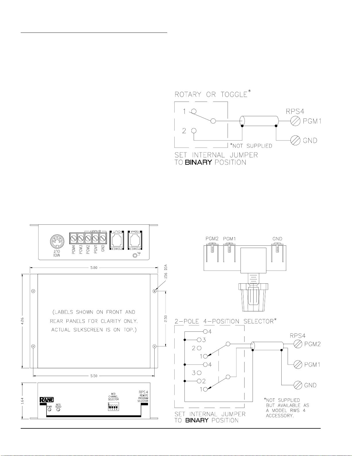
The wiring diagram for a simple two program
selector is shown below. This will toggle between
programs 1 and 2.
The Rane RWS 4 is a four position wall mount
switch designed to fit a 75 ohm coax wall plate. It
will supply four program changes to the MPEs using
any 3 conductor cable. Here's an actual size drawing
along with the wiring diagram.
18
Rane MPE Users Guide
Page 19
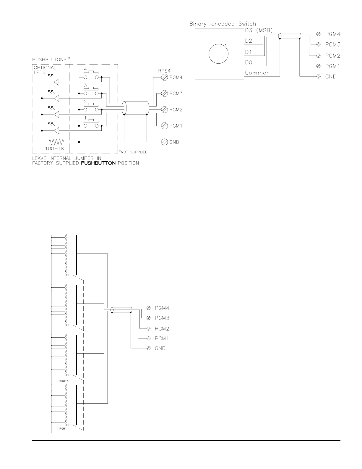
Here is a wiring diagram to use with momentary
contact pushbuttons with optional LED indicators.
This idea can be used for 2, 3 or 4 program changes.
Using a binary encoded switch, 16 MIDI program
changes can be activated. A four pole, sixteen throw
switch can also be used. A switch with fewer positions (such as an eight throw switch) may be used by
omitting the extra connections.
Use of the RPS 4 is pretty obvious and shouldn’t
present any problems. Here is a short check list:
1. Connect a MIDI cable (standard 5-pin DIN)
between the MIDI OUT jack on the RPS 4 and
the MIDI IN jack on the MPE. When controlling
more than one MIDI unit at a time, connect the
RPS 4 MIDI OUT jack to the MIDI IN jack on
the first MPE, then connect the MIDI THRU
jack from the first MPE to the MIDI IN jack on
the second MPE, and so on. (Do not use the MPE
MIDI OUT jacks. MPE MIDI OUTs won't carry
the program change.)
2. If controlling an MPE, disconnect the power
supply cable from the red POWER jack on the
MPE and reconnect it to the POWER jack on the
RPS 4. Next, using the cable supplied, connect
the POWER OUT jack on the RPS 4 to the
MPE’s red POWER jack. All other applications
require using the optional Rane RS 1 remote
power supply (NOT SUPPLIED). Connect the RS
1 to either red POWER jack.
Rane MPE Users Guide
3. Use the MIDI CHANNEL SELECTOR to set
the desired channel. All units being controlled
must use the same MIDI channel. Refer to the
diagrams on the top of the RPS 4 for the correct
switch settings.
4. The final step is wiring up the switches. Refer to
the diagrams above for several choices. The RPS
4 works with all types of switches.
Note there is an internal jumper option labelled
BINARY or PUSHBUTTON . All RPS 4s are
shipped with this jumper installed in the PUSH-
BUTTON mode. As the name implies, this is the
correct position when using momentary pushbuttons
to change programs. Changing the jumper to the
BINARY position allows using the minimum
number of interconnecting wires. Sometimes this
represents a significant cost savings and convenience.
19
Page 20
MPE Computer Software
There are some advantages to programming the
MPE's from a computer. Programs can be saved on
disk and backed up for security, and the MPE front
panel controls locked out if necessary. Because of
the compact rack height of the MPE, it is difficult to
provide a readable graphic display of the total
response curve as found on normal graphic equalizers. A computer allows you to see the actual response of the entire graph you are working on. This
is even more accurate than literal slider position on a
graphic equalizer because the actual response from
the interloping filters is correctly drawn. The smooth
response of interloping filters is apparant when
“tweaking” an adjacent band to nudge the center
frequency of a lobe where you want it.
The graphic screen allows control by either adjusting each slider just like a regular graphic EQ, or by
typing in specific values using the number pad on a
PC. The control screen allows changing of level,
memory #, device #, channel #, and ramp value,
along with all numeric filter values.
Your PC must have a midi interface installed to be
able to communicate with your MPE. If you have a
PC with card slots, an MPU-401 midi interface card
will need to be installed in your PC. After connecting MIDI cables (the MIDI out of the MPE goes to
the MIDI in of the MPU-401, and vice-versa), load
MPE28.EXE or MPE14.EXE depending on the
MPE you are using.
If you are using a laptop or don't have room for a
card, you can use a little box called a Midiator™
attached to your COM1 serial port. After connecting
MIDI cables both directions, load MPE28SER.EXE
or MPE14SER.EXE depending on your MPE. The
Midiator is available from Key Electronics TEL
(800) 533-MIDI).
When the program boots, it checks to see if you
have an operating MIDI interface installed. It then
attempts to turn Omni Mode off, Key Echo on,
Parameter Echo on, and Program Change on. If all is
well, the following key commands are activated:
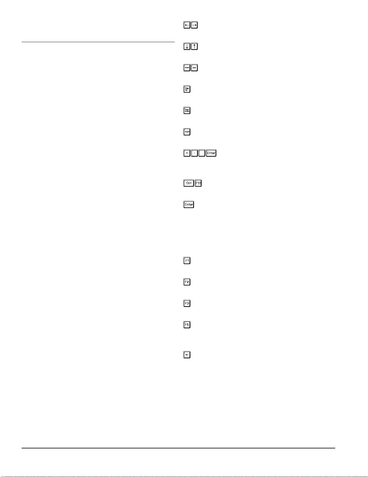
Left & Right Arrow Keys:
Move the cursor across the screen.
Up & Down Arrow Keys:
Change the current active parameter.
Home & End Keys:
Skip towards beginning and end of bands.
Page-Up Key:
Set active parameter to its maximum level.
Page-Down Key:
Set active parameter to its minimum level.
Insert Key:
Set active parameter to 0 (dB).
+/- (number) <Enter>:
Direct Entry (most parameters):
press + or -, 1 to 3 digits, and <Enter>.
<Control + F10>:
Flatten EQ curve for one channel.
<Enter> (cursor on memory no.):
Storing the working memory:
With the cursor on MEMORY, press <Enter>.
Press <Enter> again to store to the current
memory. Or change the current memory number
and press <Enter> again to store the patch.
F1:
Switch between Control and Graph screens.
F2:
Save all MPE Stored Memories to Disk.
F3:
Recall all MPE Stored Memories from Disk.
F5:
Stop MPE front panel display of computer cursor
position until program is restarted.
Escape:
Out to this screen & to exit the program.
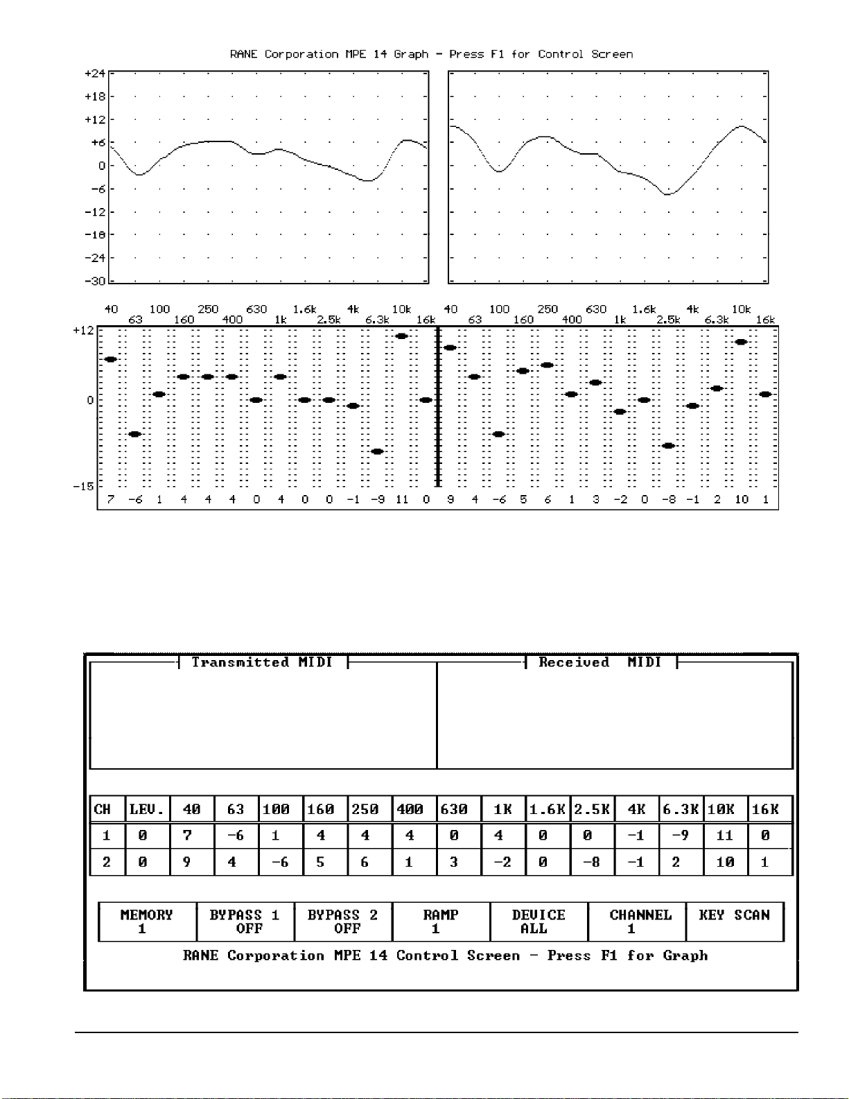
The MPE 14 graph screen is shown at the top of
the following page, and the control screen is shown
at the bottom. This DOS program is supplied at no
charge from the Rane factory (by request). For
Macintosh™ users, Opcode Systems has a Galaxy
librarian for the MPE series.
20
Rane MPE Users Guide
Page 21
Rane MPE Users Guide
21
Page 22
Applications
Now for the fun part, using the MPE. The MPE
hooks up to other audio equipment just like a standard graphic equalizer. Audio goes in the audio
input and comes back out the audio output. Don’t
forget to connect power to the MPE.
There are an endless variety of MIDI setups that
could accommodate the MPE. A few simple ones
appear below. In all cases, the MIDI OUT of one
device connects to the MIDI IN of another device.
MIDI THRU’s are used for daisy-chaining, but
should not be used to connect more than four devices together. If you need to connect more than four
devices, use a MIDI Thru box (splitter).
If you want to bring the MIDI OUT’s of more
than one MPE to a single device, then you need a
MIDI Merger. MIDI Mergers take two or more
MIDI cables and combine them to one. Never try to
use a Y-connector to combine two or more MIDI
cables. It won’t work.
With these basic ground rules in mind, here are
some typical setups.
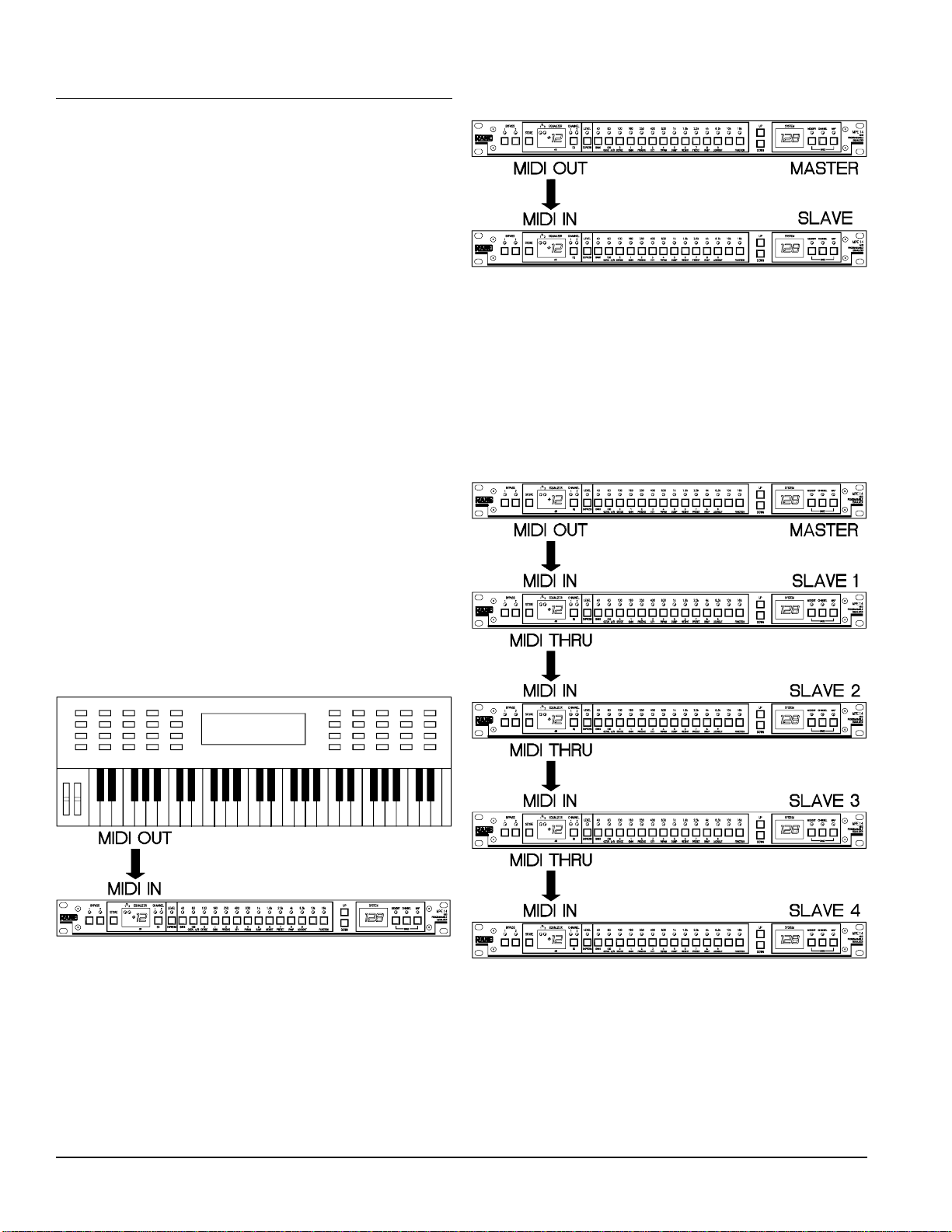
Example 1:
One MPE connected as a slave to a MIDI keyboard. Note that any MIDI device could be substituted for the keyboard.
Example 2:
Two MPE’s in master-slave configuration.
Notice that the MIDI OUT of the master is
connected to the MIDI IN of the slave. With Key
Scan Echo and/or Parameter Echo enabled on the
master, key presses and/or parameter changes are
transmitted to the slave.
Example 3:
Master-slave configuration with 4 slaves, using
MIDI THRU’s.
The keyboard sends MIDI program change commands to the MPE. It also sends MIDI channel
pressure aftertouch or continuous controller data for
the Expression feature.
22
As in example 2, with the proper SYSEX echo
option enabled, the master controls the slaves.
Each slave is given a different device ID. The
master communicates with each slave independently
by adjusting its device ID to match each slave.
Only use MIDI THRU’s with 4 or less slaves.
Rane MPE Users Guide
Page 23
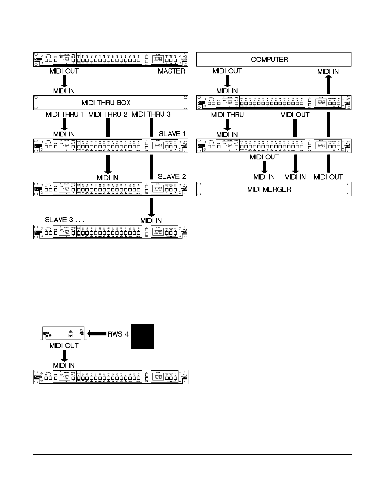
Example 4:
Master-slave configuration with 3 slaves, using a
MIDI Thru box.
Example 6:
Computer-controlled system with MIDI Merger.
This setup is similar to example 3, with the addition of a MIDI Thru box to increase the number of
possible slaves. Although only three slaves are
shown, any number may be used (limited by the
number of outputs on the MIDI Thru box).
Example 5:
Remote wall switch control of program changes.
The computer sends data to both MPE’s. The
MIDI OUT of each MPE is merged and returned to
the computer’s MIDI IN. In this system, the computer can establish two-way communication with
both MPE’s. With a Merger capable of more than
two MIDI IN’s, more MPE’s could be supported.
The computer could also be a MIDI sequencer or
other MIDI system controller.
The RWS 4 is a simple 4 position switch that
sends contact closures to the RPS 4. Contact closures are converted to MIDI program change commands. This configuration allows MIDI programs 14 to be remotely activated, while the MPE remains
in Lockout Mode. See page 18 for RPS 4 details.
Rane MPE Users Guide
23
Page 24

Battery Maintenance
The MPE contains a battery to keep the memory
alive during power down. The battery should last
five years, as long as you abide by the following
tips:
Problem:
The MPE is powered up, but no lights come on
and it doesn’t respond to key presses.
Troubleshooting:
1. Is the MPE really powered up? Verify that both
ends of the remote supply are plugged in.
Keep your MPE in a cool place. Battery life
takes a dive when it gets hot.
Keep your MPE powered from the power supply
as much as possible. As long as the MPE has
power, it doesn’t use the battery.
The battery should be checked every year or so.
This can be carried out at any Rane warranty station.
If the battery needs replacement, do not attempt to
do it yourself. Take it to the nearest Rane warranty
station, or call the factory for instructions. Failure to
do so may result in loss of all Stored Memory.
Troubleshooting
The MPE really does work, we promise. But that’s
what they all say, right? In this section we provide
some guidelines to aid you in troubleshooting your
system in the case that it does not perform the way
you expect it to.
Obviously, the assumption here is that all your
equipment works. The MPE will not talk to MIDI
equipment that isn’t turned on, doesn’t do what it’s
supposed to, or isn’t connected properly. If your
system doesn’t work, the first thing you should do is
check all your cables and verify that the proper
connections have been made. In 90% of the cases,
this will eradicate your problems. If you’ve checked
your cables, and the system still doesn’t work, read
on.
2. Does the MPE pass audio? (Try bypass.)
Y—The MPE has power if it passes audio. Discon-
nect MIDI (in case garbage is pouring in and
preventing the MPE from servicing its user
interface) and power it up again.
N—If no audio passes, the MPE does not have
power. Check your connections.
Problem:
The MPE does not pass audio.
Troubleshooting:
1. Is the MPE plugged in? Verify that LEDs are lit,
and that the unit is operating.
2. Are the audio cables connected to the proper
inputs and outputs?
3. Try Bypass. If the MPE does not pass audio in
Bypass, it either has no power or the cables are
improperly connected.
4. Are all the Bands and overall Level set for large
cut? It is conceivable that you could have up to
40 dB of attenuation through the unit if all Bands
and overall Level are set for maximum cut.
Problem:
The MPE does not respond to the keypad.
Troubleshooting:
1. Is the MPE locked out? Check for an error message (L.O.1 or L.O.2) when you press a key. If
you get the error message, then you are locked
out. See the detailed operating instructions to
learn how to remove the MPE from Lockout.
24
2. Is the MPE receiving Key Scan messages? If so,
it could possibly be timing out a MIDI key press
that wasn’t accompanied by a MIDI key release.
The MPE will time out and return control to the
front panel after ten seconds if no MIDI key
release command is received. To test this for
condition, disconnect the MIDI IN cable, wait for
ten seconds, and then try the keypad again.
Rane MPE Users Guide
Page 25

Problem:
The MPE doesn’t receive MIDI program change
commands.
Troubleshooting:
Problem:
The MPE doesn’t communicate with another MPE
via MIDI SYSEX.
Troubleshooting:
1. Is the MIDI cable plugged in correctly? The
MIDI Out of the transmitting device should be
connected to the MIDI IN of the MPE. MIDI
cables should not exceed 50 feet in length. If your
cable is longer than this, try a shorter one.
2. Is the transmitting device properly configured to
transmit MIDI program change commands?
Verify that the MPE is receiving these messages.
3. Is the MPE set to the correct MIDI channel?
Both the transmitting device and the MPE must
be set for the same MIDI channel, or the receiving MPE should be in Omni mode (see the
detailed operating instructions for details on how
to enable Omni mode).
4. Is the MIDI map redirecting the received program
change command to a different internal Stored
Memory?
Problem:
The MPE doesn’t send MIDI program change
commands.
Troubleshooting:
1. Verify that both units are set to the same device
ID (or at least one of them to the ALL ID) and
that they are on the same MIDI channel (or the
receiving MPE is in Omni mode).
2. Are your MIDI cables hooked up? Check that the
MIDI Out of the transmitter connects to the MIDI
In of the receiver. Make sure your cables are not
over 50 feet in length.
3. Are the desired SYSEX options enabled? To
transmit key scan messages you must enable the
Key Scan Echo option. To transmit parameter
message you must enable the Parameter Echo
option. See the detailed operating instructions for
details.
1. Is the MIDI cable connected properly? The MIDI
OUT of the MPE should be hooked to the MIDI
IN of the receiving device. MIDI cables should
not exceed 50 feet in length. If your cable is
longer than this, try a shorter one.
2. Is the Program Change Output option enabled?
The MPE must be told to output MIDI program
change commands. Consult the detailed operating
instructions for details.
3. Is the MPE set to the correct MIDI channel?
Both the MPE and the receiving device must be
set for the same MIDI channel, or the receiver
should be in Omni mode.
4. Is the receiving device properly configured to
receive MIDI program change commands? Some
devices allow you to disable MIDI program
change reception, verify that your device is
properly enabled.
Rane MPE Users Guide
25
Page 26

Appendix A: Error Codes
Appendix B: Ramp Details
The MPE scolds you with error codes (on the
SYSTEM display) whenever you enter a key press
that is invalid. These error codes are defined below.
Er.1Er.1 – Entry to mode or function not allowed.
This message appears when you try to enter a
mode or function from the wrong mode. For
example, if you try to access the EQ Edit mode
clear function from the Normal Operating mode,
you are scolded with this message.
Er.2Er.2 – Number out of range.
You are trying to enter a number that is too large
or small for a particular parameter.
Er.3Er.3 – Key undefined in this mode or function.
You are pressing a key that is invalid (i.e. unused) for a particular mode or function.
Er.9Er.9 – Invalid lockout security code.
You typed in the wrong security code.
L.O.1L.O.1 – Device is locked out at level 1.
You may recall a Stored Memory, but you cannot
change it.
L.O.2L.O.2 – Device is locked out at level 2.
All keypad entries are disallowed, except the
proper unlock procedure.
(For advanced users only, not necessary for
normal operation)
Any instantaneous change to the level of a bandlimited audio signal is accompanied by a small
overshoot. Aurally, this reveals itself as a “pop”.
This is a fact of life, as dependable as taxes and
death.
When an equalizer creates a rapid level change a
small pop is emitted. The bigger or more rapid the
change, the bigger the bang. This is not a problem
with manually adjusted analog equalizers since it is
unlikely that anybody could move a slider fast
enough to cause an instantaneous change of level.
However, a programmable equalizer changes curves
in a matter of microseconds—plenty quick enough
to generate an onslaught of thundering snaps, crackles and pops.
The MPE’s provide a special control to combat
this nemesis, the EQ Ramp. The EQ Ramp constrains curves to change in small increments, programmable in decibel step sizes. This causes the
instantaneous curve changes to be small, reducing
the magnitude of any overshoots to inaudibility.
Although the EQ Ramp is adjusted in terms of
decibel step size, you may wish to determine how
much time a curve transition requires. This is not
entirely straightforward. The ramp operates in the
“decibel step size domain”, rather than the “time
domain”. This appendix delineates the process of
translating from the decibel domain to the time
domain.
The software internal to the MPE is “multitasking”. Concurrent tasks include; scanning the keypad
and processing user input, refreshing the LED
displays, watching for MIDI, and changing EQ
curves. The MPE’s CPU is time shared among these
tasks. Changes to EQ curves are scheduled in this
multitasking environment. Consequently, while a
curve changes it must share the MPE’s CPU with
other active tasks. The result is a variation in the
time a curve transition requires. What all this means
is the calculations that ensue have a small error
tolerance of several milliseconds.
26
Rane MPE Users Guide
Page 27
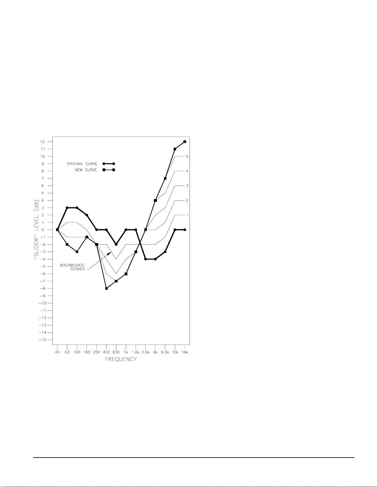
Computing EQ Ramp Transition Time
In the figure below an MPE 14 is in transition
between two curves (the heavy lines). The Ramp is
set for 2 dB steps, resulting in intermediate curves 1-
5. To compute the total time required for the EQ
change you must add up the time required for each
step. The number of steps is determined from the
band (or overall level) that makes the largest change,
divided by the Ramp step size. In this example, the
16 kHz band makes the largest change of 12 dB. The
Ramp is set for 2 dB increments, requiring 12/2 = 6
steps to execute the EQ change.
Now we will calculate Tstep for each of the 6
Ramp steps (assume overall levels are 0dB for both
curves, and both channels are identical):
Tstep 1 = (26 x 200µs) + (0 x 900µs) + (4 x 70µs) + 600µs
= 5.94ms
Tstep 2 = (24 x 200µs) + (0 x 900µs) + (6 x 70µs) + 600µs
= 5.82ms
Tstep 3 = (18 x 200µs) + (0 x 900µs) + (12 x 70µs) + 600µs
= 5.04ms
Tstep 4 = (8 x 200µs) + (0 x 900µs) + (22 x 70µs) + 600µs
= 3.74ms
Tstep 5 = (6 x 200µs) + (0 x 900µs) + (24 x 70µs) + 600µs
= 3.48ms
Tstep 6 = (4 x 200µs) + (0 x 900µs) + (26 x 70µs) + 600µs
= 3.22ms
Total time = 5.94 + 5.82 + 5.04 + 3.74 +3.48 +3.22
= 27.24ms
Step 1: 26 bands (13 per channel) changed. No
overall levels changed. The 26 bands that
changed required 26 x 200µs. The stationary
bands and overall levels required 4 (2 bands + 2
overall levels) x 70µs. The software overhead
was 600µs. The grand total was 5.94ms.
The time required for each step is calculated as
follows:
Tstep = (number of bands that change) x Tbc
+(number of overall levels that change) x Tlc
+ (number of bands and levels that don’t change) x Tnc
+ Toh
where:
Tnc = Time for EQ band or overall level to not change = 70µs
Tbc = Time for EQ band to change one step = 200µs
Tlc = Time for overall level to change one step = 900µs
Toh = Time required for overhead per step = 600µs
Step 2: 24 bands changed, 4 didn’t. Two overall
levels didn’t change. This required (24 x 200µs)
+ (6 x 70µs) + 600µs = 5.82ms.
Steps 3-6 were derived similarly.
The time required for the EQ change in the above
figure is at least 27.24ms (the actual time is probably
1ms-5ms higher due to competing software tasks).
If the Ramp step size is changed to 1dB, a total of
12 steps is required. Since each intermediate step is
unique, simply doubling the time derived with 2dB
steps will not yield the correct answer. The additional 6 steps must be computed and added to the
above total.
So, unless you really really really really need to
determine the exact time a curve transition takes,
don’t bother. The quickest transition occurs when
one band changes in one ramp step. This takes
2.83ms. The longest transition occurs when all bands
change 27dB, and overall level changes 24dB, with
the Ramp set for 1dB steps (overall levels will be
constrained to 2dB steps since this is the smallest
overall level increment). This requires 191.7ms.
Therefore, all EQ changes will take anywhere from
about 3ms to 200ms to execute. The actual time will
be a little higher (typically 5%) due to competing
software tasks.
Rane MPE Users Guide
27
Page 28

Real World Example
Let’s put this into MIDI studio language. Suppose
we use the ramp as an effect to cross fade into a new
section of a song. We want the fade to end on a
given beat. For this example the tempo is 120bpm
(beats per minute). Therefore one beat of 4/4 will be
1/2 second (500ms). The sequencer resolves into
bar:beat:ticks with 120 ticks per beat (4.2ms between ticks).
We determined that EQ changes take 3ms to
200ms, depending on the details given above. At
4.2ms per tick this translates to approximately 1 to
50 ticks. Therefore the crossfade (program change to
the MPE) should begin 1 to 50 sequencer ticks
before the “hit”.
Appendix C: References
The following references provide further information on interpolating constant-Q equalizers and
MIDI.
1. D. Bohn, “Constant-Q Graphic Equalizers,” J.
Audio Eng. Soc. , vol. 34, pp. 611-626 (Sept. 1986).
2. Terry Pennington, The Rane GE 30 Interpolat-
ing Constant-Q Equalizer, Rane Note 117 (Rane
Corp., 1987).
3. MIDI 1.0 Detailed Specification (International
MIDI Association, Los Angeles, 1988).
4. Craig Anderton, MIDI For Musicians (Amsco
Publications, New York, 1986).
5. Jeff Rona, MIDI, the Ins, Outs & Thrus (Hal
Leonard Books, Milwaukee, 1987).
6. Bob Moog, “MIDI: Musical Instrument Digital
Interface,” J. Audio Eng. Soc ., vol. 34, pp. 394-404
(May 1986).
7. Bob Moses, Steve Turnidge, Much Ado About
MIDI, Rane Note 120 (Rane Corp.,1989).
8. Ray Miller, Bob Moses, MPE’s Adopted By
Wolves, Rane Note 125 (Rane Corp.,1990).
28
Rane MPE Users Guide
Page 29

Appendix D: MPE 14 Factory Presets
Preset Ch Level 40 63 100 160 250 400 630 1k 1.6k 2.5k 4k 6.3k 10k 16k
1
Comment: Stereo Flat
2
Comment: Stereo All 6dB Boost
3
Comment: Stereo All Full Cut
4
Comment: Stereo Low Cut
5
Comment: Stereo High Cut
6
Comment: Stereo Low End Punch
7
Comment: Stereo High End Rolloff
8
Comment: Stereo Hum Cut
9
Comment: Stereo Low Shelving Boost (3dB)
10
Comment: Stereo Low Shelving Boost (6dB)
11
Comm ent: S tereo Low She lving C ut (3dB)
12
Comm ent: S tereo Low She lving C ut (6dB)
13
Comment: Stereo High Shelving Boost (3dB)
14
Comment: Stereo High Shelving Boost (6dB)
1000000000000000
2000000000000000
1-1266666666666666
2-1266666666666666
1 0 -15 -15 -15 -15 -15 -15 -15 -15 -15 -15 -15 -15 -15 -15
2 0 -15 -15 -15 -15 -15 -15 -15 -15 -15 -15 -15 -15 -15 -15
10-158110000000000
20-158110000000000
100000000000118-15
200000000000118-15
1062-100000000000
2062-100000000000
10000000000-1-1-2-3-5
20000000000-1-1-2-3-5
108-1510-158110000000
208-1510-158110000000
1022110000000000
2022110000000000
1053211000000000
2053211000000000
10-2-2-1-10000000000
20-2-2-1-10000000000
10-5-3-2-1-1000000000
20-5-3-2-1-1000000000
1000000000000113
2000000000000113
1000000000000126
2000000000000126
Rane MPE Users Guide
29
Page 30

Preset Ch Level 40 63 100 160 250 400 630 1k 1.6k 2.5k 4k 6.3k 10k 16k
15
Comment: Stereo High Cut Shelving (3dB)
16
Comment: Stereo High Cut Shelving (6dB)
17
Comment: Synthesized Stereo 1
18
Comment: Synthesized Stereo 2
19
Comment: Resonant 1
20
Comment: Resonant 2
21
Comment: Stereo Camel Back Curve
22
Comment: “Rhythm electric guitar. Use bass pickup. Drops midrange to make room for vocals.”*
23
Comment: “Jazz guitar lead. Use with bass or treble pickup.”*
24
Comment: “Mr. Blues—try both pre and post fuzz, treble or bass pickup.”*
25
Comment: “Stereo Spreader—feed mono signal into both inputs—generates stereo image.”*
26
Comment: “MIDI panner—feed mono signal into both inputs—use MIDI controller to pan.”*
27
Comment: “HR-16 drum machine enhancer.”*
* Presets courtesy of Craig Anderton.
1000000000000-1-1-3
2000000000000-1-1-3
1000000000000-1-2-6
2000000000000-1-2-6
100000006-12405-1260
2000006-12505-126000
1000000-12505-126000
200000006-12405-1260
1000141-1511-15141000
20000141-1511-1514100
10000141-1511-1514100
2000141-1511-15141000
1-2234560-3-3-303466
2-2234560-3-3-303466
100001-3-5-5-7-604340
200001-3-5-5-7-604340
1000322222365-6-15-15
2000322222365-6-15-15
100000002620060-12
200000002620060-12
10-88-88-88-88-88-88-88
208-88-88-88-88-88-88-8
1 0 -12! 12¡ -12! 12¡ -12! 12¡ -12! 12¡ -12! 12¡ -12! 12¡ -12! 12¡
2 0 12¡ -12! 12¡ -12! 12¡ -12! 12¡ -12! 12¡ -12! 12¡ -12! 12¡ -12!
1002200-1-11030023
2002200-1-11030023
30
Rane MPE Users Guide
Page 31

Appendix E: MPE 28 Factory Presets
Preset Level 31.5 40 50 63 80 100 125 160 200 250 315 400 500 630 800 1k 1.25 1.6k 2k 2.5k 3.15 4k 5k 6.3k 8k 10k 12.5 16k
1 0 0000000000000000000000000000
Comment: Flat
2 -126666666666666666666666666666
Comment: Boost with Low Gain
3 0 -15 -15 -15 -15 -15 -15 -15 -15 -15 -15 -15 -15 -15 -15 -15 -15 -15 -15 -15 -15 -15 -15 -15 -15 -15 -15 -15 -15
Comment: Full Cut
4 0-11-4-52110000000000000000000000
Comment: Low Cut
5 0 000000000000000000000001140-13
Comment: High Cut
6 0 2542000000000000000000000000
Comment: Low End Punch
7 0 0000000000000000000-1-1-1-2-2-2-3-3-7
Comment: H igh End Rol loff
8 0 101-1056-12410000000000000000000
Comment: Hum Cut
9 0 1222111110000000000000000000
Comment: Low Shelving Boost (3dB)
10 0 3443222111100000000000000000
Comment: Low Shelving Boost (6dB)
11 0 -1-2-2-2-1-1-1-1-10000000000000000000
Comment: Low Shelving Cut (3dB)
12 0 -2-4-4-3-2-2-2-1-1-1-100000000000000000
Comment: Low Shelving Cut (6dB)
13 0 0000000000000000000000111123
Comment: H igh Shelving Boost (3dB)
14 0 0000000000000000000000112335
Comment: H igh Shelving Boost (6dB)
15 0 0000000000000000000000-1-1-1-1-2-3
Comment: H igh Shelving Cut (3dB)
16 0 0000000000000000000000-1-1-2-3-3-5
Comment: H igh Shelving Cut (6dB)
17 -2 223334464641-1-2-3-2-3-30-123454665
Comment: Camel Back Curve
18 0 000000000-2-4-4-5-5-6-6-6-6-3-223333412
Comment: Rhythm Guit ar —drops midr ange to make room f or vocals*
19 0 0000222222222222334442-1-7-9-15-14-14
Comment: Jazz Guitar Lead*
20 0 0000000000001344430101242-3-2-12
Comment: Blues Guitar*
21 0 00122211000-1-1-101011311100232
Comment: Drum Machine Enhancer*
*Presets courtesy of Craig Anderton
Rane MPE Users Guide
31
Page 32

Index
A
Adding two curves ................................................ 10
Aftertouch ............................................................. 22
editing ................................................................. 9
Applications .......................................................... 22
Assigning MIDI Channel ...................................... 13
Auto-Detect ............................................................ 9
B
D
Definitions
Auto-Detect ......................................................... 9
equalizer parameters ............................................ 2
expression ........................................................... 2
expression controller ........................................... 9
expression vector ................................................. 9
stored memory .................................................... 2
Working Memory ................................................ 2
Description of models ............................................. 1
Device ID ............................................................. 15
DO S...................................................................... 20
Dump .................................................................... 17
Bank ....................................................................... 5
Base ........................................................................ 5
Battery .................................................................. 24
Boost
level, MPE 14 ...................................................... 6
level, MPE 28 ...................................................... 7
with expression ................................................... 9
Buttons (Keys) ........................................................ 2
Bypass .................................................................... 4
C
Channel pressure aftertouch .................................... 9
Chicken .................................................................. 6
Clear function ......................................................... 7
Combining curves ................................................. 10
Compare function ................................................... 7
Computer .............................................................. 20
Continuous controllers ............................................ 9
Conventions and terminology .................................. 2
Copying one stored Memory to another ................... 7
Curve
crossfades using the ramp .................................... 8
definition of ......................................................... 2
drawing ............................................................. 20
savin g .................................................................. 7
Curve Weighting ................................................... 10
Cut
level, MPE 14 ...................................................... 6
level, MPE 28 ...................................................... 7
with Expression ................................................... 9
E
EQ Edit mode
decription of ........................................................ 3
entering ............................................................... 3
Equalizer parameters ............................................... 2
Error Codes ........................................................... 26
Expression
auto detect, MPE 14 ............................................ 9
auto-detect, MPE 28 .......................................... 10
controller ............................................................. 9
definition of ......................................................... 2
editing ................................................................. 9
parameters ........................................................... 2
vector .................................................................. 9
Expression Edit mode
description of ...................................................... 3
entering ............................................................... 3
recognizing .......................................................... 4
F
Factory Presets
definition of ......................................................... 2
recalling .............................................................. 8
Flatten (Clear) ......................................................... 7
Front panel conventions .......................................... 2
FUNCTION Key ..................................................... 2
Functions
enable Omni mode ............................................ 14
enable program change output ........................... 14
set device ID ..................................................... 15
set Ramp ............................................................. 8
32
Rane MPE Users Guide
Page 33

K
M
Key scan ............................................................... 16
Keys
BANK ................................................................. 5
BYPASS ............................................................. 4
CURVE WEIGHT ............................................. 10
definition of ......................................................... 2
DEVICE ............................................................ 15
DUMP ............................................................... 17
EQ....................................................................... 3
EXPRESS ........................................................... 9
KE Y .................................................................. 16
LOCKOUT ........................................................ 12
MAP ............................................................ 5, 14
MEMORY ..................................................... 3, 7
MIDI CHANNEL .............................................. 13
multiple labels ..................................................... 2
OCTAL A/B ........................................................ 5
OMNI................................................................ 14
PARAM ............................................................ 17
PRESET .............................................................. 8
PRGCHG .......................................................... 14
RAMP ................................................................. 8
STORE ................................................................ 7
WEIGHT ........................................................... 10
L
L.O.1...............................................26
L.O.2 .............................................. 26
Lockout ................................................................ 12
Master ................................................................... 22
MEMORY LED flashing ........................................ 7
MIDI
channel .............................................................. 13
channel pressure aftertouch ................................. 9
computer control ............................................... 23
continuous controllers ......................................... 9
device ID .................................................... 15, 23
Key Scan ........................................................... 16
Map
dumping to another MPE ............................... 17
programming ................................................. 14
master-slave ...................................................... 22
merger ............................................................... 22
Omni mode ....................................................... 14
operation ........................................................... 13
parameter echo .................................................. 16
usage.............................................................. 17
program change .......................................... 14, 25
setting MIDI channel ......................................... 13
SYSEX
memory dump ................................................ 17
usage.............................................................. 15
thru.................................................................... 22
turning off MIDI ............................................... 13
Modes ..................................................................... 3
MPE 14
copy channel ....................................................... 6
editing EQ parameters ......................................... 6
editing expression ................................................ 9
level (gain), changing .......................................... 6
MPE 28
editing EQ parameters ......................................... 6
editing expression ................................................ 9
level (gain), changing .......................................... 7
Rane MPE Users Guide
N
Normal Operating Mode ......................................... 3
Number Keys .......................................................... 2
O
Octal A/B ................................................................ 5
Omni Mode ........................................................... 14
33
Page 34

P
V
Parameter echo ..................................................... 16
Patch ....................................................................... 2
Pops ........................................................................ 8
Preset
MPE 14 ............................................................. 29
MPE 28 ............................................................. 31
recalling factory .................................................. 8
stored memory .................................................... 2
PRGCHG .............................................................. 14
Problems ............................................................... 24
Program .................................................................. 2
Program Change ................................................... 14
R
Ramp
calculating transition time ................................. 27
definition of ......................................................... 8
timing ................................................................ 26
References ............................................................ 28
Remote program switching ................................... 18
RPS 4 .................................................................... 18
Vector ..................................................................... 9
W
Weighting ............................................................. 10
Working Memory
definition of ......................................................... 2
dumping to another MPE ................................... 17
storing ................................................................. 7
Z
Zen ....................................................................... 17
S
Security code ........................................................ 12
Slave ..................................................................... 22
Snake ...................................................................... 6
Software ............................................................... 20
Stored Memory
comparing ........................................................... 7
definition of ......................................................... 2
dumping to another MPE ................................... 17
recalling curves from ........................................... 4
recalling with UP and DOWN ............................. 5
storing ................................................................. 7
Sudsy beverage ....................................................... 4
Summing curves ................................................... 10
System parameters .................................................. 2
T
Terminology ........................................................... 2
Transmit memory .................................................. 17
Troubleshooting .................................................... 24
U
Up and Down Keys ................................................. 5
User Features summarized ...................................... 3
User modes description ........................................... 3
34
Rane MPE Users Guide
 Loading...