

Page 1
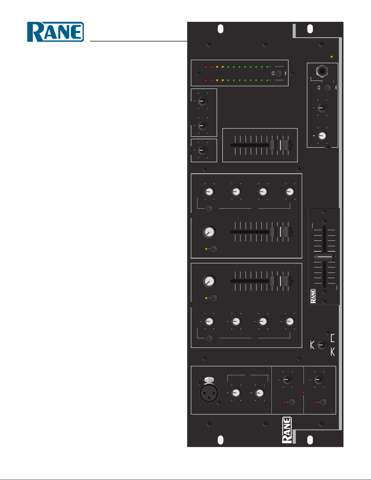
MP 22z
CUE LEFT
CUE PGM
PGM RIGHT
M
ONO
+8
+5+1+3
PEAK dBu
-3-1-7
-5
-10
-15
-20
LEFT RIGHT
0
C
UE/PGM
6
4
1
0
8
0
8
2
ZONE 2
6
4
6
1
0
2
0
Z
ONE 1
8
1
0
10
8
0
dB
2
4
4
2
0
4
2
4
C
UT
E
Q ENGAGE
2
B
OOST
10
8
4
624
2
4
4
C
UT
1
0
0dB
2
4
C
UT
624
B
OOST
BOOST
2
2
L
EVEL
STEREO
8
6
4
1
0
2
0
0
2
P
GM
6
2
C
UE
6
L
EVELPAN
0
2
4
2
4
C
UT
0
B
OOST
L
INE 5L
INE 4
PH/LN2
LINE 3 LINE 4
LINE 5
1
0
8
624
1
0
0dB
624
4
C
UT BOOST
2
2
4
E
Q ENGAGE
4
C
UT BOOST
2
4
2
C
UT BOOST
4
4
2
2
624
8
1
0
PH/LN1
TM
0
1
06 8
0
420
04
26810
2
4
2
C
UT BOOST
4
0
4
2
2
B
OOST
4
B
OOST
4
4
CUT
C
UT
2
2
8
M
AX
2
MIN
O
L
6
M
AX
8
4
M
IN
2
E
NGAGE
ENGAGE
4
6
L
INE 6
ACTIVE CROSSFADER
PWR
MIXER
AUX OUTPUT LEVELS
B
HI-MID
TREBLE
MID
BASS
EQ B
MASTER LEVEL
HEADPHONE CONTROL
B
CUE B
INPUT SELECT
A
TREBLE
CUE A
HI-MID
MID
BASS
EQ A
CROSSFADER
CONTOUR
A
MAIN MIC
TREBLE
BASS
MIC EQ
REMOTE MIC
MAIN MIC
INPUT SELECT
MP 22z
F
60
CLUB MIXER
Page 2
RISK OF ELECTRIC SHOCK
DO NOT OPEN
CAUTION
IMPORTANT SAFETY INSTRUCTIONS
1. Read these instructions.
2. Keep these instructions.
3. Heed all warnings.
4. Follow all instructions.
5. Do not use this apparatus near water.
6. Clean only with a dry cloth.
7. Do not block any ventilation openings. Install in accordance with manufacturer’s instructions. If rackmounting, provide adequate
ventilation. Equipment may be located above or below this unit, but some equipment (like large power amplifiers) may cause an
unacceptable amount of hum or may generate too much heat and degrade the performance of this equipment.
8. Do not install near any heat sources such as radiators, heat registers, stoves, or other apparatus (including ampliers) that produce
heat.
9. Do not defeat the safety purpose of the grounding-type plug. A grounding-type plug has two blades and a third grounding prong.
e third prong is provided for your safety. If the provided plug does not fit into your outlet, consult an electrician for replacement
of the obsolete outlet.
10. Protect the power cord and plug from being walked on or pinched particularly at plugs, convenience receptacles, and the point
where it exits from the apparatus.
11. Only use attachments and accessories specified by Rane.
12. Use only with the cart, stand, tripod, bracket, or table specified by the manufacturer, or sold with the apparatus. When a cart is
used, use caution when moving the cart/apparatus combination to avoid injury from tip-over. is equipment may be installed in
an industry standard equipment rack. Use screws through all mounting holes to provide the best support.
13. Unplug this apparatus during lightning storms or when unused for long periods of time.
14. Refer all servicing to qualified service personnel. Servicing is required when the apparatus has been damaged in any way, such
as power supply cord or plug is damaged, liquid has been spilled or objects have fallen into the apparatus, the apparatus has been
exposed to rain or moisture, does not operate normally, or has been dropped.
WARNING: To reduce the risk of fire or electric shock, do not expose this apparatus to rain or moisture. Apparatus shall not be
exposed to dripping or splashing and no objects filled with liquids, such as vases, shall be placed on the apparatus.
WARNING
To reduce the risk of electrical shock, do not open the unit.
No user serviceable parts inside. Refer servicing to qualified
service personnel.
e symbols shown below are internationally accepted symbols that
warn of potential hazards with electrical products.
is symbol indicates that a dangerous voltage
constituting a risk of electric shock is present
within this unit.
is symbol indicates that there are important
operating and maintenance instructions in the
literature accompanying this unit.
108385
Page 3
OPERATORS MANUAL MP 22z
CUE LEFT
CUE PGM
PGM RIGHT
MONO
+8
+5
+1
+3
PEAK dBu
-3
-1
-7
-5
-1
0
-1
5
-20
LEFT RIGH
T
0
CUE/PG
M
6
4
10
8
0
8 2
ZONE
2
6
4
6
10
2
0
ZONE
1
8
10
10
8
0dB
2
4
4
2
0
4
2
4
CU
T
EQ ENGAGE
2
BOOS
T
10
8
4
6
2
4
2
4
4
CU
T
10
0dB
2
4
CU
T
6
2
4
BOOS
T
BOOS
T
2
2
LEVEL
STEREO
8
6
4
10
2
0
0
2
PGM
6
2
CU
E
6
LEVELPA
N
0
2
4
2
4
CU
T
0
BOOST
LINE
5LINE 4
PH/LN2
LINE 3 LINE 4
LINE
5
10
8
6
2
4
10
0dB
6
2
4
4
CUT BOOST
2
2
4
EQ ENGAGE
4
CUT BOOS
T
2
4
2
CUT BOOS
T
4
4
2
2
6
2
4
8
10
PH/LN1
TM
0
106 8
0
420
04 26810
2
4
2
CUT BOOS
T
4
0
4
2
2
BOOS
T
4
BOOS
T
4
4
CU
T
CU
T
2
2
8
MA
X
2
MI
N
OL
6
MA
X
8
4
MI
N
2
ENGAGE
ENGAGE
4
6
LINE
6
A
C
T
IV
E
C
R
O
S
S
F
A
D
E
R
PWR
MIXER
AUX OUTPUT LEVELS
B
HI-MID
TREBL
E
MID
BASS
EQ
B
MASTER LEVEL
HEADPHONE CONTROL
B
CUE B
INPUT SELECT
A
TREBLE
CUE
A
HI-MID
MID
BASS
EQ
A
CROSSFADER
CONTOUR
A
MAIN MIC
TREBLE
BASS
MIC EQ
REMOTE MIC
MAIN MIC
INPUT SELEC
T
MP 22z
F
60
CLUB MIXER
QUICK START
If you won’t read the manual (we know how it is) here are a few basic “plug it in and get signal thru it” facts. e MP 22z has all
unbalanced RCA connectors, except for the XLR & ¼" Mic Inputs, ¼" Mic Loop, and the balanced ¼" TRS Master Outputs. Be
sure your amplifier is off while making connections. On the front panel, set all controls to the middle of their travel. Set all pushbuttons to their out position, slide the MASTER LEVEL all the way down. Turn the INPUT SELECT switch for Channel A or B to an
Input with material playing. Turn your amplifier on. Now slowly turn up the MASTER LEVEL and see the material on the meters
and hear it from the MASTER OUTPUT jacks.
ere are two places where you can get lost. If you bring a phono signal into PH/LN 1 or 2 be sure to keep the LINE/PHONO
switch set to PHONO; likewise when using a CD player be sure this switch is set to LINE. If you plug into the MASTER LOOP
RETURN the signal path thru the unit is broken, since these are switching jacks. ey are looking for the return from an outside
device that got its signal from the MASTER LOOP SEND, so only use these when you can make a complete loop.
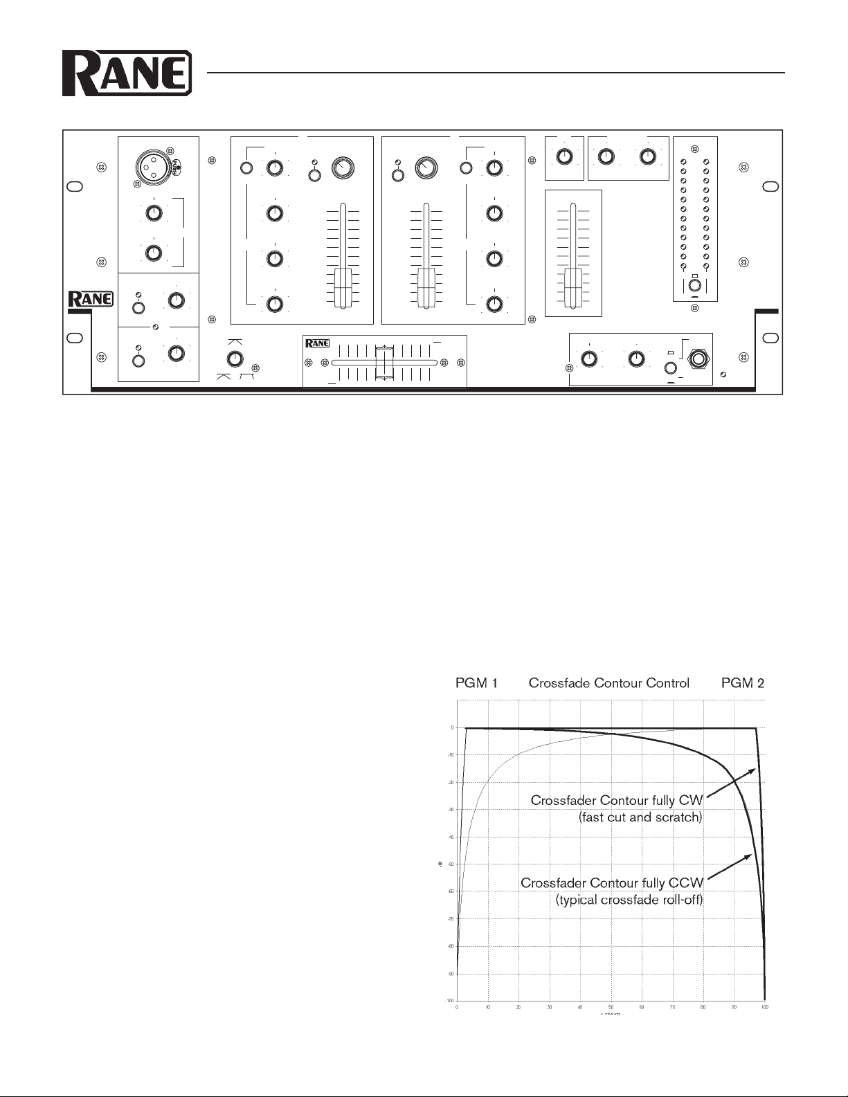
With the CROSSFADER CONTOUR set to full counter-clockwise position, it operates as a typical constant-power crossfader.
Set to clockwise position, the crossfader has the very steep slope as indicated in Figure 1 to the right. Now that was a pretty quick
start, right?
Never connect anything except a Rane RS 1 to the thing
that looks like a red telephone jack on the rear of the
MP 22z. is is an AC supply and requires some special atten-
tion if you do not have an operational power supply exactly like
the one that came with your unit. Consult the Rane factory for a
replacement or substitution.
WEAR PART
is product contains the following wear part subject to the
ninety (90) day warranty period described on page Warranty-1:
(1) Active Crossfader Assembly F 60.
Figure 1. Crossfader Contour control
Manual-1
Page 4

FRONT PANEL DESCRIPTION
CUE LEFT
CUE PGM
PGM RIGHT
MONO
+8
+5
+1
+3
PEAK dBu
-3
-1
-7
-5
-1
0
-1
5
-20
LEFT RIGHT
0
CUE/PGM
6
4
10
8
0
8 2
ZONE
2
6
4
6
10
2
0
ZONE
1
8
10
10
8
0dB
2
4
4
2
0
4
2
4
CU
T
EQ ENGAGE
2
BOOS
T
10
8
4
6
2
4
2
4
4
CU
T
10
0dB
2
4
CUT
6
2
4
BOOS
T
BOOS
T
2
2
LEVEL
STEREO
8
6
4
10
2
0
0
2
PGM
6
2
CU
E
6
LEVELPA
N
0
2
4
2
4
CU
T
0
BOOST
LINE
5LINE 4
PH/LN2
LINE 3 LINE 4
LINE
5
10
8
6
2
4
10
0dB
6
2
4
4
CUT BOOS
T
2
2
4
EQ ENGAGE
4
CUT BOOS
T
2
4
2
CUT BOOS
T
4
4
2
2
6
2
4
8
10
PH/LN1
TM
0
106 8
0
420
04 26810
2
4
2
CUT BOOS
T
4
0
4
2
2
BOOS
T
4
BOOS
T
4
4
CU
T
CU
T
2
2
8
MA
X
2
MI
N
OL
6
MA
X
8
4
MI
N
2
ENGAGE
ENGAGE
4
6
LINE
6
A
C
T
IV
E
C
R
O
S
S
F
A
D
E
R
PWR
MIXER
AUX OUTPUT LEVELS
B
HI-MID
TREBL
E
MID
BASS
EQ
B
MASTER LEVEL
HEADPHONE CONTROL
B
CUE B
INPUT SELECT
A
TREBLE
CUE
A
HI-MID
MID
BASS
EQ
A
CROSSFADER
CONTOUR
A
MAIN MIC
TREBLE
BASS
MIC EQ
REMOTE MIC
MAIN MIC
INPUT SELECT
MP 22z
F
60
1 Front panel MAIN MIC input: Use this XLR connector for connecting a balanced microphone of any impedance.
2 MIC EQ controls: Adjust the frequency contour of both Microphone Inputs. ey have no effect on any other Inputs. Position-
ing these controls to the “12 o'clock” position turns the Mic EQ off.
3 CHANNEL A & B EQ ENGAGE switches: Engaging this switch enables the Channel Equalizer to function. In the out posi-
tion, the Equalizer is bypassed.
4 CHANNEL A & B EQ level controls: ese four rotary controls, when enabled with the EQ ENGAGE switch, are used to
contour the frequency response of the selected Input Channel. is is not designed to be the only Equalizer in the system, this is
intended to provide EQ between varying program materials. We recommend an external graphic equalizer for best overall system
sound, connected between the MASTER OUTPUTS and the amplifier.
5 CUE A or CUE B switches: Engaging any single or combination of CUE pushbuttons sends any program present at the respec-
tive Channel's INPUT SELECT selector to the Headphone and meter cue sections. e yellow LEDs adjacent to each CUE
select button illuminate when the switch is engaged. Not recommended for beat sync lights. See Operating Instructions on page
Manual-6.
6 INPUT SELECT A & B: ese four position rotary switches provide Input selection between the various phono/line inputs for
their respective mixing Channels.
7 AUX LEVEL control: Adjusts the input Level from the AUX LINE IN jacks.
8 ZONE LEVEL controls: Adjust the output Levels of ZONE 1 and ZONE 2.
9 PEAK dBu CUE/PROGRAM meter: Can switch between two display modes. See 0 below.
0 Meter CUE/PROGRAM switch: In the out position, the meter indicates Master Program output level in PEAK dBu in LEFT
q REMOTE MIC ENGAGE switch: When pressed, ENGAGES the REMOTE MIC Input. e adjacent red LED flashes when-
Manual-2
and RIGHT stereo. In the in position, mono CUE level is displayed on the LEFT side and mono Program level is displayed on
the RIGHT side.
ever the switch is pressed in, signalling that the Main Mic is on.
Page 5

w MAIN & REMOTE MIC OVERLOAD indicator: Monitors both Microphone Inputs, before and after the MIC EQ. It lights
whenever these levels exceed 4 dB below clipping. Occasional flickering is normal; however, it should not be allowed to light steadily.
e MAIN MIC ENGAGE switch: When pressed, ENGAGES the MAIN MIC Input. e adjacent red LED flashes whenever the
switch is pressed in, signalling that the Main Mic is on.
r MAIN MIC LEVEL control: Adjusts the Level of the front panel MAIN MIC Input.
t REMOTE MIC LEVEL control: Adjusts the Level of the rear panel REMOTE MIC Input.
y CROSSFADER CONTOUR control: Allows adjusting the “shape” of the CROSSFADER response from a gentle curve for
smooth, long running fades, to the steep pitch required for performance cut and scratch effects. See Figure 1 on page Manual-1.
u A & B Input Channel faders: Control the Levels of the Input selected on each Channel.
i ACTIVE CROSSFADER: Controls the relative level of the Inputs assigned to the A and B Channels. When this fader is at its far
left, only Channel A is heard from the Outputs. As the fader is moved toward the right, the volume of Channel B is increased.
When the fader is centered, both Channels deliver equal volume. As you might expect, at the far right only Channel B is heard
from the Outputs. In the unlikely event of Crossfader trouble, See Replacing the Active Crossfader below. See Figure 1 on page
Manual-1 for response curves of various contour settings.
o MASTER LEVEL fader: Determines the final Level at the MASTER and ZONE OUTPUTS. Unity gain is around “6”.
p HEADPHONE PAN control: Serves two purposes. When the Headphone Mode switch (see s) is in STEREO mode, this con-
trols the relative levels of the Cue and Program mixed together in Stereo. When the Mode is switched to MONO, this controls
the balance between Mono Cue in the left earcup and the Mono Program in the right.
a HEADPHONE LEVEL control: Clockwise rotation of this rotary control increases the Headphone drive Level.
s HEADPHONE mode switch: In the out position, this switch feeds Stereo Cue and Program to both earcups. In the in position
the headphone circuit provides Mono Cue to the Left ear and Mono Program to the Right ear.
d HEADPHONE Output jack: A ¼" tip-ring-sleeve stereo jack delivers signal to stereo headphones.
f POWER “ON” indicator: Illuminates when the MP 22z is connected to an appropriate power source (see Rear Panel r).
FADER CLEANING
With heavy use in harsh environments, the faders may need
lubrication. is treatment extends longevity and can make used
faders as good as new. e fader assembly must be removed from
the MP 22z for proper cleaning. We recommend any of the following cleaning solutions:
Caig Cailube MCL 100% spray lubricant
Caig Cailube MCL 5% spray cleaner
CRC 2-26 (www.crcindustries.com)
REPLACING THE ACTIVE CROSSFADER
e Crossfader may be removed without any disassembly of
the MP 22z itself, and may be performed while the unit is operating with no interruption of the audio signal.
F 60 and F 45 Fader Kits are available from your local retailer
or the factory. e kit includes full assembly including knobs,
ribbon, and face plate.
1. Remove the two (2) outer screws attaching the crossfader as-
sembly to the front panel.
2. Pull the Crossfader Assembly forward and unplug the ribbon
Order CaiLube MCL
CAIG Laboratories, Inc.
12200 atcher Ct.
®
from:
from the connector on the bottom board.
3. Proceed with Cleaning Instructions, or install the replacement
assembly by reversing the above instructions.
Poway, CA 92064
Phone 858-486-8388
Fax 858-486-8398
(www.caig.com)
CLEANING INSTRUCTIONS
1. Hold the fader assembly away from the mixer.
2. Position the fader at mid-travel.
3. Spray cleaner/lubricant into both ends of the fader.
4. Move the fader over its full travel back and forth a few times.
5. Shake excess fluid from the fader assembly.
6. Wipe off excess fluid.
Manual-3
Page 6

REAR PANEL DESCRIPTION
750mA
POWER
MP 22z
RANE CORP.
BALANCED 1/4"
TIP (+) RING (–
)
ACN001.187.837
R
MASTER
L
SLEEVE (GND)
CLASS 2 EQUIPMENT
MADE IN U.S.A.
ZONE 2ZONE 1
R
L
MIC/AUXMIC/AUX
ZONE
1
YES NOYES NO
TAPE OUT
TOTO
R
R
R
L
L
L
LINE
6
TRIM 6
SEND (OUT)
RETURN (IN
)
TAPE
LINE 5
R
L
TRIM 5
LINE 4LINE 3
R
L
TRIM 4
LINE
(RIAA)
PHONO
TRIM 2
TRIM 3
R
PHONO
(RIAA)
PH/LN 1
L
TRIM 1
PH/LN 2
ACTIVE CROSSFADER TECHNOLOGY PATENT PENDING
PHONO
TIP (SIG)
SLEEVE (GND)
RETURN
(IN)
SEND
(OUT)
INPUT
UNBALANCED 1/4"
LINE
GROUND
OUTPUTS
LINE IN
AUX
MASTER LOOP
INPUTS
MIC LOOP
MIC/LINE
REMOTE
1 REMOTE MIC/LINE INPUT: is ¼" tip-sleeve Input is for wireless mics or other high-impedence sources.
2 MICROPHONE LOOP jacks: ese ¼" tip-sleeve connectors are for inserting external signal processing in the microphone
circuit only. ese jacks do not effect the other Inputs.
3 PHONO GROUND screw: is can facilitate your hum chasing, buzz eliminating experiments, providing a place to connect
those extra wires coming out of the turntables. See Chassis Grounding, next page.
4 PHONO/LINE 1 & 2 INPUTS: ese stereo Inputs are switchable from a PHONO (RIAA) stage for magnetic cartridges to a
LINE level Input suitable for any line level device such as a CD player. Each Input may be adjusted with its TRIM control for
level matching purposes if desired.
5 LINE 3, 4, 5 & 6 INPUTS: ese stereo pairs of RCAs connect LINE level Inputs only. Each Input may be adjusted with its
TRIM control for level matching purposes if desired.
6 MASTER LOOP SEND & RETURN: ese stereo pairs of RCA connectors allow inserting external signal processing in the
Master, Zone and Headphone circuits. is feature does not affect the operation of the MIC or AUX INPUTS. ese are switching jacks—always finish the loop when connecting send or return. Only connect to a device that is capable of returning signal
back to the MP 22z.
7 AUX LINE INPUT: is stereo pair of RCA connectors is an extra set of LINE level Inputs with an independent front panel
LEVEL control (see Front Panel, 7).
8 TAPE OUTPUT: ese line level RCA Outputs are intended for use with a tape recorder, but not necessarily restricted to that
purpose. You may be creative. ese Outputs are not affected by the MASTER LEVEL fader.
9 MIC & AUX TO TAPE OUT switch: In the YES position the Mic and Aux signals along with all Inputs are routed to the TAPE
OUTPUT. In the NO position only program material from Inputs 1 through 6 appear at the TAPE OUTPUT.
0 MIC & AUX TO ZONE 1 switch: In the YES position the Mic and Aux signals along with all Inputs are routed to the ZONE 1
OUTPUT. In the NO position only program material from Inputs 1 through 6 appear at the ZONE 1 OUTPUT. Note: Mic and
Aux signals are never routed to the ZONE 2 OUTPUT.
q ZONE OUTPUTS: ese are stereo pairs of line level RCA Outputs with independent front panel OUTPUT LEVEL controls
(see Front Panel, 8) and are not affected by the MASTER LEVEL control.
w MASTER OUTPUTS: ese balanced ¼" TRS (tip-ring-sleeve) Outputs connect to a balanced equalizer or amplifier. ough
not recommended, unbalanced ¼" TS (tip-sleeve) cables may be used for short runs (under 3 meters [10 feet]) to an amplifier
with unbalanced inputs. See RaneNote 110 “Sound System Interconnection” for wiring recommendations.
e Chassis ground point: is screw is provided for connection to chassis ground if required. See Chassis Grounding on the next
page.
r POWER input connector: is is not a telephone jack! Connect an 18 volt AC center-tapped transformer only. Use only a Rane
model RS 1, shipped with the unit, or other RS 1 compatible power supply approved by Rane.
Manual-4
Page 7

MP 22z CONNECTION
When first connecting the MP 22z to other components,
leave the power supply for last. is gives you a chance to make
mistakes and correct them without damaging your fragile speakers, ears and nerves.
All of the line level inputs are unbalanced RCA connectors. Inputs PH/LN1, LINE 3, LINE 4 and LINE 5 appear on
Channel A; while PH/LN2, LINE 4, LINE 5 and LINE 6 each
appear on Channel B. e only restriction is the assignment of
the Phono Inputs, one per Channel A and Channel B. So for you
phono only users, Inputs are pretty simple; Phono 1 is on Channel A and Phono 2 is on Channel B. If you bring a phono signal
into PH/LN 1 or 2 be sure to set the appropriate Line/Phono
switch to PHONO. Like a mic input, a phono requires a lot of
gain plus RIAA equalization.
e Aux Line Input has its own Level control on the front
panel and sums with the other signals before the Master and
Zone Level controls.
e Main Mic Input on the front panel allows use of a gooseneck mounted microphone. e connector is rotated such that
a right angle connector may be used when connecting via mic
cable. e Remote Mic Input is located on the rear panel and has
enough range on it's Level control to accommodate mic or line
level inputs. e Mic Loop has an unbalanced ¼" TS (Tip/
Sleeve) Output (send) and a separate ¼" TS (Tip/Sleeve) Input
(return). e effect in this Loop affects both Mics simultaneously.
Inserting plugs into the Master Loop Return breaks the
signal path thru the unit unless they contain the return from an
outside device that got its signal from the Master Loop Send. In
other words, these are switching jacks—only use a stereo effects
device that passes signal completely patched through.
e Mic and Aux can be switched to appear or not appear
on the Zone 1 Output, and the Mic and Aux can be switched
to appear or not appear on the Tape Output, determined by the
YES/NO switches on the rear panel.
If you are connecting balanced devices (3-conductor) to
either the Input or Output of the MP 22z, consult the included
RaneNote “Sound System Interconnection” for proper wiring
procedures.
IMPORTANT NOTE
CHASSIS GROUNDING
If your system exhibits excessive hum or buzzing, there is an
incompatibility in the grounding configuration between units
somewhere. Your mission, should you accept it, is to discover
how your particular system wants to be grounded. Here are some
things to try:
1. Try combinations of lifting grounds on units that are sup-
plied with ground lift switches or links.
2. If your equipment is in a rack, verify that all chassis are
tied to a good earth ground, either through the line cord grounding pin or the rack screws to another grounded chassis like the
amplifier.
3. Units with outboard power supplies do not ground the
chassis through the line cord. Make sure that these units are
grounded either to another chassis which is earth grounded, or
directly to a known ground by means of a wire connected to
a screw on the chassis with a star washer to guarantee proper
contact.
Please refer to the RaneNote “Sound System Interconnection”
included with this manual for further information on system
grounding.
Manual-5
Page 8

OPERATING INSTRUCTIONS
INITIAL OPERATION
For starters, connect a CD player to LINE 1 Input and set
the PHONO/LINE switch to LINE. If a turntable is used, set
this switch to PHONO. Make sure all faders are set to zero, the
MIC and EQ are disengaged (switches out) and all rotary controls are either fully CCW (LEVEL controls) or in their center
detents (EQs), whichever applies. Leave the rear panel INPUT
TRIMS at full CW (factory preset). Switch the Channel A INPUT SELECT to PH/LN 1. Simultaneously raise the Channel
A fader and the MASTER LEVEL fader. Before you cover much
travel on the faders you should begin to hear the results. If you
do not, shut everything down and recheck your connections,
power to the mixer (look for the yellow POWER light) and ancillary devices (EQs, crossovers, power amplifiers, etc.) Once you
have established an output from whatever is connected to LINE
1, go ahead and try the other Inputs.
INPUT FADERS
e Input Channel faders should be set near their maximum
levels to preclude requiring excessive gain from the Output stage.
Achieve optimum noise performance by running the majority of
the gain on the Input stages. Taking the least amount of gain on
the Output stage ensures that the system doesn’t have to amplify
the unavoidable noise generated by the input buffers and sum
ming amplifiers.
INPUT TRIMS
e TRIMS allow various devices to drive each Input equal
ly. If you have two CD players, you might want to play the same
CD on each player. Now lower the TRIM on the louder player
(the other one should be up all the way) so the MP 22z meter
peaks match for both players. You can use a similar method with
the same recording on different formats to match a turntable
to a CD, or a cassette to a CD or video deck. If your source has
an Output VU of its own, push the Input Channel fader all the
way up, set the MASTER LEVEL control to “6” (unity gain),
and adjust the TRIM so that both meters reach 0 dB at the same
time.
HEADPHONE CONTROL (CUE) SYSTEM
First, you must have signal present at one of the Inputs.
(Well, at least you do to make sure it works.) Depressing the
CUE switch for the respective Input Channel presents this
signal to the headphone amplifier. An LED illuminates next
to the Input CUE switch, attesting to the fact that it is pushed
down. ere are two choices of listening to the CUE. With the
STEREO/MONO switch down, you get Mono Cue in the Left
ear and Mono Program in the Right, and PAN controls the
amount of each. With this switch up, you get Stereo Program in
both ears or Stereo Cue in both ears, depending on the rotation
of the PAN control. e overall volume is then controlled by the
HEADPHONE LEVEL control.
-
-
When a CUE is active at either Input Channel, and if the
Meter CUE/PROGAM switch is down, the monoed Cue signal
is routed to the LEFT side of the PEAK dBu Meter, while
monoed Program is displayed on the RIGHT. is is useful to
match a source before it is faded in to the level of the program
currently playing, or for visual beat matching.
USING THE CROSSFADER
e volume of the two Input Channels begins from the fad
ers on Channels A and B. eir outputs are under the control of
the Crossfader. When in its left-most position, only Channel A
appears at the Outputs. In the center, both Channels are present
in equal levels, and only Channel B will be heard once the far
right is reached. With the CROSSFADER CONTOUR set to
the full ccw position, the sound pressure level does not change
as this transition progresses. See Figure 1 on page Manual-1 for
response curves.
MICROPHONE OPERATION.
Connect the mic to the appropriate connector. Leave the
MASTER LEVEL fader in roughly the same location as it was
for the music that’s been playing, press the MIC ENGAGE
switch (notice the flashing LED) and adjust the MAIN MIC (or
REMOTE MIC) LEVEL. e tonal balance may be adjusted
via the MIC EQ controls. Modifying the sound of the mic in
this way won’t affect the EQ of the music in the system. e
three Equalizer sections (Mic and Input A and B Channels) are
totally independent. When the mic is not in use, release the MIC
ENGAGE switch again to its up position, extinguishing the
LED. Should the microphone preamp become overloaded, the
red LED Overload light illuminates. If this is a problem, lower
the appropriate MIC LEVEL control and increase the level of the
MASTER LEVEL fader to restore desired microphone level.
ZONE OUTPUTS
e ZONE OUTPUTS are additional stereo Outputs with
their own ZONE LEVEL controls that can be routed to am
plifers that feed the bar, another tape recorder, etc. If you would
like the MIC and AUX signals to be removed from the ZONE 1
OUTPUT place the rear panel switch in the NO position. In the
YES position, you will get MIC and AUX signals in ZONE 1.
-
-
©Rane Cor poration 10802 47th Ave. W., Mukilteo WA 98275-5098 TEL 425-35 5-6000 FAX 425-347-7757 WEB www.rane.com
Manual-6
103293
 Loading...